EP1972903A2 - Thermal flowmeter - Google Patents
Thermal flowmeter Download PDFInfo
- Publication number
- EP1972903A2 EP1972903A2 EP08001211A EP08001211A EP1972903A2 EP 1972903 A2 EP1972903 A2 EP 1972903A2 EP 08001211 A EP08001211 A EP 08001211A EP 08001211 A EP08001211 A EP 08001211A EP 1972903 A2 EP1972903 A2 EP 1972903A2
- Authority
- EP
- European Patent Office
- Prior art keywords
- heat resistor
- temperature
- resistor
- length
- heat
- Prior art date
- Legal status (The legal status is an assumption and is not a legal conclusion. Google has not performed a legal analysis and makes no representation as to the accuracy of the status listed.)
- Granted
Links
- 238000010438 heat treatment Methods 0.000 claims description 26
- 239000012530 fluid Substances 0.000 claims description 15
- 239000000758 substrate Substances 0.000 claims description 10
- 238000002485 combustion reaction Methods 0.000 claims description 9
- 239000010409 thin film Substances 0.000 claims description 9
- 239000000446 fuel Substances 0.000 claims description 8
- 238000002347 injection Methods 0.000 claims description 7
- 239000007924 injection Substances 0.000 claims description 7
- 238000011144 upstream manufacturing Methods 0.000 claims description 6
- 229910021421 monocrystalline silicon Inorganic materials 0.000 claims description 4
- 229910021420 polycrystalline silicon Inorganic materials 0.000 claims description 4
- 239000007769 metal material Substances 0.000 claims description 3
- 230000001105 regulatory effect Effects 0.000 claims 1
- 230000035945 sensitivity Effects 0.000 abstract description 11
- 238000001514 detection method Methods 0.000 abstract description 7
- BASFCYQUMIYNBI-UHFFFAOYSA-N platinum Chemical compound [Pt] BASFCYQUMIYNBI-UHFFFAOYSA-N 0.000 description 6
- 230000006866 deterioration Effects 0.000 description 5
- 238000000034 method Methods 0.000 description 4
- 239000010408 film Substances 0.000 description 3
- 239000000463 material Substances 0.000 description 3
- 229910052697 platinum Inorganic materials 0.000 description 3
- 229910000990 Ni alloy Inorganic materials 0.000 description 2
- XUIMIQQOPSSXEZ-UHFFFAOYSA-N Silicon Chemical compound [Si] XUIMIQQOPSSXEZ-UHFFFAOYSA-N 0.000 description 2
- QVGXLLKOCUKJST-UHFFFAOYSA-N atomic oxygen Chemical compound [O] QVGXLLKOCUKJST-UHFFFAOYSA-N 0.000 description 2
- 238000010586 diagram Methods 0.000 description 2
- 230000000694 effects Effects 0.000 description 2
- 238000002474 experimental method Methods 0.000 description 2
- 238000004519 manufacturing process Methods 0.000 description 2
- 238000005259 measurement Methods 0.000 description 2
- 239000001301 oxygen Substances 0.000 description 2
- 229910052760 oxygen Inorganic materials 0.000 description 2
- 239000004065 semiconductor Substances 0.000 description 2
- 229910052710 silicon Inorganic materials 0.000 description 2
- 239000010703 silicon Substances 0.000 description 2
- 230000015556 catabolic process Effects 0.000 description 1
- 239000000919 ceramic Substances 0.000 description 1
- 238000011109 contamination Methods 0.000 description 1
- 230000003247 decreasing effect Effects 0.000 description 1
- 239000000428 dust Substances 0.000 description 1
- 238000005516 engineering process Methods 0.000 description 1
- 230000007613 environmental effect Effects 0.000 description 1
- 238000005530 etching Methods 0.000 description 1
- 239000007789 gas Substances 0.000 description 1
- 238000009413 insulation Methods 0.000 description 1
- 230000007774 longterm Effects 0.000 description 1
- 238000005459 micromachining Methods 0.000 description 1
- 239000003921 oil Substances 0.000 description 1
- 230000005855 radiation Effects 0.000 description 1
- XLYOFNOQVPJJNP-UHFFFAOYSA-N water Substances O XLYOFNOQVPJJNP-UHFFFAOYSA-N 0.000 description 1
Images



Classifications
-
- G—PHYSICS
- G01—MEASURING; TESTING
- G01F—MEASURING VOLUME, VOLUME FLOW, MASS FLOW OR LIQUID LEVEL; METERING BY VOLUME
- G01F1/00—Measuring the volume flow or mass flow of fluid or fluent solid material wherein the fluid passes through a meter in a continuous flow
- G01F1/68—Measuring the volume flow or mass flow of fluid or fluent solid material wherein the fluid passes through a meter in a continuous flow by using thermal effects
- G01F1/684—Structural arrangements; Mounting of elements, e.g. in relation to fluid flow
- G01F1/688—Structural arrangements; Mounting of elements, e.g. in relation to fluid flow using a particular type of heating, cooling or sensing element
- G01F1/69—Structural arrangements; Mounting of elements, e.g. in relation to fluid flow using a particular type of heating, cooling or sensing element of resistive type
- G01F1/692—Thin-film arrangements
-
- F—MECHANICAL ENGINEERING; LIGHTING; HEATING; WEAPONS; BLASTING
- F02—COMBUSTION ENGINES; HOT-GAS OR COMBUSTION-PRODUCT ENGINE PLANTS
- F02D—CONTROLLING COMBUSTION ENGINES
- F02D41/00—Electrical control of supply of combustible mixture or its constituents
- F02D41/02—Circuit arrangements for generating control signals
- F02D41/18—Circuit arrangements for generating control signals by measuring intake air flow
- F02D41/187—Circuit arrangements for generating control signals by measuring intake air flow using a hot wire flow sensor
-
- G—PHYSICS
- G01—MEASURING; TESTING
- G01F—MEASURING VOLUME, VOLUME FLOW, MASS FLOW OR LIQUID LEVEL; METERING BY VOLUME
- G01F1/00—Measuring the volume flow or mass flow of fluid or fluent solid material wherein the fluid passes through a meter in a continuous flow
- G01F1/68—Measuring the volume flow or mass flow of fluid or fluent solid material wherein the fluid passes through a meter in a continuous flow by using thermal effects
- G01F1/696—Circuits therefor, e.g. constant-current flow meters
Definitions
- the present invention relates to a thermal flowmeter for measuring a fluid flow rate, the thermal flowmeter including a heat resistor formed on a substrate.
- the mainstream of a flow rate sensor for detecting an intake air amount of an internal combustion engine of an automobile or the like is, for example, a thermal air mass flow sensor capable of directly measuring a mass flow rate.
- a thermal flowmeter which has a sensor element fabricated on a semiconductor substrate of silicon (Si) or the like by use of micromachining technology.
- a heat resistor is formed on a thin film portion of several microns formed on the semiconductor substrate.
- the semiconductor-type thermal flowmeter Since the heat resistor is formed on a thin film, the semiconductor-type thermal flowmeter has a small heat capacity, and hence is capable of rapid response and low-power drive. Moreover, microfabrication makes it easier to form a configuration capable of detecting a temperature variation between the upstream and downstream of the heat resistor, and of thereby judging whether the flow is a forward flow or a reverse flow.
- thermal flowmeter of the above type examples include Japanese Patent Application Laid-open Publication Nos. 2004-205498 and 2005-283381 .
- Japanese Patent Application Laid-open Publication No. 2004-205498 discloses a technique which improves sensitivity while reducing power consumption by using boron-doped single crystal silicon to form upstream and downstream heaters, and also by setting the line widths of the heaters at 7 micrometers or greater.
- Japanese Patent Application Laid-open Publication No. 2005-283381 discloses a technique for enabling a power supply from an ECU (engine control unit) as a power source for the thermal flowmeter, by reducing the amount of heat produced by a temperature sensing resistor in order that a sensor output error due to variations in the voltage outputted from the ECU can be reduced.
- a pressure sensor and a temperature sensor used in an automobile are operable with power supply from an ECU.
- the thermal flowmeter can receive power supply from an ECU rather than from a battery, the thermal flowmeter does not need circuitry for protection against electrical noise and overvoltage as well as a power supply line from a battery.
- a power supply voltage is limited to 5 V; the current, 10 mA to 20 mA supply; and the electric power, 50 mW to 100 mW.
- a power supply voltage is limited to 5 V; the current, 10 mA to 20 mA supply; and the electric power, 50 mW to 100 mW.
- a flow rate is measured on the basis of the amount of heat radiated from the heat resistor under the influence of airflow or a temperature distribution in the vicinity of the heat resistor, while a heating temperature for the heat resistor is kept constant.
- power consumption by a heat resistor formed on the sensor element is particularly high in a thermal flowmeter.
- greater airflow leads to higher power consumption by a heat resistor. This is due to the facts that a flow velocity of an intake air taken in by the internal combustion engine of an automobile sometimes reaches 80 m/s at maximum, and that power needs to be continuously supplied to the heat resistor in order to keep the temperature of the heat resistor constant even against such a high flow velocity.
- An object of the present invention is to provide a thermal flowmeter capable of receiving power supply from a control unit, and capable of achieving low power consumption without reducing the heating temperature for its heat resistor.
- a thermal flowmeter of the present invention includes a heat resistor and a temperature sensor element.
- the heat resistor is supplied with power so that the temperature of the heat resistor is higher than a fluid temperature by a temperature increase ⁇ Th (°C), and a fluid flow rate is measured by using a value outputted from the temperature sensor element.
- the relationship between a length Lh and the temperature increase ⁇ Th is set so as to satisfy a formula: 1.4 ⁇ ⁇ Th ⁇ Lh / Ph ⁇ 2.8, where Ph denotes maximum permissible power (W) to be supplied to the heat resistor, and Lh denotes the length (m) of the heat resistor in a direction perpendicular to the direction of flow of the fluid.
- the present invention can provide a thermal flowmeter capable of receiving power supply from a control unit without requiring an expensive protection circuit, and capable of achieving low power consumption without reducing the heating temperature for the heat resistor.
- the first embodiment as will be described below is an example of the present invention as applied to an air mass flow sensor for measuring an intake air amount of an internal combustion engine.
- Fig. 1 is a plan view showing a sensor element 1 of the thermal flowmeter according to the first embodiment of the present invention.
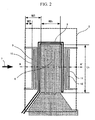
- Fig. 2 is an enlarged view of a diaphragm unit (or thin film portion) 2 shown in Fig. 1
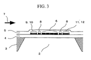
- Fig. 3 is a cross-sectional view taken along the line A-A' of Fig. 2 .
- a substrate 3 of the sensor element 1 is made of a material having good thermal conductivity, such as silicon or ceramics. Then, an insulating film 4 is formed on top of the substrate 3, which in turn is subjected to etching on the back side thereof to thereby form the diaphragm unit 2 on the insulating film 4.
- a heat resistor 6 is formed on the surface of the diaphragm unit 2.
- the heat resistor 6 is heated so that its temperature is higher than the temperature of airflow 7 by a certain temperature.
- a heating temperature sensor 8 is formed around the heat resistor 6, and temperature variation sensors 9, 10, 11 and 12 are formed on both sides of the heating temperature sensor 8 (or on the upstream and downstream sides of the airflow 7).
- Temperature sensing resistors 13, 14 and 15 each having a resistance value changing according to the temperature of the airflow 7 are formed in the vicinity of the diaphragm unit 2 on the substrate 3.
- the temperature sensing resistors 13 to 15 and the heating temperature sensor 8 are combined to form a bridge circuit.
- the bridge circuit detects a change in temperature of the heating temperature sensor 8, controls a heating current for the heat resistor 6 on the basis of the detected result, and controls a heating temperature of the heat resistor 6.
- the heat resistor 6 is heated so that the temperature thereof can be higher than that of the airflow 7 by the certain temperature. Then, a temperature variation occurs in the upstream and downstream vicinities of the heat resistor 6 by the airflow 7 being produced. As a result, the heat resistor 6 undergoes a drop in temperature on the upstream side and a rise in temperature on the downstream side.
- the temperature variation sensors 9, 10, 11 and 12 detect this change in temperature to thereby obtain a signal according to an air flow rate.
- the heat resistor 6, the heating temperature sensor 8, the temperature variation sensors 9, 10, 11 and 12 and the temperature sensing resistors 13, 14 and 15 are made of a material having a resistance value changing according to the temperature and having a relatively high temperature coefficient of resistance.
- impurity-doped polycrystalline silicon is used as an example.
- impurity-doped single crystal silicon may be used to form the heat resistor 6, the heating temperature sensor 8, the temperature variation sensors 9, 10, 11 and 12 and the temperature sensing resistors 13, 14 and 15.
- the heat resistor 6, the heating temperature sensor 8, the temperature variation sensors 9 to 12 and the temperature sensing resistor 13 to 15, which are present on the sensor element 1, are connected to pads 16a to 16n, and wired through the pads 16a to 16n to a driving circuit or the like by means of bonding wires.
- the heat resistor 6, the heating temperature sensor 8, the temperature variation sensors 9 to 12 and the temperature sensing resistor 13 to 15 are easy to connect prior to leading to pad units, because of being made of the same material.
- the heating temperature sensor 8 and the temperature sensing resistors 13, 14 and 15, in particular, have connections in the sensor element to form the bridge circuit, and thereby, the number of pads is reduced, and hence, the size of the sensor element is advantageously reduced.
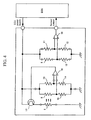
- Fig. 4 is a diagram showing the driving and detecting circuitry of the sensor element 1 according to the first embodiment.
- the first embodiment of the present invention is configured to provide the supply of power from an ECU as shown in Fig. 4 in order that an automotive ECU powers the thermal flowmeter to drive it.
- a general ECU has a power supply voltage of about 5 V and a current of the order of 20 mA.
- the bridge circuit is formed by the heating temperature sensor 8 and the temperature sensing resistors 13, 14 and 15. Specifically, the heating temperature sensor 8 and the temperature sensing resistor 15 are connected in series, and the temperature sensing resistors 13 and 14 are connected in series. Then, the heating temperature sensor 8 and the temperature sensing resistor 15 are connected in parallel with the temperature sensing resistors 13 and 14. Then, a non-inverting input terminal of a differential amplifier 18 is connected to the junction of the heating temperature sensor 8 and the temperature sensing resistor 15, and an inverting input terminal of the differential amplifier 18 is connected to the junction of the temperature sensing resistors 13 and 14.
- the bridge circuit is powered by an ECU power supply to operate on a certain voltage.
- a differential voltage of the bridge circuit or equivalently an output voltage from the differential amplifier 18 is fed to a base of a transistor 17.
- a collector of the transistor 17 is connected to the ECU power supply, and an emitter thereof is grounded through the heat resistor 6.
- the transistor 17 is configured to feed a current to the heat resistor 6, and to heat the heat resistor 6, under control of an output from the differential amplifier 18.
- the bridge circuit is formed by the temperature variation sensors 9, 10, 11 and 12. Specifically, the temperature variation sensors 9 and 12 are connected in series, and the temperature variation sensors 11 and 10 are connected in series. Then, the temperature variation sensors 9 and 12 are connected in parallel with the temperature variation sensors 11 and 10. Then, a non-inverting input terminal of a differential amplifier 19 is connected to the junction of the temperature variation sensors 9 and 12, and an inverting input terminal of the differential amplifier 19 is connected to the junction of the temperature variation sensors 11 and 10.
- the amplifier 19 detects a differential voltage of the bridge circuit formed of the temperature variation sensors 9, 10, 11 and 12 to thereby obtain a sensor output in accordance with the air flow rate.
- This bridge circuit is also configured to be powered by the ECU power supply to operate on its voltage.
- the thermal flowmeter is limited in power consumption, and thus it is required that the voltage be within 5 V and the current fall within the order of 20 mA. Further, a current of the order of 10 mA is required in order that electrical circuitry, such as an amplifier, operates. Hence, the maximum permissible current to be supplied to the sensor element 1 is limited to the order of 10 mA.
- the heat resistor 6 in particular, requires power.
- Other components namely, the heating temperature sensor 8, the temperature variation sensors 9, 10, 11 and 12 and the temperature sensing resistors 13, 14 and 15, can be given high resistance to reduce power consumption. It is therefore important that the heat resistor 6 be configured to be powered by 5 V and 10 mA, or equivalently at 50 mW or less.
- Power consumption by the heat resistor 6 is determined by heat radiation to the airflow 7 and heat conduction to the substrate 3.
- the full effect of thermal insulation can be obtained by the presence of the diaphragm unit 2, provided that a distance W1 from an edge of the heat resistor 6 to an edge of the diaphragm unit 2 is 100 micrometers or greater, and a film thickness of the diaphragm unit 2 is 5 micrometers or less.
- a distance W2 from an edge of the temperature variation sensors 9 and 10 to the edge of the diaphragm unit 2 be 50 micrometers or greater, since the heat conduction to the substrate 3 can possibly cause a drop in temperature of the temperature variation sensors 9, 10, 11 and 12 and hence a deterioration in detection sensitivity.
- the amount of heat radiated from the heat resistor 6 reaches a maximum when the airflow 7 reaches a maximum. Allowance must therefore be made for power consumption at a high flow rate.
- the dimension in a substantially parallel direction of the flow of a fluid is defined as a width Wh (m) of the heat resistor 6, and the dimension in a direction perpendicular to the direction of the flow of the fluid is defined as a length Lh (m) of the heat resistor 6.
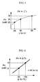
- Fig. 5 is a graph showing the relationship between a flow velocity v of air (indicated by the horizontal axis (in m/s)) and power consumption Ph by the heat resistor 6 (indicated by the vertical axis (in mW)).
- Fig. 6 is a graph showing the relationship between a temperature increase ⁇ Th in the heat resistor 6 (indicated by the horizontal axis (in °C)) and the power consumption Ph by the heat resistor 6 (indicated by the vertical axis (in mW)).
- Fig. 7 is a graph showing the relationship between the length Lh of the heat resistor 6 (indicated by the horizontal axis (in micrometers)) and the power consumption Ph by the heat resistor 6 (indicated by the vertical axis (in mW)).
- Fig. 8 is a graph showing the relationship between the width Wh of the heat resistor 6 (indicated by the horizontal axis (in micrometers)) and the power consumption Ph by the heat resistor 6 (indicated by the vertical axis (in mW)).
- flow velocities v are 20, 40 and 80 m/s respectively in correspondence with 23, 29 and 38 milliwatts of power consumption by the heat resistor 6, and the power consumption Ph is substantially proportional to the one-half power of the flow velocity v.
- temperature increases ⁇ Th are 50°C and 100°C respectively in correspondence with 6 and 12 milliwatts of power consumption by the heat resistor 6, and the power consumption Ph is proportional to the temperature increase ⁇ Th.
- lengths Lh are 600 and 700 micrometers respectively in correspondence with 30 and 40 milliwatts of power consumption by the heat resistor 6, and the power consumption Ph is substantially proportional to the length Lh of the heat resistor 6.
- widths Wh are 100, 260 and 450 micrometers respectively in correspondence with 20, 33 and 44 milliwatts of power consumption by the heat resistor 6, and the power consumption Ph is proportional to the length Lh of the heat resistor 6, and is proportional to the one-half power of the width Wh of the heat resistor 6.
- a reduction in the width Wh of the heat resistor 6 causes a significant drop in temperature of the temperature variation sensors 11 and 12 on the downstream side particularly at a high flow rate, and hence a deterioration in sensitivity.
- setting the width Wh at a large value causes an increase in the overall width of the diaphragm unit 2, and hence a decrease in breakdown strength of the diaphragm unit 2. It is therefore desirable that the width Wh lies between 100 micrometers and 400 micrometers (100 ⁇ Wh ⁇ 400).
- the optimum relationship between the length Lh of the heat resistor 6 and the temperature increase ⁇ Th for the heat resistor 6 be set to satisfy Formula (3), provided that the width Wh of the heat resistor 6 lies between 100 micrometers and 400 micrometers (100 ⁇ Wh ⁇ 400): 1.4 ⁇ ⁇ ⁇ Th ⁇ Lh / Ph max ⁇ 2.8 where Phmax denotes the maximum permissible power consumption (in watts) which is to supply to the heat resistor 6. It is preferable that, for example for 50 mW of power consumption Phmax, the optimum relationship between the length Lh of the heat resistor 6 and the temperature increase ⁇ Th in the heat resistor 6 be set to satisfy Formula (4). 0.07 ⁇ ⁇ ⁇ Th ⁇ Lh ⁇ 0.14
- the maximum permissible voltage and current for the supply of power from the ECU to the heat resistor 6 is 5 ⁇ 0.5 V and 10 mA, respectively. Since the power supply voltage can possibly vary ⁇ 0.5 V, the maximum permissible power for supply to the heat resistor 6 must be set to 45 mW.
- the heat resistor 6 according to the first embodiment of the present invention is made of the impurity-doped polycrystalline silicon, and thus has a temperature coefficient of resistance of the order of 1000 ppm/°C.
- a change in the ambient temperature from 25°C to 125°C causes a 1.1-fold increase in the resistance value Rh of the heat resistor 6.
- the 1.1-fold increase in the resistance value causes a 1.1 - fold increase in an applied voltage, which, in turn, can possibly exceed the maximum permissible applied voltage.
- the center value of the power consumption by the heat resistor 6 be set to 40 mW (i.e., 45 (mW) ⁇ 0.9 ⁇ 40 (mW)), allowing for a change in voltage caused by a change in resistance of the heat resistor 6.
- Wiring resistance is also applied to the heat resistor 6.
- a wiring unit 20 is formed between the heat resistor 6 and the pads 16i and 16j, as shown in Fig. 1 .
- the presence of resistance of the wiring unit 20 causes a loss of power consumption.
- the resistance value of the wiring unit 20 is set at about 10% of the resistance value of the heat resistor 6.
- the power consumption by the heat resistor 6 is 90% of 40 mW, that is, approximately 36 mW, allowing for a loss of power at the wiring unit 20.
- Ph max 36 ( mW )
- the temperature increase ⁇ Th is defined as an average temperature of the heat resistor 6, since the heat resistor 6 has a temperature profile in a planar direction. Measurement of the temperature increase ⁇ Th does not contain the temperature of the wiring unit 20 of the heat resistor 6. In the case where the temperature increase ⁇ Th changes according to the flow rate of the airflow 7, the temperature increase ⁇ Th is set when the airflow 7 has the maximum flow velocity.
- the sensitivity of the thermal flowmeter is determined in accordance with the temperature increase ⁇ Th, and the higher ⁇ Th value is, the better the sensitivity becomes.
- an increase in the ⁇ Th value causes an increase in deterioration in resistance of the heat resistor 6 and the temperature increase sensor 8, and hence a deterioration in long-term reliability. It is therefore preferable that the temperature increase ⁇ Th be set at 200°C or lower.
- the low ⁇ Th value increases the likelihood of adhesion of dust, oil and the like in the air, and further leads to a great influence of adhesion of water. It is therefore preferable that the temperature increase ⁇ Th be set at 80°C or higher.
- Formula (3) is expressed as Formula (6) below.
- Formula (4) is expressed as Formula (7). 0.07 ⁇ ⁇ ⁇ Th ⁇ Lh ⁇ v / 80 ⁇ 0.14
- the resistance value Rh of the heat resistor 6 is set at its optimum value in the following manner.
- the resistance value Rh is set to lie between 360 ⁇ and 540 ⁇ , assuming that resistance variations depending on a manufacturing process are within ⁇ 10%, and that resistance variations due to the change in the ambient temperature are within ⁇ 10%.
- the power consumption by the heat resistor 6 can be reduced under certain conditions, and the certain conditions have been set.
- the conditions for maintaining the good flow rate detection sensitivity are that the relationship among the length Lh of the heat resistor 6, the temperature increase ⁇ Th in the heat resistor 6, and the maximum permissible power Phmax for supply to the heat resistor 6 satisfies Formula (3), provided that the width Wh of the heat resistor 6 lies between 100 micrometers and 400 micrometers (100 ⁇ Wh ⁇ 400).
- the length Lh of the heat resistor 6 and the temperature increase ⁇ Th in the heat resistor 6 are set so that the power consumption Phmax is reduced within a range in which Formula (3) is satisfied, thereby making it possible to reduce the power consumption by the thermal flowmeter while maintaining the good flow rate detection sensitivity.
- the second embodiment of the present invention is characterized in that the heat resistor 6, the heating temperature sensor 8, the temperature variation sensors 9, 10, 11 and 12 and their wiring units according to the first embodiment are made of a metallic material, such as a platinum thin film or a nickel alloy thin film.
- the platinum thin film has a temperature coefficient of resistance of 2000 ppm/°C to 4000 ppm/°C. Thus, there is a great change in resistance due to the change in the ambient temperature, as compared to the first embodiment.
- the temperature coefficient of resistance is set at 3000 ppm/°C
- This exhibits wide resistance variations, and hence causes wide variations in applied voltage, as compared to the heat resistor according to the first embodiment.
- the center value of the maximum permissible power is approximately 31 mW, assuming that the loss of power through the wiring unit 20 of the heat resistor 6 is 10%.
- the resistance variations due to the ambient temperature are approximately within ⁇ 30%, since variations in the resistance value depending on the manufacturing process are within ⁇ 10%, and the temperature coefficient of resistance is higher. It is therefore preferable that the resistance value Rh of the heat resistor 6 be set to lie between 270 ⁇ and 630 ⁇ , with the center at 450 ⁇ .
- the second embodiment of the present invention can reduce a deterioration in resistance with time due to heating as compared to the first embodiment in which the polycrystalline silicon or the single crystal silicon is used, when the heat resistor 6, the heating temperature sensor 8, the temperature variation sensors 9, 10, 11 and 12 and their wiring units are made of the metallic material, such as the platinum thin film or the nickel alloy thin film.
- the temperature increase ⁇ Th in the heat resistor 6 be set to lie between 80°C and 300°C.
- Fig. 9 is an illustration showing a third embodiment of the present invention, showing an operation control system for an internal combustion engine of an electronic fuel injection type including the thermal flowmeter of the present invention as applied to an air flow rate measuring apparatus 101.
- intake air 29 taken in through an air cleaner 100 is taken in by an engine cylinder 107 through a body 102 having the air flow rate measuring apparatus 101 disposed therein, an air intake duct 103, a throttle body 104, and an intake manifold 106 including an injector (or a fuel injection valve) 105 supplied with fuel. Then, gas 108 generated by the engine cylinder 107 is exhausted through an exhaust manifold 109 to the outside.
- An air flow rate signal and an intake air temperature signal outputted by the air flow rate measuring apparatus 101, a throttle valve angle signal outputted by a throttle angle sensor 111, an oxygen content signal outputted by an oxygen analyzer 112 disposed in the exhaust manifold 109, and an engine speed signal outputted by an engine speed tachometer 113 are fed to an ECU 114.
- the ECU 114 sequentially performs operation on the fed signals to determine an optimum fuel injection quantity and an idle air control valve travel, and controls the injector 105 and an idle air control valve 115 by using the determined values.
- the air flow rate measuring apparatus 101 as applied to the internal combustion engine of the electronic fuel injection type enables the supply of power from the ECU 114, and thus enables low power consumption without reducing the heating temperature of the heat resistor, that is, without reducing flow-rate detection accuracy (or engine control accuracy).
- the present invention may be applied not only to the thermal flowmeter for measuring air flow rate fed to the internal combustion engine of the automobile, but also to flow rate measurement for use in control using a diesel engine of a ship, a power generator, or the like.
Landscapes
- Physics & Mathematics (AREA)
- Fluid Mechanics (AREA)
- General Physics & Mathematics (AREA)
- Measuring Volume Flow (AREA)
Abstract
Description
- The present invention relates to a thermal flowmeter for measuring a fluid flow rate, the thermal flowmeter including a heat resistor formed on a substrate.
- The mainstream of a flow rate sensor for detecting an intake air amount of an internal combustion engine of an automobile or the like is, for example, a thermal air mass flow sensor capable of directly measuring a mass flow rate.
- Recently, a thermal flowmeter has been proposed which has a sensor element fabricated on a semiconductor substrate of silicon (Si) or the like by use of micromachining technology. In such a semiconductor-type thermal flowmeter, a heat resistor is formed on a thin film portion of several microns formed on the semiconductor substrate.
- Since the heat resistor is formed on a thin film, the semiconductor-type thermal flowmeter has a small heat capacity, and hence is capable of rapid response and low-power drive. Moreover, microfabrication makes it easier to form a configuration capable of detecting a temperature variation between the upstream and downstream of the heat resistor, and of thereby judging whether the flow is a forward flow or a reverse flow.
- Examples of the thermal flowmeter of the above type are disclosed in .Japanese Patent Application Laid-open Publication Nos.
2004-205498 2005-283381 - Japanese Patent Application Laid-open Publication No.
2004-205498 - Japanese Patent Application Laid-open Publication No.
2005-283381 - A pressure sensor and a temperature sensor used in an automobile are operable with power supply from an ECU. Thus, if the thermal flowmeter can receive power supply from an ECU rather than from a battery, the thermal flowmeter does not need circuitry for protection against electrical noise and overvoltage as well as a power supply line from a battery.
- The techniques disclosed in Japanese Patent Application Laid-open Publication Nos.
2004-205498 2005-283381 - However, in the case of employing power supply from an ECU, voltage, current and electric power are significantly limited as compared to the case of using battery power. For example, a power supply voltage is limited to 5 V; the current, 10 mA to 20 mA supply; and the electric power, 50 mW to 100 mW. Hence, it is necessary to reduce power consumption by and an operating voltage for the heat resistor in order to drive a thermal flowmeter by using power supply from an ECU.
- In many thermal flowmeters, a flow rate is measured on the basis of the amount of heat radiated from the heat resistor under the influence of airflow or a temperature distribution in the vicinity of the heat resistor, while a heating temperature for the heat resistor is kept constant. Thus, power consumption by a heat resistor formed on the sensor element is particularly high in a thermal flowmeter. Further, greater airflow leads to higher power consumption by a heat resistor. This is due to the facts that a flow velocity of an intake air taken in by the internal combustion engine of an automobile sometimes reaches 80 m/s at maximum, and that power needs to be continuously supplied to the heat resistor in order to keep the temperature of the heat resistor constant even against such a high flow velocity.
- When the heating temperature for the heat resistor is simply lowered for the purpose of achieving low power consumption, problems arise that the sensitivity is decreased and that the resistance to contamination is deteriorated. Although the descriptions of the thermal flowmeters disclosed in Japanese Patent Application Laid-open Publication Nos.
2004-205498 2005-283381 - An object of the present invention is to provide a thermal flowmeter capable of receiving power supply from a control unit, and capable of achieving low power consumption without reducing the heating temperature for its heat resistor.
- A thermal flowmeter of the present invention includes a heat resistor and a temperature sensor element. In the thermal flowmeter, the heat resistor is supplied with power so that the temperature of the heat resistor is higher than a fluid temperature by a temperature increase ΔTh (°C), and a fluid flow rate is measured by using a value outputted from the temperature sensor element.
- Moreover, in the thermal flowmeter of the present invention, when the length Wh of the heat resistor in a direction of flow of the fluid is between 100 micrometers and 400 micrometers inclusive, the relationship between a length Lh and the temperature increase ΔTh is set so as to satisfy a formula: 1.4 ≤ ΔTh · Lh / Ph ≤ 2.8, where Ph denotes maximum permissible power (W) to be supplied to the heat resistor, and Lh denotes the length (m) of the heat resistor in a direction perpendicular to the direction of flow of the fluid.
- The present invention can provide a thermal flowmeter capable of receiving power supply from a control unit without requiring an expensive protection circuit, and capable of achieving low power consumption without reducing the heating temperature for the heat resistor.
-
-
Fig. 1 is a plan view showing a sensor element according to a first embodiment of the present invention. -
Fig. 2 is an enlarged plan view of a diaphragm unit inFig. 1 . -
Fig. 3 is a cross-sectional view taken along the line A-A' ofFig. 2 . -
Fig. 4 is a configuration diagram of a driving circuit of the sensor element according to the first embodiment of the present invention. -
Fig. 5 is a graph showing the relationship between a flow velocity of a fluid and power consumption by a heat resistor. -
Fig. 6 is a graph showing the relationship between a temperature increase for the heat resistor and the power consumption by the heat resistor. -
Fig. 7 is a graph showing the relationship between the length of the heat resistor and the power consumption by the heat resistor. -
Fig. 8 is a graph showing the relationship between the width of the heat resistor and the power consumption by the heat resistor. -
Fig. 9 is an illustration for a third embodiment of the present invention, showing an operation control system for an internal combustion engine using a thermal flowmeter as an air flow rate measuring apparatus. - Description will be given below of a first embodiment of the present invention with reference to the accompanying drawings.
- Firstly, description will be given with regard to a basic configuration and the operation principle of a thermal flowmeter according to the first embodiment of the present invention. Incidentally, the first embodiment as will be described below is an example of the present invention as applied to an air mass flow sensor for measuring an intake air amount of an internal combustion engine.
-
Fig. 1 is a plan view showing a sensor element 1 of the thermal flowmeter according to the first embodiment of the present invention.Fig. 2 is an enlarged view of a diaphragm unit (or thin film portion) 2 shown inFig. 1 , andFig. 3 is a cross-sectional view taken along the line A-A' ofFig. 2 . - In
Figs. 1 to 3 , asubstrate 3 of the sensor element 1 is made of a material having good thermal conductivity, such as silicon or ceramics. Then, aninsulating film 4 is formed on top of thesubstrate 3, which in turn is subjected to etching on the back side thereof to thereby form thediaphragm unit 2 on theinsulating film 4. - A
heat resistor 6 is formed on the surface of thediaphragm unit 2. Theheat resistor 6 is heated so that its temperature is higher than the temperature ofairflow 7 by a certain temperature. Then, aheating temperature sensor 8 is formed around theheat resistor 6, andtemperature variation sensors -
Temperature sensing resistors airflow 7 are formed in the vicinity of thediaphragm unit 2 on thesubstrate 3. Thetemperature sensing resistors 13 to 15 and theheating temperature sensor 8 are combined to form a bridge circuit. The bridge circuit detects a change in temperature of theheating temperature sensor 8, controls a heating current for theheat resistor 6 on the basis of the detected result, and controls a heating temperature of theheat resistor 6. - In the sensor element 1 according to the first embodiment of the present invention, the
heat resistor 6 is heated so that the temperature thereof can be higher than that of theairflow 7 by the certain temperature. Then, a temperature variation occurs in the upstream and downstream vicinities of theheat resistor 6 by theairflow 7 being produced. As a result, theheat resistor 6 undergoes a drop in temperature on the upstream side and a rise in temperature on the downstream side. Thetemperature variation sensors - Preferably, the
heat resistor 6, theheating temperature sensor 8, thetemperature variation sensors temperature sensing resistors heat resistor 6, theheating temperature sensor 8, thetemperature variation sensors temperature sensing resistors - The
heat resistor 6, theheating temperature sensor 8, thetemperature variation sensors 9 to 12 and thetemperature sensing resistor 13 to 15, which are present on the sensor element 1, are connected topads 16a to 16n, and wired through thepads 16a to 16n to a driving circuit or the like by means of bonding wires. - Moreover, the
heat resistor 6, theheating temperature sensor 8, thetemperature variation sensors 9 to 12 and thetemperature sensing resistor 13 to 15 are easy to connect prior to leading to pad units, because of being made of the same material. Theheating temperature sensor 8 and thetemperature sensing resistors - Description will now be given with regard to the configuration of driving and detecting circuitry of the sensor element 1 according to the first embodiment.
-
Fig. 4 is a diagram showing the driving and detecting circuitry of the sensor element 1 according to the first embodiment. The first embodiment of the present invention is configured to provide the supply of power from an ECU as shown inFig. 4 in order that an automotive ECU powers the thermal flowmeter to drive it. A general ECU has a power supply voltage of about 5 V and a current of the order of 20 mA. - First, the bridge circuit is formed by the
heating temperature sensor 8 and thetemperature sensing resistors heating temperature sensor 8 and thetemperature sensing resistor 15 are connected in series, and thetemperature sensing resistors heating temperature sensor 8 and thetemperature sensing resistor 15 are connected in parallel with thetemperature sensing resistors differential amplifier 18 is connected to the junction of theheating temperature sensor 8 and thetemperature sensing resistor 15, and an inverting input terminal of thedifferential amplifier 18 is connected to the junction of thetemperature sensing resistors - The bridge circuit is powered by an ECU power supply to operate on a certain voltage. A differential voltage of the bridge circuit or equivalently an output voltage from the
differential amplifier 18 is fed to a base of atransistor 17. A collector of thetransistor 17 is connected to the ECU power supply, and an emitter thereof is grounded through theheat resistor 6. Thetransistor 17 is configured to feed a current to theheat resistor 6, and to heat theheat resistor 6, under control of an output from thedifferential amplifier 18. - Moreover, the bridge circuit is formed by the
temperature variation sensors temperature variation sensors temperature variation sensors temperature variation sensors temperature variation sensors differential amplifier 19 is connected to the junction of thetemperature variation sensors differential amplifier 19 is connected to the junction of thetemperature variation sensors - The
amplifier 19 detects a differential voltage of the bridge circuit formed of thetemperature variation sensors - For the ECU to power the thermal flowmeter to drive it, the thermal flowmeter is limited in power consumption, and thus it is required that the voltage be within 5 V and the current fall within the order of 20 mA. Further, a current of the order of 10 mA is required in order that electrical circuitry, such as an amplifier, operates. Hence, the maximum permissible current to be supplied to the sensor element 1 is limited to the order of 10 mA.
- In the sensor element 1, the
heat resistor 6, in particular, requires power. Other components, namely, theheating temperature sensor 8, thetemperature variation sensors temperature sensing resistors heat resistor 6 be configured to be powered by 5 V and 10 mA, or equivalently at 50 mW or less. - Description will now be given with regard to the
heat resistor 6 as configured to be powered at 50 mW or less. - For a flowmeter for measuring an intake air amount of an automobile engine, an operating temperature ranges from -40°C to 125°C, and the maximum flow velocity of intake air is approximately 80 m/s. Discussion must be made on the premise that the flowmeter is used under such environmental conditions.
- A specific configuration of the sensor element 1 will be described with reference to
Fig. 2 . - Power consumption by the
heat resistor 6 is determined by heat radiation to theairflow 7 and heat conduction to thesubstrate 3. As for the heat conduction to thesubstrate 3, the full effect of thermal insulation can be obtained by the presence of thediaphragm unit 2, provided that a distance W1 from an edge of theheat resistor 6 to an edge of thediaphragm unit 2 is 100 micrometers or greater, and a film thickness of thediaphragm unit 2 is 5 micrometers or less. - When a method in which the
temperature variation sensors temperature variation sensors diaphragm unit 2 be 50 micrometers or greater, since the heat conduction to thesubstrate 3 can possibly cause a drop in temperature of thetemperature variation sensors - The amount of heat radiated from the
heat resistor 6 reaches a maximum when theairflow 7 reaches a maximum. Allowance must therefore be made for power consumption at a high flow rate. - The results of experiments on the power consumption by the heat resistor at fluid flow velocities of 10 m/s or higher will be given below.
- Firstly, description will be given with regard to the relationship between the shape of the
heat resistor 6 and the amount of heat radiated therefrom. Here, as for the dimensions of a region having theheat resistor 6 formed therein, the dimension in a substantially parallel direction of the flow of a fluid is defined as a width Wh (m) of theheat resistor 6, and the dimension in a direction perpendicular to the direction of the flow of the fluid is defined as a length Lh (m) of theheat resistor 6. -
Fig. 5 is a graph showing the relationship between a flow velocity v of air (indicated by the horizontal axis (in m/s)) and power consumption Ph by the heat resistor 6 (indicated by the vertical axis (in mW)).Fig. 6 is a graph showing the relationship between a temperature increase ΔTh in the heat resistor 6 (indicated by the horizontal axis (in °C)) and the power consumption Ph by the heat resistor 6 (indicated by the vertical axis (in mW)). -
Fig. 7 is a graph showing the relationship between the length Lh of the heat resistor 6 (indicated by the horizontal axis (in micrometers)) and the power consumption Ph by the heat resistor 6 (indicated by the vertical axis (in mW)).Fig. 8 is a graph showing the relationship between the width Wh of the heat resistor 6 (indicated by the horizontal axis (in micrometers)) and the power consumption Ph by the heat resistor 6 (indicated by the vertical axis (in mW)). - As shown in
Fig. 5 , flow velocities v are 20, 40 and 80 m/s respectively in correspondence with 23, 29 and 38 milliwatts of power consumption by theheat resistor 6, and the power consumption Ph is substantially proportional to the one-half power of the flow velocity v. As shown inFig. 6 , temperature increases ΔTh are 50°C and 100°C respectively in correspondence with 6 and 12 milliwatts of power consumption by theheat resistor 6, and the power consumption Ph is proportional to the temperature increase ΔTh. - As shown in
Fig. 7 , lengths Lh are 600 and 700 micrometers respectively in correspondence with 30 and 40 milliwatts of power consumption by theheat resistor 6, and the power consumption Ph is substantially proportional to the length Lh of theheat resistor 6. As shown inFig. 8 , widths Wh are 100, 260 and 450 micrometers respectively in correspondence with 20, 33 and 44 milliwatts of power consumption by theheat resistor 6, and the power consumption Ph is proportional to the length Lh of theheat resistor 6, and is proportional to the one-half power of the width Wh of theheat resistor 6. - In other words, the power consumption Ph by the
heat resistor 6 has the following relationship as expressed by Formula (1):
where k denotes a proportionality constant. - The experiments have shown that a temperature increase ΔTh of 100 °C, a length Lh of 680 micrometers, a width Wh of 260 micrometers and a flow velocity v of 80 m/s lead to 38 milliwatts of power consumption Ph by the
heat resistor 6. The proportionality constant k obtained by use of the above formula and the above results leads to k=3.9, and it has been shown that the power consumption Ph at a flow velocity of 80 m/s can be expressed by Formula (2).
- A reduction in the width Wh of the
heat resistor 6 causes a significant drop in temperature of thetemperature variation sensors diaphragm unit 2, and hence a decrease in breakdown strength of thediaphragm unit 2. It is therefore desirable that the width Wh lies between 100 micrometers and 400 micrometers (100 ≤ Wh ≤ 400). - Taking the above into account, it is required that the optimum relationship between the length Lh of the
heat resistor 6 and the temperature increase ΔTh for theheat resistor 6 be set to satisfy Formula (3), provided that the width Wh of theheat resistor 6 lies between 100 micrometers and 400 micrometers (100 ≤ Wh ≤ 400):
where Phmax denotes the maximum permissible power consumption (in watts) which is to supply to theheat resistor 6. It is preferable that, for example for 50 mW of power consumption Phmax, the optimum relationship between the length Lh of theheat resistor 6 and the temperature increase ΔTh in theheat resistor 6 be set to satisfy Formula (4).
- Description will now be given, as a supplementary explanation, with regard to the maximum permissible power Phmax for supply to the
heat resistor 6. - The maximum permissible voltage and current for the supply of power from the ECU to the
heat resistor 6 is 5 ± 0.5 V and 10 mA, respectively. Since the power supply voltage can possibly vary ±0.5 V, the maximum permissible power for supply to theheat resistor 6 must be set to 45 mW. - Furthermore, in the case of equipping the automobile engine with the thermal flowmeter, it is necessary to take into account situations where the resistance value of the
heat resistor 6 changes according to an ambient temperature since the thermal flowmeter is used under a condition in which the ambient temperature ranges from -40°C to 125°C. - The
heat resistor 6 according to the first embodiment of the present invention is made of the impurity-doped polycrystalline silicon, and thus has a temperature coefficient of resistance of the order of 1000 ppm/°C. For example, a change in the ambient temperature from 25°C to 125°C causes a 1.1-fold increase in the resistance value Rh of theheat resistor 6. The 1.1-fold increase in the resistance value causes a
heat resistor 6 be set to 40 mW (i.e., 45 (mW) × 0.9≈40 (mW)), allowing for a change in voltage caused by a change in resistance of theheat resistor 6. - Wiring resistance is also applied to the
heat resistor 6. In the first embodiment, awiring unit 20 is formed between theheat resistor 6 and thepads Fig. 1 . The presence of resistance of thewiring unit 20 causes a loss of power consumption. In the first embodiment, the resistance value of thewiring unit 20 is set at about 10% of the resistance value of theheat resistor 6. As a result, the power consumption by theheat resistor 6 is 90% of 40 mW, that is, approximately 36 mW, allowing for a loss of power at thewiring unit 20. - Taking the above matter into account, it is preferable that the optimum relationship between the length Lh and the temperature increase ΔTh in the first embodiment be set to substantially satisfy Formula (5) as derived from Formula (3), since the Phmax value is 36 mW (Ph max = 36 (mW)).

- Description will now be given, as a supplementary explanation, with regard to the temperature increase ΔTh in the
heat resistor 6. - The temperature increase ΔTh is defined as an average temperature of the
heat resistor 6, since theheat resistor 6 has a temperature profile in a planar direction. Measurement of the temperature increase ΔTh does not contain the temperature of thewiring unit 20 of theheat resistor 6. In the case where the temperature increase ΔTh changes according to the flow rate of theairflow 7, the temperature increase ΔTh is set when theairflow 7 has the maximum flow velocity. - The sensitivity of the thermal flowmeter is determined in accordance with the temperature increase ΔTh, and the higher ΔTh value is, the better the sensitivity becomes. However, an increase in the ΔTh value causes an increase in deterioration in resistance of the
heat resistor 6 and thetemperature increase sensor 8, and hence a deterioration in long-term reliability. It is therefore preferable that the temperature increase ΔTh be set at 200°C or lower. - The low ΔTh value increases the likelihood of adhesion of dust, oil and the like in the air, and further leads to a great influence of adhesion of water. It is therefore preferable that the temperature increase ΔTh be set at 80°C or higher.
- Although the maximum flow velocity v is 80 m/s in the first embodiment of the present invention, the maximum flow velocity v can possibly be lower than 80 m/s depending on the type of automobile engine. In this case, Formula (3) is expressed as Formula (6) below.


- Then, the resistance value Rh of the
heat resistor 6 is set at its optimum value in the following manner. First, the resistance value Rh is set to 450Ω (Rh=450Ω), in view of the fact that a maximum permissible voltage Vhmax for application to theheat resistor 6 is 4.5 V, and that the maximum permissible current for supply to theheat resistor 6 is 10 mA. Moreover, the resistance value Rh is set to lie between 360Ω and 540Ω, assuming that resistance variations depending on a manufacturing process are within ±10%, and that resistance variations due to the change in the ambient temperature are within ±10%. - According to the first embodiment of the present invention, as described above, it has been found out that, in order to reduce power consumption by the thermal flowmeter while maintaining good flow rate detection sensitivity, the power consumption by the
heat resistor 6 can be reduced under certain conditions, and the certain conditions have been set. - Specifically, it has been found out that the conditions for maintaining the good flow rate detection sensitivity are that the relationship among the length Lh of the
heat resistor 6, the temperature increase ΔTh in theheat resistor 6, and the maximum permissible power Phmax for supply to theheat resistor 6 satisfies Formula (3), provided that the width Wh of theheat resistor 6 lies between 100 micrometers and 400 micrometers (100 ≤ Wh ≤ 400). - Hence, the length Lh of the
heat resistor 6 and the temperature increase ΔTh in theheat resistor 6 are set so that the power consumption Phmax is reduced within a range in which Formula (3) is satisfied, thereby making it possible to reduce the power consumption by the thermal flowmeter while maintaining the good flow rate detection sensitivity. - Description will now be given below with regard to a second embodiment of the present invention. For the second embodiment, description will be given centering on the points which are different from the first embodiment.
- The second embodiment of the present invention is characterized in that the
heat resistor 6, theheating temperature sensor 8, thetemperature variation sensors - For example, if the temperature coefficient of resistance is set at 3000 ppm/°C, the change in the ambient temperature from 25°C to 125°C causes approximately a 1.3-fold increase in the resistance value of the heat resistor 6 (i.e., 1 + 0.003 · (125 - 25) =1.3). This exhibits wide resistance variations, and hence causes wide variations in applied voltage, as compared to the heat resistor according to the first embodiment. Accordingly, the center value of the maximum permissible power for supply to the heat resistor is given by Formula (8).

- Further, the center value of the maximum permissible power is approximately 31 mW, assuming that the loss of power through the
wiring unit 20 of theheat resistor 6 is 10%. - If the Phmax value is set to 31 mW (Phmax = 31(mW)), the optimum relationship between the temperature increase ΔTh and the length Lh is set to satisfy Formula (9) as derived from Formula (3).

- Description will now be given with regard to the resistance value Rh of the
heat resistor 6 according to the second embodiment of the present invention. - In the
heat resistor 6 according to the second embodiment of the present invention, the resistance variations due to the ambient temperature are approximately within ±30%, since variations in the resistance value depending on the manufacturing process are within ±10%, and the temperature coefficient of resistance is higher. It is therefore preferable that the resistance value Rh of theheat resistor 6 be set to lie between 270Ωand 630Ω, with the center at 450Ω. - Besides being able to obtain the same advantageous effect as the first embodiment, the second embodiment of the present invention can reduce a deterioration in resistance with time due to heating as compared to the first embodiment in which the polycrystalline silicon or the single crystal silicon is used, when the
heat resistor 6, theheating temperature sensor 8, thetemperature variation sensors heat resistor 6 be set to lie between 80°C and 300°C. -
Fig. 9 is an illustration showing a third embodiment of the present invention, showing an operation control system for an internal combustion engine of an electronic fuel injection type including the thermal flowmeter of the present invention as applied to an air flowrate measuring apparatus 101. - In
Fig. 9 ,intake air 29 taken in through anair cleaner 100 is taken in by anengine cylinder 107 through abody 102 having the air flowrate measuring apparatus 101 disposed therein, anair intake duct 103, athrottle body 104, and anintake manifold 106 including an injector (or a fuel injection valve) 105 supplied with fuel. Then,gas 108 generated by theengine cylinder 107 is exhausted through anexhaust manifold 109 to the outside. - An air flow rate signal and an intake air temperature signal outputted by the air flow
rate measuring apparatus 101, a throttle valve angle signal outputted by athrottle angle sensor 111, an oxygen content signal outputted by anoxygen analyzer 112 disposed in theexhaust manifold 109, and an engine speed signal outputted by anengine speed tachometer 113 are fed to anECU 114. - The
ECU 114 sequentially performs operation on the fed signals to determine an optimum fuel injection quantity and an idle air control valve travel, and controls theinjector 105 and an idleair control valve 115 by using the determined values. - The air flow
rate measuring apparatus 101 according to the present invention as applied to the internal combustion engine of the electronic fuel injection type enables the supply of power from theECU 114, and thus enables low power consumption without reducing the heating temperature of the heat resistor, that is, without reducing flow-rate detection accuracy (or engine control accuracy). - Incidentally, the present invention may be applied not only to the thermal flowmeter for measuring air flow rate fed to the internal combustion engine of the automobile, but also to flow rate measurement for use in control using a diesel engine of a ship, a power generator, or the like.
- The above features and embodiments can be combined in any way partly or as a whole.
Claims (12)
- A thermal flowmeter comprising a heat resistor (6) and a temperature sensor element, wherein
a fluid flow rate is measured by using a value outputted from the temperature sensor element, while supplying power to the heat resistor (6) so that the temperature of the heat resistor (6) can be higher than a fluid temperature by a temperature increase ΔTh (°C),
when a length Wh of the heat resistor (6) in a direction of flow of the fluid is between 100 micrometers and 400 micrometers inclusive, a length Lh and the temperature increase ΔTh are set so as to satisfy a formula: 1.4 ≤ ΔTh · Lh / Ph ≤ 2.8, where Ph denotes maximum permissible power (W) to be supplied to the heat resistor, and where Lh denotes the length (m) of the heat resistor in a direction perpendicular to the direction of flow of the fluid. - The thermal flowmeter according to claim 1, wherein the heat resistor (6) and the temperature sensor element are formed on a thin film portion formed on a substrate (3).
- The thermal flowmeter according to claim 1 or 2, wherein the maximum permissible power Ph is set at 50 mW or less, and the relationship between the heating temperature ΔTh and the length Lh is set so as to satisfy a formula: 0.07 ≤ ΔTh · Lh ≤ 0.14.
- The thermal flowmeter according to claim 2, wherein the heat resistor (6) is made of impurity-doped polycrystalline silicon or single crystal silicon having a temperature coefficient of resistance of 1000 ppm/°C to 2000 ppm/°C, the temperature increase ΔTh is set so as to be between 80°C and 200°C inclusive, and a resistance value of the heat resistor is set so as to be between 360Ω and 540Ω inclusive.
- The thermal flowmeter according to claim 4, wherein the relationship between the temperature increase ΔTh and the length Lh is set so as to satisfy a formula: 0.07 ≤ ΔTh · Lh ≤ 0.14.
- The thermal flowmeter according to claim 4, wherein the relationship between the temperature increase ΔTh and the length Lh is set so as to satisfy a formula: 0.05 ≤ ΔTh · Lh ≤ 0.10.
- The thermal flowmeter according to claim 2, wherein the heat resistor is made of a metallic material having a temperature coefficient of resistance of 2000 ppm/°C to 4000 ppm/°C, the temperature increase ΔTh is set so as to be between 80°C and 300°C inclusive, and the resistance value of the heat resistor is set to be between 270Ω and 630Ω inclusive.
- The thermal flowmeter according to claim 7, wherein the relationship between the temperature increase ΔTh and the length Lh is set so as to satisfy a formula: 0.043 ≤ ΔTh · Lh ≤ 0.086.
- The thermal flowmeter according to at least one of claims 1 to 8, further comprising a temperature sensing resistor for detecting the temperature of the heat resistor, the temperature sensing resistor being disposed in a vicinity of the heat resistor.
- The thermal flowmeter according to at least one of claims 1 to 8, wherein the temperature sensor element detects a temperature variation between the fluids upstream and downstream of the heat resistor, and measures the fluid flow rate by using the detected temperature variation.
- A thermal flowmeter comprising:a heat resistor (6); anda temperature sensor element, whereinthe heat resistor (6) is supplied with power so that a temperature of the heat resistor is higher than an air temperature by a temperature increase ΔTh (°C), and a rate of flow of air fed to an automobile engine is measured by using a value outputted from the temperature sensor element,
when a width Wh of the heat resistor in a direction of flow of the air is between 100 micrometers and 400 micrometers inclusive, a length Lh and the temperature increase ΔTh are set so as to satisfy a formula: 1.4 ≤ ΔTh · Lh / Ph ≤ 2.8, where Ph denotes maximum permissible power (W) to be supplied to the heat resistor, and where Lh denotes the length (m) of the heat resistor in a direction perpendicular to the direction of flow of the air, andan engine control unit (114) of the automobile supplies power to the heat resistor. - A control system for an internal combustion engine comprising:an air-flow-rate measuring means;an air-supply regulating means;a fuel injection means; anda control unit (114) that controls a fuel injection quantity of the fuel injection means, in accordance with an output from the air-flow-rate measuring means and a command signal from an external device, whereinthe air-flow-rate measuring means includes a heat resistor (6) powered from the control unit (114) of the internal combustion engine, and a temperature sensor element,the heat resistor is supplied with power so that the temperature of the heat resistor can be higher than an air temperature by a temperature increase ΔTh (°C), andwhen a length Wh of the heat resistor in a direction of flow of the air is between 100 micrometers and 400 micrometers inclusive, a length Lh and the temperature increase ΔTh are set so as to satisfy a formula: 1.4 ≤ ΔTh · Lh / Ph ≤ 2.8, where Ph denotes maximum permissible power (W) to be supplied to the heat resistor, and Lh denotes the length (m) of the heat resistor in a direction perpendicular to the direction of flow of the air.
Applications Claiming Priority (1)
| Application Number | Priority Date | Filing Date | Title |
|---|---|---|---|
| JP2007076726A JP4850105B2 (en) | 2007-03-23 | 2007-03-23 | Thermal flow meter |
Publications (3)
| Publication Number | Publication Date |
|---|---|
| EP1972903A2 true EP1972903A2 (en) | 2008-09-24 |
| EP1972903A3 EP1972903A3 (en) | 2010-06-16 |
| EP1972903B1 EP1972903B1 (en) | 2020-07-15 |
Family
ID=39489788
Family Applications (1)
| Application Number | Title | Priority Date | Filing Date |
|---|---|---|---|
| EP08001211.5A Ceased EP1972903B1 (en) | 2007-03-23 | 2008-01-23 | Thermal flowmeter and control system for an internal combustion engine |
Country Status (3)
| Country | Link |
|---|---|
| US (1) | US7775104B2 (en) |
| EP (1) | EP1972903B1 (en) |
| JP (1) | JP4850105B2 (en) |
Cited By (4)
| Publication number | Priority date | Publication date | Assignee | Title |
|---|---|---|---|---|
| JP2010085171A (en) * | 2008-09-30 | 2010-04-15 | Denso Corp | Flow rate sensor |
| CN103026181A (en) * | 2010-07-30 | 2013-04-03 | 日立汽车系统株式会社 | Thermal Flow Meter |
| EP3104137A1 (en) * | 2011-01-13 | 2016-12-14 | Honeywell International Inc. | Sensor with improved thermal stability |
| EP2482042A3 (en) * | 2011-01-31 | 2017-11-08 | Hitachi Automotive Systems, Ltd. | Thermal flow sensor |
Families Citing this family (6)
| Publication number | Priority date | Publication date | Assignee | Title |
|---|---|---|---|---|
| JP5178598B2 (en) * | 2009-03-24 | 2013-04-10 | 日立オートモティブシステムズ株式会社 | Thermal flow meter |
| JP2013517493A (en) * | 2010-01-20 | 2013-05-16 | コーニンクレッカ フィリップス エレクトロニクス エヌ ヴィ | Flow sensor and aerosol delivery device |
| US9441994B2 (en) * | 2010-11-10 | 2016-09-13 | Wai Global, Inc. | Mass air flow sensor |
| JP5665703B2 (en) * | 2011-09-16 | 2015-02-04 | 三菱電機株式会社 | Thermal flow sensor for vehicles |
| JP6355156B2 (en) * | 2014-06-02 | 2018-07-11 | ローベルト ボッシュ ゲゼルシャフト ミット ベシュレンクテル ハフツング | Airflow sensor drive control method and hot film airflow sensor |
| CN113759145B (en) * | 2021-09-08 | 2022-09-16 | 华东师范大学 | Thermal type wind speed and wind direction sensor and preparation method of graphene film |
Citations (2)
| Publication number | Priority date | Publication date | Assignee | Title |
|---|---|---|---|---|
| JP2004205498A (en) | 2002-12-13 | 2004-07-22 | Denso Corp | Flow sensor |
| EP1582847A2 (en) | 2004-03-30 | 2005-10-05 | Hitachi, Ltd. | Heating resistance flow rate measuring apparatus |
Family Cites Families (19)
| Publication number | Priority date | Publication date | Assignee | Title |
|---|---|---|---|---|
| JPH11148849A (en) * | 1997-11-17 | 1999-06-02 | Mazda Motor Corp | Fluid detection sensor |
| JP3658170B2 (en) * | 1998-01-19 | 2005-06-08 | 三菱電機株式会社 | Flow sensor |
| JP3355127B2 (en) * | 1998-02-23 | 2002-12-09 | 株式会社日立製作所 | Thermal air flow sensor |
| JP3484372B2 (en) * | 1999-06-10 | 2004-01-06 | 三菱電機株式会社 | Thermal flow sensor |
| US6536274B1 (en) * | 1999-06-14 | 2003-03-25 | Yamatake Corporation | Flow velocity detector |
| JP3461469B2 (en) * | 1999-07-27 | 2003-10-27 | 株式会社日立製作所 | Thermal air flow sensor and internal combustion engine controller |
| JP3468727B2 (en) * | 1999-09-24 | 2003-11-17 | 株式会社日立製作所 | Thermal air flow meter |
| JP2001349759A (en) * | 2000-06-08 | 2001-12-21 | Mitsubishi Electric Corp | Thermal flow sensor |
| JP2002048616A (en) * | 2000-08-07 | 2002-02-15 | Hitachi Ltd | Thermal air flow sensor and internal combustion engine controller |
| JP4474771B2 (en) * | 2000-12-20 | 2010-06-09 | 株式会社デンソー | Flow measuring device |
| JP3758081B2 (en) * | 2001-06-05 | 2006-03-22 | 三菱電機株式会社 | Thermal flow detector |
| JP3698679B2 (en) * | 2002-03-27 | 2005-09-21 | 株式会社日立製作所 | Gas flow meter and manufacturing method thereof |
| JP3817497B2 (en) * | 2002-06-10 | 2006-09-06 | 株式会社日立製作所 | Thermal flow meter |
| DE50212581D1 (en) * | 2002-12-10 | 2008-09-11 | Siemens Ag | gas turbine |
| JP3718198B2 (en) * | 2003-02-26 | 2005-11-16 | 株式会社日立製作所 | Flow sensor |
| JP4292026B2 (en) * | 2003-05-30 | 2009-07-08 | 株式会社日立製作所 | Thermal flow sensor |
| JP2004361271A (en) * | 2003-06-05 | 2004-12-24 | Hitachi Ltd | Thermal air flow meter |
| JP2006058078A (en) * | 2004-08-18 | 2006-03-02 | Hitachi Ltd | Thermal air flow meter |
| JP2006138688A (en) * | 2004-11-11 | 2006-06-01 | Hitachi Ltd | Fluid flow meter and engine control system using the same |
-
2007
- 2007-03-23 JP JP2007076726A patent/JP4850105B2/en not_active Expired - Fee Related
-
2008
- 2008-01-23 EP EP08001211.5A patent/EP1972903B1/en not_active Ceased
- 2008-01-25 US US12/020,025 patent/US7775104B2/en active Active
Patent Citations (3)
| Publication number | Priority date | Publication date | Assignee | Title |
|---|---|---|---|---|
| JP2004205498A (en) | 2002-12-13 | 2004-07-22 | Denso Corp | Flow sensor |
| EP1582847A2 (en) | 2004-03-30 | 2005-10-05 | Hitachi, Ltd. | Heating resistance flow rate measuring apparatus |
| JP2005283381A (en) | 2004-03-30 | 2005-10-13 | Hitachi Ltd | Heating resistance flow measuring apparatus |
Cited By (6)
| Publication number | Priority date | Publication date | Assignee | Title |
|---|---|---|---|---|
| JP2010085171A (en) * | 2008-09-30 | 2010-04-15 | Denso Corp | Flow rate sensor |
| CN103026181A (en) * | 2010-07-30 | 2013-04-03 | 日立汽车系统株式会社 | Thermal Flow Meter |
| CN103026181B (en) * | 2010-07-30 | 2015-08-05 | 日立汽车系统株式会社 | Thermal flowmeter |
| EP3104137A1 (en) * | 2011-01-13 | 2016-12-14 | Honeywell International Inc. | Sensor with improved thermal stability |
| CN106885610A (en) * | 2011-01-13 | 2017-06-23 | 霍尼韦尔国际公司 | Sensor with improved heat endurance |
| EP2482042A3 (en) * | 2011-01-31 | 2017-11-08 | Hitachi Automotive Systems, Ltd. | Thermal flow sensor |
Also Published As
| Publication number | Publication date |
|---|---|
| US20080229818A1 (en) | 2008-09-25 |
| EP1972903B1 (en) | 2020-07-15 |
| JP2008233012A (en) | 2008-10-02 |
| JP4850105B2 (en) | 2012-01-11 |
| US7775104B2 (en) | 2010-08-17 |
| EP1972903A3 (en) | 2010-06-16 |
Similar Documents
| Publication | Publication Date | Title |
|---|---|---|
| EP1972903B1 (en) | Thermal flowmeter and control system for an internal combustion engine | |
| EP1643219B1 (en) | Thermal type fluid flow sensor | |
| US6889545B2 (en) | Flow rate sensor | |
| JP4836864B2 (en) | Thermal flow meter | |
| EP1321747B1 (en) | Thermal mass flow sensor | |
| US7181962B2 (en) | Thermal flow sensor | |
| EP1698864B1 (en) | Thermal flowmeter of fluid | |
| US6935172B2 (en) | Thermal type flow measuring device | |
| US4843882A (en) | Direct-heated flow measuring apparatus having improved sensitivity response speed | |
| US8844350B2 (en) | Flow quantity measuring apparatus including branched conductive lines connected to midpoints of series circuits of the bridge circuit | |
| US7287424B2 (en) | Thermal type flow measurement apparatus having asymmetrical passage for flow rate measurement | |
| EP1742025B1 (en) | Thermal type flow measuring apparatus | |
| US4761995A (en) | Direct-heated flow measuring apparatus having improved sensitivity and response speed | |
| JP3878198B2 (en) | Thermal flow meter | |
| JP2008170158A (en) | Gas flow meter |
Legal Events
| Date | Code | Title | Description |
|---|---|---|---|
| PUAI | Public reference made under article 153(3) epc to a published international application that has entered the european phase |
Free format text: ORIGINAL CODE: 0009012 |
|
| 17P | Request for examination filed |
Effective date: 20080123 |
|
| AK | Designated contracting states |
Kind code of ref document: A2 Designated state(s): AT BE BG CH CY CZ DE DK EE ES FI FR GB GR HR HU IE IS IT LI LT LU LV MC MT NL NO PL PT RO SE SI SK TR |
|
| AX | Request for extension of the european patent |
Extension state: AL BA MK RS |
|
| RAP1 | Party data changed (applicant data changed or rights of an application transferred) |
Owner name: HITACHI, LTD. |
|
| PUAL | Search report despatched |
Free format text: ORIGINAL CODE: 0009013 |
|
| AK | Designated contracting states |
Kind code of ref document: A3 Designated state(s): AT BE BG CH CY CZ DE DK EE ES FI FR GB GR HR HU IE IS IT LI LT LU LV MC MT NL NO PL PT RO SE SI SK TR |
|
| AX | Request for extension of the european patent |
Extension state: AL BA MK RS |
|
| AKX | Designation fees paid |
Designated state(s): DE |
|
| STAA | Information on the status of an ep patent application or granted ep patent |
Free format text: STATUS: EXAMINATION IS IN PROGRESS |
|
| 17Q | First examination report despatched |
Effective date: 20170220 |
|
| REG | Reference to a national code |
Ref country code: DE Ref legal event code: R079 Ref document number: 602008062975 Country of ref document: DE Free format text: PREVIOUS MAIN CLASS: G01F0001684000 Ipc: G01F0001692000 |
|
| RIC1 | Information provided on ipc code assigned before grant |
Ipc: G01F 1/696 20060101ALN20200116BHEP Ipc: F02D 41/18 20060101ALN20200116BHEP Ipc: G01F 1/692 20060101AFI20200116BHEP |
|
| GRAP | Despatch of communication of intention to grant a patent |
Free format text: ORIGINAL CODE: EPIDOSNIGR1 |
|
| STAA | Information on the status of an ep patent application or granted ep patent |
Free format text: STATUS: GRANT OF PATENT IS INTENDED |
|
| RIC1 | Information provided on ipc code assigned before grant |
Ipc: F02D 41/18 20060101ALN20200218BHEP Ipc: G01F 1/692 20060101AFI20200218BHEP Ipc: G01F 1/696 20060101ALN20200218BHEP |
|
| INTG | Intention to grant announced |
Effective date: 20200325 |
|
| RIN1 | Information on inventor provided before grant (corrected) |
Inventor name: HANZAWA, KEIJI Inventor name: NAKANO, HIROSHI Inventor name: MATSUMOTO, MASAHIRO |
|
| GRAS | Grant fee paid |
Free format text: ORIGINAL CODE: EPIDOSNIGR3 |
|
| GRAA | (expected) grant |
Free format text: ORIGINAL CODE: 0009210 |
|
| STAA | Information on the status of an ep patent application or granted ep patent |
Free format text: STATUS: THE PATENT HAS BEEN GRANTED |
|
| AK | Designated contracting states |
Kind code of ref document: B1 Designated state(s): DE |
|
| REG | Reference to a national code |
Ref country code: DE Ref legal event code: R096 Ref document number: 602008062975 Country of ref document: DE |
|
| REG | Reference to a national code |
Ref country code: DE Ref legal event code: R097 Ref document number: 602008062975 Country of ref document: DE |
|
| PLBE | No opposition filed within time limit |
Free format text: ORIGINAL CODE: 0009261 |
|
| STAA | Information on the status of an ep patent application or granted ep patent |
Free format text: STATUS: NO OPPOSITION FILED WITHIN TIME LIMIT |
|
| 26N | No opposition filed |
Effective date: 20210416 |
|
| REG | Reference to a national code |
Ref country code: DE Ref legal event code: R081 Ref document number: 602008062975 Country of ref document: DE Owner name: HITACHI ASTEMO, LTD., HITACHINAKA-SHI, JP Free format text: FORMER OWNER: HITACHI AUTOMOTIVE SYSTEMS, LTD., HITACHINAKA-SHI, IBARAKI, JP Ref country code: DE Ref legal event code: R081 Ref document number: 602008062975 Country of ref document: DE Owner name: HITACHI ASTEMO, LTD., HITACHINAKA-SHI, JP Free format text: FORMER OWNER: HITACHI, LTD., TOKYO, JP |
|
| PGFP | Annual fee paid to national office [announced via postgrant information from national office to epo] |
Ref country code: DE Payment date: 20211130 Year of fee payment: 15 |
|
| REG | Reference to a national code |
Ref country code: DE Ref legal event code: R119 Ref document number: 602008062975 Country of ref document: DE |
|
| PG25 | Lapsed in a contracting state [announced via postgrant information from national office to epo] |
Ref country code: DE Free format text: LAPSE BECAUSE OF NON-PAYMENT OF DUE FEES Effective date: 20230801 |