EP1972426A1 - Method and tools for producing ring frames from a composite material - Google Patents
Method and tools for producing ring frames from a composite material Download PDFInfo
- Publication number
- EP1972426A1 EP1972426A1 EP05826212A EP05826212A EP1972426A1 EP 1972426 A1 EP1972426 A1 EP 1972426A1 EP 05826212 A EP05826212 A EP 05826212A EP 05826212 A EP05826212 A EP 05826212A EP 1972426 A1 EP1972426 A1 EP 1972426A1
- Authority
- EP
- European Patent Office
- Prior art keywords
- tool
- laminates
- preforms
- hot
- forming
- Prior art date
- Legal status (The legal status is an assumption and is not a legal conclusion. Google has not performed a legal analysis and makes no representation as to the accuracy of the status listed.)
- Granted
Links
- 238000000034 method Methods 0.000 title claims abstract description 27
- 239000002131 composite material Substances 0.000 title claims abstract description 9
- 230000008569 process Effects 0.000 claims abstract description 26
- 239000000463 material Substances 0.000 claims abstract description 13
- 238000004519 manufacturing process Methods 0.000 claims abstract description 12
- 239000012528 membrane Substances 0.000 claims abstract description 7
- 238000005516 engineering process Methods 0.000 claims abstract description 4
- 238000010438 heat treatment Methods 0.000 claims description 6
- 238000005520 cutting process Methods 0.000 claims description 5
- 230000002787 reinforcement Effects 0.000 claims description 5
- 239000004744 fabric Substances 0.000 claims description 3
- 238000005452 bending Methods 0.000 claims description 2
- 238000003825 pressing Methods 0.000 claims description 2
- 229910052751 metal Inorganic materials 0.000 description 7
- 239000002184 metal Substances 0.000 description 7
- 238000009745 resin transfer moulding Methods 0.000 description 5
- 229910052782 aluminium Inorganic materials 0.000 description 3
- XAGFODPZIPBFFR-UHFFFAOYSA-N aluminium Chemical compound [Al] XAGFODPZIPBFFR-UHFFFAOYSA-N 0.000 description 3
- 230000008878 coupling Effects 0.000 description 3
- 238000010168 coupling process Methods 0.000 description 3
- 238000005859 coupling reaction Methods 0.000 description 3
- XEEYBQQBJWHFJM-UHFFFAOYSA-N Iron Chemical compound [Fe] XEEYBQQBJWHFJM-UHFFFAOYSA-N 0.000 description 2
- 238000002347 injection Methods 0.000 description 2
- 239000007924 injection Substances 0.000 description 2
- 229910000746 Structural steel Inorganic materials 0.000 description 1
- 238000006073 displacement reaction Methods 0.000 description 1
- 239000012212 insulator Substances 0.000 description 1
- 229910052742 iron Inorganic materials 0.000 description 1
- 238000005304 joining Methods 0.000 description 1
- 238000010030 laminating Methods 0.000 description 1
- 239000003550 marker Substances 0.000 description 1
- 238000005259 measurement Methods 0.000 description 1
- 238000012986 modification Methods 0.000 description 1
- 230000004048 modification Effects 0.000 description 1
- 229920001296 polysiloxane Polymers 0.000 description 1
- 230000009467 reduction Effects 0.000 description 1
- 230000003014 reinforcing effect Effects 0.000 description 1
- 230000003252 repetitive effect Effects 0.000 description 1
- 239000011347 resin Substances 0.000 description 1
- 229920005989 resin Polymers 0.000 description 1
Images


Classifications
-
- B—PERFORMING OPERATIONS; TRANSPORTING
- B29—WORKING OF PLASTICS; WORKING OF SUBSTANCES IN A PLASTIC STATE IN GENERAL
- B29C—SHAPING OR JOINING OF PLASTICS; SHAPING OF MATERIAL IN A PLASTIC STATE, NOT OTHERWISE PROVIDED FOR; AFTER-TREATMENT OF THE SHAPED PRODUCTS, e.g. REPAIRING
- B29C70/00—Shaping composites, i.e. plastics material comprising reinforcements, fillers or preformed parts, e.g. inserts
- B29C70/04—Shaping composites, i.e. plastics material comprising reinforcements, fillers or preformed parts, e.g. inserts comprising reinforcements only, e.g. self-reinforcing plastics
- B29C70/28—Shaping operations therefor
- B29C70/30—Shaping by lay-up, i.e. applying fibres, tape or broadsheet on a mould, former or core; Shaping by spray-up, i.e. spraying of fibres on a mould, former or core
- B29C70/34—Shaping by lay-up, i.e. applying fibres, tape or broadsheet on a mould, former or core; Shaping by spray-up, i.e. spraying of fibres on a mould, former or core and shaping or impregnating by compression, i.e. combined with compressing after the lay-up operation
- B29C70/342—Shaping by lay-up, i.e. applying fibres, tape or broadsheet on a mould, former or core; Shaping by spray-up, i.e. spraying of fibres on a mould, former or core and shaping or impregnating by compression, i.e. combined with compressing after the lay-up operation using isostatic pressure
-
- B—PERFORMING OPERATIONS; TRANSPORTING
- B29—WORKING OF PLASTICS; WORKING OF SUBSTANCES IN A PLASTIC STATE IN GENERAL
- B29C—SHAPING OR JOINING OF PLASTICS; SHAPING OF MATERIAL IN A PLASTIC STATE, NOT OTHERWISE PROVIDED FOR; AFTER-TREATMENT OF THE SHAPED PRODUCTS, e.g. REPAIRING
- B29C33/00—Moulds or cores; Details thereof or accessories therefor
- B29C33/30—Mounting, exchanging or centering
- B29C33/308—Adjustable moulds
-
- B—PERFORMING OPERATIONS; TRANSPORTING
- B29—WORKING OF PLASTICS; WORKING OF SUBSTANCES IN A PLASTIC STATE IN GENERAL
- B29B—PREPARATION OR PRETREATMENT OF THE MATERIAL TO BE SHAPED; MAKING GRANULES OR PREFORMS; RECOVERY OF PLASTICS OR OTHER CONSTITUENTS OF WASTE MATERIAL CONTAINING PLASTICS
- B29B11/00—Making preforms
- B29B11/14—Making preforms characterised by structure or composition
- B29B11/16—Making preforms characterised by structure or composition comprising fillers or reinforcement
-
- Y—GENERAL TAGGING OF NEW TECHNOLOGICAL DEVELOPMENTS; GENERAL TAGGING OF CROSS-SECTIONAL TECHNOLOGIES SPANNING OVER SEVERAL SECTIONS OF THE IPC; TECHNICAL SUBJECTS COVERED BY FORMER USPC CROSS-REFERENCE ART COLLECTIONS [XRACs] AND DIGESTS
- Y10—TECHNICAL SUBJECTS COVERED BY FORMER USPC
- Y10T—TECHNICAL SUBJECTS COVERED BY FORMER US CLASSIFICATION
- Y10T156/00—Adhesive bonding and miscellaneous chemical manufacture
- Y10T156/10—Methods of surface bonding and/or assembly therefor
- Y10T156/1002—Methods of surface bonding and/or assembly therefor with permanent bending or reshaping or surface deformation of self sustaining lamina
- Y10T156/1007—Running or continuous length work
- Y10T156/1008—Longitudinal bending
- Y10T156/1011—Overedge bending or overedge folding
-
- Y—GENERAL TAGGING OF NEW TECHNOLOGICAL DEVELOPMENTS; GENERAL TAGGING OF CROSS-SECTIONAL TECHNOLOGIES SPANNING OVER SEVERAL SECTIONS OF THE IPC; TECHNICAL SUBJECTS COVERED BY FORMER USPC CROSS-REFERENCE ART COLLECTIONS [XRACs] AND DIGESTS
- Y10—TECHNICAL SUBJECTS COVERED BY FORMER USPC
- Y10T—TECHNICAL SUBJECTS COVERED BY FORMER US CLASSIFICATION
- Y10T156/00—Adhesive bonding and miscellaneous chemical manufacture
- Y10T156/10—Methods of surface bonding and/or assembly therefor
- Y10T156/1002—Methods of surface bonding and/or assembly therefor with permanent bending or reshaping or surface deformation of self sustaining lamina
- Y10T156/1028—Methods of surface bonding and/or assembly therefor with permanent bending or reshaping or surface deformation of self sustaining lamina by bending, drawing or stretch forming sheet to assume shape of configured lamina while in contact therewith
- Y10T156/1031—Methods of surface bonding and/or assembly therefor with permanent bending or reshaping or surface deformation of self sustaining lamina by bending, drawing or stretch forming sheet to assume shape of configured lamina while in contact therewith with preshaping of lamina
-
- Y—GENERAL TAGGING OF NEW TECHNOLOGICAL DEVELOPMENTS; GENERAL TAGGING OF CROSS-SECTIONAL TECHNOLOGIES SPANNING OVER SEVERAL SECTIONS OF THE IPC; TECHNICAL SUBJECTS COVERED BY FORMER USPC CROSS-REFERENCE ART COLLECTIONS [XRACs] AND DIGESTS
- Y10—TECHNICAL SUBJECTS COVERED BY FORMER USPC
- Y10T—TECHNICAL SUBJECTS COVERED BY FORMER US CLASSIFICATION
- Y10T156/00—Adhesive bonding and miscellaneous chemical manufacture
- Y10T156/10—Methods of surface bonding and/or assembly therefor
- Y10T156/1052—Methods of surface bonding and/or assembly therefor with cutting, punching, tearing or severing
-
- Y—GENERAL TAGGING OF NEW TECHNOLOGICAL DEVELOPMENTS; GENERAL TAGGING OF CROSS-SECTIONAL TECHNOLOGIES SPANNING OVER SEVERAL SECTIONS OF THE IPC; TECHNICAL SUBJECTS COVERED BY FORMER USPC CROSS-REFERENCE ART COLLECTIONS [XRACs] AND DIGESTS
- Y10—TECHNICAL SUBJECTS COVERED BY FORMER USPC
- Y10T—TECHNICAL SUBJECTS COVERED BY FORMER US CLASSIFICATION
- Y10T156/00—Adhesive bonding and miscellaneous chemical manufacture
- Y10T156/10—Methods of surface bonding and/or assembly therefor
- Y10T156/1052—Methods of surface bonding and/or assembly therefor with cutting, punching, tearing or severing
- Y10T156/1062—Prior to assembly
- Y10T156/1075—Prior to assembly of plural laminae from single stock and assembling to each other or to additional lamina
- Y10T156/1079—Joining of cut laminae end-to-end
-
- Y—GENERAL TAGGING OF NEW TECHNOLOGICAL DEVELOPMENTS; GENERAL TAGGING OF CROSS-SECTIONAL TECHNOLOGIES SPANNING OVER SEVERAL SECTIONS OF THE IPC; TECHNICAL SUBJECTS COVERED BY FORMER USPC CROSS-REFERENCE ART COLLECTIONS [XRACs] AND DIGESTS
- Y10—TECHNICAL SUBJECTS COVERED BY FORMER USPC
- Y10T—TECHNICAL SUBJECTS COVERED BY FORMER US CLASSIFICATION
- Y10T156/00—Adhesive bonding and miscellaneous chemical manufacture
- Y10T156/17—Surface bonding means and/or assemblymeans with work feeding or handling means
Definitions
- the present invention relates to a process for manufacturing composite aeronautical fuselage ring frames by means of the RTM (resin transfer moulding) technology, and particularly to the steps of that process in which the preforms subjected to the final resin injection step are manufactured.
- RTM resin transfer moulding
- ring frames in the known art is carried out on the basis of machined metal structures or shaped sheet metal structures, reinforcing the part bearing the most load with machined parts.
- the section normally used is obtained in two pieces: on one hand the Z is manufactured, and on the other hand the angle or babbetes which are riveted to the previous section (see Figure 1 a) , are manufactured.
- This process has the drawback of requiring long assembly times and the resulting weight exceeds the weight obtained when making the same section in an integrated manner.
- the present invention has as an object providing a process resolving the drawbacks from the prior art.
- the present invention proposes a process for manufacturing composite ring frames for aeronautical fuselages by means of applying the RTM technology to two preforms with C- and L-shaped sections, characterized in that said preforms are manufactured, using a first and second tool, in the following steps:
- the present invention also relates to the two mentioned tools.
- the first tool is formed by a central module and two side modules joined together so as to make the laminate of the preforms as well as to perform the longitudinal joining of the patterns by means of overlaps, and they are separated to carry out the step of hot-forming the laminates of right angle section, and heating heads for carrying out the application of pressure and temperature of the step for hot-forming the planar laminates.
- the central module has heating elements, vacuum intakes and a hold-down plate with a pneumatic actuator arranged on the central module for hot-forming the laminates of right angle section.
- the second tool comprises a curved male module with mortising to position the flange and flanges, respectively, of the L- or C-shaped laminates and a plurality of elastic strips for holding the laminates during their hot-forming process.
- the section to be manufactured is formed by a C shape 11 and by an L-shaped angle iron 13 made from fabric and reinforced with a unidirectional tape on the lower flange 15 to increase the moment of inertia and therefore the stiffness.
- Ring frames of up to 8 meters long with radiuses of curvature of up to 250 mm can be obtained with this invention.
- Carrying out the process begins with providing the material needed to manufacture the laminates; the patterns obtained from the cutting process are manufactured in groups as per geometries, such that the cutting machine works only once, obtaining the pattern required from each one of them. An identification of each one of the parts is not required by means of this process, and it is only necessary to gradually take the required number of pieces of each geometry to manufacture the laminate.
- the laminate tool 21 of the C- and L-shaped preforms (in each case with the suitable dimensions) is provided, coupling the side modules 23 to the central module 25.
- Longitudinal gibs 27 are fixed, positioned on the side modules 23 in the area where the laminating is carried out (any of the two side modules 23 is suitable for this).
- the hold-down plate 29 of the top part of the tool 21 is removed.
- the rectangular patterns of the pieces of material 30 are arranged at +/- 45° between the central module 25 and the gibs 27 of the side module 23 chosen for manufacture, longitudinally overlapping the patterns.
- the measurements of the contour dimensions as well as the displacement, cutting and overlap marks of the layers involved therein are shown by means of laser projectors.
- pressure and temperature are applied with a heating head 31 that can shift on guides on the sides of the table 33.
- the lowering of the heating head 31 above the laminate 41 is done by means of manually controlled pneumatic actuation.
- the heater can rotate +45°, +90°, -90°,-45° around the Z axis in order to be able to adhere the reinforcements of the unidirectional tape or overlaps, as the case may be.
- the straight hot-forming of the C- and L-shaped preforms is carried out in the laminate tool 21 following the steps shown in Figure 5 .
- a separating film 53 will be arranged so that the starting laminate 51 (with the dimension required for hot-forming the C- or L-shaped perform involved) does not adhere to the elastic membrane 55 and contaminate the material.
- the hold-down plate 29 is placed, which is quickly anchored through a pneumatic actuator to a projection on the central module 25, the cantilever of which overlaps on only a 10 mm longitudinal strip of laminate 41 and presses on it enough so that it is not dragged by the elastic membrane 55.
- the hold-down plate 29 Since the laminate 51 has longitudinal reinforcements with variable thickness in the area to be heated, the hold-down plate 29 must be discontinuous so as to couple to the different heights. Once the hold-down plate 29 is in place, the side modules 23 are carefully removed so as to not drag the previously generated laminate 41, and the ring frame with the elastic membrane 55 is placed. This elastic silicone membrane is vacuum-deformed, withstanding temperatures of 120° as the working temperature, and elongations of the order of 400%. Then with everything assembled, the hot-forming (temperature + vacuum) process is performed. The temperature is applied through the hot-forming tool 21. The central module 25 has resistors 61 embedded therein to heat the laminate 51.
- these resistors heat the horizontal area where the laminate 51 and 5 mm (at most) of the vertical area is supported.
- an FV material 63 is placed in the tool in this area acting as a thermal insulator.
- the temperature to be reached locally is 100°C (with a tolerance of ⁇ 5°C) for 20 minutes as a reference.
- the vacuum is carried out through the table 33 of the tool 21, made in aluminum honeycomb panel form, and the vacuum inlets are placed under the central module 25, which has longitudinal mortising with transverse bypasses 67.
- the curved hot-forming tool 55 for the C- and L-shaped preforms is used.
- the laminates 51 of right angle section obtained in the previous step are placed on the hot-forming component 55 corresponding to the C- and L-shaped preforms, manually deforming them in order to couple them to the male part 55 without the occurrence of creases, first placing the flanges shaped in the previous step into the mortises 59 and then adapting the rest of the laminate to the tool which, in the case of the C-shaped preforms, means that in addition to the curved deformation, the deformation required for hot-forming the other flange must be carried out, using mortises 60 for that purpose.
- thermocouples will be positioned on each one of the preforms, in the middle of the flanges shaped in the first straight hot-forming cycle, introduced in it about 5 mm deep.
- the tool 55 formed by aluminum sheet metal 75 on a base sheet metal 77, also of aluminum, will be introduced in the hot-forming machine (temperature + vacuum cycles).
- wedge-shaped accessories can be manufactured which are placed on the ring frames, coupling them to the flanges by means of the application of heat with an iron.
- the preforms are ready for carrying out a ring frame of a fully integrated section by means of a process known as RTM injection.
Landscapes
- Engineering & Computer Science (AREA)
- Mechanical Engineering (AREA)
- Chemical & Material Sciences (AREA)
- Composite Materials (AREA)
- Moulding By Coating Moulds (AREA)
- Casting Or Compression Moulding Of Plastics Or The Like (AREA)
- Blow-Moulding Or Thermoforming Of Plastics Or The Like (AREA)
Abstract
Description
- The present invention relates to a process for manufacturing composite aeronautical fuselage ring frames by means of the RTM (resin transfer moulding) technology, and particularly to the steps of that process in which the preforms subjected to the final resin injection step are manufactured.
- In the aeronautical industry the resistance-weight ratio is a fundamental aspect, and for this reason the tendency has gone from using metal structures to using structures manufactured or optimized with composites.
- In the process of optimizing all types of aeronautical structures, maximally reducing weight and integrating the largest number of parts is sought so as to reduce both the duration of the assembly process and the handling of smaller components.
- The manufacture of ring frames in the known art is carried out on the basis of machined metal structures or shaped sheet metal structures, reinforcing the part bearing the most load with machined parts. In the case of shaped sheet metal, the section normally used is obtained in two pieces: on one hand the Z is manufactured, and on the other hand the angle or babbetes which are riveted to the previous section (see
Figure 1 a) , are manufactured. - This process has the drawback of requiring long assembly times and the resulting weight exceeds the weight obtained when making the same section in an integrated manner.
- The present invention has as an object providing a process resolving the drawbacks from the prior art.
- The present invention proposes a process for manufacturing composite ring frames for aeronautical fuselages by means of applying the RTM technology to two preforms with C- and L-shaped sections, characterized in that said preforms are manufactured, using a first and second tool, in the following steps:
- Providing the fabric for the preforms in pieces of material cut according to preset patterns.
- Hot-forming planar rectangular laminates by placing layers of pieces of material on a first tool in predetermined positions and number and applying pressure and temperature so that the pieces of material adhere to one another only locally, i.e. not on their entire surface, only along a longitudinal strip where the unidirectional tape reinforcements are arranged.
- Hot-forming laminates of right angle section from segments of said planar laminates of predetermined dimensions, obtained by means of cutting, on a part of right angle section of the first tool, arranging on its top side the part intended for the flange of the preforms with a C- or L-shaped section, holding one longitudinal edge over the tool and allowing the rest to be free; placing an elastic membrane on the tool and applying a temperature and vacuum cycle.
- Hot-forming the preforms into a C and L shape on a second curved tool by deforming said laminates of right angle section thereon, said deformation including in the case of C-shaped preforms the bending of the second flange, and applying a temperature and vacuum cycle.
- The present invention also relates to the two mentioned tools.
- The first tool is formed by a central module and two side modules joined together so as to make the laminate of the preforms as well as to perform the longitudinal joining of the patterns by means of overlaps, and they are separated to carry out the step of hot-forming the laminates of right angle section, and heating heads for carrying out the application of pressure and temperature of the step for hot-forming the planar laminates.
- The central module has heating elements, vacuum intakes and a hold-down plate with a pneumatic actuator arranged on the central module for hot-forming the laminates of right angle section.
- The second tool comprises a curved male module with mortising to position the flange and flanges, respectively, of the L- or C-shaped laminates and a plurality of elastic strips for holding the laminates during their hot-forming process.
- The manufacture of ring frame preforms which will subsequently be injected in the RTM process is facilitated by means of the process of the present invention with the following advantages:
- Ring frames with complicated geometries and integrated ring frames are manufactured, meeting the objective sought in any structure.
- The one-sided only surface finish problem is resolved by adding high dimensional precision without any reduction of radiuses because the autoclave is not used.
- Control of thicknesses is improved (reaching tolerances ≤ 0.2 mm), whatever these thicknesses may be, and therefore a good fit between the outer flange of the ring frames with the overlay and the stringer is obtained.
- The process is repetitive, with short curing cycle times, reducing the duration of the manufacturing process.
- Other features and advantages of the present invention shall be gathered from the following detailed description of an illustrative embodiment of its object in relation to the attached drawings.
-
-
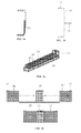
Figure 1 a shows a section of a ring frame made of metal andFigure 1 b shows a section of a ring frame made of a composite manufactured by means of the process object of the present invention. -
Figure 2a shows a perspective view of the first tool used in the process object of the present invention. -
Figure 2b schematically shows the components of the first tool used in the process object of the present invention. -
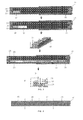
Figure 3 schematically shows the different phases of the step for hot-forming planar laminates of the process object of the present invention. -
Figure 4 schematically shows the cuts made in the planar laminate so as to obtain the laminates with the dimensions required for the preforms with C-and L- shaped sections. -
Figure 5 schematically shows the different phases of the step for forming planar laminates of the process object of the present invention. -
Figure 6 schematically shows the different phases of the step for hot-forming the preforms with C- and L-shaped sections. -
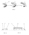
Figure 7 shows schematic section views of the second tool used in the process object of the present invention. -
Figures 8 and 9 show schematic section views of the central module of the first tool. - An embodiment of the process according to the invention for manufacturing aeronautical fuselage ring frame preforms with composites is described below.
- The section to be manufactured is formed by a C shape 11 and by an L-
shaped angle iron 13 made from fabric and reinforced with a unidirectional tape on thelower flange 15 to increase the moment of inertia and therefore the stiffness. Ring frames of up to 8 meters long with radiuses of curvature of up to 250 mm can be obtained with this invention. - Carrying out the process begins with providing the material needed to manufacture the laminates; the patterns obtained from the cutting process are manufactured in groups as per geometries, such that the cutting machine works only once, obtaining the pattern required from each one of them. An identification of each one of the parts is not required by means of this process, and it is only necessary to gradually take the required number of pieces of each geometry to manufacture the laminate.
- For its part, the
laminate tool 21 of the C- and L-shaped preforms (in each case with the suitable dimensions) is provided, coupling theside modules 23 to thecentral module 25.Longitudinal gibs 27 are fixed, positioned on theside modules 23 in the area where the laminating is carried out (any of the twoside modules 23 is suitable for this). - To begin the laminate 41, the hold-down
plate 29 of the top part of thetool 21 is removed. Then the rectangular patterns of the pieces ofmaterial 30 are arranged at +/- 45° between thecentral module 25 and thegibs 27 of theside module 23 chosen for manufacture, longitudinally overlapping the patterns. The measurements of the contour dimensions as well as the displacement, cutting and overlap marks of the layers involved therein are shown by means of laser projectors. In order to integrate the reinforcements and overlap the pieces ofmaterial 30 until obtaining the entire length of the ring frame section, pressure and temperature are applied with aheating head 31 that can shift on guides on the sides of the table 33. The lowering of theheating head 31 above the laminate 41 is done by means of manually controlled pneumatic actuation. The heater can rotate +45°, +90°, -90°,-45° around the Z axis in order to be able to adhere the reinforcements of the unidirectional tape or overlaps, as the case may be. Once the laminate 41 is finished, it is to be cut in the areas marked, identifying each one of the resulting parts and the axes of symmetry with a white marker, thus it is clear that fourring frames - The straight hot-forming of the C- and L-shaped preforms is carried out in the
laminate tool 21 following the steps shown inFigure 5 . First a separating film 53 will be arranged so that the starting laminate 51 (with the dimension required for hot-forming the C- or L-shaped perform involved) does not adhere to the elastic membrane 55 and contaminate the material. Then the hold-down plate 29 is placed, which is quickly anchored through a pneumatic actuator to a projection on thecentral module 25, the cantilever of which overlaps on only a 10 mm longitudinal strip of laminate 41 and presses on it enough so that it is not dragged by the elastic membrane 55. Since the laminate 51 has longitudinal reinforcements with variable thickness in the area to be heated, the hold-downplate 29 must be discontinuous so as to couple to the different heights. Once the hold-downplate 29 is in place, theside modules 23 are carefully removed so as to not drag the previously generated laminate 41, and the ring frame with the elastic membrane 55 is placed. This elastic silicone membrane is vacuum-deformed, withstanding temperatures of 120° as the working temperature, and elongations of the order of 400%. Then with everything assembled, the hot-forming (temperature + vacuum) process is performed. The temperature is applied through the hot-formingtool 21. Thecentral module 25 hasresistors 61 embedded therein to heat the laminate 51. During hot-forming, these resistors heat the horizontal area where the laminate 51 and 5 mm (at most) of the vertical area is supported. To prevent the vertical area from being heated, anFV material 63 is placed in the tool in this area acting as a thermal insulator. The temperature to be reached locally is 100°C (with a tolerance of ± 5°C) for 20 minutes as a reference. The vacuum is carried out through the table 33 of thetool 21, made in aluminum honeycomb panel form, and the vacuum inlets are placed under thecentral module 25, which has longitudinal mortising with transverse bypasses 67. - To carry out the second hot-forming cycle the curved hot-forming tool 55 for the C- and L-shaped preforms is used. The laminates 51 of right angle section obtained in the previous step are placed on the hot-forming component 55 corresponding to the C- and L-shaped preforms, manually deforming them in order to couple them to the male part 55 without the occurrence of creases, first placing the flanges shaped in the previous step into the mortises 59 and then adapting the rest of the laminate to the tool which, in the case of the C-shaped preforms, means that in addition to the curved deformation, the deformation required for hot-forming the other flange must be carried out, using
mortises 60 for that purpose. - Then a separating film is placed on the preforms, making the necessary cuts for the purpose of coupling it perfectly, and this is all held with
elastic strips 71 withfastening clips 73, preventing the occurrence of creases in the radiuses and web. Control thermocouples will be positioned on each one of the preforms, in the middle of the flanges shaped in the first straight hot-forming cycle, introduced in it about 5 mm deep. Finally, the tool 55, formed by aluminum sheet metal 75 on abase sheet metal 77, also of aluminum, will be introduced in the hot-forming machine (temperature + vacuum cycles). - Once the preforms are shaped the excess parts will be cut away.
- If it is necessary in the assembly to couple the outer flange of the ring frame to a planar support, such as the overlay, wedge-shaped accessories can be manufactured which are placed on the ring frames, coupling them to the flanges by means of the application of heat with an iron.
- Now the preforms are ready for carrying out a ring frame of a fully integrated section by means of a process known as RTM injection.
- Any modifications comprised within the scope defined by the following claims can be introduced in the preferred embodiment described above.
Claims (4)
- A process for manufacturing composite ring frames for aeronautical fuselages by means of the application of the RTM technology to two preforms with C- and L-shaped sections, characterized in that said preforms are manufactured using a first tool (21) and a second tool (55) in the following steps:a) Providing the fabric for the preforms in pieces of material (30) cut according to preset patterns;b) Hot-forming planar rectangular laminates (41) placing layers of pieces of material (30) on a first tool (21) in predetermined positions and number and applying pressure and temperature so that the pieces of material (30) adhere to one another in local areas;c) Hot-forming laminates of right angle section (51) from segments of said planar laminates (41) of predetermined dimensions, obtained by means of cutting, on a part of right angle section of the first tool (21), arranging on its top side the part intended for the flange of the preforms with a C- or L-shaped section, holding its longitudinal edge on the first tool (21) and allowing the rest to be free, placing an elastic membrane (55) on the first tool (21) and applying a temperature and vacuum cycle;d) Hot-forming the preforms into a C shape (11) and L shape (13) on a second curved tool (55) by deforming said laminates of right angle section (51) thereon, said deformation including in the case of C-shaped preforms the bending of the second flange, and applying a temperature and vacuum cycle.
- A process for manufacturing composite ring frames for aeronautical fuselages according to claim 1, characterized in that the preset patterns for the pieces of material (30) include rectangular patterns at +/- 45° and unidirectional tape reinforcement for a flange.
- A tool (21) for carrying out steps b) and c) of the process object of claims 1-2, characterized in that it comprises a central module (25) and two side modules (23), which are joined together to carry out step b) and are separated to carry out step c), and heating heads (31) for carrying out the application of pressure and temperature of step b), the central module (25) having heating components (61) inside, vacuum inlets for carrying out step c) and a hold-down plate (29) with a pneumatic actuator arranged on the central module (25) to hold the laminates (51) during step c).
- A tool (55) for carrying out step d) of the process object of claims 1-2, characterized in that it comprises a curved male module (57) with mortises (59, 60) for positioning the flange and flanges, respectively, of the L- or C-shaped laminates (51) and a plurality of elastic strips (71) for holding the laminates during hot-forming.
Applications Claiming Priority (1)
| Application Number | Priority Date | Filing Date | Title |
|---|---|---|---|
| PCT/ES2005/070186 WO2007074179A1 (en) | 2005-12-29 | 2005-12-29 | Method and tools for producing ring frames from a composite material |
Publications (3)
| Publication Number | Publication Date |
|---|---|
| EP1972426A1 true EP1972426A1 (en) | 2008-09-24 |
| EP1972426A4 EP1972426A4 (en) | 2012-12-19 |
| EP1972426B1 EP1972426B1 (en) | 2015-11-11 |
Family
ID=38217702
Family Applications (1)
| Application Number | Title | Priority Date | Filing Date |
|---|---|---|---|
| EP05826212.2A Expired - Lifetime EP1972426B1 (en) | 2005-12-29 | 2005-12-29 | Method and tools for producing ring frames from a composite material |
Country Status (7)
| Country | Link |
|---|---|
| US (1) | US7544261B1 (en) |
| EP (1) | EP1972426B1 (en) |
| CN (1) | CN101448629B (en) |
| BR (1) | BRPI0520815B1 (en) |
| CA (1) | CA2635365C (en) |
| ES (1) | ES2560660T3 (en) |
| WO (1) | WO2007074179A1 (en) |
Cited By (4)
| Publication number | Priority date | Publication date | Assignee | Title |
|---|---|---|---|---|
| DE102011002906A1 (en) * | 2011-01-20 | 2012-07-26 | Cotesa Gmbh | Shaping core used for draping unidirectional unbent fiber layers for producing continuous fiber reinforced component, has flexible soft strips whose bending curvatures are extended along concentric direction |
| WO2013144389A1 (en) * | 2012-03-30 | 2013-10-03 | Industrias Delta Vigo S.L. | Method for obtaining patterns for producing preforms of composite materials |
| US8556213B2 (en) | 2007-09-07 | 2013-10-15 | Airbus Operations S.A.S. | Structural frame made of a composite material and aircraft fuselage comprising such a frame |
| DE102015110195A1 (en) * | 2015-06-24 | 2016-12-29 | Airbus Operations Gmbh | Apparatus and method for forming a semi-finished fiber product |
Families Citing this family (17)
| Publication number | Priority date | Publication date | Assignee | Title |
|---|---|---|---|---|
| US8632653B2 (en) | 2005-05-03 | 2014-01-21 | The Boeing Company | Method of manufacturing curved composite structural elements |
| WO2008104614A1 (en) * | 2007-02-28 | 2008-09-04 | Airbus España, S.L. | Tool and method for producing aircraft ring frames from a composite material |
| US8349105B2 (en) * | 2008-04-17 | 2013-01-08 | The Boeing Company | Curved composite frames and method of making the same |
| US9278484B2 (en) | 2008-04-17 | 2016-03-08 | The Boeing Company | Method and apparatus for producing contoured composite structures and structures produced thereby |
| US9090028B2 (en) | 2008-04-17 | 2015-07-28 | The Boeing Company | Method for producing contoured composite structures and structures produced thereby |
| US8932423B2 (en) * | 2008-04-17 | 2015-01-13 | The Boeing Company | Method for producing contoured composite structures and structures produced thereby |
| CN101283862B (en) * | 2008-05-12 | 2012-03-14 | 杨荣发 | Furniture frame and producing method |
| EP2119679A1 (en) * | 2008-05-16 | 2009-11-18 | 3S Swiss Solar Systems AG | Method for processing a laminate |
| US9387657B2 (en) | 2010-11-12 | 2016-07-12 | The Boeing Company | Method of fabricating a curved composite structure using composite prepreg tape |
| US8551380B2 (en) * | 2010-11-12 | 2013-10-08 | The Boeing Company | Method of laying up prepreg plies on contoured tools using a deformable carrier film |
| US9701067B2 (en) | 2010-11-12 | 2017-07-11 | The Boeing Company | Method of laying up prepreg plies on contoured tools using a deformable carrier film |
| EP3088152B1 (en) * | 2015-04-30 | 2020-04-15 | Airbus Operations, S.L. | Method for manufacturing composite parts and form |
| US11318689B2 (en) | 2018-12-21 | 2022-05-03 | The Boeing Company | Ply transporting and compacting apparatus and method therefor |
| US11305498B2 (en) | 2018-12-21 | 2022-04-19 | The Boeing Company | System and method for fabricating a composite ply layup |
| ES2958761T3 (en) * | 2019-11-13 | 2024-02-14 | Airbus Operations Slu | Device and method of forming a composite laminate to obtain a Z-shaped profile |
| CN111203996B (en) * | 2019-12-13 | 2022-04-19 | 中国航空工业集团公司基础技术研究院 | Preparation equipment and method for prefabricated body with bent section |
| CN111113916A (en) * | 2020-01-02 | 2020-05-08 | 株洲时代新材料科技股份有限公司 | Rail vehicle arc-shaped floor forming method and rail vehicle arc-shaped floor |
Family Cites Families (8)
| Publication number | Priority date | Publication date | Assignee | Title |
|---|---|---|---|---|
| US5546880A (en) * | 1994-12-29 | 1996-08-20 | The Bf Goodrich Company | Annular filamentary structures and methods of making |
| US5648109A (en) * | 1995-05-03 | 1997-07-15 | Massachusetts Institute Of Technology | Apparatus for diaphragm forming |
| GB9828368D0 (en) * | 1998-12-22 | 1999-02-17 | British Aerospace | Forming reinforcing components |
| ES2185443B1 (en) * | 2000-03-07 | 2004-09-01 | Airbus España S.L. | PROCEDURE FOR MANUFACTURING OF PREPARED PARTS IN COMPOSITE MATERIAL WITH RIGIDIZERS APPLIED IN FRESH STATE. |
| US7056402B2 (en) * | 2000-11-21 | 2006-06-06 | Eads Deutschland Gmbh | Technical production method, tension module and sewing material holder for creating textile preforms for the production of fibre-reinforced plastic components |
| ES2205961B2 (en) * | 2001-02-13 | 2005-03-01 | Eads Construcciones Aeronauticas, S.A. | PROCEDURE FOR THE MANUFACTURE OF COMPOSITE MATERIAL ELEMENTS THROUGH THE COENCOLATE TECHNOLOGY. |
| US20040074578A1 (en) * | 2002-10-16 | 2004-04-22 | Kenneth Dewing | Internal buttress for tire bead retention |
| EP1547756A1 (en) * | 2003-12-24 | 2005-06-29 | Airbus UK Limited | Method of manufacturing aircraft components |
-
2005
- 2005-12-29 WO PCT/ES2005/070186 patent/WO2007074179A1/en not_active Ceased
- 2005-12-29 CA CA2635365A patent/CA2635365C/en not_active Expired - Fee Related
- 2005-12-29 ES ES05826212.2T patent/ES2560660T3/en not_active Expired - Lifetime
- 2005-12-29 BR BRPI0520815A patent/BRPI0520815B1/en not_active IP Right Cessation
- 2005-12-29 CN CN200580052558.3A patent/CN101448629B/en not_active Expired - Fee Related
- 2005-12-29 EP EP05826212.2A patent/EP1972426B1/en not_active Expired - Lifetime
-
2006
- 2006-02-27 US US11/363,496 patent/US7544261B1/en active Active
Non-Patent Citations (2)
| Title |
|---|
| No further relevant documents disclosed * |
| See also references of WO2007074179A1 * |
Cited By (7)
| Publication number | Priority date | Publication date | Assignee | Title |
|---|---|---|---|---|
| US8556213B2 (en) | 2007-09-07 | 2013-10-15 | Airbus Operations S.A.S. | Structural frame made of a composite material and aircraft fuselage comprising such a frame |
| DE102011002906A1 (en) * | 2011-01-20 | 2012-07-26 | Cotesa Gmbh | Shaping core used for draping unidirectional unbent fiber layers for producing continuous fiber reinforced component, has flexible soft strips whose bending curvatures are extended along concentric direction |
| DE102011002906B4 (en) * | 2011-01-20 | 2012-11-29 | Cotesa Gmbh | Forming core and process for draping unidirectional 0 ° fiber layers |
| WO2013144389A1 (en) * | 2012-03-30 | 2013-10-03 | Industrias Delta Vigo S.L. | Method for obtaining patterns for producing preforms of composite materials |
| ES2428588R1 (en) * | 2012-03-30 | 2014-02-04 | Industrias Delta Vigo S.L. | Procedure for obtaining standards for the manufacture of preforms of composite materials |
| DE102015110195A1 (en) * | 2015-06-24 | 2016-12-29 | Airbus Operations Gmbh | Apparatus and method for forming a semi-finished fiber product |
| US10144170B2 (en) | 2015-06-24 | 2018-12-04 | Airbus Operations Gmbh | Device and method for shaping a semi-finished fiber product |
Also Published As
| Publication number | Publication date |
|---|---|
| BRPI0520815B1 (en) | 2016-12-20 |
| EP1972426A4 (en) | 2012-12-19 |
| CA2635365A1 (en) | 2007-07-05 |
| US7544261B1 (en) | 2009-06-09 |
| WO2007074179A1 (en) | 2007-07-05 |
| CN101448629A (en) | 2009-06-03 |
| BRPI0520815A2 (en) | 2009-06-09 |
| ES2560660T3 (en) | 2016-02-22 |
| CA2635365C (en) | 2014-01-28 |
| CN101448629B (en) | 2011-08-17 |
| EP1972426B1 (en) | 2015-11-11 |
| US20090139644A1 (en) | 2009-06-04 |
Similar Documents
| Publication | Publication Date | Title |
|---|---|---|
| US7544261B1 (en) | Process and tools for manufacturing composite ring frames | |
| EP1231046B1 (en) | Method for manufacturing elements of composite materials by the cobonding technique | |
| US9096021B2 (en) | Method and shaping device for producing a composite fiber component for air and space travel | |
| CN111716758B (en) | Co-consolidation tools and related methods | |
| JP5063707B2 (en) | Thermoplastic composite part having integral metal fitting and method for producing the same | |
| EP1134070B1 (en) | Process for manufacturing pre-cured parts of composite material with green-applied stiffeners | |
| EP3115185B1 (en) | Reducing wrinkling of contoured hat stiffeners formed from a single composite charge | |
| CN103402739B (en) | For manufacturing the method and apparatus of profile composite construction and consequent structure | |
| JP5184542B2 (en) | Method for manufacturing curved thermoplastic composite parts | |
| EP1972427B1 (en) | Method for producing panels of composite materials with u-shaped stiffening elements | |
| EP2357075B1 (en) | Method for manufacturing a complex-geometry panel with pre-impregnated composite material | |
| US20140318693A1 (en) | Staged cocuring of composite structures | |
| EP2835252A1 (en) | Tooling and method for consolidating highly integrated composite structures | |
| EP3205491B1 (en) | Method for manufacturing a stiffened panel made from composite material | |
| RU2761851C2 (en) | Methods for manufacturing curve omega-stringers and z-shape stringers of composite material and manufacturing reinforced panel of composite material with curvature | |
| RU2390417C2 (en) | Method and hardware for production of composite circular frames | |
| EP3744511B1 (en) | Composite forming station | |
| KR102307860B1 (en) | Warm roll pressurising device for attaching an carbon fiber reinforced plastic sheet on steel plate | |
| CN112793279A (en) | Apparatus and method for forming composite laminates to obtain Z-shaped profiles | |
| HK1139104B (en) | Thermoplastic composite parts having integrated metal fittings and method of making the same | |
| HK1133232B (en) | Method for fabricating curved thermoplastic composite parts |
Legal Events
| Date | Code | Title | Description |
|---|---|---|---|
| PUAI | Public reference made under article 153(3) epc to a published international application that has entered the european phase |
Free format text: ORIGINAL CODE: 0009012 |
|
| 17P | Request for examination filed |
Effective date: 20080728 |
|
| AK | Designated contracting states |
Kind code of ref document: A1 Designated state(s): AT BE BG CH CY CZ DE DK EE ES FI FR GB GR HU IE IS IT LI LT LU LV MC NL PL PT RO SE SI SK TR |
|
| RIN1 | Information on inventor provided before grant (corrected) |
Inventor name: NOGUEROLES VINES, PEDROAIRBUS ESPANA, S.L., Inventor name: GARCIA GARCIA, AQUILINO Inventor name: MARTIN MARTIN, JESUS MANUELAIRBUS ESPANA, S.L., |
|
| RAP1 | Party data changed (applicant data changed or rights of an application transferred) |
Owner name: AIRBUS OPERATIONS S.L. |
|
| DAX | Request for extension of the european patent (deleted) | ||
| A4 | Supplementary search report drawn up and despatched |
Effective date: 20121120 |
|
| 17Q | First examination report despatched |
Effective date: 20140131 |
|
| RIC1 | Information provided on ipc code assigned before grant |
Ipc: B29C 70/20 20060101ALI20150504BHEP Ipc: B29B 11/16 20060101ALI20150504BHEP Ipc: B29C 70/22 20060101AFI20150504BHEP Ipc: B29C 70/44 20060101ALI20150504BHEP |
|
| GRAP | Despatch of communication of intention to grant a patent |
Free format text: ORIGINAL CODE: EPIDOSNIGR1 |
|
| INTG | Intention to grant announced |
Effective date: 20150624 |
|
| GRAS | Grant fee paid |
Free format text: ORIGINAL CODE: EPIDOSNIGR3 |
|
| GRAA | (expected) grant |
Free format text: ORIGINAL CODE: 0009210 |
|
| AK | Designated contracting states |
Kind code of ref document: B1 Designated state(s): AT BE BG CH CY CZ DE DK EE ES FI FR GB GR HU IE IS IT LI LT LU LV MC NL PL PT RO SE SI SK TR |
|
| REG | Reference to a national code |
Ref country code: GB Ref legal event code: FG4D |
|
| REG | Reference to a national code |
Ref country code: CH Ref legal event code: EP |
|
| REG | Reference to a national code |
Ref country code: IE Ref legal event code: FG4D |
|
| REG | Reference to a national code |
Ref country code: AT Ref legal event code: REF Ref document number: 760229 Country of ref document: AT Kind code of ref document: T Effective date: 20151215 |
|
| REG | Reference to a national code |
Ref country code: FR Ref legal event code: PLFP Year of fee payment: 11 |
|
| REG | Reference to a national code |
Ref country code: DE Ref legal event code: R096 Ref document number: 602005047912 Country of ref document: DE |
|
| REG | Reference to a national code |
Ref country code: ES Ref legal event code: FG2A Ref document number: 2560660 Country of ref document: ES Kind code of ref document: T3 Effective date: 20160222 |
|
| REG | Reference to a national code |
Ref country code: LT Ref legal event code: MG4D |
|
| REG | Reference to a national code |
Ref country code: NL Ref legal event code: MP Effective date: 20160211 |
|
| REG | Reference to a national code |
Ref country code: AT Ref legal event code: MK05 Ref document number: 760229 Country of ref document: AT Kind code of ref document: T Effective date: 20151111 |
|
| PG25 | Lapsed in a contracting state [announced via postgrant information from national office to epo] |
Ref country code: LT Free format text: LAPSE BECAUSE OF FAILURE TO SUBMIT A TRANSLATION OF THE DESCRIPTION OR TO PAY THE FEE WITHIN THE PRESCRIBED TIME-LIMIT Effective date: 20151111 Ref country code: NL Free format text: LAPSE BECAUSE OF FAILURE TO SUBMIT A TRANSLATION OF THE DESCRIPTION OR TO PAY THE FEE WITHIN THE PRESCRIBED TIME-LIMIT Effective date: 20151111 Ref country code: IT Free format text: LAPSE BECAUSE OF FAILURE TO SUBMIT A TRANSLATION OF THE DESCRIPTION OR TO PAY THE FEE WITHIN THE PRESCRIBED TIME-LIMIT Effective date: 20151111 Ref country code: IS Free format text: LAPSE BECAUSE OF FAILURE TO SUBMIT A TRANSLATION OF THE DESCRIPTION OR TO PAY THE FEE WITHIN THE PRESCRIBED TIME-LIMIT Effective date: 20160311 |
|
| PG25 | Lapsed in a contracting state [announced via postgrant information from national office to epo] |
Ref country code: BE Free format text: LAPSE BECAUSE OF NON-PAYMENT OF DUE FEES Effective date: 20151231 Ref country code: PL Free format text: LAPSE BECAUSE OF FAILURE TO SUBMIT A TRANSLATION OF THE DESCRIPTION OR TO PAY THE FEE WITHIN THE PRESCRIBED TIME-LIMIT Effective date: 20151111 Ref country code: GR Free format text: LAPSE BECAUSE OF FAILURE TO SUBMIT A TRANSLATION OF THE DESCRIPTION OR TO PAY THE FEE WITHIN THE PRESCRIBED TIME-LIMIT Effective date: 20160212 Ref country code: SE Free format text: LAPSE BECAUSE OF FAILURE TO SUBMIT A TRANSLATION OF THE DESCRIPTION OR TO PAY THE FEE WITHIN THE PRESCRIBED TIME-LIMIT Effective date: 20151111 Ref country code: LV Free format text: LAPSE BECAUSE OF FAILURE TO SUBMIT A TRANSLATION OF THE DESCRIPTION OR TO PAY THE FEE WITHIN THE PRESCRIBED TIME-LIMIT Effective date: 20151111 Ref country code: AT Free format text: LAPSE BECAUSE OF FAILURE TO SUBMIT A TRANSLATION OF THE DESCRIPTION OR TO PAY THE FEE WITHIN THE PRESCRIBED TIME-LIMIT Effective date: 20151111 Ref country code: FI Free format text: LAPSE BECAUSE OF FAILURE TO SUBMIT A TRANSLATION OF THE DESCRIPTION OR TO PAY THE FEE WITHIN THE PRESCRIBED TIME-LIMIT Effective date: 20151111 Ref country code: PT Free format text: LAPSE BECAUSE OF FAILURE TO SUBMIT A TRANSLATION OF THE DESCRIPTION OR TO PAY THE FEE WITHIN THE PRESCRIBED TIME-LIMIT Effective date: 20160311 |
|
| PG25 | Lapsed in a contracting state [announced via postgrant information from national office to epo] |
Ref country code: CZ Free format text: LAPSE BECAUSE OF FAILURE TO SUBMIT A TRANSLATION OF THE DESCRIPTION OR TO PAY THE FEE WITHIN THE PRESCRIBED TIME-LIMIT Effective date: 20151111 |
|
| REG | Reference to a national code |
Ref country code: CH Ref legal event code: PL |
|
| REG | Reference to a national code |
Ref country code: DE Ref legal event code: R097 Ref document number: 602005047912 Country of ref document: DE |
|
| PG25 | Lapsed in a contracting state [announced via postgrant information from national office to epo] |
Ref country code: RO Free format text: LAPSE BECAUSE OF FAILURE TO SUBMIT A TRANSLATION OF THE DESCRIPTION OR TO PAY THE FEE WITHIN THE PRESCRIBED TIME-LIMIT Effective date: 20151111 Ref country code: DK Free format text: LAPSE BECAUSE OF FAILURE TO SUBMIT A TRANSLATION OF THE DESCRIPTION OR TO PAY THE FEE WITHIN THE PRESCRIBED TIME-LIMIT Effective date: 20151111 Ref country code: SK Free format text: LAPSE BECAUSE OF FAILURE TO SUBMIT A TRANSLATION OF THE DESCRIPTION OR TO PAY THE FEE WITHIN THE PRESCRIBED TIME-LIMIT Effective date: 20151111 Ref country code: EE Free format text: LAPSE BECAUSE OF FAILURE TO SUBMIT A TRANSLATION OF THE DESCRIPTION OR TO PAY THE FEE WITHIN THE PRESCRIBED TIME-LIMIT Effective date: 20151111 |
|
| PLBE | No opposition filed within time limit |
Free format text: ORIGINAL CODE: 0009261 |
|
| STAA | Information on the status of an ep patent application or granted ep patent |
Free format text: STATUS: NO OPPOSITION FILED WITHIN TIME LIMIT |
|
| REG | Reference to a national code |
Ref country code: IE Ref legal event code: MM4A |
|
| PG25 | Lapsed in a contracting state [announced via postgrant information from national office to epo] |
Ref country code: MC Free format text: LAPSE BECAUSE OF FAILURE TO SUBMIT A TRANSLATION OF THE DESCRIPTION OR TO PAY THE FEE WITHIN THE PRESCRIBED TIME-LIMIT Effective date: 20151111 |
|
| 26N | No opposition filed |
Effective date: 20160812 |
|
| PG25 | Lapsed in a contracting state [announced via postgrant information from national office to epo] |
Ref country code: CH Free format text: LAPSE BECAUSE OF NON-PAYMENT OF DUE FEES Effective date: 20151231 Ref country code: IE Free format text: LAPSE BECAUSE OF NON-PAYMENT OF DUE FEES Effective date: 20151229 Ref country code: LI Free format text: LAPSE BECAUSE OF NON-PAYMENT OF DUE FEES Effective date: 20151231 |
|
| PG25 | Lapsed in a contracting state [announced via postgrant information from national office to epo] |
Ref country code: SI Free format text: LAPSE BECAUSE OF FAILURE TO SUBMIT A TRANSLATION OF THE DESCRIPTION OR TO PAY THE FEE WITHIN THE PRESCRIBED TIME-LIMIT Effective date: 20151111 |
|
| REG | Reference to a national code |
Ref country code: FR Ref legal event code: PLFP Year of fee payment: 12 |
|
| PG25 | Lapsed in a contracting state [announced via postgrant information from national office to epo] |
Ref country code: BE Free format text: LAPSE BECAUSE OF FAILURE TO SUBMIT A TRANSLATION OF THE DESCRIPTION OR TO PAY THE FEE WITHIN THE PRESCRIBED TIME-LIMIT Effective date: 20151111 |
|
| PG25 | Lapsed in a contracting state [announced via postgrant information from national office to epo] |
Ref country code: HU Free format text: LAPSE BECAUSE OF FAILURE TO SUBMIT A TRANSLATION OF THE DESCRIPTION OR TO PAY THE FEE WITHIN THE PRESCRIBED TIME-LIMIT; INVALID AB INITIO Effective date: 20051229 Ref country code: BG Free format text: LAPSE BECAUSE OF FAILURE TO SUBMIT A TRANSLATION OF THE DESCRIPTION OR TO PAY THE FEE WITHIN THE PRESCRIBED TIME-LIMIT Effective date: 20151111 |
|
| PG25 | Lapsed in a contracting state [announced via postgrant information from national office to epo] |
Ref country code: CY Free format text: LAPSE BECAUSE OF FAILURE TO SUBMIT A TRANSLATION OF THE DESCRIPTION OR TO PAY THE FEE WITHIN THE PRESCRIBED TIME-LIMIT Effective date: 20151111 |
|
| PG25 | Lapsed in a contracting state [announced via postgrant information from national office to epo] |
Ref country code: TR Free format text: LAPSE BECAUSE OF FAILURE TO SUBMIT A TRANSLATION OF THE DESCRIPTION OR TO PAY THE FEE WITHIN THE PRESCRIBED TIME-LIMIT Effective date: 20151111 |
|
| PG25 | Lapsed in a contracting state [announced via postgrant information from national office to epo] |
Ref country code: LU Free format text: LAPSE BECAUSE OF NON-PAYMENT OF DUE FEES Effective date: 20151229 |
|
| REG | Reference to a national code |
Ref country code: FR Ref legal event code: PLFP Year of fee payment: 13 |
|
| PGFP | Annual fee paid to national office [announced via postgrant information from national office to epo] |
Ref country code: DE Payment date: 20191210 Year of fee payment: 15 |
|
| PGFP | Annual fee paid to national office [announced via postgrant information from national office to epo] |
Ref country code: FR Payment date: 20191220 Year of fee payment: 15 |
|
| PGFP | Annual fee paid to national office [announced via postgrant information from national office to epo] |
Ref country code: GB Payment date: 20191220 Year of fee payment: 15 Ref country code: ES Payment date: 20200121 Year of fee payment: 15 |
|
| REG | Reference to a national code |
Ref country code: DE Ref legal event code: R119 Ref document number: 602005047912 Country of ref document: DE |
|
| GBPC | Gb: european patent ceased through non-payment of renewal fee |
Effective date: 20201229 |
|
| PG25 | Lapsed in a contracting state [announced via postgrant information from national office to epo] |
Ref country code: FR Free format text: LAPSE BECAUSE OF NON-PAYMENT OF DUE FEES Effective date: 20201231 |
|
| PG25 | Lapsed in a contracting state [announced via postgrant information from national office to epo] |
Ref country code: DE Free format text: LAPSE BECAUSE OF NON-PAYMENT OF DUE FEES Effective date: 20210701 Ref country code: GB Free format text: LAPSE BECAUSE OF NON-PAYMENT OF DUE FEES Effective date: 20201229 |
|
| REG | Reference to a national code |
Ref country code: ES Ref legal event code: FD2A Effective date: 20220222 |
|
| PG25 | Lapsed in a contracting state [announced via postgrant information from national office to epo] |
Ref country code: ES Free format text: LAPSE BECAUSE OF NON-PAYMENT OF DUE FEES Effective date: 20201230 |