EP1972266A1 - Fundus camera - Google Patents
Fundus camera Download PDFInfo
- Publication number
- EP1972266A1 EP1972266A1 EP08152140A EP08152140A EP1972266A1 EP 1972266 A1 EP1972266 A1 EP 1972266A1 EP 08152140 A EP08152140 A EP 08152140A EP 08152140 A EP08152140 A EP 08152140A EP 1972266 A1 EP1972266 A1 EP 1972266A1
- Authority
- EP
- European Patent Office
- Prior art keywords
- photographing
- fundus
- alignment
- display
- image
- Prior art date
- Legal status (The legal status is an assumption and is not a legal conclusion. Google has not performed a legal analysis and makes no representation as to the accuracy of the status listed.)
- Withdrawn
Links
- 230000003287 optical effect Effects 0.000 claims abstract description 122
- 238000001514 detection method Methods 0.000 claims abstract description 11
- 230000007246 mechanism Effects 0.000 claims abstract description 10
- 230000000007 visual effect Effects 0.000 claims abstract description 10
- 230000002093 peripheral effect Effects 0.000 claims description 6
- 210000000695 crystalline len Anatomy 0.000 description 22
- 238000005286 illumination Methods 0.000 description 21
- 210000001747 pupil Anatomy 0.000 description 9
- 210000004087 cornea Anatomy 0.000 description 4
- 210000003733 optic disk Anatomy 0.000 description 3
- 230000035945 sensitivity Effects 0.000 description 3
- 230000005540 biological transmission Effects 0.000 description 2
- 230000007423 decrease Effects 0.000 description 2
- 229910052736 halogen Inorganic materials 0.000 description 2
- 150000002367 halogens Chemical class 0.000 description 2
- 230000004048 modification Effects 0.000 description 2
- 238000012986 modification Methods 0.000 description 2
- 230000015572 biosynthetic process Effects 0.000 description 1
- 239000000470 constituent Substances 0.000 description 1
- 210000003128 head Anatomy 0.000 description 1
- 239000004973 liquid crystal related substance Substances 0.000 description 1
Images


Classifications
-
- A—HUMAN NECESSITIES
- A61—MEDICAL OR VETERINARY SCIENCE; HYGIENE
- A61B—DIAGNOSIS; SURGERY; IDENTIFICATION
- A61B3/00—Apparatus for testing the eyes; Instruments for examining the eyes
- A61B3/10—Objective types, i.e. instruments for examining the eyes independent of the patients' perceptions or reactions
- A61B3/12—Objective types, i.e. instruments for examining the eyes independent of the patients' perceptions or reactions for looking at the eye fundus, e.g. ophthalmoscopes
-
- A—HUMAN NECESSITIES
- A61—MEDICAL OR VETERINARY SCIENCE; HYGIENE
- A61B—DIAGNOSIS; SURGERY; IDENTIFICATION
- A61B3/00—Apparatus for testing the eyes; Instruments for examining the eyes
- A61B3/0016—Operational features thereof
- A61B3/0041—Operational features thereof characterised by display arrangements
-
- A—HUMAN NECESSITIES
- A61—MEDICAL OR VETERINARY SCIENCE; HYGIENE
- A61B—DIAGNOSIS; SURGERY; IDENTIFICATION
- A61B3/00—Apparatus for testing the eyes; Instruments for examining the eyes
- A61B3/0091—Fixation targets for viewing direction
-
- A—HUMAN NECESSITIES
- A61—MEDICAL OR VETERINARY SCIENCE; HYGIENE
- A61B—DIAGNOSIS; SURGERY; IDENTIFICATION
- A61B3/00—Apparatus for testing the eyes; Instruments for examining the eyes
- A61B3/10—Objective types, i.e. instruments for examining the eyes independent of the patients' perceptions or reactions
- A61B3/14—Arrangements specially adapted for eye photography
- A61B3/15—Arrangements specially adapted for eye photography with means for aligning, spacing or blocking spurious reflection ; with means for relaxing
- A61B3/152—Arrangements specially adapted for eye photography with means for aligning, spacing or blocking spurious reflection ; with means for relaxing for aligning
-
- A—HUMAN NECESSITIES
- A61—MEDICAL OR VETERINARY SCIENCE; HYGIENE
- A61B—DIAGNOSIS; SURGERY; IDENTIFICATION
- A61B3/00—Apparatus for testing the eyes; Instruments for examining the eyes
- A61B3/0008—Apparatus for testing the eyes; Instruments for examining the eyes provided with illuminating means
-
- A—HUMAN NECESSITIES
- A61—MEDICAL OR VETERINARY SCIENCE; HYGIENE
- A61B—DIAGNOSIS; SURGERY; IDENTIFICATION
- A61B3/00—Apparatus for testing the eyes; Instruments for examining the eyes
- A61B3/0075—Apparatus for testing the eyes; Instruments for examining the eyes provided with adjusting devices, e.g. operated by control lever
-
- A—HUMAN NECESSITIES
- A61—MEDICAL OR VETERINARY SCIENCE; HYGIENE
- A61B—DIAGNOSIS; SURGERY; IDENTIFICATION
- A61B3/00—Apparatus for testing the eyes; Instruments for examining the eyes
- A61B3/10—Objective types, i.e. instruments for examining the eyes independent of the patients' perceptions or reactions
- A61B3/14—Arrangements specially adapted for eye photography
- A61B3/145—Arrangements specially adapted for eye photography by video means
Definitions
- the present invention relates to a fundus camera which photographs a fundus of an examinee's eye.
- a fundus camera which changes a display position of a reticle mark that defines an alignment reference in accordance with a presenting position of a fixation target on which an examinee's eye is fixated (see Japanese Patent Application Unexamined Publication Heill-4808 ).
- the display position of the reticle mark is changed so that a photographing optical axis of the fundus camera is aligned with the pupil center in accordance with the presenting position of the fixation target in order to prevent fundus illumination light from being blocked by an iris of the eye.
- the alignment reference position such that a preferable photographing image of the fundus can be obtained differs with a pupil diameter, a corneal shape or other factors of the eye.
- An object of the invention is to overcome the problems described above and to provide a fundus camera which is capable of preferably performing photographing of the periphery of a fundus of an examinee's eye irrespective of the state of the eye.
- a fundus camera comprises a photographing optical system having a photographing optical axis, for photographing a fundus of an examinee's eye, a fundus observation optical system having an image-pickup element which picks up an observation image of the fundus of the eye, an alignment target projection optical system for projecting an alignment target onto an anterior segment of the eye, an alignment target image detection optical system having a photodetector which detects an image of the alignment target, a photographing unit which houses the photographing optical system, the fundus observation optical system, the alignment target projection optical system and the alignment target image detection optical system, a moving mechanism which moves the photographing unit in order to perform alignment of the photographing optical axis so as to have a predetermined positional relationship with the eye, a fixation target presenting system for presenting a fixation target for guiding a direction of a visual line of the eye, a presenting position of the fixation target being arranged to be selectable or changeable, a display
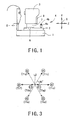
- Fig. 1 is a view showing a schematic configuration of a fundus camera according to a preferred embodiment of the present invention.
- the fundus camera comprises a base 1, a mobile base 2 movable in a right/left direction (hereinafter referred to as an "X-direction") and a back/forth direction (hereinafter referred to as a "Z-direction") with reference to the base 1 through tilting operation of a joystick 4, a photographing unit 3 movable in the right/left direction, an up/down direction (hereinafter referred to as a "Y-direction”), and the back/forth direction with reference to the mobile base 2 under control of a controller 80 to be described later, and a face support unit 5 fixedly provided on the base 1 for supporting a face (a head) of an examinee.
- Moving units 6 and 7 include a Y table movable in the Y-direction, a Z table movable in the Z-direction which is placed on the Y table, and an X table movable in the X-direction which is placed on the Z table, and the photographing unit 3 is placed on the X table.
- the moving unit 7 moves the X and Z tables individually by a motor and other moving mechanisms so as to move the photographing unit 3 in the X-direction and/or the Y-direction.
- the moving unit 6 moves the Y table by a motor and other moving mechanisms so as to move the photographing unit 3 in the Y-direction.
- a known mechanism may be used for the moving mechanisms as the moving units 6 and 7, a known mechanism may be used.
- the photographing unit 3 is moved in the Y-direction also by driving of the moving unit 6 through rotational operation of a rotating knob 4a of the joystick 1.
- a monitor (a display) 8 which displays images including an observation image of an anterior segment of an examinee's eye, an observation image of a fundus of the eye, and a photographing image of the fundus is provided on the examiner's side of the photographing unit 3.
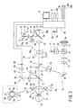
- Fig. 2 is a view showing a schematic configuration of an optical system and a control system housed in the photographing unit 3.
- the optical system comprises an illumination optical system 10, a fundus observation/photographing optical system 30, an alignment target projection optical system 50, an anterior-segment observation optical system 60 and a fixation target presenting optical system 70.
- the illumination optical system 10 comprises an illumination optical system for fundus observation and an illumination optical system for photographing.
- Illumination light emitted from an illumination light source 11 for fundus observation such as a halogen light is made into infrared illumination light by an infrared transmission filter 12 which transmits infrared light with a wavelength of less than about 900 nm, and is reflected by a dichroic mirror 16 via a condenser lens 13.
- the dichroic mirror 16 has a wavelength-selecting property of reflecting infrared light and transmitting visible light.
- the infrared illumination light reflected by the dichroic mirror 16 passes through a ring slit plate 17, a relay lens 18, a total reflection mirror 19, a black dot plate 20 having a black dot at its center and a relay lens 21, and is reflected by an apertured mirror 22 and is projected onto a fundus Ef of an examinee's eye E via an objective lens 25.
- an infrared light source such as an infrared light-emitting diode may be used instead of the light source 11 such as the halogen light and the infrared transmission filter 12.
- Visible illumination light emitted from a visible illumination light source 14 for photographing passes through a condenser lens 15 and is transmitted through the dichroic mirror 16 and is projected onto the fundus Ef via the ring slit plate 17 to the objective lens 25.
- the fundus observation/photographing optical system 30 comprises a fundus observation optical system 30a and a photographing optical system 30b.
- the infrared light and the visible light reflected from the fundus Ef pass through the objective lens 25, an aperture 22a in the apertured mirror 22, a photographing diaphragm 31 placed in the vicinity of the aperture 22a and a focusing lens 32 and enter an image forming lens 33.
- the photographing diaphragm 31 is placed in a position substantially conjugate with a pupil of the eye E with reference to the objective lens 25.
- the focusing lens 32 is placed so as to be movable by a moving unit 49 consisting of a moving mechanism such as a motor in a direction of an optical axis L1 of the fundus observation/photographing optical system 30 (the objective lens 25).
- a movable total reflection mirror 34 is placed so as to be insertable into/removable from an optical path of the fundus observation/photographing optical system 30 by an inserting/removing unit 39 consisting of an inserting/removing mechanism such as a motor, and is removed from the optical path at the time of photographing.
- the visible reflection light is photo-received on a CCD camera (an image-pickup element) 35 for photographing having sensitivity to a visible range and forms an image of the fundus Ef (a fundus photographing image).
- a CCD camera an image-pickup element
- the infrared reflection light reflected by the mirror 34 is reflected by a dichroic mirror 37
- a CCD camera an image-pickup element 38 for fundus observation having sensitivity to an infrared range via a relay lens 36 and forms an image of the fundus Ef (a fundus observation image).
- the dichroic mirror 37 has a wavelength-selecting property of reflecting infrared light and transmitting visible light.
- a movable dichroic mirror 24 that defines an optical path dividing member is placed so as to be insertable into/removable from an optical path between the objective lens 25 and the apertured mirror 22 (the photographing diaphragm 31) by an inserting/removing unit 66 consisting of an inserting/removing mechanism such as a motor, and is removed from the optical path at the time of photographing.
- the dichroic mirror 24 has a wavelength-selecting property of reflecting infrared light with a wavelength of about 900 nm or more from an infrared illumination light source 58 for anterior-segment observation and the alignment target projection optical system 50 to be described later, and transmitting the infrared light with the wavelength of less than about 900 nmfrom the illumination optical system for fundus observation.
- the alignment target projection optical system 50 comprises two first projection optical systems in a pair which have optical axes placed so as to be laterally symmetrical with respect to the optical axis L1, and six second projection optical systems in pairs which have optical axes placed so as to be laterally symmetrical with respect to the optical axis L1.
- Each of the two first projection optical systems includes an infrared light source 51 such as an infrared light-emitting diode which emits the infrared light with the wavelength of about 900 nm or more and a collimating lens 52 and projects infrared target light at an infinite distance (projects an alignment target at an infinite distance) onto an anterior segment (a cornea Ec) of the eye E with substantially parallel light.
- an infrared light source 51 such as an infrared light-emitting diode which emits the infrared light with the wavelength of about 900 nm or more
- a collimating lens 52 projects infrared target light at an infinite distance (projects an alignment target at an infinite distance) onto an anterior segment (a cornea Ec) of the eye E with substantially parallel light.
- each of the six second projection optical systems includes an infrared light source 53 such as an infrared light-emitting diode which emits the infrared light with the wavelength of about 900 nm or more, and projects infrared target light at a finite distance (projects an alignment target at a finite distance) onto the anterior segment (the cornea Ec) of the eye E with divergent light.
- the first projection optical systems and the second projection optical systems are placed at intervals of 45° each other on a concentric circle having the optical axis L1 as its center (e.g., a concentric circle of 3-mm radius).
- Infrared illumination light emitted from the infrared illumination light source 58 for anterior-segment observation such as an infrared light-emitting diode which emits the infrared light with the wavelength of about 900 nm or more is reflected by the anterior segment of the eye E and the dichroic mirror 24 inserted into the optical path, is photo-received on a CCD camera (an image-pickup element) 65 for anterior-segment observation having sensitivity to an infrared range via a field lens 61, a total reflection mirror 62, a diaphragm 63 and a relay lens 64, and forms an image of the anterior segment of the eye E (an anterior-segment observation image).
- a CCD camera an image-pickup element
- the CCD camera 65 doubles as image-pickup means for alignment target image detection (i.e., the anterior-segment observation optical system 60 doubles as an alignment target image detection optical system), and picks up the anterior-segment image formed by the light source 58 and images of the alignment targets formed by the alignment target projection optical system 50.
- Red fixation target light emitted from a fixation target light source (a fixation lamp) 74 such as a red light-emitting diode passes through an aperture in a shielding plate 72 and a relay lens 75 and is transmitted through the dichroic mirror 37.
- the red fixation target light transmitted through the dichroic mirror 37 is reflected by the dichroic mirror 34 inserted into the optical path, passes through the image forming lens 33 to the objective lens 25, and is projected onto the fundus Ef (i.e., a fixation target is projected thereonto).
- the shielding plate 72 has apertures 71a to 71h, one of which is placed in such a position in front of the light source 74 that is not on an optical axis L2 coaxial with the optical axis L1 by being rotated by a motor 73.
- one of eight fixation target presenting positions is selected by selecting one of the apertures 71a to 71h.
- a fixation target presenting position 91L (a standard position in photographing the left eye) corresponding to the aperture 71a is selected when photographing the vicinity of a posterior pole area (a center port ion) of the fundus of the left eye which includes a macular spot and an optic papilla in a balanced manner so as to be the center of the image.
- a fixation target presenting position 91R (a standard position in photographing the right eye) corresponding to the aperture 71b is selected when photographing the vicinity of a posterior pole area (a center portion) of the fundus of the right eye including a macular spot and an optic papilla in a balanced manner so as to be the center of the image.
- fixation target presenting positions 92 to 97 corresponding to the apertures 71c to 71h are selected when photographing peripheral areas (peripheral portions) of the fundus.
- Image signals outputted from the CCD cameras 65, 38 and 35 are inputted to the controller 80.
- the controller 80 detects the alignment target images based on the image signal from the CCD camera 65 and obtains an alignment deviation amount of the optical axis L1 (the photographing unit 3) with respect to the eye E in the X- and Y-directions .
- the controller 80 is connected to the monitor 8 and performs a display control of the monitor 8. For example, both at the time of displaying the anterior-segment observation image by the CCD camera 65 (see Figs. 4A and 4B ) and at the time of displaying the fundus observation image by the CCD camera 38 (see Figs.
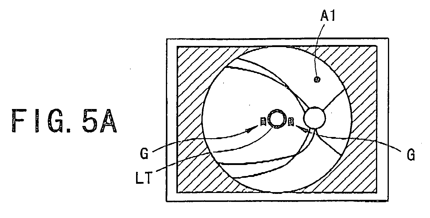
- the controller 80 controls to electrically form and display a reticle mark LT that defines an alignment reference in a predetermined position on a screen of the monitor 8 while controlling to electrically form and display on the screen of the monitor 8 an alignment mark A1 of which a relative distance from the reticle mark LT varies in accordance with the alignment deviation amount in the X- and Y-directions obtained based on the image signal from the CCD camera 65.
- the controller 80 is connected with the moving units 6, 7 and 49, the inserting/removing units 39 and 66, the rotation knob 4a, a photographing switch 4b, a switch unit 84 including various switches, a memory 85, the light sources, and other constituent elements (in Fig. 2 , a part of connection lines are not shown).
- the switch unit 84 includes a focusing switch 84a, a fixation target presenting position changing switch 84b and other switches.
- the face of the examinee is supported by the face support unit 5.
- the fixation target presenting position 91R shown in Fig. 3 is selected through operation of the switch 84b.
- the dichroic mirror 24 has been already inserted into the optical path, and the anterior-segment observation image picked up by the CCD camera 65 is displayed (appears) on the monitor 8.
- the controller 80 controls to electrically form and display in the center of the screen of the monitor 8 the reticle mark LT and a circular mark P indicating the minimum pupil diameter of photographing.
- the photographing unit 3 is moved in the X-direction and/or the Y-direction so that the anterior-segment observation image is placed in the center of the screen of the monitor 8. In addition, the photographing unit 3 is moved in the Z-direction so that the anterior-segment observation image is brought into focus.
- eight alignment target images Ma to Mh formed by the alignment target projection optical system 50 also come to be displayed (appear)(see Fig. 4A ).
- the reticle mark LT used for standard photographing is set to have a display shape and a display position so that the optical axis L1 is positioned in the vicinity of a corneal vertex of the eye E and the vicinity of a pupil center of the eye E (i.e., alignment of the optical axis L1 is performed) when the alignment mark A1 is positioned within (enters) the reticle mark LT.
- the controller 80 obtains the alignment deviation amount in the X- and Y-directions based on the image signal from the CCD camera 65.
- the controller 80 detects a center position of the alignment target images Ma to Mh in the X- and Y-directions as a substantial corneal center, and calculates a difference (a deviation amount) between the center position and an alignment reference position in the X- and Y-directions previously set in the CCD camera 65 (e.g., an intersection point of an image-pickup surface of the CCD camera 65 and the optical axis L1).
- the controller 80 controls to electrically form and display the alignment mark A1 in a position on the monitor 8 which corresponds to the center position.
- the controller 80 controls display of the alignment mark A1 so that the relative distance from the reticle mark LT displayed on the monitor 8 varies in accordance with the alignment deviation amount in the X- and Y-directions obtained based on the image signal from the CCD camera 65.
- a program for performing the display control of the monitor 8 based on relationships between the alignment deviation amounts in the X- and Y-directions and the relative distances of the alignment mark A1 from the reticle mark LT at the time of displaying the anterior-segment observation image and at the time of displaying the fundus observation image is previously stored in the memory 85, and the controller 80 performs the display control of the monitor 8 by using the program.
- the controller 80 controls to change the relative distance of the alignment mark A1 from the reticle mark LT. That is to say, a display position (a formation position) of the alignment mark A1 with respect to the reticle mark L1 varies in accordance with the change in the alignment deviation amount in the X- and Y-directions.
- the photographing unit 3 is further moved in the X- and Y-directions so that the alignment mark A1 is displayed within the reticle mark LT (see Fig. 4B ), and the alignment of the optical axis L1 (the photographing unit 3) with respect to the eye E in the X- and Y-directions is performed. In addition, it is checked whether or not the pupil diameter of the eye E is bigger than the circular mark P indicating the minimum pupil diameter.
- the controller 80 compares an interval between the images of the infinite alignment targets with intervals between the images of the finite alignment targets, and obtains an alignment deviation amount of the photographing unit 3 with respect to the eye E in the Z-direction (see USP 5,463,430 corresponding to Japanese Patent Application Unexamined Publication No. Hei06-46999 ). Then, the controller 80 increases/decreases the number of indicators G based on the alignment deviation amount in the Z-direction which is obtained based on the image signal from the CCD camera 65. Then, the photographing unit 3 is moved in the Z-direction so that only one indicator G is displayed (see Fig. 4B ), and alignment of the photographing unit 3 with respect to the eye E in the Z-direction is performed.
- the controller 80 judges whether or not the alignment in the X- and Y-directions is performed appropriately by determining whether or not the alignment deviation amount in the X- and Y-directions stays within a predetermined range of alignment completion for a given period of time. In addition, the controller 80 judges whether or not the alignment in the Z-direction is performed appropriately by determining whether or not the alignment deviation amount in the Z-direction stays within a predetermined range of alignment completion for a given period of time.
- the controller 80 automatically switches the display on the monitor 8 from the anterior-segment observation image to the fundus observation image. Besides, instead of the automatic display switching being performed, a message for manual display switching may be informed (displayed).
- the controller 80 controls to electrically form and display the reticle mark LT in a predetermined position on the screen of the monitor 8 while controlling to electrically form and display on the screen of the monitor 8 the alignment mark A1 of which the relative distance from the reticle mark LT varies in accordance with the alignment deviation amount in the X- and Y-directions (see Fig. 5A ).
- the controller 80 controls the display position of the alignment mark A1 so that the relative distance from the reticle mark LT corresponding to the alignment deviation amount in the X- and Y-directions at the time of displaying the fundus observation image differs from that at the time of displaying the anterior-segment observation image.
- the controller 80 controls the display of the alignment mark A1 so that the relative distance from the reticle mark LT in accordance with the alignment deviation amount in the X- and Y-directions at the time of displaying the fundus observation image becomes longer (e.g., about four or five times) than that at the time of displaying the anterior-segment observation image.
- the controller 80 controls the display of the alignment mark A1 so that a proportion of change in the relative distance from the reticle mark LT with respect to a proportion of change in the alignment deviation amount in the X- and Y-directions at the time of displaying the fundus observation image becomes larger than that at the time of displaying the anterior-segment observation image.
- the controller 80 increases/decreases the number of indicators G based on the alignment deviation amount in the Z-direction similarly to the case of displaying the anterior-segment observation image.
- display of the indicators G e.g., the number of the indicators G
- the photographing unit 3 is moved in the X- and Y-directions so that the alignment mark A1 is displayed within the reticle mark LT (see Fig.
- the photographing unit 3 is moved in the Z-direction so that only one indicator G is displayed (see Fig. 5B ), and the alignment of the photographing unit 3 with respect to the eye E in the Z-direction is performed.
- the display on the monitor 8 is automatically switched from the fundus observation image to the anterior-segment observation image. Also at this time, a message for the manual display switching may be informed (displayed) instead of the automatic display switching being performed.
- the controller 80 drives the moving unit 49 and moves the focusing lens 32 based on an input signal by the switch 84a. Then, when a desired area in the fundus Ef becomes preferably observable, photographing is performed through operation of the switch 4b.
- the controller 80 drives the inserting/removing unit 39 so as to remove the mirror 34 from the optical path, drives the inserting/removing unit 66 so as to remove the dichroic mirror 24 from the optical path, and lights the light source 14.
- the fundus photographing image picked up by the CCD camera 35 is stored in the memory 85 and displayed on the monitor 8.
- a description in the case of the periphery photographing is provided.
- the controller 80 varies a display shape of the reticle mark LT in accordance with the changed (selected) presenting position of the fixation target.
- eccentricities of the corneal vertex and the pupil center of the eye E become larger with an amount (angle) of inclination in a direction of a visual line of the eye E.
- the controller 80 varies the display shape of the reticle mark LT in accordance with the changed (selected) presenting position of the fixation target so that when the alignment mark Al is displayed within the reticle mark LT, the alignment of the optical axis L1 is performed so that the optical axis L1 falls within a predetermined region from the vicinity of the corneal vertex to the vicinity of the pupil center of the eye E (on a virtual line between the corneal vertex and the pupil center).
- the reticle mark LT when used for periphery photographing, it is set to have a display shape such that when the alignment mark A1 is placed within the reticle mark LT, the optical axis L1 is placed within the predetermined region from the vicinity of the corneal vertex to the vicinity of the pupil center of the eye E.
- the fixation target presenting position 95 in Fig. 3 when the fixation target presenting position 95 in Fig. 3 is selected, the display shape of the reticle mark LT is varied to the one shown in Fig. 6A .
- the fixation target presenting position 92 in Fig. 3 When the fixation target presenting position 92 in Fig. 3 is selected, the display shape of the reticle mark LT is varied to the one shown in Fig. 6B .
- the display shape of the reticle mark LT is varied to the one shown in Fig. 6C .
- an eccentricity of the reticle mark LT at the time of the periphery photographing becomes larger than that of the reticle mark LT at the time of the standard photographing.
- a program for controlling the display of the monitor 8 based on a relationship between the presenting position of the fixation target and the display shape of the reticle mark LT varied in accordance with the presenting position of the fixation target is previously stored in the memory 85, and the controller 80 controls the display of the monitor 8 by using the program.
- the display shapes of the reticle mark LT in all the presenting positions are set based on a virtual line between a display position of the alignment mark A1 at the time when the alignment of the optical axis L1 is performed with respect to the vicinity of the corneal vertex and a display position of the alignment mark A1 at the time when the alignment of the optical axis L1 is performed with respect to the vicinity of the pupil center, and are stored in the memory 85.
- the reticle mark LT may have the display shape of a frame which surrounds the virtual line or a line which traces the virtual line.
- the reticle mark LT is set to have the display shape of a frame so that a permissible range of the alignment covers up to the position of the optical axis L1 deviated by 0.5 mm from the virtual line.
- the periphery photographing in a case where the fixation target presenting position 95 in Fig. 3 is selected periphery photographing such that the optic papilla of the right eye is arranged to be the center of the image
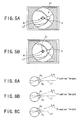
- the direction of the visual line of the eye E is leftward when seen from the examinee (see Figs. 8A to 8C ).
- the controller 80 controls to form and display the reticle mark LT for periphery photographing having the display shape extending leftward (see Figs. 7A to 7C ) with respect to the display shape of the reticle mark LT for standard photographing (see Figs. 5A and 5B ).
- the controller 80 controls to display the reticle mark LT for periphery photographing having the display shape which is made larger in a direction where the direction of the visual line of the eye E is guided than the display shape of the reticle mark LT for standard photographing.
- the optical axis L1 is brought to a state where the alignment thereof is performed with respect to the vicinity of a corneal vertex Ev of the eye E (see Fig. 8A ).
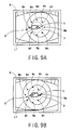
- the display is switched to the anterior-segment observation image from the fundus observation image in this state, the image shown in Fig. 9A is displayed.
- the fundus observation image with fewer flares caused by reflection from the cornea or a crystalline lens can be easily obtained since a deviation between the corneal vertex Ev and the optical axis L1 is small.
- the fundus illumination light is apt to be blocked by an iris of the eye E depending on a dilated state of the pupil of the eye E.
- the corneal vertex Ev in the preferred embodiment of the present invention indicates a point where a straight line which is parallel to the optical axis L1 and passes through the center of corneal curvature of the eye E intersects the cornea Ec.
- the optical axis L1 is brought to a state where the alignment thereof is performed with respect to the vicinity of a pupil center Pc of the eye E (see Fig. 8B )
- the display is switched to the anterior-segment observation image from the fundus observation image in this state, the image shown in Fig. 9B is displayed.
- the fundus illumination light is hardly blocked by the iris.
- the fundus observation image is apt to suffer flares since the deviation between the corneal vertex Ev and the optical axis L1 is large.
- the optical axis L1 is brought to a state where the alignment thereof is performed with respect to the vicinity of the midpoint between the corneal vertex Ev and the pupil center Pc (see Fig. 8C ).
- the fundus illumination light is hardly blocked by the iris compared with the case where the alignment of the optical axis L1 is performed with respect to the corneal vertex Ev.
- the fundus observation image is less apt to suffer flares compared with the case where the alignment of the optical axis L1 is performed with respect to the pupil center Pc.
- the photographing unit 3 When the photographing unit 3 is moved in the X- and Y-directions within a range where the alignment mark Al is positioned within the reticle mark LT, and a preferable fundus observation image with fewer flares and less unevenness in illumination becomes observable on the screen of the monitor 8, the photographing is performed through operation of the switch 4b (the focusing may be performed again before the photographing). Accordingly, a preferable fundus photographing image with fewer flares and less unevenness in illumination can be easily obtained. That is to say, the optical axis L1 (the photographing unit 3) can be guided to an alignment state where the preferable fundus photographing image can be easily obtained.
- the display shape of the reticle mark LT is varied in accordance with the presenting position of the fixation target in a fundus observation state (at the time of displaying the fundus observation image)
- the display shape of the reticle mark LT is varied in accordance with the presenting position of the fixation target in an anterior-segment observation state (at the time of displaying the anterior-segment observation image). This allows smooth periphery photographing of the fundus after the switching from the anterior-segment observation state to the fundus observation state.
- fixation target presenting system (fixation target presenting optical system) is provided in the photographing unit 3, it is also preferable that the fixation target presenting system is provided outside the photographing unit 3.
- fixation target presenting system a known system such as a system using a liquid crystal display and a system using a plurality of fixation target light sources (fixation lamps) can be used. It is essential only that the systems be arranged so that the display shape of the reticle mark LT is varied in accordance with the presenting position of the fixation target.
- the alignment mark is electrically formed and displayed in the position on the screen of the monitor corresponding to the center position of the plurality of the alignment target images formed by the alignment target projection optical system
- the picked-up alignment target image is displayed as it is with the fundus observation image and/or the anterior-segment observation image without forming and displaying the alignment mark, and the alignment in the X- and Y-directions is performed based on the displayed images and the reticle mark.
- the alignment target is projected onto the eye from the front, not in a slanting direction.
- the camera for picking up the anterior-segment observation image doubles as the alignment target image detection means (i.e., the anterior-segment observation optical system doubles as the alignment target image detection optical system)
- a dedicated photodetector that defines the alignment target image detection means (the alignment target image detection optical system) is provided.
- the camera (the image-pickup element) for picking up the fundus observation image and the camera (the image-pickup element) for picking up the anterior-segment observation image are separately provided, it is also preferable that the anterior-segment observation image is picked up by the camera (the image-pickup element) for picking up the fundus observation image. In other words, the camera (the image-pickup element) may be shared.
- the display shape of the reticle mark LT is not limited to the above-described display shape, and it is essential only that the display shape be arranged such that the optical axis L1 is guided within a predetermined region from the vicinity of the corneal vertex to the vicinity of the pupil center.
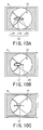
- the reticle mark LT may have a display shape including a mark LTK for positioning the optical axis L1 in the vicinity of the corneal vertex, a mark LTP for positioning the optical axis L1 in the vicinity of the pupil center, and a mark LTC which connects the mark LTK and the mark LTP.
- the reticle mark LT may have the display shape in which a region LTV for positioning the optical axis L1 in the vicinity of the corneal vertex is smaller than a region for positioning the optical axis L1 in the vicinity of the pupil center and other regions.
- the permissible range of the alignment is made smaller when the optical axis L1 is positioned in the vicinity of the corneal vertex where flares are hardly caused, so that a preferable fundus photographing image with fewer flares can be easily obtained.
- the reticle mark LT may have the display shape of a line, as shown in Fig. 10C .
- the reticle mark LT may be varied in size in accordance with the pupil diameter of the eye E which is obtained based on the image signal from the camera 65. For example, if the pupil diameter of the eye E is larger, the reticle mark LT is made larger, and if the pupil diameter of the eye E is smaller, the reticle mark LT is made smaller.
- the permissible range of the alignment for making the display switching from the anterior-segment observation image to the fundus observation image may be changed.
- the permissible range of the alignment may be made larger in the direction where the direction of the visual line of the eye E is guided than that at the time of standard photographing.
Landscapes
- Life Sciences & Earth Sciences (AREA)
- Health & Medical Sciences (AREA)
- Medical Informatics (AREA)
- Biophysics (AREA)
- Ophthalmology & Optometry (AREA)
- Engineering & Computer Science (AREA)
- Biomedical Technology (AREA)
- Heart & Thoracic Surgery (AREA)
- Physics & Mathematics (AREA)
- Molecular Biology (AREA)
- Surgery (AREA)
- Animal Behavior & Ethology (AREA)
- General Health & Medical Sciences (AREA)
- Public Health (AREA)
- Veterinary Medicine (AREA)
- Eye Examination Apparatus (AREA)
Abstract
Description
- The present invention relates to a fundus camera which photographs a fundus of an examinee's eye.
- There is known a fundus camera which changes a display position of a reticle mark that defines an alignment reference in accordance with a presenting position of a fixation target on which an examinee's eye is fixated (see Japanese Patent Application Unexamined Publication
Heill-4808 - However, in the photographing of the periphery of the fundus, it is not necessarily most appropriate to perform the alignment of the photographing optical axis with respect to the pupil center. This is because if, for example, the photographing optical axis is largely deviated from a corneal vertex in the photographing, a photographing image of the fundus is apt to suffer flares. Accordingly, the alignment reference position such that a preferable photographing image of the fundus can be obtained differs with a pupil diameter, a corneal shape or other factors of the eye.
- An object of the invention is to overcome the problems described above and to provide a fundus camera which is capable of preferably performing photographing of the periphery of a fundus of an examinee's eye irrespective of the state of the eye.
- To achieve the objects and in accordance with the purpose of the present invention, a fundus camera comprises a photographing optical system having a photographing optical axis, for photographing a fundus of an examinee's eye, a fundus observation optical system having an image-pickup element which picks up an observation image of the fundus of the eye, an alignment target projection optical system for projecting an alignment target onto an anterior segment of the eye, an alignment target image detection optical system having a photodetector which detects an image of the alignment target, a photographing unit which houses the photographing optical system, the fundus observation optical system, the alignment target projection optical system and the alignment target image detection optical system, a moving mechanism which moves the photographing unit in order to perform alignment of the photographing optical axis so as to have a predetermined positional relationship with the eye, a fixation target presenting system for presenting a fixation target for guiding a direction of a visual line of the eye, a presenting position of the fixation target being arranged to be selectable or changeable, a display unit, and a controller which controls the display unit to display the fundus observation image and the alignment target image on a screen of the display unit, wherein the controller includes a program for electrically forming and displaying a reticle mark that defines an alignment reference in a predetermined position on the screen at the time of displaying the fundus observation image while varying a display shape of the reticle mark in accordance with the presenting position of the fixation target.
- Additional objects and advantages of the invention are set forth in the description which follows, are obvious from the description, or may be learned by practicing the invention. The objects and advantages of the invention may be realized and attained by the fundus camera in the claims.
- The accompanying drawings, which are incorporated in and constitute a part of this specification, illustrate embodiments of the present invention and, together with the description, serve to explain the objects, advantages and principles of the invention. In the drawings,
-
Fig. 1 is a view showing a schematic configuration of a fundus camera according to a preferred embodiment of the present invention; -
Fig. 2 is a view showing a schematic configuration of an optical system and a control system of the fundus camera; -
Fig. 3 is a view illustrating presenting positions of a fixation target; -
Figs. 4A and 4B are views showing examples in displaying an observation image of an anterior segment of an examinee's eye; -
Figs. 5A and 5B are views showing examples in displaying an observation image of a fundus of the eye; -
Figs. 6A, 6B and 6C are views showing a display shape of a reticle mark varied in accordance with the presenting positions of the fixation target; -
Figs. 7A, 7B and 7C are views showing examples in displaying the fundus observation image at the time of photographing the periphery of the fundus such that a papilla of the right eye is arranged to be the center of the image; -
Figs. 8A, 8B and 8C are views showing a relationship between the eye of which a direction of a visual line is leftward and a photographing optical axis; -
Figs. 9A and 9B are views showing examples in displaying the anterior-segment observation image at the time of photographing the periphery of the fundus such that the papilla of the right eye is arranged to be the center of the image; and -
Figs. 10A, 10B and 10C are views showing modified examples of the display shape of the reticle mark. - A detailed description of a fundus camera according to preferred embodiments of the present invention is provided below with reference to the accompanying drawings.
Fig. 1 is a view showing a schematic configuration of a fundus camera according to a preferred embodiment of the present invention. - The fundus camera comprises a
base 1, amobile base 2 movable in a right/left direction (hereinafter referred to as an "X-direction") and a back/forth direction (hereinafter referred to as a "Z-direction") with reference to thebase 1 through tilting operation of ajoystick 4, a photographingunit 3 movable in the right/left direction, an up/down direction (hereinafter referred to as a "Y-direction"), and the back/forth direction with reference to themobile base 2 under control of acontroller 80 to be described later, and aface support unit 5 fixedly provided on thebase 1 for supporting a face (a head) of an examinee. Movingunits unit 3 is placed on the X table. The movingunit 7 moves the X and Z tables individually by a motor and other moving mechanisms so as to move the photographingunit 3 in the X-direction and/or the Y-direction. The movingunit 6 moves the Y table by a motor and other moving mechanisms so as to move the photographingunit 3 in the Y-direction. Besides, for the moving mechanisms as themoving units unit 3 is moved in the Y-direction also by driving of the movingunit 6 through rotational operation of a rotatingknob 4a of thejoystick 1. A monitor (a display) 8 which displays images including an observation image of an anterior segment of an examinee's eye, an observation image of a fundus of the eye, and a photographing image of the fundus is provided on the examiner's side of the photographingunit 3. -
Fig. 2 is a view showing a schematic configuration of an optical system and a control system housed in the photographingunit 3. The optical system comprises an illuminationoptical system 10, a fundus observation/photographingoptical system 30, an alignment target projectionoptical system 50, an anterior-segment observationoptical system 60 and a fixation target presentingoptical system 70. - The illumination
optical system 10 comprises an illumination optical system for fundus observation and an illumination optical system for photographing. Illumination light emitted from anillumination light source 11 for fundus observation such as a halogen light is made into infrared illumination light by aninfrared transmission filter 12 which transmits infrared light with a wavelength of less than about 900 nm, and is reflected by adichroic mirror 16 via acondenser lens 13. Thedichroic mirror 16 has a wavelength-selecting property of reflecting infrared light and transmitting visible light. The infrared illumination light reflected by thedichroic mirror 16 passes through aring slit plate 17, arelay lens 18, atotal reflection mirror 19, ablack dot plate 20 having a black dot at its center and arelay lens 21, and is reflected by anapertured mirror 22 and is projected onto a fundus Ef of an examinee's eye E via anobjective lens 25. Besides, an infrared light source such as an infrared light-emitting diode may be used instead of thelight source 11 such as the halogen light and theinfrared transmission filter 12. - Visible illumination light emitted from a visible
illumination light source 14 for photographing such as a flash light passes through acondenser lens 15 and is transmitted through thedichroic mirror 16 and is projected onto the fundus Ef via thering slit plate 17 to theobjective lens 25. - The fundus observation/photographing
optical system 30 comprises a fundus observationoptical system 30a and a photographingoptical system 30b. The infrared light and the visible light reflected from the fundus Ef pass through theobjective lens 25, anaperture 22a in theapertured mirror 22, a photographingdiaphragm 31 placed in the vicinity of theaperture 22a and a focusinglens 32 and enter animage forming lens 33. The photographingdiaphragm 31 is placed in a position substantially conjugate with a pupil of the eye E with reference to theobjective lens 25. The focusinglens 32 is placed so as to be movable by a movingunit 49 consisting of a moving mechanism such as a motor in a direction of an optical axis L1 of the fundus observation/photographing optical system 30 (the objective lens 25). A movabletotal reflection mirror 34 is placed so as to be insertable into/removable from an optical path of the fundus observation/photographingoptical system 30 by an inserting/removingunit 39 consisting of an inserting/removing mechanism such as a motor, and is removed from the optical path at the time of photographing. When themirror 34 is removed from the optical path, the visible reflection light is photo-received on a CCD camera (an image-pickup element) 35 for photographing having sensitivity to a visible range and forms an image of the fundus Ef (a fundus photographing image). Meanwhile, when themirror 34 is inserted into the optical path the infrared reflection light reflected by themirror 34 is reflected by adichroic mirror 37, is photo-received on a CCD camera (an image-pickup element) 38 for fundus observation having sensitivity to an infrared range via arelay lens 36 and forms an image of the fundus Ef (a fundus observation image). Thedichroic mirror 37 has a wavelength-selecting property of reflecting infrared light and transmitting visible light. - A movable
dichroic mirror 24 that defines an optical path dividing member is placed so as to be insertable into/removable from an optical path between theobjective lens 25 and the apertured mirror 22 (the photographing diaphragm 31) by an inserting/removingunit 66 consisting of an inserting/removing mechanism such as a motor, and is removed from the optical path at the time of photographing. Thedichroic mirror 24 has a wavelength-selecting property of reflecting infrared light with a wavelength of about 900 nm or more from an infraredillumination light source 58 for anterior-segment observation and the alignment target projectionoptical system 50 to be described later, and transmitting the infrared light with the wavelength of less than about 900 nmfrom the illumination optical system for fundus observation. - As shown in a figure S enclosed with dashed lines in
Fig. 2 , the alignment target projectionoptical system 50 comprises two first projection optical systems in a pair which have optical axes placed so as to be laterally symmetrical with respect to the optical axis L1, and six second projection optical systems in pairs which have optical axes placed so as to be laterally symmetrical with respect to the optical axis L1. Each of the two first projection optical systems includes an infraredlight source 51 such as an infrared light-emitting diode which emits the infrared light with the wavelength of about 900 nm or more and acollimating lens 52 and projects infrared target light at an infinite distance (projects an alignment target at an infinite distance) onto an anterior segment (a cornea Ec) of the eye E with substantially parallel light. Meanwhile, each of the six second projection optical systems includes an infraredlight source 53 such as an infrared light-emitting diode which emits the infrared light with the wavelength of about 900 nm or more, and projects infrared target light at a finite distance (projects an alignment target at a finite distance) onto the anterior segment (the cornea Ec) of the eye E with divergent light. Besides, in the preferred embodiment of the present invention, as shown in the figure S enclosed with the dashed lines inFig. 2 , the first projection optical systems and the second projection optical systems are placed at intervals of 45° each other on a concentric circle having the optical axis L1 as its center (e.g., a concentric circle of 3-mm radius). - Infrared illumination light emitted from the infrared
illumination light source 58 for anterior-segment observation such as an infrared light-emitting diode which emits the infrared light with the wavelength of about 900 nm or more is reflected by the anterior segment of the eye E and thedichroic mirror 24 inserted into the optical path, is photo-received on a CCD camera (an image-pickup element) 65 for anterior-segment observation having sensitivity to an infrared range via afield lens 61, atotal reflection mirror 62, adiaphragm 63 and arelay lens 64, and forms an image of the anterior segment of the eye E (an anterior-segment observation image). TheCCD camera 65 doubles as image-pickup means for alignment target image detection (i.e., the anterior-segment observationoptical system 60 doubles as an alignment target image detection optical system), and picks up the anterior-segment image formed by thelight source 58 and images of the alignment targets formed by the alignment target projectionoptical system 50. - Red fixation target light emitted from a fixation target light source (a fixation lamp) 74 such as a red light-emitting diode passes through an aperture in a shielding
plate 72 and arelay lens 75 and is transmitted through thedichroic mirror 37. The red fixation target light transmitted through thedichroic mirror 37 is reflected by thedichroic mirror 34 inserted into the optical path, passes through theimage forming lens 33 to theobjective lens 25, and is projected onto the fundus Ef (i.e., a fixation target is projected thereonto). The shieldingplate 72 hasapertures 71a to 71h, one of which is placed in such a position in front of thelight source 74 that is not on an optical axis L2 coaxial with the optical axis L1 by being rotated by amotor 73. As shown inFig. 3 , one of eight fixation target presenting positions is selected by selecting one of theapertures 71a to 71h. A fixation target presenting position 91L (a standard position in photographing the left eye) corresponding to theaperture 71a is selected when photographing the vicinity of a posterior pole area (a center port ion) of the fundus of the left eye which includes a macular spot and an optic papilla in a balanced manner so as to be the center of the image. Meanwhile, a fixation target presenting position 91R (a standard position in photographing the right eye) corresponding to theaperture 71b is selected when photographing the vicinity of a posterior pole area (a center portion) of the fundus of the right eye including a macular spot and an optic papilla in a balanced manner so as to be the center of the image. In addition, fixationtarget presenting positions 92 to 97 corresponding to theapertures 71c to 71h are selected when photographing peripheral areas (peripheral portions) of the fundus. - Image signals outputted from the
CCD cameras controller 80. Thecontroller 80 detects the alignment target images based on the image signal from theCCD camera 65 and obtains an alignment deviation amount of the optical axis L1 (the photographing unit 3) with respect to the eye E in the X- and Y-directions . In addition, thecontroller 80 is connected to themonitor 8 and performs a display control of themonitor 8. For example, both at the time of displaying the anterior-segment observation image by the CCD camera 65 (seeFigs. 4A and 4B ) and at the time of displaying the fundus observation image by the CCD camera 38 (seeFigs. 5A and 5B ), thecontroller 80 controls to electrically form and display a reticle mark LT that defines an alignment reference in a predetermined position on a screen of themonitor 8 while controlling to electrically form and display on the screen of themonitor 8 an alignment mark A1 of which a relative distance from the reticle mark LT varies in accordance with the alignment deviation amount in the X- and Y-directions obtained based on the image signal from theCCD camera 65. Thecontroller 80 is connected with the movingunits units rotation knob 4a, a photographingswitch 4b, aswitch unit 84 including various switches, amemory 85, the light sources, and other constituent elements (inFig. 2 , a part of connection lines are not shown). Theswitch unit 84 includes a focusingswitch 84a, a fixation target presentingposition changing switch 84b and other switches. - Operation of the fundus camera having the above-described configuration in the case of photographing the center portion of the fundus (hereinafter, referred to as standard photographing) and operation of the fundus camera having the above-described configuration in the case of photographing the peripheral portion of the fundus (hereinafter, referred to as periphery photographing) will be described separately. Provided below is a description in the case of photographing the right eye.
- A description in the case of the standard photographing is provided. First, the face of the examinee is supported by the
face support unit 5. In addition, the fixation target presenting position 91R shown inFig. 3 is selected through operation of theswitch 84b. In the initial stage, thedichroic mirror 24 has been already inserted into the optical path, and the anterior-segment observation image picked up by theCCD camera 65 is displayed (appears) on themonitor 8. Thecontroller 80 controls to electrically form and display in the center of the screen of themonitor 8 the reticle mark LT and a circular mark P indicating the minimum pupil diameter of photographing. The photographingunit 3 is moved in the X-direction and/or the Y-direction so that the anterior-segment observation image is placed in the center of the screen of themonitor 8. In addition, the photographingunit 3 is moved in the Z-direction so that the anterior-segment observation image is brought into focus. When the anterior-segment observation image comes to be placed in the vicinity of the center of the screen of themonitor 8, eight alignment target images Ma to Mh formed by the alignment target projectionoptical system 50 also come to be displayed (appear)(seeFig. 4A ). The reticle mark LT used for standard photographing is set to have a display shape and a display position so that the optical axis L1 is positioned in the vicinity of a corneal vertex of the eye E and the vicinity of a pupil center of the eye E (i.e., alignment of the optical axis L1 is performed) when the alignment mark A1 is positioned within (enters) the reticle mark LT. - When the alignment target images Ma to Mh are picked up by the
CCD camera 65, thecontroller 80 obtains the alignment deviation amount in the X- and Y-directions based on the image signal from theCCD camera 65. In the preferred embodiment of the present invention, thecontroller 80 detects a center position of the alignment target images Ma to Mh in the X- and Y-directions as a substantial corneal center, and calculates a difference (a deviation amount) between the center position and an alignment reference position in the X- and Y-directions previously set in the CCD camera 65 (e.g., an intersection point of an image-pickup surface of theCCD camera 65 and the optical axis L1). - When the center position of the alignment target images Ma to Mh is obtained, the
controller 80 controls to electrically form and display the alignment mark A1 in a position on themonitor 8 which corresponds to the center position. In addition, thecontroller 80 controls display of the alignment mark A1 so that the relative distance from the reticle mark LT displayed on themonitor 8 varies in accordance with the alignment deviation amount in the X- and Y-directions obtained based on the image signal from theCCD camera 65. Besides, a program for performing the display control of themonitor 8 based on relationships between the alignment deviation amounts in the X- and Y-directions and the relative distances of the alignment mark A1 from the reticle mark LT at the time of displaying the anterior-segment observation image and at the time of displaying the fundus observation image is previously stored in thememory 85, and thecontroller 80 performs the display control of themonitor 8 by using the program. - When the alignment deviation amount in the X- and Y-directions changes by the movement of the photographing
unit 3 with respect to the eye E in the X- and Y-directions, thecontroller 80 controls to change the relative distance of the alignment mark A1 from the reticle mark LT. That is to say, a display position (a formation position) of the alignment mark A1 with respect to the reticle mark L1 varies in accordance with the change in the alignment deviation amount in the X- and Y-directions. - The photographing
unit 3 is further moved in the X- and Y-directions so that the alignment mark A1 is displayed within the reticle mark LT (seeFig. 4B ), and the alignment of the optical axis L1 (the photographing unit 3) with respect to the eye E in the X- and Y-directions is performed. In addition, it is checked whether or not the pupil diameter of the eye E is bigger than the circular mark P indicating the minimum pupil diameter. - In addition, the
controller 80 compares an interval between the images of the infinite alignment targets with intervals between the images of the finite alignment targets, and obtains an alignment deviation amount of the photographingunit 3 with respect to the eye E in the Z-direction (seeUSP 5,463,430 corresponding to Japanese Patent Application Unexamined Publication No.Hei06-46999 controller 80 increases/decreases the number of indicators G based on the alignment deviation amount in the Z-direction which is obtained based on the image signal from theCCD camera 65. Then, the photographingunit 3 is moved in the Z-direction so that only one indicator G is displayed (seeFig. 4B ), and alignment of the photographingunit 3 with respect to the eye E in the Z-direction is performed. - The
controller 80 judges whether or not the alignment in the X- and Y-directions is performed appropriately by determining whether or not the alignment deviation amount in the X- and Y-directions stays within a predetermined range of alignment completion for a given period of time. In addition, thecontroller 80 judges whether or not the alignment in the Z-direction is performed appropriately by determining whether or not the alignment deviation amount in the Z-direction stays within a predetermined range of alignment completion for a given period of time. - When the alignment states in the X-, Y- and Z-directions satisfy predetermined conditions for alignment completion, the
controller 80 automatically switches the display on themonitor 8 from the anterior-segment observation image to the fundus observation image. Besides, instead of the automatic display switching being performed, a message for manual display switching may be informed (displayed). - At the time of displaying the fundus observation image, the
controller 80, similarly to the case of displaying the anterior-segment observation image, controls to electrically form and display the reticle mark LT in a predetermined position on the screen of themonitor 8 while controlling to electrically form and display on the screen of themonitor 8 the alignment mark A1 of which the relative distance from the reticle mark LT varies in accordance with the alignment deviation amount in the X- and Y-directions (seeFig. 5A ). - In addition, the
controller 80 controls the display position of the alignment mark A1 so that the relative distance from the reticle mark LT corresponding to the alignment deviation amount in the X- and Y-directions at the time of displaying the fundus observation image differs from that at the time of displaying the anterior-segment observation image. To be more specific, thecontroller 80 controls the display of the alignment mark A1 so that the relative distance from the reticle mark LT in accordance with the alignment deviation amount in the X- and Y-directions at the time of displaying the fundus observation image becomes longer (e.g., about four or five times) than that at the time of displaying the anterior-segment observation image. That is to say, thecontroller 80 controls the display of the alignment mark A1 so that a proportion of change in the relative distance from the reticle mark LT with respect to a proportion of change in the alignment deviation amount in the X- and Y-directions at the time of displaying the fundus observation image becomes larger than that at the time of displaying the anterior-segment observation image. - In addition, also in the Z-direction, the
controller 80 increases/decreases the number of indicators G based on the alignment deviation amount in the Z-direction similarly to the case of displaying the anterior-segment observation image. In this case, similarly to the case of the alignment in the X- and Y-directions, display of the indicators G (e.g., the number of the indicators G) varying in accordance with the alignment deviation amount in the Z-direction at the time of displaying the fundus observation image may differ from that at the time of displaying the anterior-segment observation image. The photographingunit 3 is moved in the X- and Y-directions so that the alignment mark A1 is displayed within the reticle mark LT (seeFig. 5B ) and the alignment of the optical axis L1 (the photographing unit 3) with respect to the eye E in the X- and Y-directions is performed. In addition, the photographingunit 3 is moved in the Z-direction so that only one indicator G is displayed (seeFig. 5B ), and the alignment of the photographingunit 3 with respect to the eye E in the Z-direction is performed. Besides, in a case where the alignment of the optical axis L1 with respect to the eye E deviates widely, the display on themonitor 8 is automatically switched from the fundus observation image to the anterior-segment observation image. Also at this time, a message for the manual display switching may be informed (displayed) instead of the automatic display switching being performed. - Next, focusing is performed through operation of the
switch 84a while the fundus observation image on themonitor 8 is observed. Thecontroller 80 drives the movingunit 49 and moves the focusinglens 32 based on an input signal by theswitch 84a. Then, when a desired area in the fundus Ef becomes preferably observable, photographing is performed through operation of theswitch 4b. Thecontroller 80 drives the inserting/removingunit 39 so as to remove themirror 34 from the optical path, drives the inserting/removingunit 66 so as to remove thedichroic mirror 24 from the optical path, and lights thelight source 14. The fundus photographing image picked up by theCCD camera 35 is stored in thememory 85 and displayed on themonitor 8. - A description in the case of the periphery photographing is provided. When the presenting position of the fixation target is changed from the position for standard photographing to the position for periphery photographing (when the position for periphery photographing is selected) through operation of the
switch 84b, thecontroller 80 varies a display shape of the reticle mark LT in accordance with the changed (selected) presenting position of the fixation target. In the periphery photographing, eccentricities of the corneal vertex and the pupil center of the eye E become larger with an amount (angle) of inclination in a direction of a visual line of the eye E. Thecontroller 80 varies the display shape of the reticle mark LT in accordance with the changed (selected) presenting position of the fixation target so that when the alignment mark Al is displayed within the reticle mark LT, the alignment of the optical axis L1 is performed so that the optical axis L1 falls within a predetermined region from the vicinity of the corneal vertex to the vicinity of the pupil center of the eye E (on a virtual line between the corneal vertex and the pupil center). In other words, when the reticle mark LT is used for periphery photographing, it is set to have a display shape such that when the alignment mark A1 is placed within the reticle mark LT, the optical axis L1 is placed within the predetermined region from the vicinity of the corneal vertex to the vicinity of the pupil center of the eye E. For example, when the fixationtarget presenting position 95 inFig. 3 is selected, the display shape of the reticle mark LT is varied to the one shown inFig. 6A . When the fixationtarget presenting position 92 inFig. 3 is selected, the display shape of the reticle mark LT is varied to the one shown inFig. 6B . When the fixationtarget presenting position 94 inFig. 3 is selected, the display shape of the reticle mark LT is varied to the one shown inFig. 6C . Besides, as the amount (angle) of the inclination in the direction of the visual line of the eye E becomes larger, an eccentricity of the reticle mark LT at the time of the periphery photographing becomes larger than that of the reticle mark LT at the time of the standard photographing. - Incidentally, a program for controlling the display of the
monitor 8 based on a relationship between the presenting position of the fixation target and the display shape of the reticle mark LT varied in accordance with the presenting position of the fixation target is previously stored in thememory 85, and thecontroller 80 controls the display of themonitor 8 by using the program. That is to say, the display shapes of the reticle mark LT in all the presenting positions are set based on a virtual line between a display position of the alignment mark A1 at the time when the alignment of the optical axis L1 is performed with respect to the vicinity of the corneal vertex and a display position of the alignment mark A1 at the time when the alignment of the optical axis L1 is performed with respect to the vicinity of the pupil center, and are stored in thememory 85. The reticle mark LT may have the display shape of a frame which surrounds the virtual line or a line which traces the virtual line. In the preferred embodiment of the present invention, the reticle mark LT is set to have the display shape of a frame so that a permissible range of the alignment covers up to the position of the optical axis L1 deviated by 0.5 mm from the virtual line. - The periphery photographing in a case where the fixation
target presenting position 95 inFig. 3 is selected (periphery photographing such that the optic papilla of the right eye is arranged to be the center of the image) is described. In this case, the direction of the visual line of the eye E is leftward when seen from the examinee (seeFigs. 8A to 8C ). Thecontroller 80 controls to form and display the reticle mark LT for periphery photographing having the display shape extending leftward (seeFigs. 7A to 7C ) with respect to the display shape of the reticle mark LT for standard photographing (seeFigs. 5A and 5B ). In other words, thecontroller 80 controls to display the reticle mark LT for periphery photographing having the display shape which is made larger in a direction where the direction of the visual line of the eye E is guided than the display shape of the reticle mark LT for standard photographing. - When the alignment mark A1 is positioned in the right part within the reticle mark LT (i.e., the position where the reticle mark LT is displayed at the time of the standard photographing) (see
Fig. 7A ), the optical axis L1 is brought to a state where the alignment thereof is performed with respect to the vicinity of a corneal vertex Ev of the eye E (seeFig. 8A ). When the display is switched to the anterior-segment observation image from the fundus observation image in this state, the image shown inFig. 9A is displayed. In such an alignment state, the fundus observation image with fewer flares caused by reflection from the cornea or a crystalline lens can be easily obtained since a deviation between the corneal vertex Ev and the optical axis L1 is small. However, the fundus illumination light is apt to be blocked by an iris of the eye E depending on a dilated state of the pupil of the eye E. Besides, the corneal vertex Ev in the preferred embodiment of the present invention indicates a point where a straight line which is parallel to the optical axis L1 and passes through the center of corneal curvature of the eye E intersects the cornea Ec. - When the alignment mark A1 is positioned in the left part within the reticle mark L1 (see
Fig. 7B ), the optical axis L1 is brought to a state where the alignment thereof is performed with respect to the vicinity of a pupil center Pc of the eye E (seeFig. 8B ) When the display is switched to the anterior-segment observation image from the fundus observation image in this state, the image shown inFig. 9B is displayed. In such an alignment state, the fundus illumination light is hardly blocked by the iris. However, the fundus observation image is apt to suffer flares since the deviation between the corneal vertex Ev and the optical axis L1 is large. - When the alignment mark A1 is positioned in the vicinity of the center within the reticle mark LT (see
Fig. 7C ), the optical axis L1 is brought to a state where the alignment thereof is performed with respect to the vicinity of the midpoint between the corneal vertex Ev and the pupil center Pc (seeFig. 8C ). In such an alignment state, the fundus illumination light is hardly blocked by the iris compared with the case where the alignment of the optical axis L1 is performed with respect to the corneal vertex Ev. In addition, the fundus observation image is less apt to suffer flares compared with the case where the alignment of the optical axis L1 is performed with respect to the pupil center Pc. - When the photographing
unit 3 is moved in the X- and Y-directions within a range where the alignment mark Al is positioned within the reticle mark LT, and a preferable fundus observation image with fewer flares and less unevenness in illumination becomes observable on the screen of themonitor 8, the photographing is performed through operation of theswitch 4b (the focusing may be performed again before the photographing). Accordingly, a preferable fundus photographing image with fewer flares and less unevenness in illumination can be easily obtained. That is to say, the optical axis L1 (the photographing unit 3) can be guided to an alignment state where the preferable fundus photographing image can be easily obtained. - In the above description, while the display shape of the reticle mark LT is varied in accordance with the presenting position of the fixation target in a fundus observation state (at the time of displaying the fundus observation image), it is also preferable that the display shape of the reticle mark LT is varied in accordance with the presenting position of the fixation target in an anterior-segment observation state (at the time of displaying the anterior-segment observation image). This allows smooth periphery photographing of the fundus after the switching from the anterior-segment observation state to the fundus observation state.
- In the above description, while the fixation target presenting system (fixation target presenting optical system) is provided in the photographing
unit 3, it is also preferable that the fixation target presenting system is provided outside the photographingunit 3. As the fixation target presenting system, a known system such as a system using a liquid crystal display and a system using a plurality of fixation target light sources (fixation lamps) can be used. It is essential only that the systems be arranged so that the display shape of the reticle mark LT is varied in accordance with the presenting position of the fixation target. - In the above description, while the alignment mark is electrically formed and displayed in the position on the screen of the monitor corresponding to the center position of the plurality of the alignment target images formed by the alignment target projection optical system, it is also preferable that the picked-up alignment target image is displayed as it is with the fundus observation image and/or the anterior-segment observation image without forming and displaying the alignment mark, and the alignment in the X- and Y-directions is performed based on the displayed images and the reticle mark. In addition, it is also preferable that the alignment target is projected onto the eye from the front, not in a slanting direction.
- In the above description, while the camera (the image-pickup element) for picking up the anterior-segment observation image doubles as the alignment target image detection means (i.e., the anterior-segment observation optical system doubles as the alignment target image detection optical system), it is also preferable that a dedicated photodetector that defines the alignment target image detection means (the alignment target image detection optical system) is provided.
- In the above description, while the camera (the image-pickup element) for picking up the fundus observation image and the camera (the image-pickup element) for picking up the anterior-segment observation image are separately provided, it is also preferable that the anterior-segment observation image is picked up by the camera (the image-pickup element) for picking up the fundus observation image. In other words, the camera (the image-pickup element) may be shared.
- The display shape of the reticle mark LT is not limited to the above-described display shape, and it is essential only that the display shape be arranged such that the optical axis L1 is guided within a predetermined region from the vicinity of the corneal vertex to the vicinity of the pupil center. For example, as shown in
Fig. 10A , the reticle mark LT may have a display shape including a mark LTK for positioning the optical axis L1 in the vicinity of the corneal vertex, a mark LTP for positioning the optical axis L1 in the vicinity of the pupil center, and a mark LTC which connects the mark LTK and the mark LTP. - In addition, as shown in
Fig. 10B , the reticle mark LT may have the display shape in which a region LTV for positioning the optical axis L1 in the vicinity of the corneal vertex is smaller than a region for positioning the optical axis L1 in the vicinity of the pupil center and other regions. By having such a display shape, the permissible range of the alignment is made larger when the optical axis L1 is positioned in the vicinity of the pupil center where flares are apt to be caused, so that a preferable fundus photographing image with fewer flares can be easily obtained. Meanwhile, the permissible range of the alignment is made smaller when the optical axis L1 is positioned in the vicinity of the corneal vertex where flares are hardly caused, so that a preferable fundus photographing image with fewer flares can be easily obtained. In addition, the reticle mark LT may have the display shape of a line, as shown inFig. 10C . - The reticle mark LT may be varied in size in accordance with the pupil diameter of the eye E which is obtained based on the image signal from the
camera 65. For example, if the pupil diameter of the eye E is larger, the reticle mark LT is made larger, and if the pupil diameter of the eye E is smaller, the reticle mark LT is made smaller. - Accompanied by variation of the display shape of the reticle mark LT, the permissible range of the alignment for making the display switching from the anterior-segment observation image to the fundus observation image may be changed. For example, at the time of periphery photographing, the permissible range of the alignment may be made larger in the direction where the direction of the visual line of the eye E is guided than that at the time of standard photographing.
- The foregoing description of the preferred embodiments of the invention has been presented for purposes of illustration and description. It is not intended to be exhaustive or to limit the invention to the precise form disclosed, and modifications and variations are possible in the light of the above teachings or may be acquired from practice of the invention. The embodiments chosen and described in order to explain the principles of the invention and its practical application to enable one skilled in the art to utilize the invention in various embodiments and with various modifications as are suited to the particular use contemplated. It is intended that the scope of the invention be defined by the claims appended hereto.
Claims (7)
- A fundus camera comprising:a photographing optical system (30b) having a photographing optical axis (L1), for photographing a fundus (Ef) of an examinee's eye (E);a fundus observation optical system (30a) having an image-pickup element (38) which picks up an observation image of the fundus of the eye;an alignment target projection optical system (50) for projecting an alignment target onto an anterior segment of the eye;an alignment target image detection optical system (60) having a photodetector (65) which detects an image of the alignment target;a photographing unit (3) which houses the photographing optical system, the fundus observation optical system, the alignment target projection optical system and the alignment target image detection optical system;a moving mechanism (6, 7) which moves the photographing unit in order to perform alignment of the photographing optical axis so as to have a predetermined positional relationship with the eye;a fixation target presenting system (70) for presenting a fixation target for guiding a direction of a visual line of the eye, a presenting position of the fixation target being arranged to be selectable or changeable;a display unit (8); anda controller (80) which controls the display unit to display the fundus observation image and the alignment target image on a screen of the display unit, whereinthe controller includes a program for electrically forming and displaying a reticle mark (LT) that defines an alignment reference in a predetermined position on the screen at the time of displaying the fundus observation image while varying a display shape of the reticle mark in accordance with the presenting position of the fixation target.
- The fundus camera according to claim 1, wherein
the presenting position of the fixation target is arranged to be selectable or changeable between a position for standard photographing such that a center portion of the fundus is photographed and a position for periphery photographing such that a peripheral portion of the fundus is photographed, and
the program is arranged to display a reticle mark for standard photographing in response to selection of or change to the position for standard photographing, and display a reticle mark for periphery photographing having a display shape which is made larger in a direction where the direction of the visual line of the eye E is guided than a display shape of the reticle mark for standard photographing in response to selection of or change to the position for periphery photographing. - The fundus camera according to claim 1, wherein
the presenting position of the fixation target is arranged to be selectable or changeable between a position for standard photographing such that a center portion of the fundus is photographed and a position for periphery photographing such that a peripheral portion of the fundus is photographed, and
the program is arranged to vary the display shape of the reticle mark so that the photographing optical axis is positioned within a predetermined region from the vicinity of a corneal vertex to the vicinity of a pupil center when the alignment target image is positioned within the reticle mark in response to selection of or change to the position for periphery photographing. - The fundus camera according to claim 1, wherein
the presenting position of the fixation target is arranged to be selectable or changeable between a position for standard photographing such that a center portion of the fundus is photographed and a position for periphery photographing such that a peripheral portion of the fundus is photographed, and
the program is arranged to vary the display shape of the reticle mark based on a virtual line between a display position of the alignment target image at the time when the alignment of the photographing optical axis is performed with respect to the vicinity of a corneal vertex and a display position of the alignment target image at the time when the alignment of the photographing optical axis is performed with respect to the vicinity of a pupil center in response to selection of or change to the position for periphery photographing. - The fundus camera according to claim 4, wherein the program is arranged to vary the reticle mark to have the display shape of one of a frame which surrounds the virtual line and a line which traces the virtual line.
- The fundus camera according to claim 1, wherein the program is arranged to electrically form and display an alignment mark (A1), instead of the alignment target image, of which a relative distance from the reticle mark varies in accordance with an alignment deviation amount of the photographing optical axis with respect to the eye which is obtained based on an output signal from the photodetector.
- The fundus camera according to claim 1, further comprising:an anterior-segment observation optical system (65) having an image-pickup element which picks up an observation image of the anterior segment of the eye, whereinthe controller controls the display unit to display the anterior-segment observation image and the alignment target image on the screen of the display unit, andthe program is arranged to electrically form and display the reticle mark in the predetermined position on the screen at the time of displaying the anterior-segment observation image while varying the display shape of the reticle mark in accordance with the presenting position of the fixation target.
Applications Claiming Priority (1)
| Application Number | Priority Date | Filing Date | Title |
|---|---|---|---|
| JP2007052101A JP4937792B2 (en) | 2007-03-01 | 2007-03-01 | Fundus camera |
Publications (1)
| Publication Number | Publication Date |
|---|---|
| EP1972266A1 true EP1972266A1 (en) | 2008-09-24 |
Family
ID=39564732
Family Applications (1)
| Application Number | Title | Priority Date | Filing Date |
|---|---|---|---|
| EP08152140A Withdrawn EP1972266A1 (en) | 2007-03-01 | 2008-02-29 | Fundus camera |
Country Status (3)
| Country | Link |
|---|---|
| US (1) | US7651223B2 (en) |
| EP (1) | EP1972266A1 (en) |
| JP (1) | JP4937792B2 (en) |
Cited By (2)
| Publication number | Priority date | Publication date | Assignee | Title |
|---|---|---|---|---|
| EP2394569A1 (en) * | 2010-06-10 | 2011-12-14 | Nidek Co., Ltd | Ophthalmic apparatus |
| US9532708B2 (en) | 2010-09-17 | 2017-01-03 | Alcon Lensx, Inc. | Electronically controlled fixation light for ophthalmic imaging systems |
Families Citing this family (21)
| Publication number | Priority date | Publication date | Assignee | Title |
|---|---|---|---|---|
| JP5371638B2 (en) * | 2009-09-01 | 2013-12-18 | キヤノン株式会社 | Ophthalmic imaging apparatus and method |
| WO2011047214A2 (en) * | 2009-10-14 | 2011-04-21 | Optimum Technologies, Inc. | Portable retinal camera and image acquisition method |
| JP5643000B2 (en) * | 2010-05-28 | 2014-12-17 | 株式会社ニデック | Ophthalmic equipment |
| JP5772117B2 (en) * | 2011-03-22 | 2015-09-02 | 株式会社ニデック | Fundus photographing device |
| US9039176B2 (en) * | 2011-03-31 | 2015-05-26 | Nidek Co., Ltd. | Corneal endothelial cell photographing apparatus |
| JP5864550B2 (en) * | 2011-04-22 | 2016-02-17 | 興和株式会社 | Ophthalmic measuring device |
| TWI468148B (en) * | 2012-03-23 | 2015-01-11 | Crystalvue Medical Corp | Auxiliary gaze and imaging focusing device |
| JP5776609B2 (en) * | 2012-03-30 | 2015-09-09 | 株式会社ニデック | Corneal endothelial cell imaging device |
| JP2014083397A (en) * | 2012-10-26 | 2014-05-12 | Canon Inc | Ophthalmologic apparatus, control method thereof, and program |
| JP2014090823A (en) * | 2012-11-01 | 2014-05-19 | Canon Inc | Ophthalmic imaging apparatus, imaging control device, and imaging control method |
| JP2014090822A (en) * | 2012-11-01 | 2014-05-19 | Canon Inc | Ophthalmic imaging apparatus, imaging control device, and imaging control method |
| US10149615B2 (en) | 2012-11-30 | 2018-12-11 | Kabushiki Kaisha Topcon | Fundus imaging apparatus that determines a state of alignment |
| CN103431839B (en) * | 2013-08-01 | 2015-11-18 | 深圳典邦科技有限公司 | A kind of fundus camera |
| IL239417A0 (en) * | 2015-06-15 | 2015-11-30 | Joshua Ben Nun | Ophthalmic ultrasound bio-microscope (ubm) apparatus |
| US10849498B2 (en) * | 2015-08-12 | 2020-12-01 | Carl Zeiss Meditec, Inc. | Alignment improvements for ophthalmic diagnostic systems |
| WO2019030375A2 (en) * | 2017-08-11 | 2019-02-14 | Carl Zeiss Meditec, Inc. | Systems and methods for improved ophthalmic imaging |
| CN115281605B (en) * | 2017-10-30 | 2025-06-03 | 威里利生命科学有限责任公司 | Fundus camera and method of operating a fundus camera |
| CN108542346B (en) * | 2018-02-02 | 2021-01-01 | 中国科学院上海光学精密机械研究所 | An automatic retinoscopy optometry optical system |
| WO2020104827A1 (en) * | 2018-11-20 | 2020-05-28 | Essilor International | Device and method for placing a phoropter head in a horizontal position |
| CN116616696B (en) * | 2022-02-14 | 2025-12-30 | 北京鹰瞳科技发展股份有限公司 | A three-coordinate support platform for a fundus camera and a fundus camera |
| CN114587269B (en) * | 2022-02-21 | 2025-02-28 | 中国人民解放军联勤保障部队第九〇〇医院 | A system, device and method for realizing mobile phone to take photos and check the anterior and posterior segments of the eye |
Citations (6)
| Publication number | Priority date | Publication date | Assignee | Title |
|---|---|---|---|---|
| JPH0646999A (en) | 1992-07-31 | 1994-02-22 | Nidek Co Ltd | Alignment detector |
| US5463430A (en) | 1992-07-31 | 1995-10-31 | Nidek Co., Ltd. | Examination apparatus for examining an object having a spheroidal reflective surface |
| WO2000030528A1 (en) * | 1998-11-23 | 2000-06-02 | Schepens Eye Research Institute, Inc. | Electro-optic binocular indirect ophthalmoscope |
| EP1452128A1 (en) * | 2003-02-28 | 2004-09-01 | Nidek Co., Ltd. | Fundus camera |
| EP1535566A1 (en) * | 2003-11-28 | 2005-06-01 | Nidek Co., Ltd. | Fundus Camera |
| WO2006106977A1 (en) * | 2005-03-31 | 2006-10-12 | Kabushiki Kaisha Topcon | Ophthalmologic imager |
Family Cites Families (11)
| Publication number | Priority date | Publication date | Assignee | Title |
|---|---|---|---|---|
| US4712894A (en) * | 1980-09-24 | 1987-12-15 | Tokyo Kogaku Kikai Kabushiki Kaisha | Ophthalmoscopic instrument having working position detecting means |
| JP3888771B2 (en) * | 1997-04-24 | 2007-03-07 | 株式会社トプコン | Fundus camera |
| JP3664937B2 (en) * | 2000-03-27 | 2005-06-29 | 株式会社ニデック | Ophthalmic equipment |
| JP3784247B2 (en) * | 2000-08-31 | 2006-06-07 | 株式会社ニデック | Fundus camera |
| JP3709335B2 (en) * | 2000-09-28 | 2005-10-26 | 株式会社ニデック | Ophthalmic equipment |
| JP3929721B2 (en) * | 2001-05-25 | 2007-06-13 | 株式会社ニデック | Fundus camera |
| JP4126244B2 (en) | 2003-03-27 | 2008-07-30 | 株式会社ニデック | Fundus camera |
| JP4047255B2 (en) * | 2003-09-25 | 2008-02-13 | 株式会社ニデック | Fundus camera |
| JP4774304B2 (en) | 2006-01-31 | 2011-09-14 | 株式会社ニデック | Fundus camera |
| WO2007114426A1 (en) * | 2006-03-31 | 2007-10-11 | Nidek Co., Ltd. | Ophthalmologic instrument |
| JP4886389B2 (en) * | 2006-06-29 | 2012-02-29 | 株式会社ニデック | Fundus camera |
-
2007
- 2007-03-01 JP JP2007052101A patent/JP4937792B2/en not_active Expired - Fee Related
-
2008
- 2008-02-29 EP EP08152140A patent/EP1972266A1/en not_active Withdrawn
- 2008-02-29 US US12/073,117 patent/US7651223B2/en not_active Expired - Fee Related
Patent Citations (7)
| Publication number | Priority date | Publication date | Assignee | Title |
|---|---|---|---|---|
| JPH0646999A (en) | 1992-07-31 | 1994-02-22 | Nidek Co Ltd | Alignment detector |
| US5463430A (en) | 1992-07-31 | 1995-10-31 | Nidek Co., Ltd. | Examination apparatus for examining an object having a spheroidal reflective surface |
| WO2000030528A1 (en) * | 1998-11-23 | 2000-06-02 | Schepens Eye Research Institute, Inc. | Electro-optic binocular indirect ophthalmoscope |
| EP1452128A1 (en) * | 2003-02-28 | 2004-09-01 | Nidek Co., Ltd. | Fundus camera |
| EP1535566A1 (en) * | 2003-11-28 | 2005-06-01 | Nidek Co., Ltd. | Fundus Camera |
| WO2006106977A1 (en) * | 2005-03-31 | 2006-10-12 | Kabushiki Kaisha Topcon | Ophthalmologic imager |
| EP1864609A1 (en) * | 2005-03-31 | 2007-12-12 | Kabushiki Kaisha TOPCON | Ophthalmologic imager |
Cited By (4)
| Publication number | Priority date | Publication date | Assignee | Title |
|---|---|---|---|---|
| EP2394569A1 (en) * | 2010-06-10 | 2011-12-14 | Nidek Co., Ltd | Ophthalmic apparatus |
| US8857987B2 (en) | 2010-06-10 | 2014-10-14 | Nidek Co., Ltd. | Ophthalmic apparatus |
| US9532708B2 (en) | 2010-09-17 | 2017-01-03 | Alcon Lensx, Inc. | Electronically controlled fixation light for ophthalmic imaging systems |
| EP2618721B1 (en) * | 2010-09-17 | 2019-05-29 | Alcon LenSx, Inc. | Electronically controlled fixation light for ophthalmic imaging systems |
Also Published As
| Publication number | Publication date |
|---|---|
| JP2008212308A (en) | 2008-09-18 |
| US20080212029A1 (en) | 2008-09-04 |
| US7651223B2 (en) | 2010-01-26 |
| JP4937792B2 (en) | 2012-05-23 |
Similar Documents
| Publication | Publication Date | Title |
|---|---|---|
| US7651223B2 (en) | Fundus camera | |
| US7641340B2 (en) | Fundus camera | |
| EP2679148B1 (en) | Fundus photographing apparatus | |
| US7364295B2 (en) | Fundus camera | |
| EP1452128B1 (en) | Fundus camera | |
| US20090244483A1 (en) | Fundus camera | |
| EP2057938A1 (en) | Fundus camera | |
| JP5772117B2 (en) | Fundus photographing device | |
| JP4359489B2 (en) | Fundus camera | |
| EP1535566B1 (en) | Fundus Camera | |
| JP5554610B2 (en) | Fundus photographing device | |
| US7354153B2 (en) | Fundus camera | |
| JP5545982B2 (en) | Fundus camera | |
| JP5745864B2 (en) | Fundus photographing device | |
| JP5328517B2 (en) | Fundus photographing device | |
| JP4886388B2 (en) | Fundus camera | |
| JP4886387B2 (en) | Fundus camera | |
| JP4886389B2 (en) | Fundus camera | |
| JP5522629B2 (en) | Fundus photographing device | |
| JP5317049B2 (en) | Fundus camera | |
| JPH1043137A (en) | Ophthalmologic device | |
| JP5199008B2 (en) | Fundus camera | |
| JP2024110485A (en) | Eye refractive power measuring device and attachment for the eye refractive power measuring device | |
| JP2010035727A (en) | Fundus camera | |
| JP2010035729A (en) | Fundus camera |
Legal Events
| Date | Code | Title | Description |
|---|---|---|---|
| PUAI | Public reference made under article 153(3) epc to a published international application that has entered the european phase |
Free format text: ORIGINAL CODE: 0009012 |
|
| AK | Designated contracting states |
Kind code of ref document: A1 Designated state(s): AT BE BG CH CY CZ DE DK EE ES FI FR GB GR HR HU IE IS IT LI LT LU LV MC MT NL NO PL PT RO SE SI SK TR |
|
| AX | Request for extension of the european patent |
Extension state: AL BA MK RS |
|
| RIN1 | Information on inventor provided before grant (corrected) |
Inventor name: ICHIKAWA, NAOKI |
|
| 17P | Request for examination filed |
Effective date: 20090324 |
|
| AKX | Designation fees paid |
Designated state(s): DE FR GB |
|
| 17Q | First examination report despatched |
Effective date: 20100817 |
|
| GRAP | Despatch of communication of intention to grant a patent |
Free format text: ORIGINAL CODE: EPIDOSNIGR1 |
|
| INTG | Intention to grant announced |
Effective date: 20160129 |
|
| STAA | Information on the status of an ep patent application or granted ep patent |
Free format text: STATUS: THE APPLICATION IS DEEMED TO BE WITHDRAWN |
|
| 18D | Application deemed to be withdrawn |
Effective date: 20160609 |