EP1972255A1 - Capsule type medical device guiding system and its control method - Google Patents
Capsule type medical device guiding system and its control method Download PDFInfo
- Publication number
- EP1972255A1 EP1972255A1 EP06843530A EP06843530A EP1972255A1 EP 1972255 A1 EP1972255 A1 EP 1972255A1 EP 06843530 A EP06843530 A EP 06843530A EP 06843530 A EP06843530 A EP 06843530A EP 1972255 A1 EP1972255 A1 EP 1972255A1
- Authority
- EP
- European Patent Office
- Prior art keywords
- medical device
- magnetic field
- encapsulated medical
- capsule endoscope
- dynamic torque
- Prior art date
- Legal status (The legal status is an assumption and is not a legal conclusion. Google has not performed a legal analysis and makes no representation as to the accuracy of the status listed.)
- Granted
Links
Images




Classifications
-
- A—HUMAN NECESSITIES
- A61—MEDICAL OR VETERINARY SCIENCE; HYGIENE
- A61B—DIAGNOSIS; SURGERY; IDENTIFICATION
- A61B1/00—Instruments for performing medical examinations of the interior of cavities or tubes of the body by visual or photographical inspection, e.g. endoscopes; Illuminating arrangements therefor
- A61B1/04—Instruments for performing medical examinations of the interior of cavities or tubes of the body by visual or photographical inspection, e.g. endoscopes; Illuminating arrangements therefor combined with photographic or television appliances
- A61B1/041—Capsule endoscopes for imaging
-
- A—HUMAN NECESSITIES
- A61—MEDICAL OR VETERINARY SCIENCE; HYGIENE
- A61B—DIAGNOSIS; SURGERY; IDENTIFICATION
- A61B1/00—Instruments for performing medical examinations of the interior of cavities or tubes of the body by visual or photographical inspection, e.g. endoscopes; Illuminating arrangements therefor
- A61B1/00147—Holding or positioning arrangements
- A61B1/00158—Holding or positioning arrangements using magnetic field
-
- A—HUMAN NECESSITIES
- A61—MEDICAL OR VETERINARY SCIENCE; HYGIENE
- A61B—DIAGNOSIS; SURGERY; IDENTIFICATION
- A61B34/00—Computer-aided surgery; Manipulators or robots specially adapted for use in surgery
- A61B34/70—Manipulators specially adapted for use in surgery
-
- A—HUMAN NECESSITIES
- A61—MEDICAL OR VETERINARY SCIENCE; HYGIENE
- A61B—DIAGNOSIS; SURGERY; IDENTIFICATION
- A61B34/00—Computer-aided surgery; Manipulators or robots specially adapted for use in surgery
- A61B34/70—Manipulators specially adapted for use in surgery
- A61B34/73—Manipulators for magnetic surgery
Definitions
- the present invention relates to a guidance system for an encapsulated medical device inserted into an intracavital for obtaining internal biological information, and a method of controlling the same.
- a medical device guidance system configured to be magnetically guided has been proposed as disclosed in Jpn. Pat. Appln. KOKAI Publication No. 2004-255174 .
- a medical device guidance system is inserted in a intracavital, a capsule unit provided with spiral projections around the perimeter contains a magnet magnetized in the direction perpendicular to the longitudinal direction, and the advancing direction of the capsule unit can be smoothly changed by a magnetic field generated by a magnetic field control unit and a rotational magnetic field generator based on operating instructions.
- the direction of the capsule unit can be changed upon imaging, and an image of a desired part of the intracavital can be acquired.
- Jpn. Pat. Appln. KOKAI Publication No. 2003-111720 proposes an apparatus, which images an inspection area in the body of a patient by generating a 3D gradient magnetic field for determining the positions of a carrier, which contains a linear magnet and a measuring instrument or a sample collecting device, and functions as a robot to move freely in the body of a patient, by moving it in the body under remote control.
- a first encapsulated medical device guidance system has an internal biological information acquisition unit to acquire internal biological information; a communication unit to output the acquired internal biological information to the outside as an output signal; an encapsulated medical device having a magnet; a magnetic field generator which acts on the magnet, and generates a magnetic field for controlling at least one of the position and posture of the encapsulated medical device; and a control unit to control the magnetic field generator, wherein the control unit has a dynamic torque estimation unit to estimate a dynamic torque to be applied to the encapsulated medical device in a target posture, and controls a magnetic field generated from the magnetic field generator so that a magnetic torque generated by applying a magnetic field generated by the magnetic field generator to the magnet becomes substantially proportional to a dynamic torque estimated by the dynamic torque estimation unit.
- a second encapsulated medical device guidance system comprises an internal biological information acquisition unit to acquire internal biological information; a communication unit to output the acquired internal biological information to the outside as an output signal; an encapsulated medical device having a magnet; a magnetic field generator which acts on the magnet, and generates a magnetic field for controlling at least one of the position and posture of the encapsulated medical device; and a control unit to control the magnetic field generator, wherein the control unit controls the magnetic field generator which generates a magnetic field in a direction different from a desired direction of the encapsulated medical device generated by acting on a magnet, and controls the encapsulated medical device to face a desired direction, without being influenced by gravity.
- a method of guiding an encapsulated medical device comprising a step of setting a target posture of an encapsulated medical device, a step of determining a dynamic torque to be applied to the encapsulated medical device, a step of calculating a magnetic field for generating a magnetic torque proportional to the dynamic torque, in a target posture of the encapsulated medical device, and a step of generating the calculated magnetic field in the vicinity of the encapsulated medical device.
- FIG. 1 An explanation will be given on an encapsulated medical device guidance system according to one embodiment of the invention shown in FIG. 1 .
- This encapsulated medical device guidance system is largely divided into an encapsulated medical device 21 shown in FIGS. 2 to 6 , and a magnetic guidance unit 1 which generates a magnetic field for guiding a capsule endoscope.
- a capsule endoscope 21 is taken and explained as an example.
- the magnetic guidance unit 1 mainly comprises a guidance coil group (X1, X2, Y1, Y2, Z1, Z2, D1, D2, D3, D4, D5, D6, D7, D8), a power supply 2 for guidance coils, a guidance control unit 3, a controller 4, a sense coil unit 5 (5a - 5i), a position detector 6, a receiving antenna unit 7 (7a, 7b, 7c), an antenna selector 8, a receiving unit 9, a display unit 10, a drive coil 11, and a drive coil driver 12.
- a guidance coil group X1, X2, Y1, Y2, Z1, Z2, D1, D2, D3, D4, D5, D6, D7, D8
- a power supply 2 for guidance coils
- a guidance control unit 3 mainly comprises a guidance control unit 3, a controller 4, a sense coil unit 5 (5a - 5i), a position detector 6, a receiving antenna unit 7 (7a, 7b, 7c), an antenna selector 8, a receiving unit 9, a display unit 10, a drive coil 11, and
- Each of fourteen guidance coils X1, X2, Y1, Y2, Z1, Z2 and D1 - D8 has an air-core electromagnet, and forms an induction magnetic field generator.
- the guidance coils are arranged on each side of a rectangular parallelepiped.
- the direction of moving the capsule endoscope 21 forward and backward is assumed to be an X-axis direction
- the direction horizontally perpendicular to the X-axis is assumed to be a Y-axis direction
- a vertical (gravity) direction vertically perpendicular to the X-axis is assumed be a Z-axis direction.
- the guidance coils X1 and X2 are placed oppositely around the surfaces of front and rear sides, forming magnetic lines of force in the X-axis direction, and becoming vertical to the X-axis direction.
- the guidance coil X1 side is assumed to be front, and the guidance coil X2 side is assumed to be rear. Moving from the guidance coil X2 to the guidance coil X1 is assumed to be moving forward, and moving in the reverse direction is assumed to be moving backward.
- the guidance coils Y1 and Y2 are placed oppositely around the surfaces of both sides, forming magnetic lines of force in the Y-axis direction, and becoming vertical to the Y-axis direction.
- two guidance coils D3 and D7 are arranged within the guidance coil Y1 so as to divide the plane into two parts
- two guidance coils D1 and D5 are arranged within the guidance coil Y2 so as to divide the plane into two parts.
- the guidance coils Z1 and Z2 are placed oppositely around the top and bottom planes with respect to the Z-axis direction, forming magnetic lines of force in the Z-axis direction.
- two guidance coils D4 and D8 are arranged within the guidance coil Z1 so as to divide the plane into two parts
- two guidance coils D2 and D6 are arranged within the guidance coil Z2 so as to divide the plane into two parts.
- the guidance coil Z1 side is assumed to be top, and the guidance coil Z2 side is assumed to be bottom. Moving from the guidance coil Z2 to the guidance coil Z1 is assumed to be moving upward, and moving in the reverse direction is assumed to be moving downward.
- An alternating magnetic field formed by the drive coil 11 acts on the magnetic induction coil 31 and generates an induction current, and a magnetic field is generated from the magnetic induction coil.
- This alternating magnetic field includes one or more frequency components close to a resonance frequency generated by a coil (magnetic induction coil 31) and capacitor 33 described later provided in the capsule endoscope 21.
- the generated induction magnetic field is detected by the sense coils 5a - 5i, a signal including the position information is generated, and the signal is sent to the position detector 6. Based on this signal, the position detector calculates the position and posture information in the capsule endoscope 21. The position and posture information is sent to the guidance control unit 3, and used for calculation of a magnetic field to be generated by the guidance coil group.
- the group of guidance coils X1, X2, Y1, Y2, Z1, Z2, and D1 - D8 is a first magnetic gradient generating means, which generates a magnetic gradient (a first magnetic gradient) to be applied to the magnet in the capsule endoscope 21, and pulls the endoscope in a desired direction by moving in the longitudinal, horizontal and vertical directions.
- the guidance coil Z1 eliminates the influence of gravity when pulling the capsule endoscope 21 in a desired direction by moving up the endoscope by the above-mentioned guidance coil group, by generating a magnetic gradient (a second magnetic gradient) to be applied to the magnet in the capsule endoscope 21 to cancel the force of moving down the endoscope moved by the gravity.
- the guidance coils D4 and D8 can also generate the same force as the guidance coil Z1.
- the guidance coil Z1 is a second magnetic gradient generating means to eliminate the influence of gravity when moving the endoscope in a desired direction.
- the guidance coil Z2 eliminates the influence of buoyancy when pulling the capsule endoscope 21 in a desired direction by moving down the endoscope by the above-mentioned guidance coil group, by generating a magnetic field to be applied to the magnet in the capsule endoscope 21 to cancel the force of moving up the endoscope moved by the buoyancy.
- the guidance coils D2 and D6 can also generate the same force as the guidance coil Z1.
- the oppositely placed guidance coils X1 and X2, Y1 and Y2, and Z1 and Z2 generate a uniform magnetic field within the space surrounded by these guidance coils when a magnetic field is generated in the same direction, and forms an oblique magnetic field when a magnetic field is generated in the opposite direction.
- the coils D1 - D8 can form a highly uniform magnetic field or a gradient magnetic field by driving appropriately. Therefore, by controlling these fourteen guidance coils, it is possible to generate a magnetic field having desired intensity and gradient within a desired space.
- the guidance coil group in addition to moving the capsule endoscope 21 in the longitudinal, horizontal and vertical directions, it is possible to incline the endoscope to a position rising to the front, for example, by generating a magnetic field to tilt the distal end side up and proximal end side down, by combining the guidance coils X1, X2, Y1, Y2, Z1, Z2 and D1 - D8.
- These guidance coils are connected to the power supply 2 for guidance coils driven individually.
- the power supply 2 for guidance coils is controlled by the instruction from the guidance control unit 3, appropriately supplies power to a guidance coil necessary for generating a magnetic field, and generates a desired magnetic field in a desired space.
- Nine sense amplifiers 5a - 5i constituting the sense coil group 5 are arranged to be parallel to the side provided with the guidance coil Y1 and uniform in a plane, so that the correct position and posture of the capsule endoscope 21 can be obtained.
- the position related to the Z-axis is detected by providing a pair of oppositely placed sense coil set 5 and a drive coil 11.
- the position detector 6 receives an instruction to specify a timing of detecting the information about a position from the guidance control unit 3, and drives the drive coil driver 12 based on the instruction.
- the drive coil driver 12 generates a magnetic field by supplying an AC current to the drive coil 11, and generates an induction magnetic field in the capsule endoscope 21 in the magnetic field.
- Each sense coil of the sense coil group 5 detects a signal based on the induction magnetic field generated from the capsule endoscope 21, and outputs it to the position detector 6.
- the position detector 6 generates the position and posture information of the capsule endoscope 21 from the signal based on the induction magnetic field, and outputs it to the guidance control unit 3.
- the guidance control unit 3 determines a desired moving direction considering the position and posture information of the capsule endoscope 21 from the position detector 6, and instructs the power supply 2 for guidance coils to generate a magnetic field suitable for moving in the desired moving direction.
- the power supply 2 for guidance coils feeds a current to the guidance coils X1, X2, Y1, Y2, Z1, Z2 and D1 - D8 according to the instruction from the guidance control unit 3. Therefore, a magnetic field suitable for that moving is generated by the guidance coils, and the capsule endoscope 21 can be smoothly guided.
- the controller 4 is an input unit, which instructs the advancing direction and inclination of the capsule endoscope 21, by the operation of an input device by the operator, for example, tilting a joystick to a desired direction.
- an input device for example, tilting a joystick to a desired direction.
- buttons arranged to instruct all directions, a touch panel, or a line-of-sight input unit is available as a means to operate the controller 4.
- the guidance control unit 3 receives an instruction signal from the controller 4, position and posture information from the position detector 6, and signals related to the driving states of the guidance coils from the receiving unit 9, calculates a magnetic force (a magnetic field) for moving the capsule endoscope 21 to a desired position, determines magnetic forces generated by the guidance coils X1, X2, Y1, Y2, Z1, Z2 and D1 - D8 for generating the magnetic force, and sends an instruction to the power supply for each guidance coil.
- a magnetic force a magnetic field
- the guidance control unit 3 stops generation of a magnetic field during a communication period over which the image data acquired by the capsule endoscope 21 is sent to the receiving unit 9.
- the position detector 6 drives the drive coil 11 based on the instruction from the guidance control unit, and acquires the position information from the sense coil group 5.
- Three receiving antennas 7 are connected to the receiving unit through an antenna selector 8 for selecting the antennas.
- These receiving antennas 7 consist of a receiving antenna 7a (AX) for receiving communication data (internal biological information including image data) from the X-axis direction, a receiving antenna 7b (AY) for receiving internal biological information from the Y-axis direction, and a receiving antenna 7c (AZ) for receiving internal biological information from the Z-axis direction.
- the receiving antennas 7 can detect internal biological information in three axial directions.
- the antenna selector 8 selects the antennas 7a, 7b and 7c to be used for communication.
- the antenna selector 8 receives the intensity, direction and gradient of a magnetic field generated by the guidance coil group at the position of each antenna, identifies a receiving antenna influenced minimum by the magnetic field, and selects that receiving antenna. By selecting such a receiving antenna 7, the communication between the receiving unit 9 and capsule endoscope 21 can be stabilized.
- the receiving unit 9 sends the guidance control unit 3 the timing of receiving internal biological information from the capsule endoscope 21.
- the guidance control unit 3 stops generation of an induction magnetic field by the guidance coil set and drive coil 11, during the communication period for sending internal biological information (image data). Due to this stoppage, the receiving unit can receive the internal biological information from the capsule endoscope 21 without being influenced by an induction magnetic field.
- the communication period does not overlap the moving operation and position detection period, and it is possible to eliminate a noise in the internal biological information caused by an induction magnetic field, or an influence of an induction magnetic field on the receiving antenna.
- this stop operation is useful in the point that image data is not influenced by a noise, and the receiving antenna is prevented from being influenced by an induction magnetic field, when a magnetic field generated close to the capsule endoscope 21 has high intensity and much gradient, or when a magnetic field generated close the receiving antenna 7 has high intensity and much gradient. Further, even if a magnetic field generated by the guidance coil has high intensity, the position detector 6 can be operated normally.
- the display unit 10 consists of a liquid crystal display, and displays an image generated by the receiving unit 9 and shot by the capsule endoscope 21.
- the data such as imaging situation related to the displayed image may be displayed on the screen together with the image.
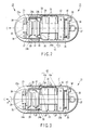
- FIG. 2 shows the sectional view showing the configuration of a first capsule endoscope according to the embodiment.
- a capsule case 23 of the first capsule endoscope 21 comprises of a transparent semiround distal end case 23a placed in the front end side, and a cylindrical proximal end case 23b with a semiround rear end passing infrared rays.
- the capsule case 23 contains a capsule endoscope described later, and is enclosed watertight.
- the capsule endoscope 21 advances in the cylinder axial direction indicated by C in FIG. 2 .
- a main body of the capsule endoscope is largely divided into an imaging unit to image the inner wall surface of a passage in a intracavital of a patient, a power supply unit to drive the imaging unit, an induction magnetic field generator to generate an induction magnetic field by the above-mentioned drive coil 11, a magnet to drive the capsule endoscope 21, and a transmission unit to transmit internal biological information including acquired image data to the receiving antenna 7.
- the imaging unit comprises imaging optics 26 having a fixed-focus lens, an imaging element 25 consisting of CMOS or CCD mounted on an imaging side substrate 24a, an illumination unit 39 consisting of a light controllable LED provided close to the imaging optics 26, and an image processing circuit 27 to perform predetermined image processing for an image signal from the imaging element 25 mounted on the imaging side substrate 24a in the rear side of the imaging element 25.
- the imaging side substrate 24a, power supply side substrate 24b, and front side substrate 43 for a battery are sealed with adhesive as a single unit 29 fixed with an adhesive.
- the power supply unit comprises a small battery 32 consisting of a button battery, a pair of substrate 43 (43a and 43b) for a battery provided with a not-shown power supply terminal to draw power from the small battery 32, a heat-shrink tube 34 to fix the small battery 32 just like holding by the battery substrate, a power supply side substrate 24b whose circuit wiring is electrically connected to the circuit wiring of the imaging side substrate 24 by a flexible substrate, and a power supply circuit 28 provided on the power supply side substrate 24b and powered by the small battery 32.
- the magnetic field generator comprises a magnet 30 provided on the perimeter of the adhesive fixed unit 29, a magnetic induction coil 31 provided through the magnet 30, and a capacitor 33 provided on the substrate for a battery in the front end side, composing a CL resonance circuit together with the magnetic induction coil 31.
- the magnetic induction coil 31 is shaped like a ring with a maximum outside diameter a little smaller than the inside diameter of the capsule case 23.
- the magnet 30 converges an external magnetic field in the magnetic induction coil 31.
- a material with high saturation magnetic flux density and permeability such as amorphous magnetic substance(magnet) and fine med (HITACHI KINZOKU) is suitable.
- Use of material shaped like a thin film provides an effect of reducing the volume of magnetic substance(magnet) when placed in a capsule endoscope.
- a circular drive magnet 42 is placed on the rear substrate 43b for a battery.
- a neodymium cobalt is suitable, but not limited to this material.
- the magnet 42 has an N-pole magnetized upward and an S-pole magnetized downward, so that the direction of magnetic lines of force becomes along the Z-axis direction.
- the transmission unit comprises a communication circuit 36 mounted on the rear side (the magnet 42 side) of a substrate 40 for transmission, an antenna 37 placed on the front surface side (the proximal end case 23b), a shielding part 35 to cover the exposed communication circuit 36 and to shield a magnetic force of the magnet 42, and an optical switch 38 which is mounted on the substrate 40 for transmission on the side provided with the antenna 27, and turns on/off the capsule endoscope.
- the magnetizing direction of the magnet 42 and the direction of the antenna 37 connected to the transmission circuit 36 are determined by changing the angle by 90 degrees. This is done for establishing the condition that the magnetic field generated by the magnet 42 enters at an angle displaced 90 degrees from the direction of the antenna 37. Therefore, the influence of the magnetic field from the magnet 42 upon the antenna 37 is reduced to minimum.
- the shielding part 35 is made of magnetic material, and has an effect to absorb the magnetic field close to the antenna 37. Therefore, the intensity of the magnetic field applied to the antenna 37 can be reduced, and the influence of the magnetic field on the radio communication between the transmission circuit 36 and antenna 37 can be decreased, and stable radio communication can be realized.
- the optical switch 38 is sensitive to infrared rays.
- the proximal end case 23b of the capsule case 23 is made of material to pass infrared rays (in the wavelength sensed by the optical switch) in at least the part close to the optical switch.
- infrared rays are applied to the optical switch 38 from a not-shown infrared rays emitter, the optical switch turns on, power is supplied from the small battery 32 through the power supply circuit, and imaging and transmission are started.
- the circuit of the optical switch 38 is configured to permit a toggle operation. Once infrared rays are applied, the capsule endoscope is kept on. It is permitted to add a configuration, which turns off the endoscope when infrared rays are applied in the on state.
- the influence of the strong magnetic field of the magnet 42 to the transmission circuit and radio circuit e.g., a noise is superposed, or a communicable distance is reduced
- clear image data with less noise can be sent to the receiving unit 9.
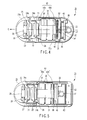
- FIG. 3 is a sectional view showing the configuration of a second capsule endoscope according to the embodiment.
- the second capsule endoscope is provided with a spiral part 25 formed by winding a wire with a circular cross section, on the perimeter of the capsule case 23, unlike the first capsule endoscope.
- the other parts are the same as the first capsule endoscope, and given the same reference numbers, and an explanation on these parts will be omitted.
- the power supply 2 for guidance coils impresses drive voltage to a guidance coil group, and generates the rotating magnetic field to the second capsule endoscope, and the second capsule endoscope 21 is rotated about the axis C in the direction R as shown in FIG. 3 .
- the second capsule endoscope 21 is moved forward or backward along the axis C, according to the direction of rotating the spiral part 25. Further, as it is possible to rotate the second capsule endoscope 21 as tilted the capsule endoscope can be moved forward or backward in the titled direction.
- the second capsule endoscope configured as above provides the same function and effect as the first capsule endoscope.
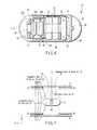
- FIG. 4 is a sectional view showing the configuration of a third capsule endoscope according to the embodiment.
- the third capsule endoscope is configured by replacing the positions of the magnet 42 and magnetic induction coil 31 in the first capsule endoscope.
- the other parts are the same as the first capsule endoscope, and given the same reference numbers, and an explanation on these parts will be omitted.
- FIG. 4 shows an example of configuration in which the induction coils 52 and 53 are placed in the directions of axes Z and Y. In the vicinity of the induction coils 52 and 53, capacitors 54 and 55 are placed to connect both ends of the induction coils for forming a LC resonance circuit, and adjusted to obtain a different resonance frequency.
- the crossed induction coils 52 and 53 generate an induction magnetic field by the magnetic field formed by the drive coil 11.
- the direction of the axis C i.e., the capsule endoscope advancing direction
- the direction of the axis C can be detected by obtaining the direction of each induction coil by a respective resonance frequency.
- a magnet 51 is arranged along the longitudinal axis (in the direction of the axis C) of the endoscope (with the N-pole set forward and S-pole set backward).
- a ring-shaped magnet or a barrel-shaped arrangement of stick magnets is provided on the perimeter of the bond fixed part 29.
- the third capsule endoscope configured as above can provide the same function and effect as the first capsule endoscope.
- FIG. 5 is a sectional view showing the configuration of a fourth capsule endoscope according to the embodiment.
- the fourth capsule endoscope is configured by replacing the magnet 42, transmission circuit 36 and antenna 37 in the first capsule endoscope.
- the other parts are the same as the first capsule endoscope, and given the same reference numbers, and an explanation on these parts will be omitted.
- the transmission circuit 36 and antenna 37 are enclosed by the shielding part 62, except the electromagnetic wave emitting direction of the antenna 37, a window for an optical switch is opened, and the optical switch 38 is placed there.
- a plurality of optical switch 38 may provided in different directions.
- the shielding part is provided adjacent to the substrate 43b for a battery, and a magnet 63 equivalent to the magnet 42 in the first capsule endoscope is provided in the rear of the substrate.
- a proximal end case 61 of the capsule case 23 is shaped not semiround, but flat in the rear end. The rear end may be shaped semiround.
- the fourth capsule endoscope configured as above can provide the same function and effect as the first capsule endoscope. Further, with this configuration, the magnetic lines of force close to the antenna 37 can be decreased in the intensity by penetrating through the shielding part 62. Therefore, deterioration of transmission performance can be prevented by reducing the influence of the magnetic field generated by the magnet 63 on the antenna 37.
- a magnetic substance as a shielding member is provided on the substrate by using of a thin film forming technique such as evaporating or sputtering. By this composition, the amount of the magnetic flux which enters in a substrate can be decreased. Therefore, the circuit formed in the capsule endoscope 21 can be prevented from malfunctioning due to an ill effect of a magnetic field of a magnet and induction coil.
- FIG. 6 is a sectional view showing the configuration of a fifth capsule endoscope according to the embodiment.
- the internal biological information (image data) is transmitted wirelessly (by radio waves) by using the communication circuit 36 and antenna 37.
- the fifth capsule endoscope uses a so-called electric field communication system. Namely, electrodes 64 and 65 exposed to the capsule case surface are provided, a current signal as internal biological information is flowed between the electrodes through a intracavital tissue to be examined, thereby generating an electric field in a living organism, and the internal biological information is received by an electric field sensor fit to the body surface of a patient, instead of the receiving antenna.
- the other parts are the same as the first capsule endoscope, and given the same reference numbers, and an explanation on these parts will be omitted.
- radio waves are not used as a communication medium, an ill effect on the receiving unit and transmission line is eliminated, a noise is hardly superposed, and a stable clear image is obtained, in addition to the function and effect obtained by the first capsule endoscope.
- the communication circuit and antenna can be omitted, the configuration becomes simple, and the capsule case can be miniaturized furthermore.
- FIG. 7 is a view showing an example of magnetic lines of force in a magnetic field viewed from the Y-axis direction upon guidance, with respect to the first capsule endoscope shown in FIG. 2 .
- This magnetic field is formed in a space surrounded by the guidance coils Z1, Z2, D2, D4, D6 and D8.
- the capsule endoscope is placed in this space with the distal end facing the direction from the guidance coil X2 to guidance coil X1 (in the X-axis direction) shown in FIG. 6 .
- the guidance coil Z1 In this magnetic field, the guidance coil Z1 generates a magnetic force upward in the Z-axis direction as shown in the drawing.
- the capsule endoscope 21 generates a magnetic field with the intensity weak in the lower direction (the guidance coil Z2 side) and strong in the upper direction.
- the magnet 42 in the capsule endoscope 21 is given an attractive force in the direction of a strong magnetic field, i.e., upward (called here an upward attractive force).
- the capsule endoscope 21 is moved up in the space.
- the guidance control unit 3 By controlling the strength of the upward attractive force by the guidance control unit 3, it is possible to make the state that gravity applied to the capsule endoscope 21 is cancelled.
- a magnetic field is formed in the guidance coils D2 and D4 as shown in FIG. 7 , and a pulling force for moving forward is generated. Therefore, when the magnetic fields of the guidance coils D2 and D4 are added on the magnetic field of the guidance coil Z1, the capsule endoscope 21 is moved forward while canceling the gravity applied to the endoscope itself.
- the capsule endoscope 21 is moved with its own weight (the mass of the capsule endoscope ⁇ acceleration of gravity) put on the intracavital tissue.
- the capsule endoscope 21 is reduced in its own weight, and moved in the state that a reaction force is weakened by viscosity, the endoscope can be equally moved even by a magnetic field with a lower intensity.
- this upward attractive force is excessively applied, the capsule endoscope 21 is unnecessarily floated from the intracavital tissue.
- the capsule endoscope 21 is floated from the intracavital tissue, the capsule endoscope comes close to the guidance coil Z1, the attractive force is weakened furthermore, and the capsule endoscope is suddenly attracted to the guidance coil Z1 and may be floated over the level desired by the user.
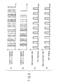
- FIG. 8(a) shows the intensity and generation timing of a magnetic field generated by the guidance coil Z1 to generate an upward attractive force in the Z-axis direction.
- FIG. 8(b) shows the intensity and generation timing of a magnetic field generated by the guidance coils D2 and D4 to generate a pulling force in the X-axis direction.
- FIG. 8(c) shows the timing for the position detector 6 to get signals (position and posture information signals) based on the induction magnetic field, from each sense coil 5.
- FIG. 8(a) shows the intensity and generation timing of a magnetic field generated by the guidance coil Z1 to generate an upward attractive force in the Z-axis direction.
- FIG. 8(b) shows the intensity and generation timing of a magnetic field generated by the guidance coils D2 and D4 to generate a pulling force in the X-axis direction.
- FIG. 8(c) shows the timing for the position detector 6 to get signals (position and posture information signals) based on the induction magnetic field, from each sense coil 5.
- FIG. 8(d) shows the timing of imaging internal biological information, and the timing of transmission and halt of transmission of internal biological information from the capsule endoscope 21 to the receiving unit 9.
- FIG. 8(e) shows the positions of the intracavital surface and endoscope in the Z-axis direction.
- the operation timing shown in FIG. 8 is set on the basis of the timing of imaging and transmitting image data by the capsule endoscope 21.
- the timing is not to be limited to this, and may be set as appropriate.
- the position of the capsule endoscope 21 is detected.
- the magnetic field intensity of the guidance coil Z1 is increased to raise the capsule endoscope (to n2) at the next timing.
- the intensity of generated magnetic field is lowered (n3) at the next timing.
- the relationship between the positions of the intracavital surface and capsule endoscope 21 in the Z-axis direction shown in FIG. 8(e) is conceptual, and actually, the capsule endoscope 21 substantially contacts the intracavital surface, and its weight is not substantially put on the intracavital surface (the endoscope does not sink by its own weight).
- an upward magnetic field in the Z-direction as shown in FIG. 7 is generated in the guidance coils D2 and D4.
- This magnetic field increases the gradient in the direction from the guidance coil X2 to the guidance coil X1, and becomes a pulling force for the capsule endoscope 21 to be pulled forward along the X-axis direction. Therefore, the capsule endoscope 21 is pulled forward by the guidance coils D2 and D4 with the gravity cancelled by the magnetic field of the guidance coil Z1, and is smoothly moved with less friction on the intracavital surface.
- the magnetic field generated by the guidance coils D2 and D4 is increased in the gradient at the position of the capsule endoscope, and the pulling force is increased. Namely, the moving speed of the capsule endoscope is increased. To move the capsule endoscope 21 at a constant speed, it is necessary to keep the propulsive force constant. Therefore, the intensity of the magnetic field generated by the guidance coils D2 and D4 is gradually decreased as shown in FIG. 8(b) .
- the magnetic field intensity is controlled based on the information about a position of the capsule endoscope 21, the gravity applied to the endoscope is cancelled, and the frictional force acting between the capsule endoscope 21 and intracavital tissue is decreased.
- the operation of guiding the endoscope can be made easy by decreasing the resistance caused by the movement, and the endoscope can be equally moved by a magnetic field with a lower intensity.
- the intensity of a magnetic field is controlled by the number of applying an on signal with a predetermined short pulse width to a drive signal applied to the guidance coils Z1, D2 and D4 in a period over which one magnetic field is generated.
- a magnetic field is generated like a pulse in each guidance coil, the intervals between the generated magnetic fields are controlled, and the intensity of each magnetic field is controlled as a result. This is realized by adding a known switching circuit to the power supply 2 for guidance coils.
- the guidance coils Z1, D2 and D4 generate a magnetic field like a pulse, and the intensity of each magnetic field is controlled by controlling the intervals between the generated magnetic fields.
- the configuration of the power supply for guidance coils can be made simple.
- An equivalent control method can be realized by using a PWM (Pulse Width Modulation) control method, which controls the on time (pulse width).
- the third control method shown in FIG. 10 realizes similar movement of the capsule endoscope 21 by driving different combinations of guidance coils, unlike the first control method.
- the third capsule endoscope shown in FIG. 4 is suitable for the third control method.
- the magnet 51 is arranged along the longitudinal axis (in the direction of the axis C) of the endoscope (with the N-pole set forward and S-pole set backward).
- the magnetic induction coils 52 and 53 are crossed (here, perpendicular to each other), and each induction coil is also arranged perpendicular to the magnetic lines of force of the magnet 51.
- a wire is wound around a core made of a needle-like magnetic substance, and the capacitors 54 and 55 are connected to the induction coils.
- the L-component or C-component of these two induction coils 52 and 53 is adjusted to have different resonance frequencies.
- the direction of magnetic lines of force from the magnet 51 can be arranged to be vertical to the longitudinal direction of the induction coils 52 and 53, and the influence of the magnetic field from the magnet 51 can be reduced to minimum, and the direction of the capsule endoscope can be determined by detecting the directions of two induction coils 52 and 53.
- the magnet incorporated in the capsule endoscope 21 shown in FIG. 10 is made to face the advancing direction (in the X-direction shown in FIG. 10 ) of the capsule endoscope 21, but the same control as shown in FIG. 7 is possible by adding a magnetic field as shown in FIG. 10 .
- a magnetic field as shown in FIG. 10 .
- the guidance coils D4 and D8 by generating a gradient magnetic field with the intensity gradually increased in the Z-axis direction (upward) by the guidance coils D4 and D8, an attractive force opposed to gravity is formed, and a gradient magnetic field is generated with the intensity gradually increased in the X-direction from the guidance coil X (to the left side in the drawing), and the capsule endoscope 21 can be moved in the X-direction with the gravity decreased.
- a first magnetic field advancing upward in the Z-axis direction is generated by using the guidance coils Z1 and Z2 among fourteen guidance coils X1, X2, Y, Y2, Z1, Z2, and D1 - D8, and a second magnetic field advancing to the left side in the drawing ( FIG. 11 ) in the X-axis direction is generated by using the guidance coils X1, and X2. It is possible to inline only the first magnetic field generated by the guidance coils Z1 and Z2.
- a magnetic field synthesized from the first and second magnetic fields is an external magnetic field H in FIG. 11 .
- the direction to the capsule endoscope 21 does not become parallel to the external magnetic field H, the capsule endoscope 21 turn to the down direction.
- magnetization of the magnet 42 is assumed to be M
- the external magnetic field is assumed to be H
- the angle formed by M and H is assumed to be ⁇
- the mass of the capsule endoscope 21 is assumed to be m
- the gravity acceleration is assumed to be g
- the angle formed by the Z-direction and the direction of the capsule endoscope 21 is assumed to be ⁇
- the gravity of the capsule endoscope 21 is assumed to be G
- the pivot of rotation when the capsule endoscope 21 is faced upward and ⁇ is changed is assumed to be P
- the distance from the pivot P is assumed to be 1.
- the pivot P can be the center of the semiround shape of the exterior end portion on the side not provided with the imaging optics 26 in the capsule endoscope 21.
- a magnetic field generated by the guidance coil group is controlled in this way.
- a target posture is set, and the dynamic torque estimation unit provided in the control unit estimates a torque (dynamic torque) generated in the capsule endoscope 21, based on the large of gravity applied to the capsule endoscope 21 in the target posture.
- the control unit calculates a magnetic field to generate a magnetic torque proportional to the estimated dynamic torque. (This magnetic field is directed to the direction ⁇ .)
- a magnetic torque is generated in the magnet 42 built into the capsule endoscope 21, and a torque (dynamic torque) generated in the capsule endoscope 21 by the gravity applied to the capsule endoscope 21 is proportional to the magnetic torque when the capsule endoscope 21 faces the direction ⁇ . Therefore, the capsule endoscope 21 can be directed to a desired direction (the direction ⁇ ) without being influenced by gravity.
- the capsule endoscope 21 When a magnetic field is formed in the guidance coil X1 to generate an attractive force to pull in the forward direction, for example, while the capsule endoscope 21 is existing in the tilt position in such a magnetic field, the capsule endoscope 21 is moved forward while keeping the tilt position in the state that only the proximal end portion of the capsule case 23 contacts the wall of the digestive organs. By moving in this way, the capsule endoscope easily rides over an uneven spot on a pathway on the wall of the digestive organs. Further, by superposing a magnetic field or an electric field to cancel gravity by using the guidance coil Z1, the capsule endoscope can be moved with a decreased frictional force.
- a desired position is realized by forming magnetic fields by the guidance coil group.
- the capsule endoscope 21 is floated on the water.
- buoyancy in addition to gravity is applied to the capsule endoscope 21.
- the buoyancy generates a torque (a dynamic torque) to be applied to the capsule endoscope, as is the gravity.
- the control unit calculates a magnetic field to generate a magnetic torque proportional to these two torques, and generates that magnetic field, thereby the capsule endoscope 21 can be controlled to adopt a target posture even if the capsule endoscope 21 is floated on the water.
- the induction coils X1/X2 and Z1/Z2 are used to incline the capsule endoscope to the tilt position as shown in FIG. 12 .
- the induction coils Z1 and Z2 are used to form a third magnetic field toward the Z-axis downward, and the induction coils Z1 and Z2 are used to form a fourth magnetic field toward the X-axis direction.
- the capsule endoscope 21 contains a magnet, but the magnet may be replaced by a magnetic substance having an axis easily magnetized.
- the magnetic substance is shaped like a stick or a plate.
- the magnetic substance may be a battery to supply power to the capsule endoscope 21.
- the magnetic substance may also be a shield to protect the electronic circuit built into the capsule endoscope 21.
- the dynamic torque estimation unit stores necessary items among the weight of the capsule endoscope 21 m ⁇ g, the center of gravity of the capsule endoscope 21, the position P of a pivot as a center of rotation of the capsule endoscope 21 (refer to FIGS. 11 and 12 ), the distance l from the pivot as a center of rotation of the capsule endoscope 21 to the position of the center of gravity (refer to FIG. 11 ), the buoyancy Ff (refer to FIG. 12 ), and the distance lf from an point of action of the buoyancy to the position P of the pivot as the center of rotation of the capsule endoscope 21 (refer to FIG. 12 ), as basic physical characteristics of the capsule endoscope 21.
- the capsule endoscope 21 projects from the water surface, and the part of the capsule endoscope 21 projected from the water surface is also changed if the posture of the capsule endoscope 21 is changed further.
- the part of the capsule endoscope 21 is changed by the buoyancy, the distance from the position P of the pivot as a center of rotation of the capsule endoscope 21 to the point of action of buoyancy, and the posture of the capsule endoscope 21, stored in the dynamic torque estimation unit.
- the dynamic torque estimation unit calculates a dynamic torque to be applied to the capsule endoscope 21 when the capsule endoscope 21 adopts the target posture. This calculation is made by the following formulas.
- the torque by gravity may be regarded as 0.
- the pivot as a center of rotation of the capsule endoscope 21 may be considered to be the center of gravity of the capsule endoscope, and the calculation can be simplified.
- the value of the torque determined by the above calculation is sent to the control unit.
- the control unit calculates a magnetic field to generate a magnetic torque proportion to the estimated dynamic torque.
- control unit can control the capsule endoscope to a target posture.
- These conditions surrounding the capsule endoscope 21 can be selected by the operator by providing a selector to input the control unit.
- the control unit stores the characteristics of the magnet 42 built into the capsule endoscope 21, concretely a magnet magnetizing strength M, and a posture information of magnet in the capsule endoscope 21.
- the magnet magnetizing direction is identical to the major axis of the capsule endoscope 21, but the posture of the capsule endoscope 21 can be controlled by referring the above magnet posture information, even if the magnet adopts a different posture.
- the posture of the medical device can be easily and accurately controlled.
Landscapes
- Health & Medical Sciences (AREA)
- Life Sciences & Earth Sciences (AREA)
- Surgery (AREA)
- Engineering & Computer Science (AREA)
- Animal Behavior & Ethology (AREA)
- Veterinary Medicine (AREA)
- Biomedical Technology (AREA)
- Heart & Thoracic Surgery (AREA)
- Medical Informatics (AREA)
- Molecular Biology (AREA)
- Nuclear Medicine, Radiotherapy & Molecular Imaging (AREA)
- General Health & Medical Sciences (AREA)
- Public Health (AREA)
- Physics & Mathematics (AREA)
- Biophysics (AREA)
- Optics & Photonics (AREA)
- Pathology (AREA)
- Radiology & Medical Imaging (AREA)
- Robotics (AREA)
- Endoscopes (AREA)
- Measurement Of The Respiration, Hearing Ability, Form, And Blood Characteristics Of Living Organisms (AREA)
Abstract
Description
- The present invention relates to a guidance system for an encapsulated medical device inserted into an intracavital for obtaining internal biological information, and a method of controlling the same.
- Among conventional medical devices for obtaining internal biological information, there is a known encapsulated medical device which periodically transmits image information while moving in an intracavital.
- As such an encapsulated medical device, a medical device guidance system configured to be magnetically guided has been proposed as disclosed in Jpn. Pat. Appln. KOKAI Publication No.
2004-255174 - Jpn. Pat. Appln. KOKAI Publication No.
2003-111720 - A first encapsulated medical device guidance system according to an embodiment of the invention has an internal biological information acquisition unit to acquire internal biological information; a communication unit to output the acquired internal biological information to the outside as an output signal; an encapsulated medical device having a magnet; a magnetic field generator which acts on the magnet, and generates a magnetic field for controlling at least one of the position and posture of the encapsulated medical device; and a control unit to control the magnetic field generator, wherein the control unit has a dynamic torque estimation unit to estimate a dynamic torque to be applied to the encapsulated medical device in a target posture, and controls a magnetic field generated from the magnetic field generator so that a magnetic torque generated by applying a magnetic field generated by the magnetic field generator to the magnet becomes substantially proportional to a dynamic torque estimated by the dynamic torque estimation unit.
- A second encapsulated medical device guidance system comprises an internal biological information acquisition unit to acquire internal biological information; a communication unit to output the acquired internal biological information to the outside as an output signal; an encapsulated medical device having a magnet; a magnetic field generator which acts on the magnet, and generates a magnetic field for controlling at least one of the position and posture of the encapsulated medical device; and a control unit to control the magnetic field generator, wherein the control unit controls the magnetic field generator which generates a magnetic field in a direction different from a desired direction of the encapsulated medical device generated by acting on a magnet, and controls the encapsulated medical device to face a desired direction, without being influenced by gravity.
- As a third embodiment of the invention, there is provided a method of guiding an encapsulated medical device, comprising a step of setting a target posture of an encapsulated medical device, a step of determining a dynamic torque to be applied to the encapsulated medical device, a step of calculating a magnetic field for generating a magnetic torque proportional to the dynamic torque, in a target posture of the encapsulated medical device, and a step of generating the calculated magnetic field in the vicinity of the encapsulated medical device.
-
-
FIG. 1 is a diagram showing the configuration of an encapsulated medical device guidance system according to an embodiment of the invention; -
FIG. 2 is a sectional view showing the configuration of a first capsule endoscope according to the embodiment; -
FIG. 3 is a sectional view showing the configuration of a second capsule endoscope according to the embodiment; -
FIG. 4 is a sectional view showing the configuration of a third capsule endoscope according to the embodiment; -
FIG. 5 is a sectional view showing the configuration of a fourth capsule endoscope according to the embodiment; -
FIG. 6 is a sectional view showing the configuration of a fifth capsule endoscope according to the embodiment; -
FIG. 7 is a view showing an example of a magnetic field viewed from the Y-axis direction related to guidance, with respect to the first capsule endoscope; -
FIG. 8 is a timing chart for explaining a first method of controlling an encapsulated medical device guidance system; -
FIG. 9 is a timing chart for explaining a second method of controlling an encapsulated medical device guidance system; -
FIG. 10 is a view showing an example of a magnetic field viewed from the Y-axis direction related to guidance, for explaining a third method of controlling a encapsulated medical device guidance system; -
FIG. 11 is a view for explaining a posture control considering gravity in a capsule endoscope; and -
FIG. 12 is a view for explaining a posture control considering buoyancy in a capsule endoscope. - Hereinafter, embodiments of the invention will be explained in detail with reference to the accompanying drawings.
- An explanation will be given on an encapsulated medical device guidance system according to one embodiment of the invention shown in
FIG. 1 . This encapsulated medical device guidance system is largely divided into an encapsulatedmedical device 21 shown inFIGS. 2 to 6 , and a magnetic guidance unit 1 which generates a magnetic field for guiding a capsule endoscope. As an encapsulated medical device in this embodiment, acapsule endoscope 21 is taken and explained as an example. - The magnetic guidance unit 1 mainly comprises a guidance coil group (X1, X2, Y1, Y2, Z1, Z2, D1, D2, D3, D4, D5, D6, D7, D8), a
power supply 2 for guidance coils, aguidance control unit 3, a controller 4, a sense coil unit 5 (5a - 5i), aposition detector 6, a receiving antenna unit 7 (7a, 7b, 7c), anantenna selector 8, a receiving unit 9, adisplay unit 10, adrive coil 11, and adrive coil driver 12. - Each of fourteen guidance coils X1, X2, Y1, Y2, Z1, Z2 and D1 - D8 has an air-core electromagnet, and forms an induction magnetic field generator. In this embodiment, the guidance coils are arranged on each side of a rectangular parallelepiped. As shown by the arrow in
FIG. 1 , the direction of moving thecapsule endoscope 21 forward and backward (or the direction of moving a human body to be examined) is assumed to be an X-axis direction, and the direction horizontally perpendicular to the X-axis is assumed to be a Y-axis direction, and a vertical (gravity) direction vertically perpendicular to the X-axis is assumed be a Z-axis direction. - In these axis directions, the guidance coils X1 and X2 are placed oppositely around the surfaces of front and rear sides, forming magnetic lines of force in the X-axis direction, and becoming vertical to the X-axis direction. The guidance coil X1 side is assumed to be front, and the guidance coil X2 side is assumed to be rear. Moving from the guidance coil X2 to the guidance coil X1 is assumed to be moving forward, and moving in the reverse direction is assumed to be moving backward.
- The guidance coils Y1 and Y2 are placed oppositely around the surfaces of both sides, forming magnetic lines of force in the Y-axis direction, and becoming vertical to the Y-axis direction. In one of these sides, two guidance coils D3 and D7 are arranged within the guidance coil Y1 so as to divide the plane into two parts, and in the other opposite side, two guidance coils D1 and D5 are arranged within the guidance coil Y2 so as to divide the plane into two parts.
- Similarly, the guidance coils Z1 and Z2 are placed oppositely around the top and bottom planes with respect to the Z-axis direction, forming magnetic lines of force in the Z-axis direction. In the top plane, two guidance coils D4 and D8 are arranged within the guidance coil Z1 so as to divide the plane into two parts, and in the opposite bottom plane, two guidance coils D2 and D6 are arranged within the guidance coil Z2 so as to divide the plane into two parts. The guidance coil Z1 side is assumed to be top, and the guidance coil Z2 side is assumed to be bottom. Moving from the guidance coil Z2 to the guidance coil Z1 is assumed to be moving upward, and moving in the reverse direction is assumed to be moving downward.
- An alternating magnetic field formed by the
drive coil 11 acts on themagnetic induction coil 31 and generates an induction current, and a magnetic field is generated from the magnetic induction coil. This alternating magnetic field includes one or more frequency components close to a resonance frequency generated by a coil (magnetic induction coil 31) andcapacitor 33 described later provided in thecapsule endoscope 21. - The generated induction magnetic field is detected by the
sense coils 5a - 5i, a signal including the position information is generated, and the signal is sent to theposition detector 6. Based on this signal, the position detector calculates the position and posture information in thecapsule endoscope 21. The position and posture information is sent to theguidance control unit 3, and used for calculation of a magnetic field to be generated by the guidance coil group. - The group of guidance coils X1, X2, Y1, Y2, Z1, Z2, and D1 - D8 is a first magnetic gradient generating means, which generates a magnetic gradient (a first magnetic gradient) to be applied to the magnet in the
capsule endoscope 21, and pulls the endoscope in a desired direction by moving in the longitudinal, horizontal and vertical directions. - The guidance coil Z1 eliminates the influence of gravity when pulling the
capsule endoscope 21 in a desired direction by moving up the endoscope by the above-mentioned guidance coil group, by generating a magnetic gradient (a second magnetic gradient) to be applied to the magnet in thecapsule endoscope 21 to cancel the force of moving down the endoscope moved by the gravity. The guidance coils D4 and D8 can also generate the same force as the guidance coil Z1. The guidance coil Z1 is a second magnetic gradient generating means to eliminate the influence of gravity when moving the endoscope in a desired direction. On the other hand, the guidance coil Z2 eliminates the influence of buoyancy when pulling thecapsule endoscope 21 in a desired direction by moving down the endoscope by the above-mentioned guidance coil group, by generating a magnetic field to be applied to the magnet in thecapsule endoscope 21 to cancel the force of moving up the endoscope moved by the buoyancy. The guidance coils D2 and D6 can also generate the same force as the guidance coil Z1. - Concretely, the oppositely placed guidance coils X1 and X2, Y1 and Y2, and Z1 and Z2 generate a uniform magnetic field within the space surrounded by these guidance coils when a magnetic field is generated in the same direction, and forms an oblique magnetic field when a magnetic field is generated in the opposite direction. The coils D1 - D8 can form a highly uniform magnetic field or a gradient magnetic field by driving appropriately. Therefore, by controlling these fourteen guidance coils, it is possible to generate a magnetic field having desired intensity and gradient within a desired space.
- In such arrangement of the guidance coil group, in addition to moving the
capsule endoscope 21 in the longitudinal, horizontal and vertical directions, it is possible to incline the endoscope to a position rising to the front, for example, by generating a magnetic field to tilt the distal end side up and proximal end side down, by combining the guidance coils X1, X2, Y1, Y2, Z1, Z2 and D1 - D8. - These guidance coils are connected to the
power supply 2 for guidance coils driven individually. Thepower supply 2 for guidance coils is controlled by the instruction from theguidance control unit 3, appropriately supplies power to a guidance coil necessary for generating a magnetic field, and generates a desired magnetic field in a desired space. - In this embodiment, a position detection system (a position detecting means) for detecting information about a position (a position in pace) of the
capsule endoscope 21 comprises adrive coil 11 for generating an induction magnetic field in the coil provided in thecapsule endoscope 21, asense coil group 5 for detecting the induction magnetic field generated in thecapsule endoscope 21, aposition detector 6 for generating the information about a position of the capsule endoscope 21 (the position in a three-dimensional space and the direction of the capsule endoscope) from the signal based on the induction magnetic field received by thesense coil group 5, and adrive coil driver 12 for driving thedrive coil 11 according to an instruction from theposition detector 6. - Nine
sense amplifiers 5a - 5i constituting thesense coil group 5 are arranged to be parallel to the side provided with the guidance coil Y1 and uniform in a plane, so that the correct position and posture of thecapsule endoscope 21 can be obtained. In this embodiment, the position related to the Z-axis is detected by providing a pair of oppositely placedsense coil set 5 and adrive coil 11. However, for detecting a three-dimensional position and posture, it is preferable to provide the pair on each of two crossing planes, for example, top and side planes. To increase the detection accuracy, a little more number of sense coils is preferable. - The
position detector 6 receives an instruction to specify a timing of detecting the information about a position from theguidance control unit 3, and drives thedrive coil driver 12 based on the instruction. Thedrive coil driver 12 generates a magnetic field by supplying an AC current to thedrive coil 11, and generates an induction magnetic field in thecapsule endoscope 21 in the magnetic field. Each sense coil of thesense coil group 5 detects a signal based on the induction magnetic field generated from thecapsule endoscope 21, and outputs it to theposition detector 6. Theposition detector 6 generates the position and posture information of thecapsule endoscope 21 from the signal based on the induction magnetic field, and outputs it to theguidance control unit 3. Theguidance control unit 3 determines a desired moving direction considering the position and posture information of thecapsule endoscope 21 from theposition detector 6, and instructs thepower supply 2 for guidance coils to generate a magnetic field suitable for moving in the desired moving direction. Thepower supply 2 for guidance coils feeds a current to the guidance coils X1, X2, Y1, Y2, Z1, Z2 and D1 - D8 according to the instruction from theguidance control unit 3. Therefore, a magnetic field suitable for that moving is generated by the guidance coils, and thecapsule endoscope 21 can be smoothly guided. - The controller 4 is an input unit, which instructs the advancing direction and inclination of the
capsule endoscope 21, by the operation of an input device by the operator, for example, tilting a joystick to a desired direction. In addition to a joystick, buttons arranged to instruct all directions, a touch panel, or a line-of-sight input unit is available as a means to operate the controller 4. - The
guidance control unit 3 receives an instruction signal from the controller 4, position and posture information from theposition detector 6, and signals related to the driving states of the guidance coils from the receiving unit 9, calculates a magnetic force (a magnetic field) for moving thecapsule endoscope 21 to a desired position, determines magnetic forces generated by the guidance coils X1, X2, Y1, Y2, Z1, Z2 and D1 - D8 for generating the magnetic force, and sends an instruction to the power supply for each guidance coil. - Further, the
guidance control unit 3 stops generation of a magnetic field during a communication period over which the image data acquired by thecapsule endoscope 21 is sent to the receiving unit 9. At the same time, during this communication period, theposition detector 6 drives thedrive coil 11 based on the instruction from the guidance control unit, and acquires the position information from thesense coil group 5. - Three receiving
antennas 7 are connected to the receiving unit through anantenna selector 8 for selecting the antennas. These receivingantennas 7 consist of a receivingantenna 7a (AX) for receiving communication data (internal biological information including image data) from the X-axis direction, a receivingantenna 7b (AY) for receiving internal biological information from the Y-axis direction, and a receiving antenna 7c (AZ) for receiving internal biological information from the Z-axis direction. The receivingantennas 7 can detect internal biological information in three axial directions. - The
antenna selector 8 selects theantennas antenna selector 8 receives the intensity, direction and gradient of a magnetic field generated by the guidance coil group at the position of each antenna, identifies a receiving antenna influenced minimum by the magnetic field, and selects that receiving antenna. By selecting such a receivingantenna 7, the communication between the receiving unit 9 andcapsule endoscope 21 can be stabilized. - The receiving unit 9 sends the
guidance control unit 3 the timing of receiving internal biological information from thecapsule endoscope 21. As described above, theguidance control unit 3 stops generation of an induction magnetic field by the guidance coil set and drivecoil 11, during the communication period for sending internal biological information (image data). Due to this stoppage, the receiving unit can receive the internal biological information from thecapsule endoscope 21 without being influenced by an induction magnetic field. By this stop period, the communication period does not overlap the moving operation and position detection period, and it is possible to eliminate a noise in the internal biological information caused by an induction magnetic field, or an influence of an induction magnetic field on the receiving antenna. - Therefore, this stop operation is useful in the point that image data is not influenced by a noise, and the receiving antenna is prevented from being influenced by an induction magnetic field, when a magnetic field generated close to the
capsule endoscope 21 has high intensity and much gradient, or when a magnetic field generated close the receivingantenna 7 has high intensity and much gradient. Further, even if a magnetic field generated by the guidance coil has high intensity, theposition detector 6 can be operated normally. - The
display unit 10 consists of a liquid crystal display, and displays an image generated by the receiving unit 9 and shot by thecapsule endoscope 21. When the image is displayed, the data such as imaging situation related to the displayed image may be displayed on the screen together with the image. - An explanation will now be given on first to fifth configuration examples in the
capsule endoscope 21 according to this embodiment with reference toFIG. 2 - FIG. 5 . -
FIG. 2 shows the sectional view showing the configuration of a first capsule endoscope according to the embodiment. - A
capsule case 23 of thefirst capsule endoscope 21 comprises of a transparent semirounddistal end case 23a placed in the front end side, and a cylindricalproximal end case 23b with a semiround rear end passing infrared rays. Thecapsule case 23 contains a capsule endoscope described later, and is enclosed watertight. Thecapsule endoscope 21 advances in the cylinder axial direction indicated by C inFIG. 2 . - An explanation will be given on the capsule endoscope itself.
- A main body of the capsule endoscope is largely divided into an imaging unit to image the inner wall surface of a passage in a intracavital of a patient, a power supply unit to drive the imaging unit, an induction magnetic field generator to generate an induction magnetic field by the above-mentioned
drive coil 11, a magnet to drive thecapsule endoscope 21, and a transmission unit to transmit internal biological information including acquired image data to the receivingantenna 7. - The imaging unit comprises
imaging optics 26 having a fixed-focus lens, animaging element 25 consisting of CMOS or CCD mounted on animaging side substrate 24a, anillumination unit 39 consisting of a light controllable LED provided close to theimaging optics 26, and animage processing circuit 27 to perform predetermined image processing for an image signal from theimaging element 25 mounted on theimaging side substrate 24a in the rear side of theimaging element 25. Theimaging side substrate 24a, powersupply side substrate 24b, andfront side substrate 43 for a battery are sealed with adhesive as asingle unit 29 fixed with an adhesive. - The power supply unit comprises a
small battery 32 consisting of a button battery, a pair of substrate 43 (43a and 43b) for a battery provided with a not-shown power supply terminal to draw power from thesmall battery 32, a heat-shrink tube 34 to fix thesmall battery 32 just like holding by the battery substrate, a powersupply side substrate 24b whose circuit wiring is electrically connected to the circuit wiring of the imaging side substrate 24 by a flexible substrate, and apower supply circuit 28 provided on the powersupply side substrate 24b and powered by thesmall battery 32. - The magnetic field generator comprises a
magnet 30 provided on the perimeter of the adhesive fixedunit 29, amagnetic induction coil 31 provided through themagnet 30, and acapacitor 33 provided on the substrate for a battery in the front end side, composing a CL resonance circuit together with themagnetic induction coil 31. - The
magnetic induction coil 31 is shaped like a ring with a maximum outside diameter a little smaller than the inside diameter of thecapsule case 23. Themagnet 30 converges an external magnetic field in themagnetic induction coil 31. As amagnet 30, a material with high saturation magnetic flux density and permeability, such as amorphous magnetic substance(magnet) and fine med (HITACHI KINZOKU), is suitable. Use of material shaped like a thin film provides an effect of reducing the volume of magnetic substance(magnet) when placed in a capsule endoscope. - A
circular drive magnet 42 is placed on therear substrate 43b for a battery. As a material of themagnet 42, a neodymium cobalt is suitable, but not limited to this material. Themagnet 42 has an N-pole magnetized upward and an S-pole magnetized downward, so that the direction of magnetic lines of force becomes along the Z-axis direction. By setting the polarity as above, thecapsule endoscope 21 is always directed to a predetermined direction with respect to the guidance coil group of the magnetic guidance unit 1. Therefore, the top and bottom of an obtained image can be absolutely determined. - The transmission unit comprises a
communication circuit 36 mounted on the rear side (themagnet 42 side) of asubstrate 40 for transmission, anantenna 37 placed on the front surface side (theproximal end case 23b), a shieldingpart 35 to cover the exposedcommunication circuit 36 and to shield a magnetic force of themagnet 42, and anoptical switch 38 which is mounted on thesubstrate 40 for transmission on the side provided with theantenna 27, and turns on/off the capsule endoscope. - In such arrangement, the magnetizing direction of the
magnet 42 and the direction of theantenna 37 connected to thetransmission circuit 36 are determined by changing the angle by 90 degrees. This is done for establishing the condition that the magnetic field generated by themagnet 42 enters at an angle displaced 90 degrees from the direction of theantenna 37. Therefore, the influence of the magnetic field from themagnet 42 upon theantenna 37 is reduced to minimum. - The shielding
part 35 is made of magnetic material, and has an effect to absorb the magnetic field close to theantenna 37. Therefore, the intensity of the magnetic field applied to theantenna 37 can be reduced, and the influence of the magnetic field on the radio communication between thetransmission circuit 36 andantenna 37 can be decreased, and stable radio communication can be realized. - The
optical switch 38 is sensitive to infrared rays. Theproximal end case 23b of thecapsule case 23 is made of material to pass infrared rays (in the wavelength sensed by the optical switch) in at least the part close to the optical switch. When infrared rays are applied to theoptical switch 38 from a not-shown infrared rays emitter, the optical switch turns on, power is supplied from thesmall battery 32 through the power supply circuit, and imaging and transmission are started. The circuit of theoptical switch 38 is configured to permit a toggle operation. Once infrared rays are applied, the capsule endoscope is kept on. It is permitted to add a configuration, which turns off the endoscope when infrared rays are applied in the on state. - By the configuration to cover the
communication circuit 36 by the shieldingpart 35, the influence of the strong magnetic field of themagnet 42 to the transmission circuit and radio circuit (e.g., a noise is superposed, or a communicable distance is reduced) can be reduced. Therefore, clear image data with less noise can be sent to the receiving unit 9. -
FIG. 3 is a sectional view showing the configuration of a second capsule endoscope according to the embodiment. - The second capsule endoscope is provided with a
spiral part 25 formed by winding a wire with a circular cross section, on the perimeter of thecapsule case 23, unlike the first capsule endoscope. The other parts are the same as the first capsule endoscope, and given the same reference numbers, and an explanation on these parts will be omitted. - In this configuration, the
power supply 2 for guidance coils impresses drive voltage to a guidance coil group, and generates the rotating magnetic field to the second capsule endoscope, and thesecond capsule endoscope 21 is rotated about the axis C in the direction R as shown inFIG. 3 . - The
second capsule endoscope 21 is moved forward or backward along the axis C, according to the direction of rotating thespiral part 25. Further, as it is possible to rotate thesecond capsule endoscope 21 as tilted the capsule endoscope can be moved forward or backward in the titled direction. The second capsule endoscope configured as above provides the same function and effect as the first capsule endoscope. -
FIG. 4 is a sectional view showing the configuration of a third capsule endoscope according to the embodiment. - The third capsule endoscope is configured by replacing the positions of the
magnet 42 andmagnetic induction coil 31 in the first capsule endoscope. The other parts are the same as the first capsule endoscope, and given the same reference numbers, and an explanation on these parts will be omitted. - Unlike the ring-shaped
magnetic induction coil 31 in the first capsule endoscope, two linear stick-shaped induction coils 52 and 53 are crossed in the third capsule endoscope.FIG. 4 shows an example of configuration in which the induction coils 52 and 53 are placed in the directions of axes Z and Y. In the vicinity of the induction coils 52 and 53,capacitors induction coils drive coil 11. As the induction coils 52 and 53 are vertical to the axis C and faced in different directions, the direction of the axis C (i.e., the capsule endoscope advancing direction) can be detected by obtaining the direction of each induction coil by a respective resonance frequency. Further, in the third capsule endoscope, amagnet 51 is arranged along the longitudinal axis (in the direction of the axis C) of the endoscope (with the N-pole set forward and S-pole set backward). Instead of thecircular magnet 42 in the first capsule endoscope, a ring-shaped magnet or a barrel-shaped arrangement of stick magnets is provided on the perimeter of the bond fixedpart 29. The third capsule endoscope configured as above can provide the same function and effect as the first capsule endoscope. -
FIG. 5 is a sectional view showing the configuration of a fourth capsule endoscope according to the embodiment. - The fourth capsule endoscope is configured by replacing the
magnet 42,transmission circuit 36 andantenna 37 in the first capsule endoscope. The other parts are the same as the first capsule endoscope, and given the same reference numbers, and an explanation on these parts will be omitted. - In the fourth capsule endoscope, the
transmission circuit 36 andantenna 37 are enclosed by the shieldingpart 62, except the electromagnetic wave emitting direction of theantenna 37, a window for an optical switch is opened, and theoptical switch 38 is placed there. A plurality ofoptical switch 38 may provided in different directions. The shielding part is provided adjacent to thesubstrate 43b for a battery, and amagnet 63 equivalent to themagnet 42 in the first capsule endoscope is provided in the rear of the substrate. Aproximal end case 61 of thecapsule case 23 is shaped not semiround, but flat in the rear end. The rear end may be shaped semiround. - The fourth capsule endoscope configured as above can provide the same function and effect as the first capsule endoscope. Further, with this configuration, the magnetic lines of force close to the
antenna 37 can be decreased in the intensity by penetrating through the shieldingpart 62. Therefore, deterioration of transmission performance can be prevented by reducing the influence of the magnetic field generated by themagnet 63 on theantenna 37. A magnetic substance as a shielding member is provided on the substrate by using of a thin film forming technique such as evaporating or sputtering. By this composition, the amount of the magnetic flux which enters in a substrate can be decreased. Therefore, the circuit formed in thecapsule endoscope 21 can be prevented from malfunctioning due to an ill effect of a magnetic field of a magnet and induction coil. -
FIG. 6 is a sectional view showing the configuration of a fifth capsule endoscope according to the embodiment. - In the first capsule endoscope, the internal biological information (image data) is transmitted wirelessly (by radio waves) by using the
communication circuit 36 andantenna 37. The fifth capsule endoscope uses a so-called electric field communication system. Namely,electrodes - With this configuration, radio waves are not used as a communication medium, an ill effect on the receiving unit and transmission line is eliminated, a noise is hardly superposed, and a stable clear image is obtained, in addition to the function and effect obtained by the first capsule endoscope. Further, the communication circuit and antenna can be omitted, the configuration becomes simple, and the capsule case can be miniaturized furthermore. By providing a speaker in the transmission circuit and connecting a microphone to the receiving unit, the same function and effect can be obtained by communication using a sound wave.
- Now, an explanation will be given on a first method of controlling an encapsulated medical device guidance system configured as described above.
-
FIG. 7 is a view showing an example of magnetic lines of force in a magnetic field viewed from the Y-axis direction upon guidance, with respect to the first capsule endoscope shown inFIG. 2 . This magnetic field is formed in a space surrounded by the guidance coils Z1, Z2, D2, D4, D6 and D8. The capsule endoscope is placed in this space with the distal end facing the direction from the guidance coil X2 to guidance coil X1 (in the X-axis direction) shown inFIG. 6 . - In this magnetic field, the guidance coil Z1 generates a magnetic force upward in the Z-axis direction as shown in the drawing. The
capsule endoscope 21 generates a magnetic field with the intensity weak in the lower direction (the guidance coil Z2 side) and strong in the upper direction. In the space having such a magnetic gradient, themagnet 42 in thecapsule endoscope 21 is given an attractive force in the direction of a strong magnetic field, i.e., upward (called here an upward attractive force). - Receiving the upward attractive force, the
capsule endoscope 21 is moved up in the space. By controlling the strength of the upward attractive force by theguidance control unit 3, it is possible to make the state that gravity applied to thecapsule endoscope 21 is cancelled. At this time, a magnetic field is formed in the guidance coils D2 and D4 as shown inFIG. 7 , and a pulling force for moving forward is generated. Therefore, when the magnetic fields of the guidance coils D2 and D4 are added on the magnetic field of the guidance coil Z1, thecapsule endoscope 21 is moved forward while canceling the gravity applied to the endoscope itself. - Namely, in the prior art, the
capsule endoscope 21 is moved with its own weight (the mass of the capsule endoscope × acceleration of gravity) put on the intracavital tissue. In contrast, in this embodiment, as thecapsule endoscope 21 is reduced in its own weight, and moved in the state that a reaction force is weakened by viscosity, the endoscope can be equally moved even by a magnetic field with a lower intensity. However, if this upward attractive force is excessively applied, thecapsule endoscope 21 is unnecessarily floated from the intracavital tissue. Once thecapsule endoscope 21 is floated from the intracavital tissue, the capsule endoscope comes close to the guidance coil Z1, the attractive force is weakened furthermore, and the capsule endoscope is suddenly attracted to the guidance coil Z1 and may be floated over the level desired by the user. - By controlling as indicated in the timing chart of
FIG. 8(a)-(e) , the capsule endoscope is moved while preventing such floating, and communication of internal biological information can be stably performed.FIG. 8(a) shows the intensity and generation timing of a magnetic field generated by the guidance coil Z1 to generate an upward attractive force in the Z-axis direction.FIG. 8(b) shows the intensity and generation timing of a magnetic field generated by the guidance coils D2 and D4 to generate a pulling force in the X-axis direction.FIG. 8(c) shows the timing for theposition detector 6 to get signals (position and posture information signals) based on the induction magnetic field, from eachsense coil 5.FIG. 8(d) shows the timing of imaging internal biological information, and the timing of transmission and halt of transmission of internal biological information from thecapsule endoscope 21 to the receiving unit 9.FIG. 8(e) shows the positions of the intracavital surface and endoscope in the Z-axis direction. - In this embodiment, the operation timing shown in
FIG. 8 is set on the basis of the timing of imaging and transmitting image data by thecapsule endoscope 21. The timing is not to be limited to this, and may be set as appropriate. - First, the position of the
capsule endoscope 21 is detected. When the position iscapsule endoscope 21 sinks below the intracavital surface (n1 inFIG. 8(e) ) and the magnetic field intensity is lower than a target value, the magnetic field intensity of the guidance coil Z1 is increased to raise the capsule endoscope (to n2) at the next timing. At this time, if thecapsule endoscope 21 is excessively raised, the intensity of generated magnetic field is lowered (n3) at the next timing. The relationship between the positions of the intracavital surface andcapsule endoscope 21 in the Z-axis direction shown inFIG. 8(e) is conceptual, and actually, thecapsule endoscope 21 substantially contacts the intracavital surface, and its weight is not substantially put on the intracavital surface (the endoscope does not sink by its own weight). - At this time, an upward magnetic field in the Z-direction as shown in
FIG. 7 is generated in the guidance coils D2 and D4. This magnetic field increases the gradient in the direction from the guidance coil X2 to the guidance coil X1, and becomes a pulling force for thecapsule endoscope 21 to be pulled forward along the X-axis direction. Therefore, thecapsule endoscope 21 is pulled forward by the guidance coils D2 and D4 with the gravity cancelled by the magnetic field of the guidance coil Z1, and is smoothly moved with less friction on the intracavital surface. - As the
capsule endoscope 21 advances, the magnetic field generated by the guidance coils D2 and D4 is increased in the gradient at the position of the capsule endoscope, and the pulling force is increased. Namely, the moving speed of the capsule endoscope is increased. To move thecapsule endoscope 21 at a constant speed, it is necessary to keep the propulsive force constant. Therefore, the intensity of the magnetic field generated by the guidance coils D2 and D4 is gradually decreased as shown inFIG. 8(b) . - As explained above, the magnetic field intensity is controlled based on the information about a position of the
capsule endoscope 21, the gravity applied to the endoscope is cancelled, and the frictional force acting between thecapsule endoscope 21 and intracavital tissue is decreased. By generating a gradient magnetic field inclined to the direction wanted to move thecapsule endoscope 21 in the state that the gravity is cancelled, the operation of guiding the endoscope can be made easy by decreasing the resistance caused by the movement, and the endoscope can be equally moved by a magnetic field with a lower intensity. - Next, an explanation will be given to a second method of controlling an encapsulated medical device guidance system.
- In this second control method, as shown in
FIG. 9(a) and (b) , the intensity of a magnetic field is controlled by the number of applying an on signal with a predetermined short pulse width to a drive signal applied to the guidance coils Z1, D2 and D4 in a period over which one magnetic field is generated. According to this method, a magnetic field is generated like a pulse in each guidance coil, the intervals between the generated magnetic fields are controlled, and the intensity of each magnetic field is controlled as a result. This is realized by adding a known switching circuit to thepower supply 2 for guidance coils. - With this configuration, the guidance coils Z1, D2 and D4 generate a magnetic field like a pulse, and the intensity of each magnetic field is controlled by controlling the intervals between the generated magnetic fields. By this control, the configuration of the power supply for guidance coils can be made simple. An equivalent control method can be realized by using a PWM (Pulse Width Modulation) control method, which controls the on time (pulse width).
- Next, an explanation will be given to a third method of controlling an encapsulated medical device guidance system. The third control method shown in
FIG. 10 realizes similar movement of thecapsule endoscope 21 by driving different combinations of guidance coils, unlike the first control method. The third capsule endoscope shown inFIG. 4 is suitable for the third control method. - In the third capsule endoscope, the
magnet 51 is arranged along the longitudinal axis (in the direction of the axis C) of the endoscope (with the N-pole set forward and S-pole set backward). The magnetic induction coils 52 and 53 are crossed (here, perpendicular to each other), and each induction coil is also arranged perpendicular to the magnetic lines of force of themagnet 51. Further, in the induction coils 52 and 53 in this embodiment, a wire is wound around a core made of a needle-like magnetic substance, and thecapacitors induction coils - In such a configuration, the direction of magnetic lines of force from the
magnet 51 can be arranged to be vertical to the longitudinal direction of the induction coils 52 and 53, and the influence of the magnetic field from themagnet 51 can be reduced to minimum, and the direction of the capsule endoscope can be determined by detecting the directions of twoinduction coils - The magnet incorporated in the
capsule endoscope 21 shown inFIG. 10 is made to face the advancing direction (in the X-direction shown inFIG. 10 ) of thecapsule endoscope 21, but the same control as shown inFIG. 7 is possible by adding a magnetic field as shown inFIG. 10 . Namely, by generating a gradient magnetic field with the intensity gradually increased in the Z-axis direction (upward) by the guidance coils D4 and D8, an attractive force opposed to gravity is formed, and a gradient magnetic field is generated with the intensity gradually increased in the X-direction from the guidance coil X (to the left side in the drawing), and thecapsule endoscope 21 can be moved in the X-direction with the gravity decreased. - Next, an explanation will be given on the posture control of the
capsule endoscope 21 by referring toFIG. 11 . - An explanation will be given by using the magnetic guidance unit 1 shown in
FIG. 1 and thethird capsule endoscope 21 shown inFIG. 4 . - An explanation will be given on the posture of the
capsule endoscope 21 inclined from the horizontal, for example, the tilt position where the distal end portion of the endoscope is raised, and the proximal end portion contacts the digestive organs. - To adopt this position, a first magnetic field advancing upward in the Z-axis direction is generated by using the guidance coils Z1 and Z2 among fourteen guidance coils X1, X2, Y, Y2, Z1, Z2, and D1 - D8, and a second magnetic field advancing to the left side in the drawing (
FIG. 11 ) in the X-axis direction is generated by using the guidance coils X1, and X2. It is possible to inline only the first magnetic field generated by the guidance coils Z1 and Z2. A magnetic field synthesized from the first and second magnetic fields is an external magnetic field H inFIG. 11 . However, as gravity is applied to thecapsule endoscope 21, the direction to thecapsule endoscope 21 does not become parallel to the external magnetic field H, thecapsule endoscope 21 turn to the down direction. At this time, magnetization of themagnet 42 is assumed to be M, the external magnetic field is assumed to be H, the angle formed by M and H is assumed to be δ, the mass of thecapsule endoscope 21 is assumed to be m, the gravity acceleration is assumed to be g, the angle formed by the Z-direction and the direction of thecapsule endoscope 21 is assumed to be θ, the gravity of thecapsule endoscope 21 is assumed to be G, the pivot of rotation when thecapsule endoscope 21 is faced upward and θ is changed is assumed to be P, and the distance from the pivot P is assumed to be 1. At this time, for simplicity, the pivot P can be the center of the semiround shape of the exterior end portion on the side not provided with theimaging optics 26 in thecapsule endoscope 21. By using the above-defined items, the following equation is established.
- According to the equation, a magnetic field may be added in the direction of Θ=θ-δ to direct the
capsule endoscope 21 to the θ direction (to adopt a target posture). A magnetic field generated by the guidance coil group is controlled in this way. Concretely, a target posture is set, and the dynamic torque estimation unit provided in the control unit estimates a torque (dynamic torque) generated in thecapsule endoscope 21, based on the large of gravity applied to thecapsule endoscope 21 in the target posture. Then, when thecapsule endoscope 21 adopts the target posture, the control unit calculates a magnetic field to generate a magnetic torque proportional to the estimated dynamic torque. (This magnetic field is directed to the direction Θ.) - By adding this magnetic field in the Θ direction, a magnetic torque is generated in the
magnet 42 built into thecapsule endoscope 21, and a torque (dynamic torque) generated in thecapsule endoscope 21 by the gravity applied to thecapsule endoscope 21 is proportional to the magnetic torque when thecapsule endoscope 21 faces the direction θ. Therefore, thecapsule endoscope 21 can be directed to a desired direction (the direction θ) without being influenced by gravity. - When a magnetic field is formed in the guidance coil X1 to generate an attractive force to pull in the forward direction, for example, while the
capsule endoscope 21 is existing in the tilt position in such a magnetic field, thecapsule endoscope 21 is moved forward while keeping the tilt position in the state that only the proximal end portion of thecapsule case 23 contacts the wall of the digestive organs. By moving in this way, the capsule endoscope easily rides over an uneven spot on a pathway on the wall of the digestive organs. Further, by superposing a magnetic field or an electric field to cancel gravity by using the guidance coil Z1, the capsule endoscope can be moved with a decreased frictional force. - When water remains in the intracavital, buoyancy equivalent to gravity may be generated. In such a state, the capsule endoscope is inclined to a position with the side having a heavier specific gravity to water faced downward, and imaging of a desired part may become difficult. Therefore, in this embodiment, a desired position is realized by forming magnetic fields by the guidance coil group.
- Only the difference from the above conditions is that the
capsule endoscope 21 is floated on the water. In this case, buoyancy in addition to gravity is applied to thecapsule endoscope 21. The buoyancy generates a torque (a dynamic torque) to be applied to the capsule endoscope, as is the gravity. - Therefore, the torque generated by the buoyancy is also determined in addition to the torque generated by the dynamic torque estimation unit generates in the
capsule endoscope 21, the control unit calculates a magnetic field to generate a magnetic torque proportional to these two torques, and generates that magnetic field, thereby thecapsule endoscope 21 can be controlled to adopt a target posture even if thecapsule endoscope 21 is floated on the water. For example, when water remains on the inner wall of the digestive organs and the distal end of thecapsule endoscope 21 is floated, the induction coils X1/X2 and Z1/Z2 are used to incline the capsule endoscope to the tilt position as shown inFIG. 12 . Namely, the induction coils Z1 and Z2 are used to form a third magnetic field toward the Z-axis downward, and the induction coils Z1 and Z2 are used to form a fourth magnetic field toward the X-axis direction. - By these magnetic fields, even if the distal end or proximal end portion of the
capsule endoscope 21 is floated by buoyancy, the position of the capsule endoscope can be easily controlled and a desired part can be imaged. Further, in this embodiment, thecapsule endoscope 21 contains a magnet, but the magnet may be replaced by a magnetic substance having an axis easily magnetized. In this case, the magnetic substance is shaped like a stick or a plate. Further, the magnetic substance may be a battery to supply power to thecapsule endoscope 21. The magnetic substance may also be a shield to protect the electronic circuit built into thecapsule endoscope 21. - Further, even if the
capsule endoscope 21 is not floated on the water but immersed in water, more exact posture control is possible by using the above scheme. Now, the configuration of the dynamic torque estimation unit will be explained more concretely. - The dynamic torque estimation unit stores necessary items among the weight of the capsule endoscope 21 m × g, the center of gravity of the
capsule endoscope 21, the position P of a pivot as a center of rotation of the capsule endoscope 21 (refer toFIGS. 11 and 12 ), the distance l from the pivot as a center of rotation of thecapsule endoscope 21 to the position of the center of gravity (refer toFIG. 11 ), the buoyancy Ff (refer toFIG. 12 ), and the distance lf from an point of action of the buoyancy to the position P of the pivot as the center of rotation of the capsule endoscope 21 (refer toFIG. 12 ), as basic physical characteristics of thecapsule endoscope 21. - Further, in the state that the
capsule endoscope 21 is floated on the water, thecapsule endoscope 21 projects from the water surface, and the part of thecapsule endoscope 21 projected from the water surface is also changed if the posture of thecapsule endoscope 21 is changed further. This means that the part of thecapsule endoscope 21 is changed by the buoyancy, the distance from the position P of the pivot as a center of rotation of thecapsule endoscope 21 to the point of action of buoyancy, and the posture of thecapsule endoscope 21, stored in the dynamic torque estimation unit. - Therefore, it is desirable to hold the information about the buoyancy, the distance from the position P of the pivot as a center of rotation of the
capsule endoscope 21 to the point of action of buoyancy, and the position of the pivot as a center of rotation of the capsule endoscope, as a lookup table corresponding to the function of the posture of thecapsule endoscope 21, or the posture of thecapsule endoscope 21. By these information and information about the object posture, the dynamic torque estimation unit calculates a dynamic torque to be applied to thecapsule endoscope 21 when thecapsule endoscope 21 adopts the target posture. This calculation is made by the following formulas. - In case of
FIG. 11 :
- Torque by gravity 0
- In case of
FIG. 12 :

- When the difference between the position of the pivot as a center of rotation of the
capsule endoscope 21 and the center of gravity position of thecapsule endoscope 21 is vary small (e.g., 2 mm or less, preferably approximately 1 mm), the torque by gravity may be regarded as 0. In this case, the pivot as a center of rotation of thecapsule endoscope 21 may be considered to be the center of gravity of the capsule endoscope, and the calculation can be simplified. - When the
capsule endoscope 21 is positioned under the water surface as shown inFIG. 11 :

- The value of the torque determined by the above calculation is sent to the control unit. When the
capsule endoscope 21 adopts the target posture, the control unit calculates a magnetic field to generate a magnetic torque proportion to the estimated dynamic torque. - By generating such a magnetic field, the control unit can control the capsule endoscope to a target posture. These conditions surrounding the
capsule endoscope 21 can be selected by the operator by providing a selector to input the control unit. - Next, the control unit will be explained in detail. The control unit stores the characteristics of the
magnet 42 built into thecapsule endoscope 21, concretely a magnet magnetizing strength M, and a posture information of magnet in thecapsule endoscope 21. In this embodiment, the magnet magnetizing direction is identical to the major axis of thecapsule endoscope 21, but the posture of thecapsule endoscope 21 can be controlled by referring the above magnet posture information, even if the magnet adopts a different posture. - As explained herein, the encapsulated medical device according to the embodiments of the invention, the posture of the medical device can be easily and accurately controlled. In particular, as an effect of the encapsulated medical device, it is possible to image a desired part by easily and accurately controlling the posture.
- The present invention is not limited to the described embodiments. Numerous modifications are possible without departing from the substance of the invention. Not all components of the embodiments may be mounted, and only the executable components may be used.
Claims (19)
- An encapsulated medical device guidance system comprising:an encapsulated medical device having an internal biological information acquisition unit to acquire internal biological information, a communication unit to output the acquired internal biological information to the outside as an output signal, and a magnet;a magnetic field generator which acts on the magnet, and generates a magnetic field for controlling at least one of the position and posture of the encapsulated medical device; anda control unit to control the magnetic field generator,wherein the control unit has a dynamic torque estimation unit to estimate a dynamic torque to be applied to the encapsulated medical device in a target posture, and controls a magnetic field generated from the magnetic field generator so that a magnetic torque generated by applying a magnetic field generated by the magnetic field generator to the magnet becomes substantially proportional to a dynamic torque estimated by the dynamic torque estimation unit.
- The system according to claim 1, wherein the dynamic torque estimation unit estimates a dynamic torque applied to the encapsulated medical device by gravity applied to the encapsulated medical device.
- The system according to claim 1, wherein the dynamic torque estimation unit estimates a dynamic torque applied to the encapsulated medical device by gravity applied to the encapsulated medical device and buoyancy applied to the encapsulated medical device.
- The system according to claim 1, wherein the dynamic torque estimation unit estimates a dynamic torque applied to the encapsulated medical device by buoyancy applied to the encapsulated medical device.
- The system according to claim 1, wherein the magnet is a magnet.
- The system according to claim 1, wherein the magnet is a battery.
- The system according to claim 1, wherein the dynamic torque estimation unit has at least one of information about the center of gravity of the encapsulated medical device, the weight of the encapsulated medical device, the pivot as a center of rotation of the encapsulated medical device, the distance from a point of action of buoyancy to the pivot, and the strength of buoyancy of the encapsulated medical device.
- The system according to claim 7, wherein the dynamic torque estimation unit has at least one of information about the distance from a point of action of buoyancy of the encapsulated medical device to the pivot, the strength of buoyancy of the encapsulated medical device, and the pivot as a center of rotation of the encapsulated medical device, as a variate to the posture of the encapsulated medical device.
- The system according to claim 7,
wherein the dynamic torque estimation unit estimates a dynamic torque by taking a spot in the vicinity of one end portion of the encapsulated medical device as a pivot which is a center of rotation of the encapsulated medical device. - The system according to claim 7, wherein the dynamic torque estimation unit estimates a dynamic torque by taking the center of gravity of the encapsulated medical device as a pivot which is a center of rotation of the encapsulated medical device.
- The system according to claim 5, wherein the control unit has at least one of information about the strength of magnetization of the magnet and the posture of the magnet in the encapsulated medical device.
- The system according to claim 1, wherein the magnetic field generator has at least two guidance coils to generate magnetic fields in different directions to the encapsulated medical device.
- The system according to claim 1, wherein the magnetic field generator generates also a magnetic field to pull the encapsulated medical device.
- An encapsulated medical device guidance system comprising:an encapsulated medical device having an internal biological information acquisition unit to acquire internal biological information,a communication unit to output the acquired internal biological information to the outside as an output signal, and a magnet;a magnetic field generator which acts on the magnet, and generates a magnetic field for controlling at least one of the position and posture of the encapsulated medical device; anda control unit to control the magnetic field generator,wherein the control unit generates a magnetic field in a direction different from a desired direction of the encapsulated medical device generated by the magnetic field generator by acting on the magnet, and controls the encapsulated medical device to face a desired direction, without being influenced by gravity.
- The encapsulated medical device guidance system according to claim 14, wherein the magnetic field generator generates also a magnetic field to pull the encapsulated medical device.
- A method of guiding an encapsulated medical device, comprising:a step of setting a target posture of an encapsulated medical device;a step of determining a dynamic torque to be applied to the encapsulated medical device;a step of calculating a magnetic field for generating a magnetic torque proportional to the dynamic torque, in a target posture of the encapsulated medical device; anda step of generating the calculated magnetic field in the vicinity of the encapsulated medical device.
- The method according to claim 16, wherein the dynamic torque is a torque generated by gravity applied to the encapsulated medical device.
- The method according to claim 16, wherein the dynamic torque is a torque generated by buoyancy applied to the encapsulated medical device.
- The method according to claim 16, wherein the dynamic torque is a torque generated by gravity applied to the encapsulated medical device, and buoyancy applied to the encapsulated medical device.
Applications Claiming Priority (2)
| Application Number | Priority Date | Filing Date | Title |
|---|---|---|---|
| JP2005376277 | 2005-12-27 | ||
| PCT/JP2006/326148 WO2007074888A1 (en) | 2005-12-27 | 2006-12-27 | Capsule type medical device guiding system and its control method |
Publications (3)
| Publication Number | Publication Date |
|---|---|
| EP1972255A1 true EP1972255A1 (en) | 2008-09-24 |
| EP1972255A4 EP1972255A4 (en) | 2010-03-03 |
| EP1972255B1 EP1972255B1 (en) | 2012-03-28 |
Family
ID=38218110
Family Applications (4)
| Application Number | Title | Priority Date | Filing Date |
|---|---|---|---|
| EP10014249A Withdrawn EP2335559A1 (en) | 2005-12-27 | 2006-12-27 | Encapsulated medical device guidance system |
| EP06843530A Not-in-force EP1972255B1 (en) | 2005-12-27 | 2006-12-27 | Capsule type medical device guiding system and its control method |
| EP06843528A Withdrawn EP1972253A4 (en) | 2005-12-27 | 2006-12-27 | GUIDING SYSTEM OF AN ENCAPSULATED MEDICAL DEVICE AND ITS CONTROL METHOD |
| EP11004808.9A Not-in-force EP2384687B1 (en) | 2005-12-27 | 2006-12-27 | Encapsulated medical device guidance system |
Family Applications Before (1)
| Application Number | Title | Priority Date | Filing Date |
|---|---|---|---|
| EP10014249A Withdrawn EP2335559A1 (en) | 2005-12-27 | 2006-12-27 | Encapsulated medical device guidance system |
Family Applications After (2)
| Application Number | Title | Priority Date | Filing Date |
|---|---|---|---|
| EP06843528A Withdrawn EP1972253A4 (en) | 2005-12-27 | 2006-12-27 | GUIDING SYSTEM OF AN ENCAPSULATED MEDICAL DEVICE AND ITS CONTROL METHOD |
| EP11004808.9A Not-in-force EP2384687B1 (en) | 2005-12-27 | 2006-12-27 | Encapsulated medical device guidance system |
Country Status (5)
| Country | Link |
|---|---|
| US (2) | US20080306340A1 (en) |
| EP (4) | EP2335559A1 (en) |
| JP (2) | JP5042037B2 (en) |
| CN (3) | CN101351143B (en) |
| WO (2) | WO2007074888A1 (en) |
Cited By (7)
| Publication number | Priority date | Publication date | Assignee | Title |
|---|---|---|---|---|
| DE102009007513A1 (en) * | 2009-02-05 | 2010-08-12 | Siemens Aktiengesellschaft | Detaching an endoscopy capsule from a surface of a fluid |
| DE102009060514A1 (en) * | 2009-12-23 | 2011-06-30 | Siemens Aktiengesellschaft, 80333 | Coil system and method for non-contact magnetic navigation of a magnetic body in a working space |
| DE102009060608A1 (en) * | 2009-12-23 | 2011-06-30 | Siemens Aktiengesellschaft, 80333 | Coil system and method for non-contact magnetic navigation of a magnetic body in a working space |
| DE102010006258A1 (en) * | 2010-01-28 | 2011-08-18 | Siemens Aktiengesellschaft, 80333 | Method for non-contact magnetic navigation |
| EP2481337A4 (en) * | 2010-03-26 | 2012-10-17 | Olympus Medical Systems Corp | GUIDING SYSTEM OF A CAPSULE MEDICAL DEVICE AND METHOD THEREOF |
| DE102011078500A1 (en) * | 2011-07-01 | 2013-01-03 | Siemens Aktiengesellschaft | Method for controlling endoscope capsule in liquid-filled cavity in stomach or intestinal tract of patient, involves exerting force on plane in direction depending on magnitude of another former force |
| US8528488B2 (en) | 2008-02-12 | 2013-09-10 | Siemens Aktiengesellschaft | Undercarriage cross member for a rail vehicle |
Families Citing this family (51)
| Publication number | Priority date | Publication date | Assignee | Title |
|---|---|---|---|---|
| WO2007077922A1 (en) | 2005-12-28 | 2007-07-12 | Olympus Medical Systems Corp. | Into-examinee introduction system and in-examinee observation method |
| JP5006596B2 (en) * | 2006-08-21 | 2012-08-22 | オリンパスメディカルシステムズ株式会社 | Capsule endoscope |
| JP5101513B2 (en) * | 2006-09-14 | 2012-12-19 | オリンパスメディカルシステムズ株式会社 | Medical guidance system |
| WO2009022667A1 (en) * | 2007-08-13 | 2009-02-19 | Olympus Medical Systems Corp. | Body interior observing system, and body interior observing method |
| WO2009041525A1 (en) * | 2007-09-26 | 2009-04-02 | Olympus Medical Systems Corp. | Introduction-into-subject system |
| DE102007051861B4 (en) * | 2007-10-30 | 2020-03-12 | Olympus Corporation | Method for guiding a capsule endoscope and endoscope system |
| JP5121523B2 (en) * | 2008-03-24 | 2013-01-16 | オリンパスメディカルシステムズ株式会社 | Position detection system |
| DE102008018723B3 (en) * | 2008-04-14 | 2009-07-16 | Siemens Aktiengesellschaft | Method for controlling the movement of an endoscopy capsule |
| JP5248911B2 (en) * | 2008-05-09 | 2013-07-31 | オリンパスメディカルシステムズ株式会社 | Capsule medical device |
| JP5415717B2 (en) * | 2008-06-19 | 2014-02-12 | オリンパスメディカルシステムズ株式会社 | Inspection apparatus and magnetic induction system using the same |
| EP2135545B1 (en) * | 2008-06-19 | 2013-07-31 | Olympus Medical Systems Corp. | Magnetically guiding system and method |
| JP5199020B2 (en) * | 2008-10-17 | 2013-05-15 | オリンパスメディカルシステムズ株式会社 | Magnetic induction system and method of operating magnetic induction system |
| US8241206B2 (en) * | 2008-07-08 | 2012-08-14 | Olympus Medical Systems Corp. | System for guiding capsule medical device |
| US20100010306A1 (en) * | 2008-07-08 | 2010-01-14 | Olympus Medical Systems Corp. | System for guiding capsule medical device |
| JP5385034B2 (en) * | 2008-07-08 | 2014-01-08 | オリンパスメディカルシステムズ株式会社 | Guidance system and guidance method |
| US8235888B2 (en) * | 2008-07-08 | 2012-08-07 | Olympus Medical Systems Corp. | System for guiding capsule medical device |
| DE102008049198B4 (en) | 2008-09-26 | 2017-03-02 | Siemens Healthcare Gmbh | Coil system, medical device and method for non-contact magnetic navigation of a magnetic body in a workspace |
| JP2010110432A (en) * | 2008-11-05 | 2010-05-20 | Olympus Corp | Wireless type intra-subject information acquisition apparatus |
| EP2353489A4 (en) * | 2008-11-28 | 2015-11-25 | Olympus Corp | ENCAPSULATED MEDICAL DEVICE GUIDING SYSTEM |
| DE102009010286B3 (en) * | 2009-02-24 | 2010-11-25 | Siemens Aktiengesellschaft | Device for contactless guiding of endoscopic capsule into operating space in body of patient for imaging internal organ, has magnetic body, where field strength is adjusted so that body is stably positioned in different positions |
| JP4751963B2 (en) * | 2009-03-10 | 2011-08-17 | オリンパスメディカルシステムズ株式会社 | Position detection system and method of operating position detection system |
| DE102009013354B4 (en) * | 2009-03-16 | 2011-02-17 | Siemens Aktiengesellschaft | Coil system, medical device and method for non-contact magnetic navigation of a magnetic body in a workspace |
| DE102009013352B4 (en) * | 2009-03-16 | 2011-02-03 | Siemens Aktiengesellschaft | Coil arrangements for guiding a magnetic object in a working space |
| WO2011055579A1 (en) * | 2009-11-09 | 2011-05-12 | オリンパスメディカルシステムズ株式会社 | Guiding system for capsule type medical device and method for guiding capsule type medical device |
| WO2011055578A1 (en) * | 2009-11-09 | 2011-05-12 | オリンパスメディカルシステムズ株式会社 | Capsule medical device guidance system |
| WO2011058800A1 (en) * | 2009-11-10 | 2011-05-19 | オリンパスメディカルシステムズ株式会社 | Capsule medical device guidance system and method for guiding capsule medical device |
| EP2509492A4 (en) * | 2009-12-08 | 2015-04-15 | Yehoshua Shachar | Diagnostic and therapeutic magnetic propulsion capsule and method for using the same |
| ES2710273T3 (en) * | 2010-01-22 | 2019-04-24 | Novineon Healthcare Tech Partners Gmbh | Capsule endoscope that includes magnetic drive |
| EP2537451A4 (en) * | 2010-02-18 | 2015-09-16 | Olympus Medical Systems Corp | POSITION DETECTING SYSTEM AND POSITION DETECTING METHOD |
| JP4897120B2 (en) * | 2010-03-05 | 2012-03-14 | オリンパスメディカルシステムズ株式会社 | Capsule endoscope activation system |
| EP2656773B1 (en) * | 2011-01-28 | 2016-10-05 | Olympus Corporation | Capsule medical device guiding system and magnetic field generating apparatus |
| DE102011004825B4 (en) * | 2011-02-28 | 2019-05-02 | Siemens Healthcare Gmbh | A method of controlling the transport of a magnetic moment endoscope capsule |
| KR101256408B1 (en) * | 2011-08-25 | 2013-04-25 | 전남대학교산학협력단 | A Micro-Robot System And Capsule Endoscope System For Diagnosing Of Tubular Digestive Organ |
| US10045713B2 (en) | 2012-08-16 | 2018-08-14 | Rock West Medical Devices, Llc | System and methods for triggering a radiofrequency transceiver in the human body |
| US9601930B2 (en) * | 2012-09-28 | 2017-03-21 | Broadcom Corporation | Power transmitting device having device discovery and power transfer capabilities |
| KR101410214B1 (en) * | 2012-11-23 | 2014-06-20 | 전남대학교산학협력단 | Capsule endoscope actuation control system, and a capsule endoscope system having the same |
| CN102973235A (en) * | 2012-11-27 | 2013-03-20 | 深圳市资福技术有限公司 | Capsule endoscope and direction control device thereof |
| CN103181748A (en) * | 2012-12-20 | 2013-07-03 | 深圳市资福技术有限公司 | Control system and control method for operation posture of capsule endoscope |
| CN105263391A (en) * | 2013-03-11 | 2016-01-20 | 基文影像公司 | Maneuvering coils setup for maneuvering a swallowable in-vivo device |
| EP3060102B1 (en) | 2013-10-22 | 2021-03-24 | Rock West Medical Devices, LLC | System to localize swallowable pill sensor with three transmitting elements |
| JP6521707B2 (en) * | 2014-07-10 | 2019-05-29 | キヤノン株式会社 | Puncture planning device and puncture system |
| JP6049951B2 (en) * | 2014-12-08 | 2016-12-21 | オリンパス株式会社 | Capsule endoscope system |
| EP3170442A4 (en) * | 2015-01-06 | 2018-04-04 | Olympus Corporation | Guiding apparatus and capsulated medical apparatus guiding system |
| JP6028131B1 (en) * | 2015-03-30 | 2016-11-16 | オリンパス株式会社 | Capsule endoscope system and magnetic field generator |
| US10478047B2 (en) * | 2016-09-23 | 2019-11-19 | Ankon Medical Technologies (Shanghai) Co., Ltd | System and method for using a capsule device |
| JP6483335B1 (en) * | 2017-06-13 | 2019-03-13 | オリンパス株式会社 | Antenna holder and antenna unit |
| WO2020252940A1 (en) * | 2019-06-17 | 2020-12-24 | 深圳硅基智控科技有限公司 | Magnetic control device of capsule endoscope and method for controlling movement of capsule endoscope in tissue cavity |
| CN110638416B (en) * | 2019-09-29 | 2022-06-21 | 北京华亘安邦科技有限公司 | Suspension control method and device of capsule endoscope |
| CN111184497B (en) * | 2020-04-08 | 2020-07-17 | 上海安翰医疗技术有限公司 | Capsule endoscope control method and system |
| CN112656353A (en) * | 2021-02-01 | 2021-04-16 | 河南省中医院(河南中医药大学第二附属医院) | Antifog type anorectal endoscope |
| CN113100690A (en) * | 2021-03-29 | 2021-07-13 | 谈斯聪 | In-vivo micro-robot device, and optimized treatment regulation and control system and method |
Family Cites Families (22)
| Publication number | Priority date | Publication date | Assignee | Title |
|---|---|---|---|---|
| US5681260A (en) * | 1989-09-22 | 1997-10-28 | Olympus Optical Co., Ltd. | Guiding apparatus for guiding an insertable body within an inspected object |
| US5654864A (en) * | 1994-07-25 | 1997-08-05 | University Of Virginia Patent Foundation | Control method for magnetic stereotaxis system |
| US6432041B1 (en) * | 1998-09-09 | 2002-08-13 | Olympus Optical Co., Ltd. | Endoscope shape detecting apparatus wherein form detecting processing is controlled according to connection state of magnetic field generating means |
| US6401723B1 (en) * | 2000-02-16 | 2002-06-11 | Stereotaxis, Inc. | Magnetic medical devices with changeable magnetic moments and method of navigating magnetic medical devices with changeable magnetic moments |
| WO2002082979A2 (en) * | 2001-04-18 | 2002-10-24 | Bbms Ltd. | Navigating and maneuvering of an in vivo vechicle by extracorporeal devices |
| DE10142253C1 (en) | 2001-08-29 | 2003-04-24 | Siemens Ag | endorobot |
| JP4088087B2 (en) * | 2002-03-08 | 2008-05-21 | オリンパス株式会社 | Medical magnetic guidance device |
| JP2004298560A (en) * | 2003-04-01 | 2004-10-28 | Olympus Corp | Capsule endoscope system |
| JP4503930B2 (en) * | 2003-01-30 | 2010-07-14 | オリンパス株式会社 | Medical equipment |
| JP4091004B2 (en) * | 2003-02-04 | 2008-05-28 | オリンパス株式会社 | Medical device guidance system |
| JP2004289560A (en) * | 2003-03-24 | 2004-10-14 | Sony Corp | Image recording / reproducing method and image recording / reproducing apparatus |
| DE10341092B4 (en) * | 2003-09-05 | 2005-12-22 | Siemens Ag | Installation for non-contact movement and / or fixation of a magnetic body in a working space using a magnetic coil system |
| DE10340925B3 (en) * | 2003-09-05 | 2005-06-30 | Siemens Ag | Magnetic coil system for non-contact movement of a magnetic body in a working space |
| DE10343494B4 (en) * | 2003-09-19 | 2006-06-14 | Siemens Ag | Magnetically navigable device for use in the field of medical endoscopy |
| DE10346678A1 (en) * | 2003-10-08 | 2005-05-12 | Siemens Ag | Endoscopy device comprising an endoscopy capsule or an endoscopy head with an image recording device and imaging method for such an endoscopy device |
| JP4414725B2 (en) * | 2003-10-28 | 2010-02-10 | オリンパス株式会社 | Capsule medical device |
| JP4515747B2 (en) * | 2003-10-27 | 2010-08-04 | オリンパス株式会社 | Capsule medical device |
| US7751866B2 (en) * | 2004-03-08 | 2010-07-06 | Olympus Corporation | Detecting system of position and posture of capsule medical device |
| JP5030392B2 (en) * | 2004-06-14 | 2012-09-19 | オリンパス株式会社 | Medical device position detection system and medical device guidance system |
| CN1332629C (en) * | 2004-09-02 | 2007-08-22 | 上海交通大学 | Active intestinal endoscope robot system |
| DE102006010730A1 (en) * | 2005-03-17 | 2006-09-28 | Siemens Ag | Device for determining position of navigatable object, comprises coils of background field coil system for generating background field, receiver, amplifiers for coupling the signals of the coils and agent to process and evaluate the signal |
| DE102007051861B4 (en) * | 2007-10-30 | 2020-03-12 | Olympus Corporation | Method for guiding a capsule endoscope and endoscope system |
-
2006
- 2006-12-27 JP JP2007552018A patent/JP5042037B2/en not_active Expired - Fee Related
- 2006-12-27 JP JP2007552971A patent/JP4891924B2/en not_active Expired - Fee Related
- 2006-12-27 EP EP10014249A patent/EP2335559A1/en not_active Withdrawn
- 2006-12-27 EP EP06843530A patent/EP1972255B1/en not_active Not-in-force
- 2006-12-27 CN CN2006800496316A patent/CN101351143B/en not_active Expired - Fee Related
- 2006-12-27 EP EP06843528A patent/EP1972253A4/en not_active Withdrawn
- 2006-12-27 WO PCT/JP2006/326148 patent/WO2007074888A1/en not_active Ceased
- 2006-12-27 EP EP11004808.9A patent/EP2384687B1/en not_active Not-in-force
- 2006-12-27 CN CN2006800496227A patent/CN101351141B/en not_active Expired - Fee Related
- 2006-12-27 CN CN201210156822.XA patent/CN102688014B/en not_active Expired - Fee Related
- 2006-12-27 WO PCT/JP2006/326146 patent/WO2007077896A1/en not_active Ceased
-
2008
- 2008-06-26 US US12/147,262 patent/US20080306340A1/en not_active Abandoned
- 2008-06-26 US US12/146,712 patent/US9039606B2/en not_active Expired - Fee Related
Cited By (11)
| Publication number | Priority date | Publication date | Assignee | Title |
|---|---|---|---|---|
| US8528488B2 (en) | 2008-02-12 | 2013-09-10 | Siemens Aktiengesellschaft | Undercarriage cross member for a rail vehicle |
| DE102009007513A1 (en) * | 2009-02-05 | 2010-08-12 | Siemens Aktiengesellschaft | Detaching an endoscopy capsule from a surface of a fluid |
| DE102009007513B4 (en) * | 2009-02-05 | 2011-02-10 | Siemens Aktiengesellschaft | Detaching an endoscopy capsule from a surface of a fluid |
| US9125576B2 (en) | 2009-02-05 | 2015-09-08 | Siemens Aktiengesellschaft | Separating endoscopy capsule from surface of liquid |
| DE102009060514A1 (en) * | 2009-12-23 | 2011-06-30 | Siemens Aktiengesellschaft, 80333 | Coil system and method for non-contact magnetic navigation of a magnetic body in a working space |
| DE102009060608A1 (en) * | 2009-12-23 | 2011-06-30 | Siemens Aktiengesellschaft, 80333 | Coil system and method for non-contact magnetic navigation of a magnetic body in a working space |
| DE102010006258A1 (en) * | 2010-01-28 | 2011-08-18 | Siemens Aktiengesellschaft, 80333 | Method for non-contact magnetic navigation |
| US9532705B2 (en) | 2010-01-28 | 2017-01-03 | Siemens Aktiengesellschaft | Method for contact-free magnetic navigation |
| EP2481337A4 (en) * | 2010-03-26 | 2012-10-17 | Olympus Medical Systems Corp | GUIDING SYSTEM OF A CAPSULE MEDICAL DEVICE AND METHOD THEREOF |
| DE102011078500A1 (en) * | 2011-07-01 | 2013-01-03 | Siemens Aktiengesellschaft | Method for controlling endoscope capsule in liquid-filled cavity in stomach or intestinal tract of patient, involves exerting force on plane in direction depending on magnitude of another former force |
| DE102011078500B4 (en) * | 2011-07-01 | 2015-01-15 | Siemens Aktiengesellschaft | Method and device for controlling an endoscope capsule |
Also Published As
| Publication number | Publication date |
|---|---|
| EP1972253A1 (en) | 2008-09-24 |
| CN101351143B (en) | 2012-07-04 |
| EP2335559A1 (en) | 2011-06-22 |
| WO2007074888A1 (en) | 2007-07-05 |
| CN101351141A (en) | 2009-01-21 |
| CN101351141B (en) | 2011-07-13 |
| WO2007077896A1 (en) | 2007-07-12 |
| JP5042037B2 (en) | 2012-10-03 |
| EP2384687B1 (en) | 2016-05-11 |
| CN102688014B (en) | 2015-03-18 |
| EP2384687A1 (en) | 2011-11-09 |
| US9039606B2 (en) | 2015-05-26 |
| US20080294006A1 (en) | 2008-11-27 |
| JP4891924B2 (en) | 2012-03-07 |
| JPWO2007077896A1 (en) | 2009-06-11 |
| US20080306340A1 (en) | 2008-12-11 |
| CN101351143A (en) | 2009-01-21 |
| CN102688014A (en) | 2012-09-26 |
| EP1972255B1 (en) | 2012-03-28 |
| EP1972255A4 (en) | 2010-03-03 |
| JPWO2007074888A1 (en) | 2009-06-04 |
| EP1972253A4 (en) | 2010-03-03 |
Similar Documents
| Publication | Publication Date | Title |
|---|---|---|
| EP1972255B1 (en) | Capsule type medical device guiding system and its control method | |
| EP1773230B1 (en) | Magnetic guiding medical system | |
| US8187166B2 (en) | Minimally invasive medical system employing a magnetically controlled endo-robot | |
| US8337396B2 (en) | Encapsulated medical device guidance system, and a method of controlling the same | |
| EP1723898A1 (en) | Capsule medical device position/posture detecting system | |
| EP1955644B1 (en) | Medical device position detecting system, medical device guiding system, and position detecting method for medical device | |
| WO2004089193A1 (en) | Capsule endoscope system | |
| JP2005103091A (en) | Guiding system of capsule type medical apparatus | |
| JP2007175188A5 (en) | ||
| EP2561797B1 (en) | Micro robot system and capsule endoscope system for examining a tubular digestive system |
Legal Events
| Date | Code | Title | Description |
|---|---|---|---|
| PUAI | Public reference made under article 153(3) epc to a published international application that has entered the european phase |
Free format text: ORIGINAL CODE: 0009012 |
|
| 17P | Request for examination filed |
Effective date: 20080723 |
|
| AK | Designated contracting states |
Kind code of ref document: A1 Designated state(s): DE FR GB |
|
| RIN1 | Information on inventor provided before grant (corrected) |
Inventor name: AOKI, ISAOC Inventor name: KIMURA, ATSUSHI C Inventor name: UCHIYAMA, AKIOC |
|
| DAX | Request for extension of the european patent (deleted) | ||
| RBV | Designated contracting states (corrected) |
Designated state(s): DE FR GB |
|
| A4 | Supplementary search report drawn up and despatched |
Effective date: 20100128 |
|
| 17Q | First examination report despatched |
Effective date: 20100423 |
|
| RIC1 | Information provided on ipc code assigned before grant |
Ipc: A61B 1/00 20060101AFI20101117BHEP |
|
| REG | Reference to a national code |
Ref country code: DE Ref legal event code: R079 Ref document number: 602006028532 Country of ref document: DE Free format text: PREVIOUS MAIN CLASS: A61B0001000000 Ipc: A61B0001040000 |
|
| GRAP | Despatch of communication of intention to grant a patent |
Free format text: ORIGINAL CODE: EPIDOSNIGR1 |
|
| RIC1 | Information provided on ipc code assigned before grant |
Ipc: A61B 1/04 20060101AFI20110926BHEP |
|
| GRAS | Grant fee paid |
Free format text: ORIGINAL CODE: EPIDOSNIGR3 |
|
| GRAA | (expected) grant |
Free format text: ORIGINAL CODE: 0009210 |
|
| AK | Designated contracting states |
Kind code of ref document: B1 Designated state(s): DE FR GB |
|
| REG | Reference to a national code |
Ref country code: GB Ref legal event code: FG4D |
|
| REG | Reference to a national code |
Ref country code: DE Ref legal event code: R096 Ref document number: 602006028532 Country of ref document: DE Effective date: 20120524 |
|
| PLBE | No opposition filed within time limit |
Free format text: ORIGINAL CODE: 0009261 |
|
| STAA | Information on the status of an ep patent application or granted ep patent |
Free format text: STATUS: NO OPPOSITION FILED WITHIN TIME LIMIT |
|
| 26N | No opposition filed |
Effective date: 20130103 |
|
| REG | Reference to a national code |
Ref country code: DE Ref legal event code: R097 Ref document number: 602006028532 Country of ref document: DE Effective date: 20130103 |
|
| GBPC | Gb: european patent ceased through non-payment of renewal fee |
Effective date: 20121227 |
|
| PG25 | Lapsed in a contracting state [announced via postgrant information from national office to epo] |
Ref country code: GB Free format text: LAPSE BECAUSE OF NON-PAYMENT OF DUE FEES Effective date: 20121227 |
|
| PGFP | Annual fee paid to national office [announced via postgrant information from national office to epo] |
Ref country code: FR Payment date: 20141208 Year of fee payment: 9 |
|
| REG | Reference to a national code |
Ref country code: DE Ref legal event code: R082 Ref document number: 602006028532 Country of ref document: DE Representative=s name: WUESTHOFF & WUESTHOFF, PATENTANWAELTE PARTG MB, DE Ref country code: DE Ref legal event code: R081 Ref document number: 602006028532 Country of ref document: DE Owner name: OLYMPUS CORPORATION, JP Free format text: FORMER OWNERS: OLYMPUS CORPORATION, TOKYO, JP; OLYMPUS MEDICAL SYSTEMS CORP., TOKYO, JP |
|
| REG | Reference to a national code |
Ref country code: FR Ref legal event code: ST Effective date: 20160831 |
|
| PG25 | Lapsed in a contracting state [announced via postgrant information from national office to epo] |
Ref country code: FR Free format text: LAPSE BECAUSE OF NON-PAYMENT OF DUE FEES Effective date: 20151231 |
|
| PGFP | Annual fee paid to national office [announced via postgrant information from national office to epo] |
Ref country code: DE Payment date: 20161220 Year of fee payment: 11 |
|
| REG | Reference to a national code |
Ref country code: DE Ref legal event code: R119 Ref document number: 602006028532 Country of ref document: DE |
|
| PG25 | Lapsed in a contracting state [announced via postgrant information from national office to epo] |
Ref country code: DE Free format text: LAPSE BECAUSE OF NON-PAYMENT OF DUE FEES Effective date: 20180703 |