EP1972179B1 - Hearing aid system - Google Patents
Hearing aid system Download PDFInfo
- Publication number
- EP1972179B1 EP1972179B1 EP06838891.7A EP06838891A EP1972179B1 EP 1972179 B1 EP1972179 B1 EP 1972179B1 EP 06838891 A EP06838891 A EP 06838891A EP 1972179 B1 EP1972179 B1 EP 1972179B1
- Authority
- EP
- European Patent Office
- Prior art keywords
- vibrator
- unit
- energy
- hearing aid
- aid system
- Prior art date
- Legal status (The legal status is an assumption and is not a legal conclusion. Google has not performed a legal analysis and makes no representation as to the accuracy of the status listed.)
- Active
Links
Images


Classifications
-
- H—ELECTRICITY
- H04—ELECTRIC COMMUNICATION TECHNIQUE
- H04R—LOUDSPEAKERS, MICROPHONES, GRAMOPHONE PICK-UPS OR LIKE ACOUSTIC ELECTROMECHANICAL TRANSDUCERS; ELECTRIC HEARING AIDS; PUBLIC ADDRESS SYSTEMS
- H04R25/00—Electric hearing aids
- H04R25/60—Mounting or interconnection of hearing aid parts, e.g. inside tips, housings or to ossicles
- H04R25/604—Mounting or interconnection of hearing aid parts, e.g. inside tips, housings or to ossicles of acoustic or vibrational transducers
- H04R25/606—Mounting or interconnection of hearing aid parts, e.g. inside tips, housings or to ossicles of acoustic or vibrational transducers acting directly on the eardrum, the ossicles or the skull, e.g. mastoid, tooth, maxillary or mandibular bone, or mechanically stimulating the cochlea, e.g. at the oval window
-
- H—ELECTRICITY
- H04—ELECTRIC COMMUNICATION TECHNIQUE
- H04R—LOUDSPEAKERS, MICROPHONES, GRAMOPHONE PICK-UPS OR LIKE ACOUSTIC ELECTROMECHANICAL TRANSDUCERS; ELECTRIC HEARING AIDS; PUBLIC ADDRESS SYSTEMS
- H04R25/00—Electric hearing aids
- H04R25/55—Electric hearing aids using an external connection, either wireless or wired
- H04R25/554—Electric hearing aids using an external connection, either wireless or wired using a wireless connection, e.g. between microphone and amplifier or using Tcoils
-
- H—ELECTRICITY
- H04—ELECTRIC COMMUNICATION TECHNIQUE
- H04R—LOUDSPEAKERS, MICROPHONES, GRAMOPHONE PICK-UPS OR LIKE ACOUSTIC ELECTROMECHANICAL TRANSDUCERS; ELECTRIC HEARING AIDS; PUBLIC ADDRESS SYSTEMS
- H04R2225/00—Details of deaf aids covered by H04R25/00, not provided for in any of its subgroups
- H04R2225/67—Implantable hearing aids or parts thereof not covered by H04R25/606
-
- H—ELECTRICITY
- H04—ELECTRIC COMMUNICATION TECHNIQUE
- H04R—LOUDSPEAKERS, MICROPHONES, GRAMOPHONE PICK-UPS OR LIKE ACOUSTIC ELECTROMECHANICAL TRANSDUCERS; ELECTRIC HEARING AIDS; PUBLIC ADDRESS SYSTEMS
- H04R2460/00—Details of hearing devices, i.e. of ear- or headphones covered by H04R1/10 or H04R5/033 but not provided for in any of their subgroups, or of hearing aids covered by H04R25/00 but not provided for in any of its subgroups
- H04R2460/13—Hearing devices using bone conduction transducers
-
- H—ELECTRICITY
- H04—ELECTRIC COMMUNICATION TECHNIQUE
- H04R—LOUDSPEAKERS, MICROPHONES, GRAMOPHONE PICK-UPS OR LIKE ACOUSTIC ELECTROMECHANICAL TRANSDUCERS; ELECTRIC HEARING AIDS; PUBLIC ADDRESS SYSTEMS
- H04R25/00—Electric hearing aids
- H04R25/45—Prevention of acoustic reaction, i.e. acoustic oscillatory feedback
- H04R25/456—Prevention of acoustic reaction, i.e. acoustic oscillatory feedback mechanically
Definitions
- the present invention relates to a hearing aid system for providing direct bone conduction hearing.
- Bone conduction is the principle of transmitting vibrations via the skull bone to the inner ear, i.e. the cochlea.
- the vibrations are transmitted through the skull bone, and since the cochlea is a winding in the bone, the vibrations go directly to the cochlea.
- the normal transmission chain with the ossicular bones for example the stapes, is not directly involved in the transmission of the vibrations to the cochlea.
- Hearing aids that for example connect to the middle ear ossicular bones are not bone conduction hearing aids.
- a direct bone conduction hearing aid is a type of bone conduction hearing aid where the vibrator of the hearing aid is firmly connected to the skull bone so that the vibrations from the vibrator do not have to go through the skin to reach the skull bone.
- a traditional bone conductor where the vibrations has to go through the skin to reach the skull bone is less efficient than a direct bone conductor since the vibrations will be damped when going through the skin.
- the most common type of direct bone conductors consists of an external hearing aid with a vibrator that is connected to a skin-penetrating abutment that is connected to a screw shaped fixture anchored in the skull bone. These patients have often problems with skin infections due to the permanent skin-penetrating abutment.
- Stenfelt has a vibrator unit positioned in the mastoid cavity and the anchoring fixture is anchored deep in the bottom of the mastoid cavity.
- the problem with this anchoring is that the bone in this area is very soft so the anchoring will be quite weak. If the anchoring fixture is placed deep in the mastoid cavity it will also be difficult to get access to the anchoring fixture if the vibrator unit needs to be removed.
- the direct bone conduction hearing aid system of the present invention has a vibrator that is placed in an implanted vibrator unit.
- the implanted vibrator unit is positioned in the mastoid cavity.
- a mounting arm extends from the lateral end of the implanted vibrator unit to a lateral side (i.e. the outside) of the skull bone over part of the skull bone surface where the mounting arm is fixated to the skull bone via an anchoring fixture.
- the anchoring fixture is easy to mount and access since it is mounted to the skull bone from a lateral position.
- the anchoring fixture is preferably a screw shaped osseointegrating fixture that is screwed into the skull through the skull bone surface.
- the vibrator that needs some space is located in the mastoid cavity where there is room for it.
- the vibrator via the mounting arm, the vibrator is fixated to the cortical skull bone that has a high bone quality and where the anchoring fixture is easy to mount and access.
- the present invention has a microphone system that picks up audio sound and converts it into an electrical microphone signal.
- the microphone or microphone system of the hearing aid system may be either implanted, placed in an external transmitter unit, placed in an external battery unit or placed in a separate external microphone unit.
- a preamplifier with the audio signal processing is usually placed together with the microphone.
- the signal from the microphone may be transmitted to the implanted electronics either through the inductive energy link or a separate transmission link.
- An FM or AM link could for example be used for this transmission.
- the present invention also has an amplifier that amplifies the electrical microphone signal and drives a vibrator that generates audio vibrations.
- This amplifier is an output amplifier.
- the implanted vibrator unit that has a housing and the vibrator is fixated to the housing.
- the mounting arm is preferably fixated at a lateral end of the housing of the implanted vibrator unit.
- the anchoring fixture has a bone fixation portion that is anchored in the skull bone through a lateral skull bone surface.
- the vibrator is mechanically connected to the skull bone via the housing of the implanted vibrator unit, the mounting arm and the anchoring fixture.
- the audio vibrations from the vibrator go through the mounting arm and the anchoring fixture to the skull bone;
- the present invention has an implanted energy-receiving unit with an energy-receiving inductive coil that picks up electromagnetic energy and converts it into an electric supply voltage and current.
- the energy from the electric supply voltage and current is used to supply the amplifier, either directly or the energy may be stored in for example a battery or capacitor before it is used.
- a vibrator supply cable connects the implanted energy-receiving unit to the implanted vibrator unit;
- the implanted vibrator unit is separate from the implanted energy-receiving unit. This is very important since the ferromagnetic material that is often used in a vibrator may severely affect the function of the inductive link between an external device and the energy-receiving inductive coil.
- the vibrator usually works at audio frequencies whereas the inductive link often works at for example 0,5 MHz.
- the vibrator may also affect the permanent magnet arrangement that is often used to hold an external transmitter unit in place against the skin over the energy-receiving inductive coil.
- the electronics that is required in the implanted arrangement may be placed either in the implanted energy-receiving unit, in the implanted vibrator unit or in a separate unit on the cable that goes from the implanted energy-receiving unit to the implanted vibrator unit.
- the implanted electronics includes the amplifier that drives the vibrator.
- the present invention offers a unique solution for a safe, aesthetic and reliable implantable direct bone conduction hearing aid system.
- the vibrator may be any type of vibrator, for example a piezoelectric vibrator, however a preferred solution is an electromagnetic vibrator.
- Most electromagnetic vibrators for direct bone conductors has one portion that oscillates in relation to the skull bone and one portion that is mechanically fix in relation to the skull bone.
- the coil is mounted in the portion of the vibrator that oscillates in relation to the skull bone.
- This solution may be a compact and space saving solution also for the present invention.
- the supply cables that go through the housing of the vibrator unit will in this case be flexible when going over to the coil since the coil is moving with the vibrations in relation to the housing of the vibrator unit.
- Such flexible lead can be done with for example litz wires or etched flex film.
- the vibrator unit is however designed so that the vibrator coil is mechanically fix in relation to the housing of the vibrator unit.
- the other portion of the vibrator, where the coil is not placed, is the portion that oscillates in relation to the skull bone.
- the wires that go through the housing of the vibrator unit to the coil do not need to be flexible and there will be no wear and tear on these cables.
- extra mass may be required on the oscillating portion to make sure that the vibrator has the right frequency characteristics.
- the hearing aid system has an implanted battery.
- the external transmitter unit is only needed when charging the battery.
- the battery may be placed in the implanted energy-receiving unit or in a separate implanted battery unit that is connected with a cable to the implanted energy-receiving unit.
- the hearing aid system of the present invention has an external transmitter unit with a battery and an energy transmitting inductive coil that continuously transmits energy to the implanted energy-receiving unit.
- the external transmitter unit may be connected to the implanted energy-receiving unit with a magnetic attachment.
- the hearing aid system of the present invention has an external transmitter unit, an external battery unit and a cable that connects the external transmitter unit and the external battery unit.
- the external unit has an energy transmitting inductive coil that continuously transmits energy to the implanted energy-receiving unit.
- the external battery unit may be a body worn unit or a unit designed as an ear hook that can be worn as a behind the ear hearing aid. This is the best solution for patients who need a powerful device where the battery lasts longer.
- the battery is placed in the external transmitter unit or in an external battery unit it would be most efficient to place the microphone in either the external transmitter unit or in the external battery unit.
- the implanted energy-receiving unit has holes for receiving a fixation screw that can be fixated to the skull bone.
- the traditional way of anchoring an implantable unit like this is to suture it to the skull bone. This procedure is however a quite time consuming part of the surgical procedure.
- a solution where the fixation is done with fixation screws will make the surgical procedure quicker and simpler. This fixation will also be more safe and stable since this anchoring screw can be done with an osseo-integrating function.
- the fixation screw may go either directly through the hole in the implanted energy-receiving unit into the skull bone or it may be a design where the fixation screw in the bone has a threaded inner hole to receive a connection screw that goes through the hole in the implanted energy-receiving unit. It is of course possible to have more than one hole and more than one fixation screw. Probably two holes and two fixation screws is the ideal to get a stable fixation without too many screws.
- the vibrator supply cable has a connector so that the implanted energy-receiving unit can be disconnected from the implanted vibrator unit. In this way it is possible to change one of the implanted vibrator unit or the implanted energy-receiving unit without having to change the other unit.
- the anchoring fixture has a threaded inner hole to receive a connection screw that fixates the mounting arm to the anchoring fixture. In this way there is no initial pressure from the mounting arm against the skull bone and it is easy to change the vibrator unit without having to remove the anchoring fixture from the bone.
- the implanted electronics includes an energy storing capacitor with a capacitance greater than 1 mF.
- an energy storing capacitor with a capacitance greater than 1 mF.
- the implanted vibrator unit, the mounting arm and the anchoring fixture is made in one unit.
- the mounting of the implanted vibrator unit can be easier during surgery.
- Either the implanted vibrator unit, the mounting arm and the anchoring fixture is made in one integrated unit so that they can not be taken apart easily, or they can be delivered as a pre mounted assembly that is easy to install but can still be separated if necessary.
- the anchoring fixture may for example have a conical shape so that it can be pressed into a hole in the bone to get an initial stability.
- the microphone system includes two microphones and a programmable microphone processing circuit where the sensitivity for sound coming from the front compared to sound coming from the rear is variable by programming the circuit digitally in a programmable circuit.
- This type of microphone system may also be based on more than two microphones but usually two microphones are sufficient for a good function. Due to the poor hearing of these patients it is critical that they can pick up as much as possible of the speech information from a person talking to them when there is for example noise coming from behind. By using directional microphones sound can be picked up more from a specific direction.
- the hearing aid system has a programmable circuit for digitally programming the sound processing parameters of the amplifier.
- the hearing aid can be programmed individually for each patient or for example programmed to work well in different listening environments.
- the hearing aid system has a digital feedback suppression circuit.
- the feedback suppression circuit reduces the output of the vibrator at those frequencies where feedback is most likely to occur and it is then possible to have an overall higher gain in the present invention.
- the feedback suppression circuit is usually part of the pre amplifier circuitry or may be separate and may then be called a feedback cancellation circuit.
- an electromagnetic AM signal is sent from the energy-transmitting coil to the energy-receiving coil.
- the AM signal includes sound information from the microphone.
- the AM signal is used for two purposes in the implantable unit: 1) the AM signal is rectified into a DC supply and 2) the AM signal is decoded. The decoded AM signal then goes into an amplifier that is supplied by the DC supply. This is an efficient solution for patients where there is no significant problem with electromagnetic interference from other equipment.
- an electromagnetic energy signal is sent from the energy-transmitting coil to the energy-receiving coil.
- the electromagnetic energy signal that is picked up by the energy-receiving coil is rectified into a DC supply that supplies a driver amplifier that drives the vibrator.
- An electromagnetic FM signal is transmitted from the external unit to an implanted FM receiver that decodes the FM signal into a decoded signal. This decoded signal goes into the vibrator driver amplifier where it is amplified to drive the vibrator.
- This solution may have lower efficiency due to the power consumption of for example the FM receiver. It is however a good solution for patients in environments where there may be problems with electromagnetic interference from other equipment.
- the present invention involves a surgical procedure where the implantable vibrator unit is positioned in the mastoid cavity.
- the anchoring fixture is fixated into the skull bone through the skull bone surface from a lateral direction.
- the implanted vibrator unit is then anchored to the skull bone with a mounting arm that extends from the implanted vibrator unit to the anchoring fixture.
- the procedure also includes positioning an implanted energy-receiving unit beside the implanted vibrator unit, the anchoring fixture and the mounting arm.
Landscapes
- Engineering & Computer Science (AREA)
- Health & Medical Sciences (AREA)
- General Health & Medical Sciences (AREA)
- Otolaryngology (AREA)
- Computer Networks & Wireless Communication (AREA)
- Neurosurgery (AREA)
- Physics & Mathematics (AREA)
- Acoustics & Sound (AREA)
- Signal Processing (AREA)
- Details Of Audible-Bandwidth Transducers (AREA)
- Prostheses (AREA)
Description
- The present invention relates to a hearing aid system for providing direct bone conduction hearing.
- Bone conduction is the principle of transmitting vibrations via the skull bone to the inner ear, i.e. the cochlea. For a bone conduction hearing aid the vibrations are transmitted through the skull bone, and since the cochlea is a winding in the bone, the vibrations go directly to the cochlea. This means that for bone conduction the normal transmission chain with the ossicular bones, for example the stapes, is not directly involved in the transmission of the vibrations to the cochlea. Hearing aids that for example connect to the middle ear ossicular bones are not bone conduction hearing aids.
- A direct bone conduction hearing aid is a type of bone conduction hearing aid where the vibrator of the hearing aid is firmly connected to the skull bone so that the vibrations from the vibrator do not have to go through the skin to reach the skull bone. A traditional bone conductor where the vibrations has to go through the skin to reach the skull bone is less efficient than a direct bone conductor since the vibrations will be damped when going through the skin.
- The most common type of direct bone conductors consists of an external hearing aid with a vibrator that is connected to a skin-penetrating abutment that is connected to a screw shaped fixture anchored in the skull bone. These patients have often problems with skin infections due to the permanent skin-penetrating abutment.
- Direct bone conductors with the vibrator implanted under the skin has been suggested in for example
US3209081 ,US2004032962 and in Hearing by Bone Conduction, Stefan Stenfelt, Chalmers University of Technology, 1999. These solutions have however several drawbacks. - The design suggested by Stenfelt has a vibrator unit positioned in the mastoid cavity and the anchoring fixture is anchored deep in the bottom of the mastoid cavity. The problem with this anchoring is that the bone in this area is very soft so the anchoring will be quite weak. If the anchoring fixture is placed deep in the mastoid cavity it will also be difficult to get access to the anchoring fixture if the vibrator unit needs to be removed.
- In the solution suggested in
US2004032962 the vibrator is placed on the outside of the skull bone and the implantable arrangement is contained in one unit. Since it is very difficult to do a very flat vibrator the aesthetics of this solution will not be very good. To do the whole implantable arrangement in one unit is also not a good solution since the vibrator, which is usually an electromagnetic vibrator, should not be placed together with the inductive energy transmission coil since it may interfere with the function of the inductive energy transmission. - The present invention provides an effective solution to the above-outlined problems with implantable direct bone conduction hearing aids. More particularly, the direct bone conduction hearing aid system of the present invention has a vibrator that is placed in an implanted vibrator unit. The implanted vibrator unit is positioned in the mastoid cavity. A mounting arm extends from the lateral end of the implanted vibrator unit to a lateral side (i.e. the outside) of the skull bone over part of the skull bone surface where the mounting arm is fixated to the skull bone via an anchoring fixture. The anchoring fixture is easy to mount and access since it is mounted to the skull bone from a lateral position. The anchoring fixture is preferably a screw shaped osseointegrating fixture that is screwed into the skull through the skull bone surface.
- In this way the vibrator that needs some space is located in the mastoid cavity where there is room for it. However, via the mounting arm, the vibrator is fixated to the cortical skull bone that has a high bone quality and where the anchoring fixture is easy to mount and access.
- The present invention has a microphone system that picks up audio sound and converts it into an electrical microphone signal. The microphone or microphone system of the hearing aid system may be either implanted, placed in an external transmitter unit, placed in an external battery unit or placed in a separate external microphone unit. A preamplifier with the audio signal processing is usually placed together with the microphone. The signal from the microphone may be transmitted to the implanted electronics either through the inductive energy link or a separate transmission link. An FM or AM link could for example be used for this transmission.
- The present invention also has an amplifier that amplifies the electrical microphone signal and drives a vibrator that generates audio vibrations. This amplifier is an output amplifier.
- The implanted vibrator unit that has a housing and the vibrator is fixated to the housing. The mounting arm is preferably fixated at a lateral end of the housing of the implanted vibrator unit.
- The anchoring fixture has a bone fixation portion that is anchored in the skull bone through a lateral skull bone surface.
- The vibrator is mechanically connected to the skull bone via the housing of the implanted vibrator unit, the mounting arm and the anchoring fixture. The audio vibrations from the vibrator go through the mounting arm and the anchoring fixture to the skull bone;
- The present invention has an implanted energy-receiving unit with an energy-receiving inductive coil that picks up electromagnetic energy and converts it into an electric supply voltage and current. The energy from the electric supply voltage and current is used to supply the amplifier, either directly or the energy may be stored in for example a battery or capacitor before it is used. A vibrator supply cable connects the implanted energy-receiving unit to the implanted vibrator unit;
- For the present invention the implanted vibrator unit is separate from the implanted energy-receiving unit. This is very important since the ferromagnetic material that is often used in a vibrator may severely affect the function of the inductive link between an external device and the energy-receiving inductive coil. The vibrator usually works at audio frequencies whereas the inductive link often works at for example 0,5 MHz. The vibrator may also affect the permanent magnet arrangement that is often used to hold an external transmitter unit in place against the skin over the energy-receiving inductive coil.
- The electronics that is required in the implanted arrangement may be placed either in the implanted energy-receiving unit, in the implanted vibrator unit or in a separate unit on the cable that goes from the implanted energy-receiving unit to the implanted vibrator unit. The implanted electronics includes the amplifier that drives the vibrator.
- The present invention offers a unique solution for a safe, aesthetic and reliable implantable direct bone conduction hearing aid system.
- The vibrator may be any type of vibrator, for example a piezoelectric vibrator, however a preferred solution is an electromagnetic vibrator.
- Most electromagnetic vibrators for direct bone conductors has one portion that oscillates in relation to the skull bone and one portion that is mechanically fix in relation to the skull bone. In existing solutions the coil is mounted in the portion of the vibrator that oscillates in relation to the skull bone. This solution may be a compact and space saving solution also for the present invention. The supply cables that go through the housing of the vibrator unit will in this case be flexible when going over to the coil since the coil is moving with the vibrations in relation to the housing of the vibrator unit. Such flexible lead can be done with for example litz wires or etched flex film.
- In a preferred embodiment of the present invention, the vibrator unit is however designed so that the vibrator coil is mechanically fix in relation to the housing of the vibrator unit. The other portion of the vibrator, where the coil is not placed, is the portion that oscillates in relation to the skull bone. In this way the wires that go through the housing of the vibrator unit to the coil do not need to be flexible and there will be no wear and tear on these cables. In this solution extra mass may be required on the oscillating portion to make sure that the vibrator has the right frequency characteristics.
- In a preferred embodiment, the hearing aid system has an implanted battery. In this case the external transmitter unit is only needed when charging the battery. The battery may be placed in the implanted energy-receiving unit or in a separate implanted battery unit that is connected with a cable to the implanted energy-receiving unit. This is an efficient solutions for patients who are significantly worried about the aesthetics and who want nothing or as little as possible of the device to be visible.
- In a preferred embodiment, the hearing aid system of the present invention has an external transmitter unit with a battery and an energy transmitting inductive coil that continuously transmits energy to the implanted energy-receiving unit. The external transmitter unit may be connected to the implanted energy-receiving unit with a magnetic attachment. This is an efficient solution for patients who do not need a lot of power from the hearing aid and who do not want to have an implantable battery.
- In a preferred embodiment, the hearing aid system of the present invention has an external transmitter unit, an external battery unit and a cable that connects the external transmitter unit and the external battery unit. The external unit has an energy transmitting inductive coil that continuously transmits energy to the implanted energy-receiving unit. The external battery unit may be a body worn unit or a unit designed as an ear hook that can be worn as a behind the ear hearing aid. This is the best solution for patients who need a powerful device where the battery lasts longer.
- Even if the battery is implanted it might be necessary, especially for powerful versions of the hearing aid system, to place the microphone in an external microphone unit to minimize the risk for acoustic feedback and it will in this case also be easier to upgrade the preamplifier.
- If the battery is placed in the external transmitter unit or in an external battery unit it would be most efficient to place the microphone in either the external transmitter unit or in the external battery unit.
- In a preferred embodiment, the implanted energy-receiving unit has holes for receiving a fixation screw that can be fixated to the skull bone. The traditional way of anchoring an implantable unit like this is to suture it to the skull bone. This procedure is however a quite time consuming part of the surgical procedure. A solution where the fixation is done with fixation screws will make the surgical procedure quicker and simpler. This fixation will also be more safe and stable since this anchoring screw can be done with an osseo-integrating function. The fixation screw may go either directly through the hole in the implanted energy-receiving unit into the skull bone or it may be a design where the fixation screw in the bone has a threaded inner hole to receive a connection screw that goes through the hole in the implanted energy-receiving unit. It is of course possible to have more than one hole and more than one fixation screw. Probably two holes and two fixation screws is the ideal to get a stable fixation without too many screws.
- In a preferred embodiment, the vibrator supply cable has a connector so that the implanted energy-receiving unit can be disconnected from the implanted vibrator unit. In this way it is possible to change one of the implanted vibrator unit or the implanted energy-receiving unit without having to change the other unit.
- In a preferred embodiment, the anchoring fixture has a threaded inner hole to receive a connection screw that fixates the mounting arm to the anchoring fixture. In this way there is no initial pressure from the mounting arm against the skull bone and it is easy to change the vibrator unit without having to remove the anchoring fixture from the bone.
- In a preferred embodiment, the implanted electronics includes an energy storing capacitor with a capacitance greater than 1 mF. With a significant capacitive storage in the implanted electronics it is possible to reduce the maximum energy that needs to be transmitted through the skin from the external transmitter unit to the implanted energy-receiving unit. When the vibrator needs only smaller amount of energy the capacitor is charged and then when the vibrator needs more energy, energy may be taken from the capacitor. This is a unique solution that makes it possible to keep a high efficiency of the inductive wireless energy transmission through the skin if the battery is placed externally. In case the battery is implanted this capacitor will increase the maximum available power for the vibrator, since an implantable battery may be limited in term of how much current it can deliver instantly. A capacitor value of 1 mF is the significant minimum value to get an efficient energy storage function for a direct bone conduction application.
- In a preferred embodiment of the hearing aid system the implanted vibrator unit, the mounting arm and the anchoring fixture is made in one unit. In this way the mounting of the implanted vibrator unit can be easier during surgery. Either the implanted vibrator unit, the mounting arm and the anchoring fixture is made in one integrated unit so that they can not be taken apart easily, or they can be delivered as a pre mounted assembly that is easy to install but can still be separated if necessary. In this embodiment it is not possible to screw the anchoring fixture into the bone so the anchoring fixture may for example have a conical shape so that it can be pressed into a hole in the bone to get an initial stability.
- In a preferred embodiment of the present invention the microphone system includes two microphones and a programmable microphone processing circuit where the sensitivity for sound coming from the front compared to sound coming from the rear is variable by programming the circuit digitally in a programmable circuit. This type of microphone system may also be based on more than two microphones but usually two microphones are sufficient for a good function. Due to the poor hearing of these patients it is critical that they can pick up as much as possible of the speech information from a person talking to them when there is for example noise coming from behind. By using directional microphones sound can be picked up more from a specific direction.
- In a preferred embodiment the hearing aid system has a programmable circuit for digitally programming the sound processing parameters of the amplifier. In this way the hearing aid can be programmed individually for each patient or for example programmed to work well in different listening environments.
- In a preferred embodiment of the present invention, the hearing aid system has a digital feedback suppression circuit. The feedback suppression circuit reduces the output of the vibrator at those frequencies where feedback is most likely to occur and it is then possible to have an overall higher gain in the present invention. The feedback suppression circuit is usually part of the pre amplifier circuitry or may be separate and may then be called a feedback cancellation circuit.
- In an example useful for understanding the present invention, an electromagnetic AM signal is sent from the energy-transmitting coil to the energy-receiving coil. The AM signal includes sound information from the microphone. The AM signal is used for two purposes in the implantable unit: 1) the AM signal is rectified into a DC supply and 2) the AM signal is decoded. The decoded AM signal then goes into an amplifier that is supplied by the DC supply. This is an efficient solution for patients where there is no significant problem with electromagnetic interference from other equipment.
- In another example useful for understanding the present invention, an electromagnetic energy signal is sent from the energy-transmitting coil to the energy-receiving coil. The electromagnetic energy signal that is picked up by the energy-receiving coil is rectified into a DC supply that supplies a driver amplifier that drives the vibrator. An electromagnetic FM signal is transmitted from the external unit to an implanted FM receiver that decodes the FM signal into a decoded signal. This decoded signal goes into the vibrator driver amplifier where it is amplified to drive the vibrator. This solution may have lower efficiency due to the power consumption of for example the FM receiver. It is however a good solution for patients in environments where there may be problems with electromagnetic interference from other equipment.
- In a preferred procedure, the present invention involves a surgical procedure where the implantable vibrator unit is positioned in the mastoid cavity. The anchoring fixture is fixated into the skull bone through the skull bone surface from a lateral direction. The implanted vibrator unit is then anchored to the skull bone with a mounting arm that extends from the implanted vibrator unit to the anchoring fixture. The procedure also includes positioning an implanted energy-receiving unit beside the implanted vibrator unit, the anchoring fixture and the mounting arm.
-
-
Fig. 1 is a side view of a skull with the implantable and external arrangement of the hearing aid system of the present invention; -
Fig. 2 is a cross-sectional top view of an implanted vibrator unit, the mounting arm and the anchoring fixture mounted in the mastoid cavity; and -
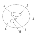
Fig. 3 is side view of an external transmitter unit and an external battery unit worn on the head of a patient. -
-
Fig. 1 is a side view of thehearing aid system 100 of the present invention. Askull bone 102 is visible since askin flap 104 has been folded away for the surgery. An implantedvibrator unit 106 is mounted in amastoid cavity 108. A mountingarm 110 extends from the implantedvibrator unit 106 to ananchoring fixture 112. Theanchoring fixture 112 is mounted through a hole (not seen) in the mountingarm 110. Theanchoring fixture 112 is screwed into theskull bone 102 from a lateral direction i.e. from the side of the skull. Avibrator supply cable 114 goes from the implanted vibrator unit to an implanted energy-receivingunit 116. The implanted energy-receivingunit 116 has an energy-receivinginductive coil 118 that can receive electromagnetic power by wireless induction from anexternal transmitter unit 120. The implantedelectronics 122 is placed in the implanted energy-receivingunit 116. The implanted energy-receivingunit 116 has amagnetic portion 124 so that theexternal transmitter unit 120 can be attached magnetically to the implanted energy-receivingunit 116. Before theexternal transmitter unit 120 is attached and used it is of course necessary to suture theskin flap 104 back over the implanted components and let the soft tissue heal. The implanted energy-receivingunit 116 is enclosed by asilicone protection 126. The implantedelectronics 122 can pick up the signal from a microphone (not seen) in theexternal transmitter unit 120. The implantedelectronics 122 is powered from the implanted energy-receivingunit 116. The implantedelectronics 122 amplifies the signal and drives the implantedvibrator unit 106. The vibrations from the implanted vibrator unit are transmitted to the skull bone via the mountingarm 110 and theanchoring fixture 112. -
Fig. 2 is a cross-sectional top view of an implantedvibrator unit 200. Avibrator 202 is enclosed by ahermetic housing 204. Thevibrator 202 has acoil 206, amagnet 208, anair gap 210, abobbin 212, aspring 214, avibration mass 216, abobbin frame 218 and avibrator plate 220. Thecoil 206, themagnet 208, thebobbin frame 218 and thebobbin 212 are fixated together and they are fixed in relation to thehousing 204. Thevibration mass 216 and thevibrator plate 220 are fixated together and they can oscillate in relation thehousing 204 to generate vibrations. Thespring 214 connects thevibrator plate 220 with thebobbin frame 218. A mountingarm 222 connects thehousing 204 of the implantedvibrator unit 200 with ananchoring fixture 224. Theanchoring fixture 224 has a threadedinner hole 226 to receive aconnection screw 228. Theconnection screw 228 goes through ahole 230 in the mountingarm 222 to fixate the mountingarm 222 to theanchoring fixture 224. The arrow (L) indicates the lateral direction. Theanchoring fixture 224 is screwed into theskull bone 231 from the lateral direction (L). The lateral direction points away from the head of the patient. Theanchoring fixture 224 has afixation portion 232 that is osseointegrated to theskull bone 231. The implantedvibrator unit 200 is positioned in themastoid cavity 234. -
Fig. 3 is side view of anexternal transmitter unit 302 and anexternal battery unit 304 worn on thehead 306 of a patient. Theexternal transmitter unit 302 is fixated to thehead 306 with a magnetic attachment to an implanted energy-receiving unit (not seen). Theexternal transmitter unit 302 is powered by theexternal battery unit 304 via acable 308. Theexternal battery unit 304 is worn on theouter ear 310.
Claims (13)
- A direct bone conduction hearing aid system, comprising:a microphone system for picking up audio sound and converting it into an electrical microphone signal;an amplifier (122) for amplifying the electrical microphone signal anddriving a vibrator (202) that generates audio vibrations;the vibrator being located in an implantable vibrator unit (106, 200) that has a hermetic housing (204) with a lateral end when it is in the implanted position;the vibrator being fixated to an internal side of the said lateral end of the housing when the implantable vibrator unit is positioned in a mastoid cavity;an anchoring fixture (112, 224) having a bone fixation portion that may be anchored in the skull bone through a lateral skull bone surface;a mounting arm (110, 222) being fixated at the said lateral end of the housing of the vibrator unit when it is in the implanted position;the mounting arm extending from the vibrator unit when it is in the implanted position to a lateral side of the skull bone over part of the skull bone surface where the mounting arm is fixated to the anchoring fixture in order to be fixated to the skull bone;whereby the vibrator when it is in the implanted position is mechanically connected to the skull bone via the housing of the vibrator unit, the mounting arm and the anchoring fixture;such that the audio vibrations from the vibrator go through the housing wall, the mounting arm and the anchoring fixture to the skull bone;an energy-receiving unit (116) adapted for implantation having an energy-receiving inductive coil (118) for picking up electromagnetic energy and converting it into an electric supply voltage and current;in order that the energy from the electric supply voltage and current may be used to supply the amplifier; anda vibrator supply cable (114) that goes from the energy-receiving unit to the implanted vibrator unit.
- The hearing aid system according to claim 1 wherein the vibrator is an electromagnetic vibrator where the coil of the vibrator is mechanically fixated in relation to the housing of the vibrator unit.
- The hearing aid system according to claim 1 wherein the hearing aid system has a battery.
- The hearing aid system according to claim 1 comprising:a transmitter unit;a battery in the transmitter unit;the microphone system being located in the transmitter unit; andthe transmitter unit having an energy-transmitting inductive coil adapted to transmit energy to the energy-receiving unit in its implanted state.
- The hearing aid system according to claim 1 comprising:a transmitter unit;a battery unit;a cord between the transmitter unit and the battery unit;the transmitter unit having an energy-transmitting inductive coil adapted to continuously transmits energy through the skin to the energy-receiving unit in its implanted state.
- The hearing aid system according to claim 1 comprising:a fixation screw to fixate the energy-receiving unit; anda hole in the energy-receiving unit to receive the fixation screw.
- The hearing aid system according to claim 1 wherein the vibrator supply cable has a connector so that the energy-receiving unit can be disconnected from the vibrator unit.
- The hearing aid system according to claim 1 wherein the anchoring fixture has a threaded inner hole to receive a connection screw that fixates the mounting arm to the anchoring fixture.
- The hearing aid system according to claim 1 wherein the electronics adapted for implantation includes an energy storing capacitor with a capacitance greater than 1 mF.
- The hearing aid system according to claim 1 wherein the vibrator unit, the mounting arm and the anchoring fixture is made in one unit.
- The hearing aid system according to claim 1 wherein the microphone system includes two microphones and a programmable microphone processing circuit where the sensitivity for sound intended to come from the front compared to sound intended to come from the rear is variable by programming the circuit digitally in a programmable circuit.
- The hearing aid system according to claim 1 wherein the system has a programmable circuit for digitally programming the sound processing parameters of the amplifier.
- The hearing aid system according to claim 1 wherein the hearing aid system has a digital feedback suppression circuit.
Applications Claiming Priority (2)
| Application Number | Priority Date | Filing Date | Title |
|---|---|---|---|
| US11/306,555 US7670278B2 (en) | 2006-01-02 | 2006-01-02 | Hearing aid system |
| PCT/US2006/046179 WO2007078506A2 (en) | 2006-01-02 | 2006-12-04 | Hearing aid system |
Publications (3)
| Publication Number | Publication Date |
|---|---|
| EP1972179A2 EP1972179A2 (en) | 2008-09-24 |
| EP1972179A4 EP1972179A4 (en) | 2012-05-09 |
| EP1972179B1 true EP1972179B1 (en) | 2014-11-12 |
Family
ID=38225430
Family Applications (1)
| Application Number | Title | Priority Date | Filing Date |
|---|---|---|---|
| EP06838891.7A Active EP1972179B1 (en) | 2006-01-02 | 2006-12-04 | Hearing aid system |
Country Status (6)
| Country | Link |
|---|---|
| US (1) | US7670278B2 (en) |
| EP (1) | EP1972179B1 (en) |
| CN (1) | CN101422051B (en) |
| AU (1) | AU2006333402B2 (en) |
| DK (1) | DK1972179T3 (en) |
| WO (1) | WO2007078506A2 (en) |
Cited By (1)
| Publication number | Priority date | Publication date | Assignee | Title |
|---|---|---|---|---|
| WO2026041967A1 (en) * | 2024-08-22 | 2026-02-26 | Cochlear Limited | Soft tissue fixation |
Families Citing this family (34)
| Publication number | Priority date | Publication date | Assignee | Title |
|---|---|---|---|---|
| US8246532B2 (en) | 2006-02-14 | 2012-08-21 | Vibrant Med-El Hearing Technology Gmbh | Bone conductive devices for improving hearing |
| US8469908B2 (en) * | 2007-04-06 | 2013-06-25 | Wilson T. Asfora | Analgesic implant device and system |
| US8512264B1 (en) * | 2007-04-06 | 2013-08-20 | Wilson T. Asfora | Analgesic implant device and system |
| SE0701242L (en) * | 2007-05-24 | 2008-12-02 | Cochlear Ltd | Vibrator |
| DK2083582T3 (en) * | 2008-01-28 | 2013-11-11 | Oticon Medical As | Bone conductive hearing aid with connection |
| SE533430C2 (en) * | 2008-02-20 | 2010-09-28 | Osseofon Ab | Implantable vibrator |
| US20090287038A1 (en) * | 2008-03-31 | 2009-11-19 | Cochlear Limited | Implanted-transducer bone conduction device |
| US8737649B2 (en) * | 2008-03-31 | 2014-05-27 | Cochlear Limited | Bone conduction device with a user interface |
| US8363871B2 (en) * | 2008-03-31 | 2013-01-29 | Cochlear Limited | Alternative mass arrangements for bone conduction devices |
| WO2010000027A1 (en) * | 2008-07-03 | 2010-01-07 | Cochlear Limited | Removable implantable battery positioned inside implant coil |
| EP2538700B1 (en) * | 2008-12-10 | 2013-11-13 | VIBRANT Med-El Hearing Technology GmbH | Skull vibration unit |
| USRE48797E1 (en) | 2009-03-25 | 2021-10-26 | Cochlear Limited | Bone conduction device having a multilayer piezoelectric element |
| DE102009014774A1 (en) * | 2009-03-25 | 2010-09-30 | Cochlear Ltd., Lane Cove | hearing aid |
| DE102009014770A1 (en) | 2009-03-25 | 2010-09-30 | Cochlear Ltd., Lane Cove | vibrator |
| US8965021B2 (en) | 2009-06-09 | 2015-02-24 | Dalhousie University | Subcutaneous piezoelectric bone conduction hearing aid actuator and system |
| WO2010142018A1 (en) | 2009-06-09 | 2010-12-16 | Dalhousie University | Subcutaneous piezoelectric bone conduction hearing aid actuator and system |
| US8594356B2 (en) * | 2010-04-29 | 2013-11-26 | Cochlear Limited | Bone conduction device having limited range of travel |
| CA2798874C (en) | 2010-05-10 | 2018-01-02 | Dalhousie University | Phenolic compositions derived from apple skin and uses thereof |
| US9107013B2 (en) | 2011-04-01 | 2015-08-11 | Cochlear Limited | Hearing prosthesis with a piezoelectric actuator |
| EP2592848B1 (en) * | 2011-11-08 | 2019-06-26 | Oticon Medical A/S | Acoustic transmission method and listening device. |
| CN102908227A (en) * | 2012-11-16 | 2013-02-06 | 上海力声特医学科技有限公司 | Artificial cochlea implanting device with fixing members |
| US10003898B1 (en) * | 2013-02-15 | 2018-06-19 | Cochlear Limited | Flexible connection bone conduction device |
| EP2897378B1 (en) * | 2014-01-21 | 2020-08-19 | Oticon Medical A/S | Hearing aid device using dual electromechanical vibrator |
| CN112822620A (en) * | 2014-05-27 | 2021-05-18 | 索飞诺股份有限公司 | Systems, devices, components, and methods for reducing feedback between a microphone and a transducer in a bone conduction magnetic hearing assistance device |
| CN104936096B (en) | 2015-05-29 | 2018-07-17 | 京东方科技集团股份有限公司 | Bone conduction sound propagation device and method |
| GB201509283D0 (en) | 2015-05-29 | 2015-07-15 | Sonic Hearing Ltd | Hearing aid |
| CN106236104A (en) * | 2016-07-22 | 2016-12-21 | 南方科技大学 | Hearing test device |
| DK3306955T3 (en) | 2016-10-10 | 2019-08-19 | Oticon Medical As | HEARING INCLUDING AN AUTOMATIC SWITCH |
| US11432084B2 (en) * | 2016-10-28 | 2022-08-30 | Cochlear Limited | Passive integrity management of an implantable device |
| US10327974B2 (en) * | 2017-08-02 | 2019-06-25 | Immersion Corporation | Haptic implants |
| EP3441111B1 (en) | 2017-08-11 | 2020-09-09 | Oticon Medical A/S | Implantable medical device comprising a wireless transcutaneous link |
| EP3780654B1 (en) * | 2019-08-15 | 2025-05-14 | Oticon Medical A/S | Transcutaneous bone-anchored hearing aid with reduced thickness |
| EP4167597A1 (en) * | 2021-10-14 | 2023-04-19 | Oticon Medical A/S | An electromagnetic vibrator for generating a vibration in order to transmit sound through a bone of a skull of a user to an ear of the user and a bone anchored hearing device |
| WO2024256925A1 (en) * | 2023-06-12 | 2024-12-19 | Cochlear Limited | Asymmetric bone conduction device |
Family Cites Families (11)
| Publication number | Priority date | Publication date | Assignee | Title |
|---|---|---|---|---|
| US4612915A (en) * | 1985-05-23 | 1986-09-23 | Xomed, Inc. | Direct bone conduction hearing aid device |
| CN2034442U (en) * | 1987-05-13 | 1989-03-22 | 龚鹓文 | Double-guiding type hearing aid series for deaf-mute |
| US5015224A (en) * | 1988-10-17 | 1991-05-14 | Maniglia Anthony J | Partially implantable hearing aid device |
| CN2261828Y (en) * | 1996-04-22 | 1997-09-10 | 上海医科大学附属眼耳鼻喉科医院 | Multi-path program controlled artificial cochlea |
| DE10018334C1 (en) * | 2000-04-13 | 2002-02-28 | Implex Hear Tech Ag | At least partially implantable system for the rehabilitation of a hearing impairment |
| SE523123C2 (en) * | 2000-06-02 | 2004-03-30 | P & B Res Ab | Hearing aid that works with the principle of bone conduction |
| DE10047388C1 (en) * | 2000-09-25 | 2002-01-10 | Implex Hear Tech Ag | Implantable hearing system, includes a detachable coupling for securing and locating a transducer and a micro-manipulator |
| US6829364B2 (en) * | 2001-06-22 | 2004-12-07 | Topholm & Westermann Aps, Ny | Hearing aid with a capacitor having a large capacitance |
| FR2841429B1 (en) * | 2002-06-21 | 2005-11-11 | Mxm | HEARING AID DEVICE FOR THE REHABILITATION OF PATIENTS WITH PARTIAL NEUROSENSORY DEATHS |
| CN1401395A (en) * | 2002-09-09 | 2003-03-12 | 复旦大学附属华山医院 | Piezoelectric artificial cochlea |
| US7033313B2 (en) * | 2002-12-11 | 2006-04-25 | No. 182 Corporate Ventures Ltd. | Surgically implantable hearing aid |
-
2006
- 2006-01-02 US US11/306,555 patent/US7670278B2/en active Active
- 2006-12-04 EP EP06838891.7A patent/EP1972179B1/en active Active
- 2006-12-04 CN CN200680050317XA patent/CN101422051B/en active Active
- 2006-12-04 AU AU2006333402A patent/AU2006333402B2/en active Active
- 2006-12-04 DK DK06838891.7T patent/DK1972179T3/en active
- 2006-12-04 WO PCT/US2006/046179 patent/WO2007078506A2/en not_active Ceased
Cited By (1)
| Publication number | Priority date | Publication date | Assignee | Title |
|---|---|---|---|---|
| WO2026041967A1 (en) * | 2024-08-22 | 2026-02-26 | Cochlear Limited | Soft tissue fixation |
Also Published As
| Publication number | Publication date |
|---|---|
| AU2006333402B2 (en) | 2010-08-19 |
| US7670278B2 (en) | 2010-03-02 |
| DK1972179T3 (en) | 2015-02-09 |
| WO2007078506A2 (en) | 2007-07-12 |
| AU2006333402A1 (en) | 2007-07-12 |
| WO2007078506A3 (en) | 2008-12-24 |
| CN101422051A (en) | 2009-04-29 |
| CN101422051B (en) | 2012-07-04 |
| EP1972179A2 (en) | 2008-09-24 |
| US20070156011A1 (en) | 2007-07-05 |
| EP1972179A4 (en) | 2012-05-09 |
Similar Documents
| Publication | Publication Date | Title |
|---|---|---|
| US7670278B2 (en) | Hearing aid system | |
| US20070053536A1 (en) | Hearing aid system | |
| AU2015200232B2 (en) | Hearing Aid Device Using Dual Electromechanical Vibrator | |
| US6084975A (en) | Promontory transmitting coil and tympanic membrane magnet for hearing devices | |
| EP2592848B1 (en) | Acoustic transmission method and listening device. | |
| US20040032962A1 (en) | Bone conducting hearing aid | |
| EP2600796B1 (en) | Implantable piezoelectric polymer film microphone | |
| US20110319703A1 (en) | Implantable Microphone System and Calibration Process | |
| EP1483937A1 (en) | Hearing aid apparatus | |
| AU2003291875A1 (en) | Surgically implantable hearing aid | |
| US20220323757A1 (en) | Implantable battery device for standard cochlear implant | |
| WO2010133702A2 (en) | Partially implantable hearing instrument | |
| US20130172662A1 (en) | Partially implantable hearing assistance system | |
| US9179226B2 (en) | Partially implantable hearing device | |
| US20240136858A1 (en) | Electromagnetic transducer charging |
Legal Events
| Date | Code | Title | Description |
|---|---|---|---|
| PUAI | Public reference made under article 153(3) epc to a published international application that has entered the european phase |
Free format text: ORIGINAL CODE: 0009012 |
|
| AK | Designated contracting states |
Kind code of ref document: A2 Designated state(s): AT BE BG CH CY CZ DE DK EE ES FI FR GB GR HU IE IS IT LI LT LU LV MC NL PL PT RO SE SI SK TR |
|
| AX | Request for extension of the european patent |
Extension state: AL BA HR MK RS |
|
| R17D | Deferred search report published (corrected) |
Effective date: 20081224 |
|
| 17P | Request for examination filed |
Effective date: 20090624 |
|
| RBV | Designated contracting states (corrected) |
Designated state(s): AT BE BG CH CY CZ DE DK EE ES FI FR GB GR HU IE IS IT LI LT LU LV MC NL PL PT RO SE SI SK TR |
|
| A4 | Supplementary search report drawn up and despatched |
Effective date: 20120410 |
|
| RIC1 | Information provided on ipc code assigned before grant |
Ipc: H04R 25/00 20060101AFI20120402BHEP |
|
| RAP1 | Party data changed (applicant data changed or rights of an application transferred) |
Owner name: OTICON MEDICAL A/S |
|
| DAX | Request for extension of the european patent (deleted) | ||
| GRAP | Despatch of communication of intention to grant a patent |
Free format text: ORIGINAL CODE: EPIDOSNIGR1 |
|
| INTG | Intention to grant announced |
Effective date: 20140226 |
|
| GRAP | Despatch of communication of intention to grant a patent |
Free format text: ORIGINAL CODE: EPIDOSNIGR1 |
|
| INTG | Intention to grant announced |
Effective date: 20140603 |
|
| GRAS | Grant fee paid |
Free format text: ORIGINAL CODE: EPIDOSNIGR3 |
|
| GRAA | (expected) grant |
Free format text: ORIGINAL CODE: 0009210 |
|
| AK | Designated contracting states |
Kind code of ref document: B1 Designated state(s): AT BE BG CH CY CZ DE DK EE ES FI FR GB GR HU IE IS IT LI LT LU LV MC NL PL PT RO SE SI SK TR |
|
| REG | Reference to a national code |
Ref country code: GB Ref legal event code: FG4D |
|
| REG | Reference to a national code |
Ref country code: CH Ref legal event code: EP |
|
| REG | Reference to a national code |
Ref country code: AT Ref legal event code: REF Ref document number: 696381 Country of ref document: AT Kind code of ref document: T Effective date: 20141115 |
|
| REG | Reference to a national code |
Ref country code: IE Ref legal event code: FG4D |
|
| REG | Reference to a national code |
Ref country code: DE Ref legal event code: R096 Ref document number: 602006043673 Country of ref document: DE Effective date: 20141224 |
|
| REG | Reference to a national code |
Ref country code: DK Ref legal event code: T3 Effective date: 20150205 |
|
| REG | Reference to a national code |
Ref country code: SE Ref legal event code: TRGR |
|
| REG | Reference to a national code |
Ref country code: NL Ref legal event code: VDEP Effective date: 20141112 |
|
| PG25 | Lapsed in a contracting state [announced via postgrant information from national office to epo] |
Ref country code: NL Free format text: LAPSE BECAUSE OF FAILURE TO SUBMIT A TRANSLATION OF THE DESCRIPTION OR TO PAY THE FEE WITHIN THE PRESCRIBED TIME-LIMIT Effective date: 20141112 Ref country code: IS Free format text: LAPSE BECAUSE OF FAILURE TO SUBMIT A TRANSLATION OF THE DESCRIPTION OR TO PAY THE FEE WITHIN THE PRESCRIBED TIME-LIMIT Effective date: 20150312 Ref country code: ES Free format text: LAPSE BECAUSE OF FAILURE TO SUBMIT A TRANSLATION OF THE DESCRIPTION OR TO PAY THE FEE WITHIN THE PRESCRIBED TIME-LIMIT Effective date: 20141112 Ref country code: PT Free format text: LAPSE BECAUSE OF FAILURE TO SUBMIT A TRANSLATION OF THE DESCRIPTION OR TO PAY THE FEE WITHIN THE PRESCRIBED TIME-LIMIT Effective date: 20150312 Ref country code: FI Free format text: LAPSE BECAUSE OF FAILURE TO SUBMIT A TRANSLATION OF THE DESCRIPTION OR TO PAY THE FEE WITHIN THE PRESCRIBED TIME-LIMIT Effective date: 20141112 Ref country code: LT Free format text: LAPSE BECAUSE OF FAILURE TO SUBMIT A TRANSLATION OF THE DESCRIPTION OR TO PAY THE FEE WITHIN THE PRESCRIBED TIME-LIMIT Effective date: 20141112 |
|
| PG25 | Lapsed in a contracting state [announced via postgrant information from national office to epo] |
Ref country code: CY Free format text: LAPSE BECAUSE OF FAILURE TO SUBMIT A TRANSLATION OF THE DESCRIPTION OR TO PAY THE FEE WITHIN THE PRESCRIBED TIME-LIMIT Effective date: 20141112 Ref country code: LV Free format text: LAPSE BECAUSE OF FAILURE TO SUBMIT A TRANSLATION OF THE DESCRIPTION OR TO PAY THE FEE WITHIN THE PRESCRIBED TIME-LIMIT Effective date: 20141112 Ref country code: PL Free format text: LAPSE BECAUSE OF FAILURE TO SUBMIT A TRANSLATION OF THE DESCRIPTION OR TO PAY THE FEE WITHIN THE PRESCRIBED TIME-LIMIT Effective date: 20141112 Ref country code: GR Free format text: LAPSE BECAUSE OF FAILURE TO SUBMIT A TRANSLATION OF THE DESCRIPTION OR TO PAY THE FEE WITHIN THE PRESCRIBED TIME-LIMIT Effective date: 20150213 |
|
| PG25 | Lapsed in a contracting state [announced via postgrant information from national office to epo] |
Ref country code: BE Free format text: LAPSE BECAUSE OF NON-PAYMENT OF DUE FEES Effective date: 20141231 |
|
| PG25 | Lapsed in a contracting state [announced via postgrant information from national office to epo] |
Ref country code: RO Free format text: LAPSE BECAUSE OF FAILURE TO SUBMIT A TRANSLATION OF THE DESCRIPTION OR TO PAY THE FEE WITHIN THE PRESCRIBED TIME-LIMIT Effective date: 20141112 Ref country code: EE Free format text: LAPSE BECAUSE OF FAILURE TO SUBMIT A TRANSLATION OF THE DESCRIPTION OR TO PAY THE FEE WITHIN THE PRESCRIBED TIME-LIMIT Effective date: 20141112 Ref country code: CZ Free format text: LAPSE BECAUSE OF FAILURE TO SUBMIT A TRANSLATION OF THE DESCRIPTION OR TO PAY THE FEE WITHIN THE PRESCRIBED TIME-LIMIT Effective date: 20141112 Ref country code: SK Free format text: LAPSE BECAUSE OF FAILURE TO SUBMIT A TRANSLATION OF THE DESCRIPTION OR TO PAY THE FEE WITHIN THE PRESCRIBED TIME-LIMIT Effective date: 20141112 |
|
| REG | Reference to a national code |
Ref country code: DE Ref legal event code: R097 Ref document number: 602006043673 Country of ref document: DE |
|
| PG25 | Lapsed in a contracting state [announced via postgrant information from national office to epo] |
Ref country code: MC Free format text: LAPSE BECAUSE OF FAILURE TO SUBMIT A TRANSLATION OF THE DESCRIPTION OR TO PAY THE FEE WITHIN THE PRESCRIBED TIME-LIMIT Effective date: 20141112 |
|
| PLBE | No opposition filed within time limit |
Free format text: ORIGINAL CODE: 0009261 |
|
| STAA | Information on the status of an ep patent application or granted ep patent |
Free format text: STATUS: NO OPPOSITION FILED WITHIN TIME LIMIT |
|
| REG | Reference to a national code |
Ref country code: IE Ref legal event code: MM4A |
|
| 26N | No opposition filed |
Effective date: 20150813 |
|
| PG25 | Lapsed in a contracting state [announced via postgrant information from national office to epo] |
Ref country code: IE Free format text: LAPSE BECAUSE OF NON-PAYMENT OF DUE FEES Effective date: 20141204 |
|
| PG25 | Lapsed in a contracting state [announced via postgrant information from national office to epo] |
Ref country code: IT Free format text: LAPSE BECAUSE OF FAILURE TO SUBMIT A TRANSLATION OF THE DESCRIPTION OR TO PAY THE FEE WITHIN THE PRESCRIBED TIME-LIMIT Effective date: 20141112 |
|
| REG | Reference to a national code |
Ref country code: FR Ref legal event code: PLFP Year of fee payment: 10 |
|
| REG | Reference to a national code |
Ref country code: AT Ref legal event code: UEP Ref document number: 696381 Country of ref document: AT Kind code of ref document: T Effective date: 20141112 |
|
| PG25 | Lapsed in a contracting state [announced via postgrant information from national office to epo] |
Ref country code: SI Free format text: LAPSE BECAUSE OF FAILURE TO SUBMIT A TRANSLATION OF THE DESCRIPTION OR TO PAY THE FEE WITHIN THE PRESCRIBED TIME-LIMIT Effective date: 20141112 |
|
| PG25 | Lapsed in a contracting state [announced via postgrant information from national office to epo] |
Ref country code: BG Free format text: LAPSE BECAUSE OF FAILURE TO SUBMIT A TRANSLATION OF THE DESCRIPTION OR TO PAY THE FEE WITHIN THE PRESCRIBED TIME-LIMIT Effective date: 20141112 |
|
| PG25 | Lapsed in a contracting state [announced via postgrant information from national office to epo] |
Ref country code: HU Free format text: LAPSE BECAUSE OF FAILURE TO SUBMIT A TRANSLATION OF THE DESCRIPTION OR TO PAY THE FEE WITHIN THE PRESCRIBED TIME-LIMIT; INVALID AB INITIO Effective date: 20061204 Ref country code: LU Free format text: LAPSE BECAUSE OF NON-PAYMENT OF DUE FEES Effective date: 20141204 Ref country code: TR Free format text: LAPSE BECAUSE OF FAILURE TO SUBMIT A TRANSLATION OF THE DESCRIPTION OR TO PAY THE FEE WITHIN THE PRESCRIBED TIME-LIMIT Effective date: 20141112 |
|
| REG | Reference to a national code |
Ref country code: FR Ref legal event code: PLFP Year of fee payment: 11 |
|
| REG | Reference to a national code |
Ref country code: FR Ref legal event code: PLFP Year of fee payment: 12 |
|
| REG | Reference to a national code |
Ref country code: CH Ref legal event code: U11 Free format text: ST27 STATUS EVENT CODE: U-0-0-U10-U11 (AS PROVIDED BY THE NATIONAL OFFICE) Effective date: 20260101 |
|
| PGFP | Annual fee paid to national office [announced via postgrant information from national office to epo] |
Ref country code: DE Payment date: 20251125 Year of fee payment: 20 |
|
| PGFP | Annual fee paid to national office [announced via postgrant information from national office to epo] |
Ref country code: GB Payment date: 20251125 Year of fee payment: 20 |
|
| PGFP | Annual fee paid to national office [announced via postgrant information from national office to epo] |
Ref country code: AT Payment date: 20251125 Year of fee payment: 20 |
|
| PGFP | Annual fee paid to national office [announced via postgrant information from national office to epo] |
Ref country code: DK Payment date: 20251125 Year of fee payment: 20 |
|
| PGFP | Annual fee paid to national office [announced via postgrant information from national office to epo] |
Ref country code: FR Payment date: 20251125 Year of fee payment: 20 |
|
| PGFP | Annual fee paid to national office [announced via postgrant information from national office to epo] |
Ref country code: SE Payment date: 20251125 Year of fee payment: 20 |
|
| PGFP | Annual fee paid to national office [announced via postgrant information from national office to epo] |
Ref country code: CH Payment date: 20260101 Year of fee payment: 20 |