EP1972087B1 - Symmetric transmit opportunity (txop) truncation - Google Patents
Symmetric transmit opportunity (txop) truncation Download PDFInfo
- Publication number
- EP1972087B1 EP1972087B1 EP07710033.7A EP07710033A EP1972087B1 EP 1972087 B1 EP1972087 B1 EP 1972087B1 EP 07710033 A EP07710033 A EP 07710033A EP 1972087 B1 EP1972087 B1 EP 1972087B1
- Authority
- EP
- European Patent Office
- Prior art keywords
- frame
- station
- sending
- receiving
- txop
- Prior art date
- Legal status (The legal status is an assumption and is not a legal conclusion. Google has not performed a legal analysis and makes no representation as to the accuracy of the status listed.)
- Active
Links
- 238000000034 method Methods 0.000 claims description 96
- 230000005540 biological transmission Effects 0.000 claims description 21
- 230000004044 response Effects 0.000 claims description 16
- 230000007246 mechanism Effects 0.000 description 45
- 238000004891 communication Methods 0.000 description 21
- 238000010586 diagram Methods 0.000 description 21
- OVGWMUWIRHGGJP-WVDJAODQSA-N (z)-7-[(1s,3r,4r,5s)-3-[(e,3r)-3-hydroxyoct-1-enyl]-6-thiabicyclo[3.1.1]heptan-4-yl]hept-5-enoic acid Chemical compound OC(=O)CCC\C=C/C[C@@H]1[C@@H](/C=C/[C@H](O)CCCCC)C[C@@H]2S[C@H]1C2 OVGWMUWIRHGGJP-WVDJAODQSA-N 0.000 description 9
- 101000988961 Escherichia coli Heat-stable enterotoxin A2 Proteins 0.000 description 9
- 230000008569 process Effects 0.000 description 6
- 230000006870 function Effects 0.000 description 4
- 101000752249 Homo sapiens Rho guanine nucleotide exchange factor 3 Proteins 0.000 description 2
- 102100021689 Rho guanine nucleotide exchange factor 3 Human genes 0.000 description 2
- 230000001413 cellular effect Effects 0.000 description 2
- 238000012986 modification Methods 0.000 description 2
- 230000004048 modification Effects 0.000 description 2
- OVGWMUWIRHGGJP-WTODYLRWSA-N (z)-7-[(1r,3s,4s,5r)-3-[(e,3r)-3-hydroxyoct-1-enyl]-6-thiabicyclo[3.1.1]heptan-4-yl]hept-5-enoic acid Chemical compound OC(=O)CCC\C=C/C[C@H]1[C@H](/C=C/[C@H](O)CCCCC)C[C@H]2S[C@@H]1C2 OVGWMUWIRHGGJP-WTODYLRWSA-N 0.000 description 1
- 101100366889 Caenorhabditis elegans sta-2 gene Proteins 0.000 description 1
- 101100172132 Mus musculus Eif3a gene Proteins 0.000 description 1
- 230000001934 delay Effects 0.000 description 1
- 230000001419 dependent effect Effects 0.000 description 1
- 230000004069 differentiation Effects 0.000 description 1
- 230000000694 effects Effects 0.000 description 1
- 238000005516 engineering process Methods 0.000 description 1
- 230000006855 networking Effects 0.000 description 1
- 239000000523 sample Substances 0.000 description 1
Images


Classifications
-
- H—ELECTRICITY
- H04—ELECTRIC COMMUNICATION TECHNIQUE
- H04W—WIRELESS COMMUNICATION NETWORKS
- H04W74/00—Wireless channel access
- H04W74/08—Non-scheduled access, e.g. ALOHA
- H04W74/0808—Non-scheduled access, e.g. ALOHA using carrier sensing, e.g. carrier sense multiple access [CSMA]
- H04W74/0816—Non-scheduled access, e.g. ALOHA using carrier sensing, e.g. carrier sense multiple access [CSMA] with collision avoidance
-
- H—ELECTRICITY
- H04—ELECTRIC COMMUNICATION TECHNIQUE
- H04L—TRANSMISSION OF DIGITAL INFORMATION, e.g. TELEGRAPHIC COMMUNICATION
- H04L12/00—Data switching networks
- H04L12/28—Data switching networks characterised by path configuration, e.g. LAN [Local Area Networks] or WAN [Wide Area Networks]
- H04L12/40—Bus networks
- H04L12/407—Bus networks with decentralised control
- H04L12/413—Bus networks with decentralised control with random access, e.g. carrier-sense multiple-access with collision detection [CSMA-CD]
-
- H—ELECTRICITY
- H04—ELECTRIC COMMUNICATION TECHNIQUE
- H04J—MULTIPLEX COMMUNICATION
- H04J1/00—Frequency-division multiplex systems
- H04J1/02—Details
- H04J1/16—Monitoring arrangements
-
- H—ELECTRICITY
- H04—ELECTRIC COMMUNICATION TECHNIQUE
- H04W—WIRELESS COMMUNICATION NETWORKS
- H04W74/00—Wireless channel access
- H04W74/002—Transmission of channel access control information
- H04W74/006—Transmission of channel access control information in the downlink, i.e. towards the terminal
-
- H—ELECTRICITY
- H04—ELECTRIC COMMUNICATION TECHNIQUE
- H04W—WIRELESS COMMUNICATION NETWORKS
- H04W74/00—Wireless channel access
- H04W74/04—Scheduled access
-
- H—ELECTRICITY
- H04—ELECTRIC COMMUNICATION TECHNIQUE
- H04W—WIRELESS COMMUNICATION NETWORKS
- H04W84/00—Network topologies
- H04W84/02—Hierarchically pre-organised networks, e.g. paging networks, cellular networks, WLAN [Wireless Local Area Network] or WLL [Wireless Local Loop]
- H04W84/10—Small scale networks; Flat hierarchical networks
- H04W84/12—WLAN [Wireless Local Area Networks]
Definitions
- the present disclosure is generally related to communication systems and methods and, more particularly, is related to collision avoidance systems and methods in wireless networks.
- Notable networks include wireline and wireless.
- Wireline networks include local area networks (LANs), DSL networks, and cable networks, among others.
- Wireless networks include cellular telephone networks, classic land mobile radio networks and satellite transmission networks, among others. These wireless networks are typically characterized as wide area networks. More recently, wireless local area networks and wireless home networks have been proposed, and standards, such as Bluetooth and IEEE 802.11, have been introduced to govern the development of wireless equipment for such localized networks.
- a wireless local area network typically uses infrared (IR) or radio frequency (RF) communication channels to communicate between portable or mobile computer terminals and access points (APs) or base stations. These APs are, in turn, connected by a wired or wireless communications channel to a network infrastructure which connects groups of access points together to form the LAN, including, optionally, one or more host computer systems.
- IR infrared
- RF radio frequency
- Wireless protocols such as Bluetooth and IEEE 802.11 support the logical interconnections of such portable roaming terminals having a variety of types of communication capabilities to host computers.
- the logical interconnections are based upon an infrastructure in which at least some of the terminals are capable of communicating with at least two of the APs when located within a predetermined range, each terminal being normally associated, and in communication, with a single one of the access points.
- IEEE Standard 802.11 (“802.11") is set out in "Wireless LAN Medium Access Control (MAC) and Physical Layer (PHY) Specifications” and is available from the IEEE Standards Department, Piscataway, N.J.
- the IEEE 802.11 standard permits either IR or RF communications at 1 Mbps, 2 Mbps and higher data rates, a medium access technique similar to carrier sense multiple access/collision avoidance (CSMA/CA), a power-save mode for battery-operated mobile stations, seamless roaming in a full cellular network, high throughput operation, diverse antenna systems designed to eliminate "dead spots," and an easy interface to existing network infrastructures.
- the IEEE Standard 802.11b extension supports data rates up to 11 Mbps.
- the current 802.11 standard describes several methods to set a virtual carrier sense, referred to as a network allocation vector or NAV, most notably by request to send/clear to send (RTS/CTS) mechanisms.
- RTS frame also referred to as, simply, RTS
- CTS frame is also referred to as CTS
- CTS does the same locally around the sender of the CTS (e.g ., the receiver of the RTS).
- a hidden node problem For instance, in an infrastructure mode of a wireless LAN system, a first device may communicate frames to the AP and vice versa. Similarly, a second device may communicate frames to the AP, and vice versa. However, the second device may not detect transmissions from the first device (hence the phrase hidden node), for instance if the distance between the first and second device is too great. Because of the hidden node problem, various complications may arise in terms of collision avoidance and symmetry of response among devices, causing inequity in terms of opportunities for access to a shared medium of the communication system.
- the NAV can be reset by an access point (AP) through the transmission of what is commonly referred to as a CF-end frame.
- a CF-end frame 10 is shown in FIG. 1 , and comprises two octets (exemplary quantity of octets shown beneath the frame 10) corresponding to a frame control field 102, two octets corresponding to duration field 104, six octets corresponding to a receiver address (RA) field 106, which usually contains the Broadcast Address (BC), six octets corresponding to a basic service set identifier (BSSID) field 108, and four octets corresponding to a frame check sequence (FCS) field 110.
- BC Broadcast Address
- BSSID basic service set identifier
- FCS frame check sequence
- WO 2005/039105 discloses high speed media access control and direct link protocol.
- Embodiments of the present disclosure provide symmetric transmit opportunity (TXOP) truncation systems and methods in a wireless network. Briefly described, one embodiment of a method, among others, comprises receiving a frame that truncates a TXOP around a first station, and responsive to receiving the frame, sending a second frame that truncates the TXOP around a second station.
- TXOP transmit opportunity
- Another method embodiment comprises receiving a frame from an access point (AP) that includes an indicator of an end of a TXOP, responsive to receiving the indicator, sending a first frame that truncates the TXOP around a first station, receiving the first frame at the AP, and responsive to receiving the first frame at the AP, sending a second frame that truncates the TXOP around the AP.
- AP access point
- Another method embodiment comprises sending at a first station a first frame, sending at the first station an extended interframe space (EIFS) set frame after the first frame, and sending at a second station a second frame having a completed transmission corresponding to time based on an interval of EIFS less DIFS, the interval commencing from an end of the short frame.
- EIFS extended interframe space
- One system embodiment comprises a processor configured with logic to receive a frame that truncates a TXOP around a first station and, responsive to receiving the frame, the processor further configured with the logic to send a second frame that truncates the TXOP around a second station.
- Another system embodiment comprises means for receiving a frame that truncates a TXOP around a first station, and responsive to receiving the frame, means for sending a second frame that truncates the TXOP around a second station.
- TXOP transmit opportunity
- STT symmetric transmit opportunity truncation
- the STT systems described herein comprise functionality to truncate a TXOP in a symmetric manner in a plurality of devices. That is, in various STT systems and methods described herein, both access points (APs) and client stations (herein, clients) are also allowed to truncate their TXOPs by transmitting a CF-end frame.
- APs access points
- client stations herein, clients
- a TXOP truncation is referred to as a TXOP truncation, where a NAV is first set for some maximum duration of time (e.g ., the TXOP limit) and then reset when no more traffic (e.g ., of frames) is left and there is some NAV time that still remains.
- a TXOP comprises a signal exchange which may begin with the transmission of a short frame such as an RTS or CTS and ends with the last frame sent or received by the sender of the short frame (e.g ., sender of the RTS or CTS).
- the truncation at both clients and APs resolve the various problems resulting from a reset that is not symmetrical, such as in conventional systems where the reset comes from a single device (though set by both devices through the RTS/CTS mechanisms).
- Various embodiments of the STT systems provide one or more mechanisms for the symmetrical truncation of TXOPs.
- the various embodiments of the STT systems described herein may similarly be applied to other systems and environments, such as ad hoc systems (e.g., independent BSS (IBSS) systems) or DLC systems, as well as other communication system environments.
- IBSS independent BSS
- IEEE 802.11 is prominently used herein as an example of a standard used in the disclosed exemplary wireless networks, the various systems and methods described herein may apply to virtually any wireless network.
- some embodiments of the STT systems may include some or all of the functionality of collision avoidance systems (CA systems) described in the co-pending application having serial number 11/557,516 and incorporated herein by reference in its entirety.
- CA systems collision avoidance systems
- FIG. 2 shows an exemplary wireless LAN (WLAN) environment 100 in which various embodiments of a symmetric transmit opportunity (TXOP) truncation (STT) system 200 may be implemented.
- the STT system 200 is configured as a basic service set (BSS), which comprises a plurality of stations or nodes, such as stations 202, 204, and 206.
- BSS basic service set
- Each of the stations 202, 204, and 206 may be embodied as one of many wireless communication devices, including computers (desktop, portable, laptop, etc.), consumer electronic devices (e.g., multi-media players), compatible telecommunication devices, personal digital assistants (PDAs), or any other type of network devices such as printers, fax machines, scanners, hubs, switches, routers, set-top boxes, televisions with communication capability, etc.
- computers desktop, portable, laptop, etc.
- consumer electronic devices e.g., multi-media players
- compatible telecommunication devices e.g., personal digital assistants (PDAs)
- PDAs personal digital assistants
- any other type of network devices such as printers, fax machines, scanners, hubs, switches, routers, set-top boxes, televisions with communication capability, etc.
- the STT system 200 shown in FIG. 2 comprises, in one embodiment, an access point (AP) station 202 (herein, also referred to, simply, as an AP) and one or more client stations 204, 206 (herein, also referred to individually or collectively as client(s)).
- the STT system 200 is configured in what may be referred to as an infrastructure mode, whereby clients 204 and 206 communicate frames directly with the AP 202 and not with each other.
- the various embodiments of STT systems 200 are not limited to such arrangements, and in some embodiments, may be arranged in ad hoc or direct link communication configurations.
- Included within each of the AP 202 and clients 204, 206 is control logic 300.
- the control logic 300 implements MAC layer and PHY layer services.
- the MAC layer services provide the capability for a given station to exchange MAC frames.
- the MAC layer services provide management, control, or data frames for transmission between stations 202, 204, and 206.
- the 802.11 MAC layer services make use of at least three frame types (data, management, control), and within each type, various subtypes. For instance, request-to-send (RTS) frames, clear-to-send (CTS) frames, and CF-end frames are examples of control subtypes (e.g., control/CF-end refers to a control-type frame of the subtype, CF-end).
- RTS request-to-send
- CTS clear-to-send
- CF-end frames are examples of control subtypes (e.g., control/CF-end refers to a control-type frame of the subtype, CF-end).
- the frame bits are passed to the PHY layer for transmission.
- the control logic 300 can be configured using a plurality of modules (e.g .
- control logic 300 can be implemented in hardware, software, or a combination thereof. When implemented in whole or in part by software, control logic 300 is implemented in software stored in a memory that is executed by a suitable instruction execution system. When implemented in whole or in part by hardware, the control logic 300 can be implemented with any or a combination of the following technologies, which are all well known in the art: a discrete logic circuit(s) having logic gates for implementing logic functions upon data signals, an application specific integrated circuit (ASIC) having appropriate combinational logic gates, a programmable gate array(s) (PGA), a field programmable gate array (FPGA), etc.
- ASIC application specific integrated circuit
- PGA programmable gate array
- FPGA field programmable gate array
- control logic 300 may include a PHY layer processor, MAC layer processor, or a combination of both (in the same or separate units), including, but not limited to, a digital signal processor (DSP), a microprocessor unit (MCU), a general purpose processor, and an application specific integrated circuit (ASIC), among others.
- DSP digital signal processor
- MCU microprocessor unit
- ASIC application specific integrated circuit
- the AP 202 is typically connected to a wired network (e.g., Ethernet), not shown.
- the clients such as client 204, connect to the AP 202 through a scanning process.
- the scanning process can either be performed passively by listening for a beacon transmitted by one or more APs 202, or actively by sending out probes to one or more APs 202 and choosing an AP that provides the best connection (e.g., in terms of signal strength and/or bit error ratio (BER)).
- BER bit error ratio
- association involves the communication between the clients 204, 206 and the AP 202 via a shared wireless medium 208.
- the client 206 may represent a hidden node to client 204, and vice versa.
- FIGS. 3A-16 Various mechanisms or methods for signal exchanges are illustrated in FIGS. 3A-16 to highlight various features of embodiments of the STT system 200. Although described below in the context of the AP 202 or client 204 (or similarly client 206) sending or receiving various transmissions, it can be understood in the context of this disclosure that the effectuating of the various functionality of the STT system 200 is through the control logic 300 of each station (node).
- interframe spaces e.g ., extended interframe space (EIFS), short interframe space (SIFS), etc.
- EIFS extended interframe space
- SIFS short interframe space
- FIGS. 3A-3B show one mechanism used by an embodiment of the STT system 200 to set a NAV and/or avoid EIFS for an AP-initiated TXOP.
- the AP 202 sets a NAV prior to a TXOP 302 by starting the TXOP 302 with a short frame 304 (e.g., short to reduce the probability of error) at a low basic rate.
- blocks 302 and 304 collectively comprise a TXOP.
- the short frame 304 contains a duration value (e.g., the NAV setting) equal to the expected length of the TXOP 302.
- the AP 202 avoids any EIFS at the end of the TXOP 302 by sending a short frame 306 (typically containing a duration value of zero) at a low basic rate as the final frame of the TXOP 302.
- blocks 302 and 306 collectively comprise a TXOP. In each case, the rate is selected such that frames from the AP 202 reach all nodes in the network (e.g., BSS).
- FIGS. 4-9 disclose various mechanisms employed (implemented) by certain embodiments of the STT system 200 that provide for symmetrical TXOP truncation using CF-end frames (herein, each of these frames also simply referred to as CF-end).
- CF-end frames each of these frames also simply referred to as CF-end.
- FIGS. 4-9 various mechanisms of communication between devices of one or more STT system embodiments are illustrated in FIGS. 4-9 and explained in the corresponding text.
- FIG. 4 are blocks representing respective frames that are passed between the client 204 and the AP 202 to provide for symmetrical TXOP truncation.
- FIGS. 4-9 disclose various mechanisms employed (implemented) by certain embodiments of the STT system 200 that provide for symmetrical TXOP truncation using CF-end frames (herein, each of these frames also simply referred to as CF-end).
- FIGS. 4-9 various mechanisms of communication between devices of one or more STT system embodiments are illustrated in FIGS
- the AP-sourced frames are represented with blocks in the top row (indicated in parenthesis, with "AP"), and the client-sourced frames are represented with blocks in the second row (as indicated in the parenthesis as "client”).
- the sequence of frame transmission advances in time from left to right, as represented by the arrow time line 401.
- an RTS frame sent by the AP 202 begins the sequence, and a CF-end sent by the AP 202 ends the sequence.
- the first address e.g., BC
- the second address (e.g., BSSID) is usually the transmitter address, but in one or more embodiments described herein, comprises the unicast destination address.
- the AP 202 (not shown, but implied as denoted by the "AP” in parenthesis) sends an RTS frame (or RTS) 402, and the client 204 (not shown, but implied as denoted by the "client” in parenthesis) responds by sending a CTS frame (or CTS) 404.
- the sending of the RTS 402 and CTS 404 results in the setting of a NAV around (e.g., close enough to decode frame transmissions all or at least most of the time) the respective devices.
- the AP 202 sends one or more data frames 406, each of which are acknowledged by the client 204 with an acknowledgement (ACK) frame 408.
- ACK acknowledgement
- the final data frame 406 from the AP 202 to the client 204 is "tagged" with an end of TXOP (EOT) indication.
- This EOT indication comprises a signal or flag to the client 204 to respond with a CF-end frame 410 after a SIFS interval.
- the CF-end frame 410 may be preceded by a mandatory response frame, such as the ACK frame 408 (or a block acknowledgement (BA) frame, the latter not shown).
- a basic service set identifier (BSSID) field of the CF-end frame 410 carries a BSSID (e.g., MAC address) of the AP 202.
- BSSID basic service set identifier
- the AP 202 recognizes its BSSID in the received CF-end frame 410 and responds to this CF-end frame 410 with a CF-end frame 412. By the AP 202 sending the CF-end frame 412, the TXOP is actively truncated by both devices 202 and 204.
- FIG. 5 illustrates an alternative to the mechanism shown in FIG. 4 . That is, the final frame in the TXOP sent by the AP 202 is a CF-end frame 502 comprising the address (e.g., MAC address) of the client 204 inside the BSSID field.
- the client 204 recognizes its address in the CF-end frame 502 and responds after a SIFS interval with a CF-end frame 504.
- the CF-end frame 504 also comprises the client address inside the location of the BSSID field. This mechanism illustrated in FIG. 5 is referred to as a "CF-end to self.”
- FIG. 6 illustrates an alternative to the mechanism shown in FIG. 4 .
- the AP 202 sends a CF-end frame 602 with the client MAC address inside the BSSID field.
- the client responds with a CF-end frame 604 having the BSSID of the AP 202, to which the AP 202 responds with a CF-end frame 606 with the BSSID of the AP 202.
- the AP 202 acts as the final transmitter of the final CF-end frame, which may be desirable in relation to the EIFS inside a BSS since all associated clients receive the final CF-end frame (e.g., CF-end frame 606) from the AP 202.
- the first CF-end frame 602 uses a non-basic rate, and thereby functions similarly to the EOT frame indication (of final frame 406) shown in and described in association with FIG. 4 .
- NAV truncation functionality is absent. That is, a CF-end frame is effective for NAV truncation when sent at a basic rate that all clients inside a defined BSS can receive and decode
- FIGS. 7-9 provide a generalized illustration of the above-described mechanisms, in addition to describing additional mechanisms, by showing an exchange of frames between two stations, station 1 (STA1) (shown in a top row of FIGS. 7-9 ) and station 2 (STA 2) (shown in a second row of FIGS. 7-9 ).
- STA1 station 1
- STA 2 station 2
- FIGS. 7-9 there may be an exchange of frames with a third station such as an AP or other device (shown in a third row at the bottom of FIGS. 8-9 ).
- a third station such as an AP or other device (shown in a third row at the bottom of FIGS. 8-9 ).
- the explanation of the various mechanisms shown in FIGS. 7-9 is directed to the exchange of frames that commence after the exchange of CTS/RTS frames and data and ACK frames, the latter of which have already been described above in association with FIGS. 4-6 .
- FIG. 7 illustrates a general principle of certain embodiments of the STT system 200 that any station that receives a CF-end frame 702 with its corresponding MAC address inside the location of the BSSID field responds to the CF-end frame 702 with a CF-end frame 704.
- the address used inside the CF-end frame 702 depends on the specific implementation. In general, if a CF-end frame 704 is required (a determination to be made by a client or an AP), the address of the transmitter of the next CF-end frame 704 is included inside the location of the BSSID field of CF-end frame 702.
- the station's (e.g., STA2) own address is included in the BSSID field, or the broadcast address (BC), or any other address which is not immediately associated with another station address.
- the station's (e.g., STA2) own address is included in the BSSID field, or the broadcast address (BC), or any other address which is not immediately associated with another station address.
- BC broadcast address
- a client in infrastructure mode would typically include the BSSID of the AP, so that the AP generates a CF-end response.
- a client in IBSS mode may include the MAC address of the peer node to which it is communicating during the TXOP.
- An AP may or may not include an address other than a BSSID of the AP.
- STA1 comprises a client station 204
- STA2 comprises an AP station (or simply, AP) 202.
- the mechanism shown in FIG. 7 enables the AP 202 to respond to a CF-end 702, which contains a matching BSSID (e.g., MAC address) with another CF-end 704 after SIFS (which in some implementations, may be a PIFS interval).
- BSSID e.g., MAC address
- SIFS which in some implementations, may be a PIFS interval
- the CF-end 702 transmitted by the client station 204 comprises the final frame in the TXOP of client station 204, and in one embodiment, is an unacknowledged frame (hence, it is safe to transmit a CF-end 704 after SIFS).
- the BSSID makes the CF-end 702 specific to one AP, avoiding collisions between multiple APs transmitting a CF-end 704.
- the CF-end 704 clears the NAV around the AP 202, which covers the entire BSS. Note that some implementations may not require the CF-end 704. For instance, when the distance between the AP 202 and the client station 204 is small, a single CF-end from either the AP 202 or the client station 204 roughly resets the EIFS in the same coverage area, because the coverage areas for both devices largely overlap.
- the determination by the AP 202 to send a CF-end response can be based on the estimated distance of associated client stations 204, 206, and possibly in combination with the estimated distance of the transmitter of the CF-end. Such a determination can, for instance, be based on received signal strengths, or the PHY rates or modulation code schemes (MCSs) used to communicate with the client stations 204, 206. Other mechanisms may be used in the determination.
- MCSs modulation code schemes
- the client 204 may send a CF-end 702 with a duration value (which sets a NAV) corresponding to a defined time after the expected CF-end 704 to be sent by the AP 202.
- the AP 202 sends a CF-end 704 (CF-end response) with a duration of zero, which causes receivers of each CF-end to resume backoff at exactly, or substantially exactly, the same time (and hence, in one embodiment, superceding existing rules that allow an EIFS to follow a CF-end).
- the client 204 may also send a CF-end 702 with a physical layer convergence protocol (PLCP) duration (which is signaled inside a SIG field or L-SIG field of the frame) equal to the CF-end itself plus SIFS plus the expected CF-end response duration from the AP 202.
- the AP 202 in one embodiment, is allowed to ignore this physical duration and respond with a CF-end 704 a SIFS interval after the end of the actual transmission of the CF-end 702, as can be determined from the indicated rate and size of the CF-end 702 (e.g., 20 octets without an HT control field, 24 octets with an HT control field).
- the CF-end 704 in one embodiment, comprises a regular PLCP duration.
- a third CF-end frame may be added to the frame sequence illustrated in FIG. 7 when the second station includes the BSSID.
- FIG. 8 which includes the addition of an AP (implicitly represented by the bottom or third row frame 802).
- the TXOP is initiated by STA1 sending a CF-end frame 802 to STA2, which responds with a CF-end frame 804 to the AP.
- the AP responds with a final CF-end frame 806 with the BSSID inside the BSSID field of CF-end frame 806.
- the BSSID may be recognized by the station that transmitted the final IBSS beacon, as illustrated in FIG. 9 .
- STA1 sends a CF-end frame 902 addressed at STA2.
- STA2 responds with a CF-end frame 904 addressed at the BSSID of STA2.
- STA3 responds with a CF-end frame 906.
- the BSSID can be the address of the station (e.g., STA3) that transmitted the latest beacon in an IBSS, or it can be the address of the AP in case the communication between STA1 and STA2 comprises a Direct Link communication.
- the receiver address (RA) of a CF-end frame is equal to the broadcast address, which ensures that all stations within range receive the CF-end frame and process the same.
- the location of the BSSID can be used to indicate the destination of the CF-end.
- the recognition of the CF-end type/subtype is enough for a receiver to truncate the NAV.
- the RA of the CF-end frame can be used to store the CF-end responder address, while the BSSID field can be used to store the BSSID.
- STT method 200a comprises sending by an AP a final data frame of a transmit opportunity (TXOP) with an end of transmit opportunity (EOT) indicator included therein (1002), receiving by a client the final data frame (1004), the client responding by sending a CF-end frame, with an identifier (e.g., MAC address, etc.
- TXOP transmit opportunity
- EOT end of transmit opportunity
- one method embodiment corresponding to method 200a comprises sending (by an AP) a final data frame of a transmit opportunity (TXOP) with an end of transmit opportunity (EOT) indicator included therein, and responsive to receiving a CF-end frame with an identifier of the AP included therein to truncate the TXOP around the client, sending a CF-end frame with the same identifier to the client to truncate the TXOP around the AP.
- TXOP transmit opportunity
- EOT end of transmit opportunity
- Another method embodiment corresponding to method 200a from the perspective of a client, comprises receiving (by a client) a final frame of a transmit opportunity (TXOP) from an AP, the final data frame having an end of transmit opportunity (EOT) indicator included therein, responding to the final frame by sending a CF-end frame, with an identifier of the AP included therein, to the AP to truncate the TXOP around the client and to prompt the AP to send a CF-end frame to truncate the TXOP around the AP.
- TXOP transmit opportunity
- EOT end of transmit opportunity
- STT method 200b comprises sending, by a first station (e.g., an AP), at the end of a TXOP a CF-end frame with an address of a second station (e.g., a client) included therein to truncate a TXOP around the first station (1102), receiving by the second station the CF-end frame from the first station (1104), the second station responding to the first station by sending a CF-end frame with the address of the second station included therein to truncate the TXOP around the second station (1106).
- a first station e.g., an AP
- a second station e.g., a client
- one method embodiment corresponding to method 200b implemented at a first station comprises receiving a final frame of a TXOP from a second station (e.g., client) at the first station, and responsive to receiving the final frame of the TXOP, sending, at the end of the TXOP, a CF-end frame with an address of the second station included therein to truncate a TXOP around the first station and to prompt the second station to send a CF-end frame to truncate the TXOP around the second station.
- one method embodiment corresponding to method 200b implemented at a second station comprises receiving (at the second station) a CF-end frame with an address of the second station included therein, the CF-end used to truncate a TXOP around a first station (e.g., AP), and responding to the first station by sending a CF-end frame with the address of the second station included therein to truncate the TXOP around the second station.
- a first station e.g., AP
- STT method 200c comprises an AP sending a CF-end frame at a non-basic rate (and hence acting as an EOT indicator) with the address of the client included therein (1202), the client receiving the CF-end frame (1204), the client responding by sending a CF-end frame having the address of the AP included therein, which truncates the TXOP around the client (1206), the AP receiving the CF-end frame sent by the client (1208), and the AP responding by sending a CF-end frame with the address of the AP included therein, resulting in the AP acting as the final transmitter of the final CF-end frame that truncates the TXOP around the AP (1210).
- One method embodiment corresponding to method 200c implemented at an AP comprises an AP sending a CF-end frame at a non-basic rate (and hence acting as an EOT indicator) with the address of the client included therein, and responsive to receiving a client-TXOP truncating CF-end frame having the address of the AP included therein, responding by sending a CF-end frame with the address of the AP included therein, which truncates the TXOP around the AP.
- one method embodiment corresponding to method 200c implemented at a client comprises receiving by a client a CF-end frame possibly at a non-basic rate (and hence acting as an EOT indicator) with the address of the client included therein, and responding by sending a CF-end frame having the address of the sending AP included therein, which truncates the TXOP around the client and prompts the AP to send a final CF-end frame that truncates the TXOP around the AP.
- STT method 200d comprises sending, by a first station, at the end of a TXOP a CF-end frame with an address of a second station included therein to truncate a TXOP around the first station (1302), receiving by the second station the CF-end frame from the first station (1304), the second station responding to the first station by sending a CF-end frame with an identifier included therein to a third station to truncate the TXOP around the second station (1306), the third station receiving the CF-end response frame (1308), the third station responding by sending a CF-end response frame with the identifier therein to the second station to truncate the TXOP around the third station (1310).
- each device participating in the methodology illustrated in FIG. 13 performs portions of the described method 200d that can be described similarly to the manner such perspective-based methods have been described previously in FIGS. 10-12 , and thus omitted here for brevity.
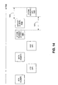
- FIG. 14 illustrates various mechanisms for client-initiated TXOPs for embodiments of the STT system 200, and in particular, mechanisms that focus on issues of NAV reset and backoff resumption involving CF-end frames or frames acting in particular circumstances with similar functionality to CF-end frames.
- the description that follows is based in part on the previous discussion corresponding to FIG. 7 for the case where STA1 is a client and STA2 is an AP.
- the client may transmit a short frame (EIFS set frame) 1404 with a defined frame check sequence (FCS) field 110 ( FIG.
- EIFS set frame short frame
- FCS defined frame check sequence
- the AP 202 delays (e.g., by SIFS + EIFS set frame + EIFS - DIFS - CF-end frame, represented by duration interval 1401) the sending of the CF-end frame 1406 so that the transmission of frame 1406 finishes exactly (or substantially so) when the EIFS-DIFS finishes (the EIFS-DIFS represented by the duration interval denoted by 1403), so that either client (e.g., 204, 206) starts DIFS (or more general, AIFS) at the same time.
- the DIFS refers to a first fixed part of the DCF backoff (DIFS)
- the AIFS refers to the EDCA backoff (AIFS).
- EIFS set frame 1404 causes AIFS to start for clients 204, 206 that cannot receive the CF-end 1406 from the AP 202.
- the CF-end frame 1406 from the AP 102 is transmitted during this time, such that all nodes start DIFS (or AIFS) at the same time.
- the EIFS set frame 1404 can be a zero length frame (e.g., a preamble without a MAC payload).
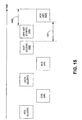
- FIG. 15 is a block diagram that illustrates the principles of the mechanism shown in FIG. 14 , without the use of CF-end frames.
- the CF-end frame 1402 of FIG. 14 is replaced with an EOT frame 1502
- the CF-end frame 1406 of FIG. 14 is replaced with an ACK frame 1504.
- the mechanism illustrated in FIG. 15 can be used to resume the backoff for all nodes within the range of either the client 204 or the AP 202 or both in the network at the same time (e.g., without part of the nodes having to wait for an EIFS to finish).
- the EOT frame 1502 is sent to the AP 202, followed after an SIFS interval by the EIFS set frame 1404.
- the AP 202 responds to the EOT frame 1502 (and ignores the EIFS set frame 1404) with the ACK frame 1504.
- the ACK frame 1504 ends at the same time as the interval 1403 after the end of the EIFS set frame 1404. Note that in some embodiments, both the AP and the client can start an EIFS set frame at the same, or substantially same, time.
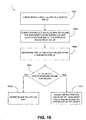
- one method embodiment of the STT system 200 encompassing these mechanisms, the method referred to as 200e and shown in FIG. 16 , comprises the client 204 sending a final data frame of a TXOP to the AP 202 (1602), the final frame having the form of a CF-end frame specific to a given AP or an EOT frame, sending an EIFS set frame, receiving by the AP 202 the CF-end frame after a defined interval (the defined interval being a SIFS, a PIFS, or duration 1401 described in association with FIG.
- a defined interval being a SIFS, a PIFS, or duration 1401 described in association with FIG.
- the CF-end frame acts to clear the NAV (1612), as described above.
- each device participating in the methodology illustrated in FIG. 16 performs portions of the described method 200e that can be described similarly to the manner such perspective-based methods have been described previously in FIGS. 10-12 , and thus omitted here for brevity.
- a symmetric transmit opportunity (TXOP) truncation method comprising:
- receiving the frame comprises receiving a CF-end frame.
- receiving the frame comprises receiving a CF-end frame having an address of the second station.
- receiving the frame comprises receiving at a client station or an access point.
- sending the second frame comprises sending a CF-end response frame to the first station, the second station, or a third station.
- sending the second frame comprises including an address of the first station, an address of the second station, or an address of a third station.
- sending the second frame comprises sending to a client station or an access point.
- J The method of I, further comprising, responsive to receiving the second frame at the third station, sending a third frame that truncates the TXOP around the third station.
- sending the third frame comprises sending the third frame with an address of the third station.
- sending comprises sending after a short interframe space (SIFS) interval or a PCF interframe space (PIFS) interval.
- SIFS short interframe space
- PIFS PCF interframe space
- receiving comprises receiving with a NAV duration value comprising a time after the second frame is expected to be sent.
- receiving comprises receiving the frame with a physical layer convergence protocol duration substantially equal to a duration of the frame plus a SIFS interval plus an expected duration of the second frame.
- a symmetric transmit opportunity (TXOP) truncation method comprising receiving a frame from an access point (AP) that includes an indicator of an end of a TXOP; responsive to receiving the indicator, sending a first frame that truncates the TXOP around a first station; receiving the first frame at the AP; and responsive to receiving the first frame at the AP, sending a second frame that truncates the TXOP around the AP.
- TXOP transmit opportunity
- receiving the frame comprises receiving a data frame.
- sending the first frame and sending the second frame comprises sending the first frame and the second frame with an address of the AP.
- a symmetric transmit opportunity (TXOP) truncation method comprising:
- V The method of T, wherein sending the first frame and sending the second frame comprise sending an end of transmission (EOT) frame and an acknowledgement frame, respectively.
- EOT end of transmission
- a symmetric transmit opportunity (TXOP) truncation system comprising: a processor configured with logic to receive a frame that truncates a TXOP around a first station and, responsive to receiving the frame, the processor further configured with the logic to send a second frame that truncates the TXOP around a second station.
- TXOP transmit opportunity
- AA The system of Z, wherein the frame comprises a CF-end frame.
- AC The system of Z, wherein the logic resides in a client station or an access point.
- AD The system of Z, wherein the processor is further configured with the logic to send a CF-end response frame to the first station, a second station, or a third station.
- AE The system of Z, wherein the second frame comprises an address of the first station, an address of the second station, or an address of a third station.
- AF The system of Z, wherein the processor is further configured with the logic to send to a client station or an access point.
- the system of Z further comprising a third station, the third station comprising a second memory with second logic and a second processor configured with the second logic to receive the second frame.
- AI The system of AH, wherein the third frame comprises an address of the third station.
- AK The system of Z, wherein the logic is embodied in a computer, consumer electronic device, set-top box, television set, video storage system, telecommunication device, or personal digital assistant (PDA).
- PDA personal digital assistant
- a symmetric transmit opportunity (TXOP) truncation system comprising means for receiving a frame that truncates a TXOP around a first station; and responsive to receiving the frame, means for sending a second frame that truncates the TXOP around a second station.
- TXOP transmit opportunity
- a symmetric transmit opportunity (TXOP) truncation system comprising:
- a first station comprising first logic to receive a frame from an access point (AP) that includes an indicator of an end of a TXOP and, responsive to receiving the indicator, send a first frame that truncates the TXOP at the first station; and the AP comprising second logic to receive the first frame, and responsive to receiving the first frame, send a second frame that truncates the TXOP at the AP.
- AP access point
- AN The system of AM, wherein the frame comprises a data frame.
- AO AO.
- ACK acknowledgement
- the system of AP wherein the address of the AP comprises an address in the BSSID field of the first or second frame.
- AR The system of AM, wherein the first logic and the second logic are each embodied in a wired device or a wireless device.
- AS The system of AM, wherein the first logic and the second logic are each embodied in a computer, consumer electronic device, set-top box, television set, video storage system, telecommunication device, or personal digital assistant (PDA).
- PDA personal digital assistant
- a symmetric transmit opportunity (TXOP) truncation system comprising:
- AP access point
- a symmetric transmit opportunity (TXOP) truncation system comprising:
- first station comprising first logic to send a first frame and an extended interframe space (EIFS) set frame after the first frame; and a second station configured with second logic to send a second frame having a completed transmission corresponding to time based on an interval of EIFS less DIFS, the interval commencing from an end of the short frame.
- EIFS extended interframe space
- AV The system of AU, wherein the first frame and the second frame each comprise a CF-end frame.
- AW The system of AU, wherein the first frame and the second frame comprise an end of transmission (EOT) frame and an acknowledgement frame, respectively.
- EOT end of transmission
- AX The system of AU, wherein sending of the second frame is independent of the presence of the EIFS set frame.
- AY The system of AU, wherein the first logic and the second logic are each embodied in a wired device or a wireless device.
- AZ The system of AU, wherein the first logic and the second logic are each embodied in a computer, consumer electronic device, set-top box, television set, video storage system, telecommunication device, or personal digital assistant (PDA).
- PDA personal digital assistant
- a symmetric transmit opportunity (TXOP) truncation system comprising:
- a symmetric transmit opportunity (TXOP) truncation method comprising:
Landscapes
- Engineering & Computer Science (AREA)
- Computer Networks & Wireless Communication (AREA)
- Signal Processing (AREA)
- Mobile Radio Communication Systems (AREA)
- Telephonic Communication Services (AREA)
- Compression Or Coding Systems Of Tv Signals (AREA)
Description
- The present disclosure is generally related to communication systems and methods and, more particularly, is related to collision avoidance systems and methods in wireless networks.
- Communication networks come in a variety of forms. Notable networks include wireline and wireless. Wireline networks include local area networks (LANs), DSL networks, and cable networks, among others. Wireless networks include cellular telephone networks, classic land mobile radio networks and satellite transmission networks, among others. These wireless networks are typically characterized as wide area networks. More recently, wireless local area networks and wireless home networks have been proposed, and standards, such as Bluetooth and IEEE 802.11, have been introduced to govern the development of wireless equipment for such localized networks.
- A wireless local area network (LAN) typically uses infrared (IR) or radio frequency (RF) communication channels to communicate between portable or mobile computer terminals and access points (APs) or base stations. These APs are, in turn, connected by a wired or wireless communications channel to a network infrastructure which connects groups of access points together to form the LAN, including, optionally, one or more host computer systems.
- Wireless protocols such as Bluetooth and IEEE 802.11 support the logical interconnections of such portable roaming terminals having a variety of types of communication capabilities to host computers. The logical interconnections are based upon an infrastructure in which at least some of the terminals are capable of communicating with at least two of the APs when located within a predetermined range, each terminal being normally associated, and in communication, with a single one of the access points. Based on the overall spatial layout, response time, and loading requirements of the network, different networking schemes and communication protocols have been designed so as to most efficiently regulate the communications.
- IEEE Standard 802.11 ("802.11") is set out in "Wireless LAN Medium Access Control (MAC) and Physical Layer (PHY) Specifications" and is available from the IEEE Standards Department, Piscataway, N.J. The IEEE 802.11 standard permits either IR or RF communications at 1 Mbps, 2 Mbps and higher data rates, a medium access technique similar to carrier sense multiple access/collision avoidance (CSMA/CA), a power-save mode for battery-operated mobile stations, seamless roaming in a full cellular network, high throughput operation, diverse antenna systems designed to eliminate "dead spots," and an easy interface to existing network infrastructures. The IEEE Standard 802.11b extension supports data rates up to 11 Mbps.
- The current 802.11 standard describes several methods to set a virtual carrier sense, referred to as a network allocation vector or NAV, most notably by request to send/clear to send (RTS/CTS) mechanisms. The sending of an RTS frame (herein, RTS frame also referred to as, simply, RTS) sets a NAV locally around the sender of the RTS, and the sending of a CTS frame (herein, CTS frame is also referred to as CTS) does the same locally around the sender of the CTS (e.g., the receiver of the RTS).
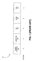
- One problem that exists in current implementations under 802.11 involves what is referred to as a hidden node problem. For instance, in an infrastructure mode of a wireless LAN system, a first device may communicate frames to the AP and vice versa. Similarly, a second device may communicate frames to the AP, and vice versa. However, the second device may not detect transmissions from the first device (hence the phrase hidden node), for instance if the distance between the first and second device is too great. Because of the hidden node problem, various complications may arise in terms of collision avoidance and symmetry of response among devices, causing inequity in terms of opportunities for access to a shared medium of the communication system. For instance, in 802.11 compliant systems, the NAV can be reset by an access point (AP) through the transmission of what is commonly referred to as a CF-end frame. One exemplary frame format for a CF-
end frame 10 is shown inFIG. 1 , and comprises two octets (exemplary quantity of octets shown beneath the frame 10) corresponding to aframe control field 102, two octets corresponding toduration field 104, six octets corresponding to a receiver address (RA)field 106, which usually contains the Broadcast Address (BC), six octets corresponding to a basic service set identifier (BSSID)field 108, and four octets corresponding to a frame check sequence (FCS)field 110. When the distance between a client station and an AP is large, one possible effect is that the area where the CF-end frame 10 is not received will not reset the NAV, resulting in inequitable access as described above. -
WO 2005/039105 discloses high speed media access control and direct link protocol. - Aspects of the invention are recited in the independent claims and preferred features are set out in the dependent claims.>
- Embodiments of the present disclosure provide symmetric transmit opportunity (TXOP) truncation systems and methods in a wireless network. Briefly described, one embodiment of a method, among others, comprises receiving a frame that truncates a TXOP around a first station, and responsive to receiving the frame, sending a second frame that truncates the TXOP around a second station.
- Another method embodiment, among others, comprises receiving a frame from an access point (AP) that includes an indicator of an end of a TXOP, responsive to receiving the indicator, sending a first frame that truncates the TXOP around a first station, receiving the first frame at the AP, and responsive to receiving the first frame at the AP, sending a second frame that truncates the TXOP around the AP.
- Another method embodiment, among others, comprises sending at a first station a first frame, sending at the first station an extended interframe space (EIFS) set frame after the first frame, and sending at a second station a second frame having a completed transmission corresponding to time based on an interval of EIFS less DIFS, the interval commencing from an end of the short frame.
- One system embodiment, among others, comprises a processor configured with logic to receive a frame that truncates a TXOP around a first station and, responsive to receiving the frame, the processor further configured with the logic to send a second frame that truncates the TXOP around a second station.
- Another system embodiment, among others, comprises means for receiving a frame that truncates a TXOP around a first station, and responsive to receiving the frame, means for sending a second frame that truncates the TXOP around a second station.
- Other systems, methods, features, and advantages of the present disclosure will be or become apparent to one with skill in the art upon examination of the following drawings and detailed description. It is intended that all such additional systems, methods, features, and advantages be included within this description, be within the scope of the present disclosure, and be protected by the accompanying claims.
- Many aspects of the disclosure can be better understood with reference to the following drawings. The components in the drawings are not necessarily to scale, emphasis instead being placed upon clearly illustrating the principles of the present disclosure. Moreover, in the drawings, like reference numerals designate corresponding parts throughout the several views.
-
FIG. 1 is a block diagram that illustrates one exemplary frame format for a CF-end frame. -
FIG. 2 is a block diagram of an exemplary environment in which various embodiments of a symmetric transmit opportunity (TXOP) truncation (STT) system may be implemented. -
FIGS. 3A-3B are block diagrams of that illustrate extended interframe space (EIFS) avoidance aspects to embodiments of the STT system as shown inFIG. 2 . -
FIG. 4 is a block diagram that illustrates a mechanism employed by one embodiment of the STT system shown inFIG. 2 for an access point (AP) initiated TXOP where the AP signals the end of TXOP by setting an end of TXOP (EOT) indication on the final transmission to a client. -
FIG. 5 is a block diagram that illustrates an alternative to the mechanism shown inFIG. 4 where the AP sends a CF-end with a client address, which is followed by a CF-end from the client with the same address of the client. -
FIG. 6 is a block diagram that illustrates an alternative to the mechanism shown inFIG. 4 where the AP sends a CF-end with the client address in the location of a basic service set identifier (BSSID) field and the client responds with a CF-end with the BSSID and the AP responds with a final CF-end. -
FIG. 7 is a block diagram that illustrates a mechanism employed by one embodiment of the STT system shown inFIG. 2 for a station-initiated TXOP that is terminated by a first station sending a CF-end with the address of the second station in the location of the BSSID field and the second station responding with a CF-end with the second station address in the BSSID field. -
FIG. 8 is a block diagram that illustrates a mechanism employed by one embodiment of the STT system shown inFIG. 2 with a BSSID of a station which either transmitted the latest beacon in an independent basic service set (IBSS) or an AP in a Direct Link communication. -
FIG. 9 is a block diagram that illustrates a mechanism employed by one embodiment of the STT system shown inFIG. 2 for a station-initiated TXOP that is terminated by a first station sending a CF-end to a second station, which responds with a CF-end to the third station, the latter which responds with a final CF-end. -
FIG. 10 is a flow diagram that illustrates a method embodiment corresponding to the mechanism shown inFIG. 4 . -
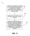
FIG. 11 is a flow diagram that illustrates a method embodiment corresponding to the mechanisms shown inFIGS. 5 and7 . -
FIG. 12 is a flow diagram that illustrates a method embodiment corresponding to the mechanisms shown inFIG. 6 . -
FIG. 13 is a flow diagram that illustrates a method embodiment corresponding to the mechanisms shown inFIGS. 8-9 . -
FIG. 14 is a block diagram that illustrates a NAV reset mechanism employed by an embodiment of the STT system shown inFIG. 2 . -
FIG. 15 is a block diagram that illustrates an alternative to the NAV reset mechanism shown inFIG. 14 without using CF-end frames. -
FIG. 16 provides a flow diagram that illustrates a method embodiment corresponding to the NAV reset mechanisms shown inFIGS. 14-15 . - Disclosed herein are various embodiments of symmetric transmit opportunity (TXOP) truncation (STT) systems and corresponding mechanisms or methods in a wireless network (herein, individually or collectively referred to also as an STT system or STT systems). The STT systems described herein comprise functionality to truncate a TXOP in a symmetric manner in a plurality of devices. That is, in various STT systems and methods described herein, both access points (APs) and client stations (herein, clients) are also allowed to truncate their TXOPs by transmitting a CF-end frame. This truncation is referred to as a TXOP truncation, where a NAV is first set for some maximum duration of time (e.g., the TXOP limit) and then reset when no more traffic (e.g., of frames) is left and there is some NAV time that still remains. In general, a TXOP comprises a signal exchange which may begin with the transmission of a short frame such as an RTS or CTS and ends with the last frame sent or received by the sender of the short frame (e.g., sender of the RTS or CTS). The truncation at both clients and APs resolve the various problems resulting from a reset that is not symmetrical, such as in conventional systems where the reset comes from a single device (though set by both devices through the RTS/CTS mechanisms). Various embodiments of the STT systems provide one or more mechanisms for the symmetrical truncation of TXOPs.
- Thus, although described mostly in the context of a wireless local area network (WLAN) environment having a basic service set (BSS) configured in an infrastructure mode, the various embodiments of the STT systems described herein may similarly be applied to other systems and environments, such as ad hoc systems (e.g., independent BSS (IBSS) systems) or DLC systems, as well as other communication system environments. Additionally, although IEEE 802.11 is prominently used herein as an example of a standard used in the disclosed exemplary wireless networks, the various systems and methods described herein may apply to virtually any wireless network. Further, some embodiments of the STT systems may include some or all of the functionality of collision avoidance systems (CA systems) described in the co-pending application having serial number 11/557,516 and incorporated herein by reference in its entirety.
-
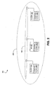
FIG. 2 shows an exemplary wireless LAN (WLAN)environment 100 in which various embodiments of a symmetric transmit opportunity (TXOP) truncation (STT)system 200 may be implemented. In general, theSTT system 200 is configured as a basic service set (BSS), which comprises a plurality of stations or nodes, such asstations stations - The
STT system 200 shown inFIG. 2 comprises, in one embodiment, an access point (AP) station 202 (herein, also referred to, simply, as an AP) and one ormore client stations 204, 206 (herein, also referred to individually or collectively as client(s)). TheSTT system 200 is configured in what may be referred to as an infrastructure mode, wherebyclients AP 202 and not with each other. However, the various embodiments ofSTT systems 200 are not limited to such arrangements, and in some embodiments, may be arranged in ad hoc or direct link communication configurations. Included within each of theAP 202 andclients control logic 300. Thecontrol logic 300 implements MAC layer and PHY layer services. The MAC layer services provide the capability for a given station to exchange MAC frames. The MAC layer services provide management, control, or data frames for transmission betweenstations control logic 300 can be configured using a plurality of modules (e.g., hardware and/or software), each with distinct functionality, or as a single module comprising a plurality of functionality. - The
control logic 300 can be implemented in hardware, software, or a combination thereof. When implemented in whole or in part by software,control logic 300 is implemented in software stored in a memory that is executed by a suitable instruction execution system. When implemented in whole or in part by hardware, thecontrol logic 300 can be implemented with any or a combination of the following technologies, which are all well known in the art: a discrete logic circuit(s) having logic gates for implementing logic functions upon data signals, an application specific integrated circuit (ASIC) having appropriate combinational logic gates, a programmable gate array(s) (PGA), a field programmable gate array (FPGA), etc. In one embodiment, thecontrol logic 300 may include a PHY layer processor, MAC layer processor, or a combination of both (in the same or separate units), including, but not limited to, a digital signal processor (DSP), a microprocessor unit (MCU), a general purpose processor, and an application specific integrated circuit (ASIC), among others. - The
AP 202 is typically connected to a wired network (e.g., Ethernet), not shown. In general, the clients, such asclient 204, connect to theAP 202 through a scanning process. The scanning process can either be performed passively by listening for a beacon transmitted by one ormore APs 202, or actively by sending out probes to one ormore APs 202 and choosing an AP that provides the best connection (e.g., in terms of signal strength and/or bit error ratio (BER)). After an AP is chosen, such asAP 202, an authentication process occurs between theclient 204 and theAP 202, and then association between theclient 204 and theAP 202 may begin. - Association involves the communication between the
clients AP 202 via a shared wireless medium 208. In one implementation, theclient 206 may represent a hidden node toclient 204, and vice versa. Various mechanisms or methods for signal exchanges are illustrated inFIGS. 3A-16 to highlight various features of embodiments of theSTT system 200. Although described below in the context of theAP 202 or client 204 (or similarly client 206) sending or receiving various transmissions, it can be understood in the context of this disclosure that the effectuating of the various functionality of theSTT system 200 is through thecontrol logic 300 of each station (node). Further, the various interframe spaces (e.g., extended interframe space (EIFS), short interframe space (SIFS), etc.) described in 802.11 and understood by those having ordinary skill in the art are omitted from the various figures (and corresponding description) except where helpful to the understanding of the various embodiments. - Before describing the various symmetrical TXOP truncation mechanisms of embodiments of the
STT system 200, an embodiment of anSTT system 200 that performs an AP-initiated TXOP is described in association withFIGS. 3A-3B . That is,FIGS. 3A-3B show one mechanism used by an embodiment of theSTT system 200 to set a NAV and/or avoid EIFS for an AP-initiated TXOP. Referring toFIG. 3A , theAP 202 sets a NAV prior to aTXOP 302 by starting theTXOP 302 with a short frame 304 (e.g., short to reduce the probability of error) at a low basic rate. Note that blocks 302 and 304 collectively comprise a TXOP. Theshort frame 304 contains a duration value (e.g., the NAV setting) equal to the expected length of theTXOP 302. Referring toFIG. 3B , theAP 202 avoids any EIFS at the end of theTXOP 302 by sending a short frame 306 (typically containing a duration value of zero) at a low basic rate as the final frame of theTXOP 302. Note that blocks 302 and 306 collectively comprise a TXOP. In each case, the rate is selected such that frames from theAP 202 reach all nodes in the network (e.g., BSS). - The description that follows and the associated figures (
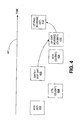
FIGS. 4-9 ) disclose various mechanisms employed (implemented) by certain embodiments of theSTT system 200 that provide for symmetrical TXOP truncation using CF-end frames (herein, each of these frames also simply referred to as CF-end). In particular, various mechanisms of communication between devices of one or more STT system embodiments are illustrated inFIGS. 4-9 and explained in the corresponding text. For instance, shown inFIG. 4 are blocks representing respective frames that are passed between theclient 204 and theAP 202 to provide for symmetrical TXOP truncation. As noted fromFIGS. 4-9 , the AP-sourced frames are represented with blocks in the top row (indicated in parenthesis, with "AP"), and the client-sourced frames are represented with blocks in the second row (as indicated in the parenthesis as "client"). The sequence of frame transmission advances in time from left to right, as represented by thearrow time line 401. For instance, for the exemplary communication shown inFIG. 4 , an RTS frame sent by theAP 202 begins the sequence, and a CF-end sent by theAP 202 ends the sequence. Note that the first address (e.g., BC) is the receiver address, which should be the broadcast address so that the CF-end is received by all stations. The second address (e.g., BSSID) is usually the transmitter address, but in one or more embodiments described herein, comprises the unicast destination address. - In particular, the AP 202 (not shown, but implied as denoted by the "AP" in parenthesis) sends an RTS frame (or RTS) 402, and the client 204 (not shown, but implied as denoted by the "client" in parenthesis) responds by sending a CTS frame (or CTS) 404. The sending of the RTS 402 and
CTS 404 results in the setting of a NAV around (e.g., close enough to decode frame transmissions all or at least most of the time) the respective devices. TheAP 202 sends one or more data frames 406, each of which are acknowledged by theclient 204 with an acknowledgement (ACK)frame 408. Thefinal data frame 406 from theAP 202 to theclient 204 is "tagged" with an end of TXOP (EOT) indication. This EOT indication comprises a signal or flag to theclient 204 to respond with a CF-end frame 410 after a SIFS interval. In some implementations, the CF-end frame 410 may be preceded by a mandatory response frame, such as the ACK frame 408 (or a block acknowledgement (BA) frame, the latter not shown). A basic service set identifier (BSSID) field of the CF-end frame 410 carries a BSSID (e.g., MAC address) of theAP 202. TheAP 202 recognizes its BSSID in the received CF-end frame 410 and responds to this CF-end frame 410 with a CF-end frame 412. By theAP 202 sending the CF-end frame 412, the TXOP is actively truncated by bothdevices -
FIG. 5 illustrates an alternative to the mechanism shown inFIG. 4 . That is, the final frame in the TXOP sent by theAP 202 is a CF-end frame 502 comprising the address (e.g., MAC address) of theclient 204 inside the BSSID field. Theclient 204 recognizes its address in the CF-end frame 502 and responds after a SIFS interval with a CF-end frame 504. The CF-end frame 504 also comprises the client address inside the location of the BSSID field. This mechanism illustrated inFIG. 5 is referred to as a "CF-end to self." -
FIG. 6 illustrates an alternative to the mechanism shown inFIG. 4 . TheAP 202 sends a CF-end frame 602 with the client MAC address inside the BSSID field. The client responds with a CF-end frame 604 having the BSSID of theAP 202, to which theAP 202 responds with a CF-end frame 606 with the BSSID of theAP 202. Hence, theAP 202 acts as the final transmitter of the final CF-end frame, which may be desirable in relation to the EIFS inside a BSS since all associated clients receive the final CF-end frame (e.g., CF-end frame 606) from theAP 202. The first CF-end frame 602 uses a non-basic rate, and thereby functions similarly to the EOT frame indication (of final frame 406) shown in and described in association withFIG. 4 . By using a non-basic rate for the first CF-end frame 602, NAV truncation functionality is absent. That is, a CF-end frame is effective for NAV truncation when sent at a basic rate that all clients inside a defined BSS can receive and decode - Having described various exemplary mechanisms used by the
STT system 200 for providing symmetrical truncation, the following description (and associated figures) generalizes some of the above-noted mechanisms for communications between stations (e.g., eitherAP 202 orclients 204, 206) and provides additional mechanisms. That is,FIGS. 7-9 provide a generalized illustration of the above-described mechanisms, in addition to describing additional mechanisms, by showing an exchange of frames between two stations, station 1 (STA1) (shown in a top row ofFIGS. 7-9 ) and station 2 (STA 2) (shown in a second row ofFIGS. 7-9 ). In some embodiments, there may be an exchange of frames with a third station such as an AP or other device (shown in a third row at the bottom ofFIGS. 8-9 ). The explanation of the various mechanisms shown inFIGS. 7-9 is directed to the exchange of frames that commence after the exchange of CTS/RTS frames and data and ACK frames, the latter of which have already been described above in association withFIGS. 4-6 . -
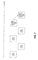
FIG. 7 illustrates a general principle of certain embodiments of theSTT system 200 that any station that receives a CF-end frame 702 with its corresponding MAC address inside the location of the BSSID field responds to the CF-end frame 702 with a CF-end frame 704. The address used inside the CF-end frame 702 depends on the specific implementation. In general, if a CF-end frame 704 is required (a determination to be made by a client or an AP), the address of the transmitter of the next CF-end frame 704 is included inside the location of the BSSID field of CF-end frame 702. If no CF-end frame 704 (also referred to herein as a CF-end response frame) is required and the CF-end frame 702 is the final frame of the sequence, the station's (e.g., STA2) own address is included in the BSSID field, or the broadcast address (BC), or any other address which is not immediately associated with another station address. Such a scheme is applicable in an IBSS or Direct Link environment as well. In general, a client in infrastructure mode would typically include the BSSID of the AP, so that the AP generates a CF-end response. Further, a client in IBSS mode may include the MAC address of the peer node to which it is communicating during the TXOP. An AP may or may not include an address other than a BSSID of the AP. - Consider the case where STA1 comprises a
client station 204, and STA2 comprises an AP station (or simply, AP) 202. The mechanism shown inFIG. 7 enables theAP 202 to respond to a CF-end 702, which contains a matching BSSID (e.g., MAC address) with another CF-end 704 after SIFS (which in some implementations, may be a PIFS interval). The CF-end 702 transmitted by theclient station 204 comprises the final frame in the TXOP ofclient station 204, and in one embodiment, is an unacknowledged frame (hence, it is safe to transmit a CF-end 704 after SIFS). The BSSID makes the CF-end 702 specific to one AP, avoiding collisions between multiple APs transmitting a CF-end 704. The CF-end 704 clears the NAV around theAP 202, which covers the entire BSS. Note that some implementations may not require the CF-end 704. For instance, when the distance between theAP 202 and theclient station 204 is small, a single CF-end from either theAP 202 or theclient station 204 roughly resets the EIFS in the same coverage area, because the coverage areas for both devices largely overlap. The determination by theAP 202 to send a CF-end response (CF-end 704) can be based on the estimated distance of associatedclient stations client stations - Continuing the case where STA1 is a
client 204 and STA2 is anAP 202, theclient 204 may send a CF-end 702 with a duration value (which sets a NAV) corresponding to a defined time after the expected CF-end 704 to be sent by theAP 202. TheAP 202 sends a CF-end 704 (CF-end response) with a duration of zero, which causes receivers of each CF-end to resume backoff at exactly, or substantially exactly, the same time (and hence, in one embodiment, superceding existing rules that allow an EIFS to follow a CF-end). Theclient 204 may also send a CF-end 702 with a physical layer convergence protocol (PLCP) duration (which is signaled inside a SIG field or L-SIG field of the frame) equal to the CF-end itself plus SIFS plus the expected CF-end response duration from theAP 202. TheAP 202, in one embodiment, is allowed to ignore this physical duration and respond with a CF-end 704 a SIFS interval after the end of the actual transmission of the CF-end 702, as can be determined from the indicated rate and size of the CF-end 702 (e.g., 20 octets without an HT control field, 24 octets with an HT control field). The CF-end 704, in one embodiment, comprises a regular PLCP duration. The mechanisms described below in association withFIGS. 14 and15 address situations where there is a difference in when the NAV gets reset and backoff resumes. - In some embodiments, a third CF-end frame may be added to the frame sequence illustrated in
FIG. 7 when the second station includes the BSSID. Such a situation is illustrated inFIG. 8 , which includes the addition of an AP (implicitly represented by the bottom or third row frame 802). The TXOP is initiated by STA1 sending a CF-end frame 802 to STA2, which responds with a CF-end frame 804 to the AP. As shown, the AP responds with a final CF-end frame 806 with the BSSID inside the BSSID field of CF-end frame 806. - In an IBSS implementation, the BSSID may be recognized by the station that transmitted the final IBSS beacon, as illustrated in
FIG. 9 . As shown, STA1 sends a CF-end frame 902 addressed at STA2. STA2 responds with a CF-end frame 904 addressed at the BSSID of STA2. STA3 responds with a CF-end frame 906. The BSSID can be the address of the station (e.g., STA3) that transmitted the latest beacon in an IBSS, or it can be the address of the AP in case the communication between STA1 and STA2 comprises a Direct Link communication. - In some embodiments, the receiver address (RA) of a CF-end frame is equal to the broadcast address, which ensures that all stations within range receive the CF-end frame and process the same. The location of the BSSID can be used to indicate the destination of the CF-end. Further, in some embodiments, the recognition of the CF-end type/subtype is enough for a receiver to truncate the NAV. In such implementations, the RA of the CF-end frame can be used to store the CF-end responder address, while the BSSID field can be used to store the BSSID.
- Having described various embodiments of the
STT system 200 above, it can be appreciated in the context of this disclosure that one method embodiment, referred to asSTT method 200a corresponding to the mechanism shown inFIG. 4 and shown in the flow diagram ofFIG. 10 , comprises sending by an AP a final data frame of a transmit opportunity (TXOP) with an end of transmit opportunity (EOT) indicator included therein (1002), receiving by a client the final data frame (1004), the client responding by sending a CF-end frame, with an identifier (e.g., MAC address, etc.) of the AP included therein, to the AP to truncate the TXOP around the client (1006), the AP receiving the CF-end frame with the identifier (1008), and the AP sending a CF-end frame with the same identifier to the client to truncate the TXOP around the AP (1010). - It can be appreciated that portions of the
method embodiment 200a are implemented at each device, and hence such portions can be described from the perspective of the individual devices of thesystem 200. For instance, one method embodiment corresponding tomethod 200a, viewed from the perspective of an AP, comprises sending (by an AP) a final data frame of a transmit opportunity (TXOP) with an end of transmit opportunity (EOT) indicator included therein, and responsive to receiving a CF-end frame with an identifier of the AP included therein to truncate the TXOP around the client, sending a CF-end frame with the same identifier to the client to truncate the TXOP around the AP. - Another method embodiment corresponding to
method 200a, from the perspective of a client, comprises receiving (by a client) a final frame of a transmit opportunity (TXOP) from an AP, the final data frame having an end of transmit opportunity (EOT) indicator included therein, responding to the final frame by sending a CF-end frame, with an identifier of the AP included therein, to the AP to truncate the TXOP around the client and to prompt the AP to send a CF-end frame to truncate the TXOP around the AP. - Another embodiment, referred to as STT method 200b corresponding to the mechanisms illustrated in
FIGS. 5 and7 and shown in the flow diagram ofFIG. 11 , comprises sending, by a first station (e.g., an AP), at the end of a TXOP a CF-end frame with an address of a second station (e.g., a client) included therein to truncate a TXOP around the first station (1102), receiving by the second station the CF-end frame from the first station (1104), the second station responding to the first station by sending a CF-end frame with the address of the second station included therein to truncate the TXOP around the second station (1106). - It can be appreciated that portions of the method embodiment 200b are implemented at each device (e.g., stations, whether configured as an AP or client), and hence such portions can be described from the perspective of the individual devices of the
system 200. For instance, one method embodiment corresponding to method 200b implemented at a first station (e.g., AP) comprises receiving a final frame of a TXOP from a second station (e.g., client) at the first station, and responsive to receiving the final frame of the TXOP, sending, at the end of the TXOP, a CF-end frame with an address of the second station included therein to truncate a TXOP around the first station and to prompt the second station to send a CF-end frame to truncate the TXOP around the second station. - Additionally, one method embodiment corresponding to method 200b implemented at a second station (e.g., client) comprises receiving (at the second station) a CF-end frame with an address of the second station included therein, the CF-end used to truncate a TXOP around a first station (e.g., AP), and responding to the first station by sending a CF-end frame with the address of the second station included therein to truncate the TXOP around the second station.
- Another method embodiment, referred to as
STT method 200c corresponding to the mechanism illustrated inFIG. 6 and shown in the flow diagram ofFIG. 12 , comprises an AP sending a CF-end frame at a non-basic rate (and hence acting as an EOT indicator) with the address of the client included therein (1202), the client receiving the CF-end frame (1204), the client responding by sending a CF-end frame having the address of the AP included therein, which truncates the TXOP around the client (1206), the AP receiving the CF-end frame sent by the client (1208), and the AP responding by sending a CF-end frame with the address of the AP included therein, resulting in the AP acting as the final transmitter of the final CF-end frame that truncates the TXOP around the AP (1210). - It can be appreciated that portions of the
method embodiment 200c are implemented at each device, and hence method embodiments can be described from the perspective of the AP and client. One method embodiment corresponding tomethod 200c implemented at an AP comprises an AP sending a CF-end frame at a non-basic rate (and hence acting as an EOT indicator) with the address of the client included therein, and responsive to receiving a client-TXOP truncating CF-end frame having the address of the AP included therein, responding by sending a CF-end frame with the address of the AP included therein, which truncates the TXOP around the AP. - Additionally, one method embodiment corresponding to
method 200c implemented at a client comprises receiving by a client a CF-end frame possibly at a non-basic rate (and hence acting as an EOT indicator) with the address of the client included therein, and responding by sending a CF-end frame having the address of the sending AP included therein, which truncates the TXOP around the client and prompts the AP to send a final CF-end frame that truncates the TXOP around the AP. - Another method embodiment, referred to as STT method 200d corresponding to the mechanisms illustrated in
FIGS. 8-9 and shown in the flow diagram ofFIG. 13 , comprises sending, by a first station, at the end of a TXOP a CF-end frame with an address of a second station included therein to truncate a TXOP around the first station (1302), receiving by the second station the CF-end frame from the first station (1304), the second station responding to the first station by sending a CF-end frame with an identifier included therein to a third station to truncate the TXOP around the second station (1306), the third station receiving the CF-end response frame (1308), the third station responding by sending a CF-end response frame with the identifier therein to the second station to truncate the TXOP around the third station (1310). - It can be appreciated by one having ordinary skill in the art, in the context of this disclosure, that each device participating in the methodology illustrated in
FIG. 13 performs portions of the described method 200d that can be described similarly to the manner such perspective-based methods have been described previously inFIGS. 10-12 , and thus omitted here for brevity. -
FIG. 14 illustrates various mechanisms for client-initiated TXOPs for embodiments of theSTT system 200, and in particular, mechanisms that focus on issues of NAV reset and backoff resumption involving CF-end frames or frames acting in particular circumstances with similar functionality to CF-end frames. The description that follows is based in part on the previous discussion corresponding toFIG. 7 for the case where STA1 is a client and STA2 is an AP. To solve the difference in when a NAV gets reset and the backoff resumes, the client may transmit a short frame (EIFS set frame) 1404 with a defined frame check sequence (FCS) field 110 (FIG. 1 ), which is not the correct FCS (e.g., if the FCS is correct, then stations start an EIFS rather than a DCF Interframe Space/Arbitration Interframe Space or DIFS/AIFS), at a SIFS time after the CF-end frame 1402. The transmission of thisshort frame 1404 in the manner as described above causes receivers (e.g.,clients 204, 206) to start an EIFS. TheAP 202 delays (e.g., by SIFS + EIFS set frame + EIFS - DIFS - CF-end frame, represented by duration interval 1401) the sending of the CF-end frame 1406 so that the transmission offrame 1406 finishes exactly (or substantially so) when the EIFS-DIFS finishes (the EIFS-DIFS represented by the duration interval denoted by 1403), so that either client (e.g., 204, 206) starts DIFS (or more general, AIFS) at the same time. The DIFS refers to a first fixed part of the DCF backoff (DIFS), and the AIFS refers to the EDCA backoff (AIFS). As is known, EDCA is similar to DCF but with QoS differentiation (802.11e). TheAP 202 does not start an EIFS and ignores the intermediate EIFS setframe 1404. Thus, theEIFS set frame 1404 causes AIFS to start forclients end 1406 from theAP 202. The CF-end frame 1406 from theAP 102 is transmitted during this time, such that all nodes start DIFS (or AIFS) at the same time. Note that in some embodiments, theEIFS set frame 1404 can be a zero length frame (e.g., a preamble without a MAC payload). -
FIG. 15 is a block diagram that illustrates the principles of the mechanism shown inFIG. 14 , without the use of CF-end frames. In other words, the CF-end frame 1402 ofFIG. 14 is replaced with anEOT frame 1502, and the CF-end frame 1406 ofFIG. 14 is replaced with anACK frame 1504. The mechanism illustrated inFIG. 15 can be used to resume the backoff for all nodes within the range of either theclient 204 or theAP 202 or both in the network at the same time (e.g., without part of the nodes having to wait for an EIFS to finish). TheEOT frame 1502 is sent to theAP 202, followed after an SIFS interval by theEIFS set frame 1404. TheAP 202, through asimilar delay 1401 and similar manner to the mechanism described in association withFIG. 14 , responds to the EOT frame 1502 (and ignores the EIFS set frame 1404) with theACK frame 1504. TheACK frame 1504 ends at the same time as theinterval 1403 after the end of theEIFS set frame 1404. Note that in some embodiments, both the AP and the client can start an EIFS set frame at the same, or substantially same, time. - Having described the various mechanisms shown in
FIGS. 14-15 , one method embodiment of theSTT system 200 encompassing these mechanisms, the method referred to as 200e and shown inFIG. 16 , comprises theclient 204 sending a final data frame of a TXOP to the AP 202 (1602), the final frame having the form of a CF-end frame specific to a given AP or an EOT frame, sending an EIFS set frame, receiving by theAP 202 the CF-end frame after a defined interval (the defined interval being a SIFS, a PIFS, orduration 1401 described in association withFIG. 14 ) (1606), and responsive to deciding to send the CF-end response frame or ACK frame, clearing the NAV for the network (e.g., BSS) by sending the CF-end response frame or ACK frame to the client 204 (1610). Responsive to deciding not to send the CF-end response frame, the CF-end frame acts to clear the NAV (1612), as described above. - It can be appreciated by one having ordinary skill in the art, in the context of this disclosure, that each device participating in the methodology illustrated in
FIG. 16 performs portions of the described method 200e that can be described similarly to the manner such perspective-based methods have been described previously inFIGS. 10-12 , and thus omitted here for brevity. - In view of the above description, it can be appreciated that various embodiments can be described in the following manner and are considered within the scope of the disclosure.
- A: A symmetric transmit opportunity (TXOP) truncation method, comprising:
- receiving a frame that truncates a TXOP around a first station; and responsive to receiving the frame, sending a second frame that truncates the TXOP around a second station.
- B. The method of A, wherein receiving the frame comprises receiving a CF-end frame.
- C. The method of A, wherein receiving the frame comprises receiving a CF-end frame having an address of the second station.
- D. The method of C, wherein a destination for the CF-end resides in a basic service set identification (BSSID) field.
- E. The method of A, wherein receiving the frame comprises receiving at a client station or an access point.
- F. The method of A, wherein sending the second frame comprises sending a CF-end response frame to the first station, the second station, or a third station.
- G. The method of A, wherein sending the second frame comprises including an address of the first station, an address of the second station, or an address of a third station.
- H. The method of A, wherein sending the second frame comprises sending to a client station or an access point.
- I. The method of A, further comprising receiving the second frame at a third station.
- J. The method of I, further comprising, responsive to receiving the second frame at the third station, sending a third frame that truncates the TXOP around the third station.
- K. The method of J, wherein sending the third frame comprises sending the third frame with an address of the third station.
- L. The method of A, wherein sending comprises sending after a short interframe space (SIFS) interval or a PCF interframe space (PIFS) interval.
- M. The method of A, wherein receiving comprises receiving with a NAV duration value comprising a time after the second frame is expected to be sent.
- N. The method of A, wherein receiving comprises receiving the frame with a physical layer convergence protocol duration substantially equal to a duration of the frame plus a SIFS interval plus an expected duration of the second frame.
- O. A symmetric transmit opportunity (TXOP) truncation method, comprising receiving a frame from an access point (AP) that includes an indicator of an end of a TXOP; responsive to receiving the indicator, sending a first frame that truncates the TXOP around a first station; receiving the first frame at the AP; and responsive to receiving the first frame at the AP, sending a second frame that truncates the TXOP around the AP.
- P. The method of O, wherein receiving the frame comprises receiving a data frame.
- Q. The method of O, further comprising receiving an acknowledgement (ACK) frame before receiving the first frame at the first station.
- R. The method of O, wherein sending the first frame and sending the second frame comprises sending the first frame and the second frame with an address of the AP.
- S. The method of R., wherein the address of the AP comprises an address in the BSSID field of the first or second frame.
- T. A symmetric transmit opportunity (TXOP) truncation method, comprising:
- sending at a first station a first frame; sending at the first station an extended interframe space (EIFS) set frame after the first frame; and sending at a second station a second frame having a completed transmission corresponding to time based on an interval of EIFS less DIFS, the interval commencing from an end of the short frame.
- U. The method of T, wherein sending the first frame and sending the second frame each comprise sending a CF-end frame.
- V. The method of T, wherein sending the first frame and sending the second frame comprise sending an end of transmission (EOT) frame and an acknowledgement frame, respectively.
- W. The method of T, wherein sending of the second frame is independent of the presence of the EIFS set frame.
- X. The method of T, wherein the EIFS set frame comprises a faulty frame check sequence (FCS).
- Y. The method of T, wherein the EIFS set frame consists of a PHY header.
- Z. A symmetric transmit opportunity (TXOP) truncation system, comprising: a processor configured with logic to receive a frame that truncates a TXOP around a first station and, responsive to receiving the frame, the processor further configured with the logic to send a second frame that truncates the TXOP around a second station.
- AA. The system of Z, wherein the frame comprises a CF-end frame.
- AB. The system of Z, wherein the frame comprises a CF-end frame having an address of the second station.
- AC. The system of Z, wherein the logic resides in a client station or an access point.
- AD. The system of Z, wherein the processor is further configured with the logic to send a CF-end response frame to the first station, a second station, or a third station.
- AE. The system of Z, wherein the second frame comprises an address of the first station, an address of the second station, or an address of a third station.
- AF. The system of Z, wherein the processor is further configured with the logic to send to a client station or an access point.
- AG. The system of Z, further comprising a third station, the third station comprising a second memory with second logic and a second processor configured with the second logic to receive the second frame.
- AH. The system of AG, wherein the second processor is configured with the second logic to, responsive to receiving the second frame, send a third frame that truncates the TXOP at the third station.
- AI. The system of AH, wherein the third frame comprises an address of the third station.
- AJ. The system of Z, wherein the logic is embodied in a wired device or a wireless device.
- AK. The system of Z, wherein the logic is embodied in a computer, consumer electronic device, set-top box, television set, video storage system, telecommunication device, or personal digital assistant (PDA).
- AL. A symmetric transmit opportunity (TXOP) truncation system, comprising means for receiving a frame that truncates a TXOP around a first station; and responsive to receiving the frame, means for sending a second frame that truncates the TXOP around a second station.
- AM. A symmetric transmit opportunity (TXOP) truncation system, comprising:
- a first station comprising first logic to receive a frame from an access point (AP) that includes an indicator of an end of a TXOP and, responsive to receiving the indicator, send a first frame that truncates the TXOP at the first station; and the AP comprising second logic to receive the first frame, and responsive to receiving the first frame, send a second frame that truncates the TXOP at the AP.
- AN. The system of AM, wherein the frame comprises a data frame.
- AO. The system of AM, wherein the first logic is further configured to receive an acknowledgement (ACK) frame before receiving the first frame.
- AP. The system of AM, wherein the first frame and the second frame each comprise an address of the AP.
- AQ. The system of AP, wherein the address of the AP comprises an address in the BSSID field of the first or second frame.
- AR. The system of AM, wherein the first logic and the second logic are each embodied in a wired device or a wireless device.
- AS. The system of AM, wherein the first logic and the second logic are each embodied in a computer, consumer electronic device, set-top box, television set, video storage system, telecommunication device, or personal digital assistant (PDA).
- AT. A symmetric transmit opportunity (TXOP) truncation system, comprising:
- means for receiving a frame from an access point (AP) that includes an indicator of an end of a TXOP and, responsive to receiving the indicator, means for sending a first frame that truncates the TXOP at the first station; and means for receiving the first frame, and responsive to receiving the first frame, means for sending a second frame that truncates the TXOP at the AP.
- AU. A symmetric transmit opportunity (TXOP) truncation system, comprising:
- a first station comprising first logic to send a first frame and an extended interframe space (EIFS) set frame after the first frame; and a second station configured with second logic to send a second frame having a completed transmission corresponding to time based on an interval of EIFS less DIFS, the interval commencing from an end of the short frame.
- AV. The system of AU, wherein the first frame and the second frame each comprise a CF-end frame.
- AW. The system of AU, wherein the first frame and the second frame comprise an end of transmission (EOT) frame and an acknowledgement frame, respectively.
- AX. The system of AU, wherein sending of the second frame is independent of the presence of the EIFS set frame.
- AY. The system of AU, wherein the first logic and the second logic are each embodied in a wired device or a wireless device.
- AZ. The system of AU, wherein the first logic and the second logic are each embodied in a computer, consumer electronic device, set-top box, television set, video storage system, telecommunication device, or personal digital assistant (PDA).
- BA. A symmetric transmit opportunity (TXOP) truncation system, comprising:
- means for sending at a first station a first frame and an EIFS set frame after the first frame; and means for sending at a second station a second frame having a completed transmission corresponding to time based on an interval of EIFS less DIFS, the interval commencing from an end of the short frame.
- BB. A symmetric transmit opportunity (TXOP) truncation method, comprising:
- sending at a first station a first frame addressed at a second station; and sending at the first and the second station an extended interframe space (EIFS) set frame after the first frame.
- BC. The method of BB, wherein sending the first frame comprises sending a CF-end frame.
- Any process descriptions or blocks in flow charts should be understood as representing modules, segments, or portions of code which include one or more executable instructions for implementing specific logical functions or steps in the process, and alternate implementations are included within the scope of the appended claims in which functions may be executed out of order from that shown or discussed, including substantially concurrently or in reverse order, depending on the functionality involved, as should be understood by those reasonably skilled in the art of the present disclosure.
- It should be emphasized that the above-described embodiments of the present disclosure are merely possible examples of implementations, merely set forth for a clear understanding of the principles of the disclosure. Many variations and modifications may be made to the above-described embodiment(s) of the disclosure without departing substantially from the scope of the appended claims. All such modifications and variations are intended to be included herein within the scope and protected by the following claims.
Claims (15)
- A symmetric transmit opportunity, TXOP, truncation method, comprising:receiving a frame (702, 802, 902, 1402, 1502) that truncates a TXOP around a first station (202, 204, 206); andresponsive to receiving the frame, sending a second frame (704, 804, 904, 1406, 1504) that truncates the TXOP around a second station (202, 204, 206).
- The method of claim 1, wherein receiving the frame (702, 802, 902, 1402) comprises receiving a CF-end frame.
- The method of claim 1, wherein receiving the frame (702, 802, 902, 1402) comprises receiving a CF-end frame having an address of the second station.
- The method of claim 3, wherein a destination for the CF-end resides in a basic service set identification, BSSID, field (108).
- The method of claim 1, wherein receiving the frame (702, 802, 902, 1402, 1502) comprises receiving at a client station or an access point, and/or wherein sending the second frame (704, 804, 904, 1406, 1504) comprises sending to a client station or an access point.
- The method of claim 1, wherein sending the second frame (704, 804, 904, 1406, 1504) comprises sending a CF-end response frame to the first station, the second station, or a third station.
- The method of claim 1, wherein sending the second frame (704, 804, 904, 1406, 1504) comprises including an address of the first station, an address of the second station, or an address of a third station.
- The method of claim 1, further comprising:receiving the second frame (804, 904) at a third station (202, 204, 206);
and/orresponsive to receiving the second frame at the third station, sending a third frame (806, 906) that truncates the TXOP around the third station, wherein sending the third frame comprises sending the third frame with an address of the third station: - The method of claim 1, wherein sending comprises sending after a short interframe space, SIFS, interval or a PCF interframe space, PIFS, interval.
- The method of claim 1, wherein receiving comprises receiving with a network allocation vector, NAV, duration value comprising a time after the second frame (704, 804, 904, 1406, 1504) is expected to be sent, or receiving the frame with a physical layer convergence protocol duration substantially equal to a duration of the
frame plus a short interframe space, SIFS, interval plus an expected duration of the second frame. - The method of claim 1, further comprising:sending at a first station (202, 204, 206) a first frame (1402, 1502);sending at the first station an extended interframe space, EIFS, set frame (1404) after the first frame; andsending at a second station a second frame (1406, 1504) having a completed
transmission corresponding to time based on an interval of EIFS less distributed coordination function, DCF, Interframe Space, DIFS, the interval commencing from an
end of the short frame. - The method of claim 11, wherein sending the first frame comprises sending a CF-end frame (1402) or an end of transmission, EOT, frame (1502), and wherein sending the second frame comprises sending a CF-end frame (1406) or sending an acknowledgement frame (1504).
- The method of claim 11, wherein sending of the second frame (1406, 1504) is independent of the presence of the EIFS set frame, and/or wherein the EIFS set frame comprises at least one of a faulty frame check sequence, FCS, and consists of a PHY header.
- A symmetric transmit opportunity, TXOP, truncation system, comprising:a processor configured with logic to receive a frame that truncates a TXOP around a first station (202, 204, 206) and, responsive to receiving the frame, the processor further configured with the logic to send a second frame that truncates the TXOP around a second station (202, 204, 206).
- The system of claim 14, wherein the processor is configured with the logic to perform at least one of the steps of claims 2-8.
Applications Claiming Priority (4)
| Application Number | Priority Date | Filing Date | Title |
|---|---|---|---|
| US75782706P | 2006-01-10 | 2006-01-10 | |
| US75859506P | 2006-01-11 | 2006-01-11 | |
| US11/557,516 US8374123B2 (en) | 2005-11-08 | 2006-11-08 | Collision avoidance systems and methods |
| PCT/US2007/060320 WO2007082229A2 (en) | 2006-01-10 | 2007-01-10 | Symmetric transmit opportunity (txop) truncation |
Publications (4)
| Publication Number | Publication Date |
|---|---|
| EP1972087A2 EP1972087A2 (en) | 2008-09-24 |
| EP1972087A4 EP1972087A4 (en) | 2012-08-01 |
| EP1972087B1 true EP1972087B1 (en) | 2014-07-16 |
| EP1972087B8 EP1972087B8 (en) | 2015-01-28 |
Family
ID=38257108
Family Applications (1)
| Application Number | Title | Priority Date | Filing Date |
|---|---|---|---|
| EP07710033.7A Active EP1972087B8 (en) | 2006-01-10 | 2007-01-10 | Symmetric transmit opportunity (txop) truncation |
Country Status (4)
| Country | Link |
|---|---|
| EP (1) | EP1972087B8 (en) |
| JP (1) | JP5210887B2 (en) |
| KR (1) | KR101212423B1 (en) |
| WO (1) | WO2007082229A2 (en) |
Families Citing this family (7)
| Publication number | Priority date | Publication date | Assignee | Title |
|---|---|---|---|---|
| US9066267B2 (en) * | 2008-08-29 | 2015-06-23 | Intel Corporation | Device, method and system of establishing a protected time during an allocated time |
| US8923172B2 (en) * | 2009-08-24 | 2014-12-30 | Qualcomm Incorporated | Deterministic backoff channel access |
| CN102802171B (en) | 2011-05-25 | 2016-06-22 | 华为技术有限公司 | For the back-off method of wireless communication system with keep out of the way equipment |
| US9807796B2 (en) * | 2011-09-02 | 2017-10-31 | Qualcomm Incorporated | Systems and methods for resetting a network station |
| US9137826B2 (en) * | 2011-09-16 | 2015-09-15 | Qualcomm Incorporated | Apparatus and method for transmission and recovery modes for an RTS/CTS system that utilizes multichannels |
| JP2017152983A (en) * | 2016-02-25 | 2017-08-31 | ソニー株式会社 | Information processing apparatus, communication system, information processing method and program |
| CA3013707A1 (en) * | 2016-04-13 | 2017-10-19 | Sony Corporation | Communication device, communication method, and program |
Family Cites Families (9)
| Publication number | Priority date | Publication date | Assignee | Title |
|---|---|---|---|---|
| JP2001339391A (en) * | 2000-05-25 | 2001-12-07 | Matsushita Electric Works Ltd | Wireless communication unit |
| WO2002089413A1 (en) * | 2001-04-26 | 2002-11-07 | Sharp Kabushiki Kaisha | Communication apparatus and communication system using the communication apparatus |
| US7164671B2 (en) * | 2001-12-27 | 2007-01-16 | Koninklijke Philips Electronics N.V. | Overlapping network allocation vector (ONAV) for avoiding collision in the IEEE 802.11 WLAN operating under HCF |
| JP2003008587A (en) * | 2001-06-19 | 2003-01-10 | Sony Corp | Radio access method, radio access system, radio access point and radio mobile terminal |
| JP3645251B2 (en) * | 2001-09-17 | 2005-05-11 | シャープ株式会社 | COMMUNICATION MANAGEMENT METHOD, COMMUNICATION TERMINAL, CENTRAL MANAGEMENT DEVICE, COMMUNICATION MANAGEMENT PROGRAM, RECORDING MEDIUM CONTAINING COMMUNICATION MANAGEMENT PROGRAM, AND COMMUNICATION SYSTEM |
| US7224704B2 (en) * | 2002-04-01 | 2007-05-29 | Texas Instruments Incorporated | Wireless network scheduling data frames including physical layer configuration |
| US7447232B2 (en) * | 2003-09-30 | 2008-11-04 | Intel Corporation | Data burst transmission methods in WLAN devices and systems |
| US8233462B2 (en) * | 2003-10-15 | 2012-07-31 | Qualcomm Incorporated | High speed media access control and direct link protocol |
| TWI487355B (en) * | 2006-01-04 | 2015-06-01 | 內數位科技公司 | Methods and systems for providing efficient operation of multiple modes in a wlan system |
-
2007
- 2007-01-10 EP EP07710033.7A patent/EP1972087B8/en active Active
- 2007-01-10 KR KR1020087019378A patent/KR101212423B1/en active IP Right Grant
- 2007-01-10 WO PCT/US2007/060320 patent/WO2007082229A2/en active Search and Examination
- 2007-01-10 JP JP2008550486A patent/JP5210887B2/en active Active
Also Published As
| Publication number | Publication date |
|---|---|
| WO2007082229A3 (en) | 2008-01-17 |
| KR20080093436A (en) | 2008-10-21 |
| EP1972087B8 (en) | 2015-01-28 |
| WO2007082229A2 (en) | 2007-07-19 |
| JP5210887B2 (en) | 2013-06-12 |
| EP1972087A4 (en) | 2012-08-01 |
| KR101212423B1 (en) | 2012-12-13 |
| EP1972087A2 (en) | 2008-09-24 |
| JP2009523371A (en) | 2009-06-18 |
Similar Documents
| Publication | Publication Date | Title |
|---|---|---|
| US20200322996A1 (en) | Symmetric transmit opportunity (txop) truncation | |
| US10201015B2 (en) | Collision avoidance systems and methods | |
| US20070133447A1 (en) | Dual CTS protection systems and methods | |
| US7221681B2 (en) | Apparatus and method for providing IEEE 802.11e hybrid coordinator recovery and backoff rules | |
| US7920497B2 (en) | System and method for multicast/broadcast reliability enhancement over wireless LANs | |
| US20070116035A1 (en) | Method and system for addressing channel access unfairness in IEEE 802.11n wireless networks | |
| US8385362B2 (en) | Method and system for contention-based medium access schemes for directional wireless transmission with asymmetric antenna system (AAS) in wireless communication systems | |
| CN101401334B (en) | Symmetric transmit opportunity(txop) truncation | |
| EP1972087B1 (en) | Symmetric transmit opportunity (txop) truncation | |
| US12101829B2 (en) | Symmetric transmit opportunity (TXOP) truncation | |
| US20240080910A1 (en) | Symmetric transmit opportunity (txop) truncation |
Legal Events
| Date | Code | Title | Description |
|---|---|---|---|
| PUAI | Public reference made under article 153(3) epc to a published international application that has entered the european phase |
Free format text: ORIGINAL CODE: 0009012 |
|
| 17P | Request for examination filed |
Effective date: 20080708 |
|
| AK | Designated contracting states |
Kind code of ref document: A2 Designated state(s): DE FR GB |
|
| DAX | Request for extension of the european patent (deleted) | ||
| RBV | Designated contracting states (corrected) |
Designated state(s): DE FR GB |
|
| RAP1 | Party data changed (applicant data changed or rights of an application transferred) |
Owner name: XOCYST TRANSFER AG L.L.C. |
|
| A4 | Supplementary search report drawn up and despatched |
Effective date: 20120703 |
|
| RIC1 | Information provided on ipc code assigned before grant |
Ipc: H04J 1/16 20060101AFI20120627BHEP Ipc: H04L 12/66 20060101ALI20120627BHEP |
|
| REG | Reference to a national code |
Ref country code: DE Ref legal event code: R079 Ref document number: 602007037638 Country of ref document: DE Free format text: PREVIOUS MAIN CLASS: H04J0001160000 Ipc: H04W0074080000 |
|
| GRAP | Despatch of communication of intention to grant a patent |
Free format text: ORIGINAL CODE: EPIDOSNIGR1 |
|
| RIC1 | Information provided on ipc code assigned before grant |
Ipc: H04W 74/08 20090101AFI20140107BHEP |
|
| INTG | Intention to grant announced |
Effective date: 20140205 |
|
| GRAS | Grant fee paid |
Free format text: ORIGINAL CODE: EPIDOSNIGR3 |
|
| GRAA | (expected) grant |
Free format text: ORIGINAL CODE: 0009210 |
|
| AK | Designated contracting states |
Kind code of ref document: B1 Designated state(s): DE FR GB |
|
| REG | Reference to a national code |
Ref country code: GB Ref legal event code: FG4D |
|
| REG | Reference to a national code |
Ref country code: DE Ref legal event code: R096 Ref document number: 602007037638 Country of ref document: DE Effective date: 20140828 |
|
| REG | Reference to a national code |
Ref country code: DE Ref legal event code: R082 Ref document number: 602007037638 Country of ref document: DE Representative=s name: SCHWABE SANDMAIR MARX, DE Ref country code: DE Ref legal event code: R082 Ref document number: 602007037638 Country of ref document: DE Representative=s name: SCHWABE SANDMAIR MARX PATENTANWAELTE RECHTSANW, DE |
|
| RAP2 | Party data changed (patent owner data changed or rights of a patent transferred) |
Owner name: INTELLECTUAL VENTURES I LLC |
|
| REG | Reference to a national code |
Ref country code: DE Ref legal event code: R097 Ref document number: 602007037638 Country of ref document: DE |
|
| PLBE | No opposition filed within time limit |
Free format text: ORIGINAL CODE: 0009261 |
|
| STAA | Information on the status of an ep patent application or granted ep patent |
Free format text: STATUS: NO OPPOSITION FILED WITHIN TIME LIMIT |
|
| 26N | No opposition filed |
Effective date: 20150417 |
|
| REG | Reference to a national code |
Ref country code: FR Ref legal event code: PLFP Year of fee payment: 10 |
|
| REG | Reference to a national code |
Ref country code: FR Ref legal event code: PLFP Year of fee payment: 11 |
|
| REG | Reference to a national code |
Ref country code: FR Ref legal event code: PLFP Year of fee payment: 12 |
|
| P01 | Opt-out of the competence of the unified patent court (upc) registered |
Effective date: 20230527 |
|
| PGFP | Annual fee paid to national office [announced via postgrant information from national office to epo] |
Ref country code: GB Payment date: 20231218 Year of fee payment: 18 |
|
| PGFP | Annual fee paid to national office [announced via postgrant information from national office to epo] |
Ref country code: FR Payment date: 20231214 Year of fee payment: 18 |
|
| PGFP | Annual fee paid to national office [announced via postgrant information from national office to epo] |
Ref country code: DE Payment date: 20231215 Year of fee payment: 18 |