EP1972030B1 - Umkonfigurierbare nutzinformationen unter verwendung einer nichtfokussierten reflektorantenne für hieo- und geo-satelliten - Google Patents
Umkonfigurierbare nutzinformationen unter verwendung einer nichtfokussierten reflektorantenne für hieo- und geo-satelliten Download PDFInfo
- Publication number
- EP1972030B1 EP1972030B1 EP06845366A EP06845366A EP1972030B1 EP 1972030 B1 EP1972030 B1 EP 1972030B1 EP 06845366 A EP06845366 A EP 06845366A EP 06845366 A EP06845366 A EP 06845366A EP 1972030 B1 EP1972030 B1 EP 1972030B1
- Authority
- EP
- European Patent Office
- Prior art keywords
- phase
- sub
- signals
- signal
- reflector
- Prior art date
- Legal status (The legal status is an assumption and is not a legal conclusion. Google has not performed a legal analysis and makes no representation as to the accuracy of the status listed.)
- Active
Links
Images


Classifications
-
- H—ELECTRICITY
- H01—ELECTRIC ELEMENTS
- H01Q—ANTENNAS, i.e. RADIO AERIALS
- H01Q19/00—Combinations of primary active antenna elements and units with secondary devices, e.g. with quasi-optical devices, for giving the antenna a desired directional characteristic
- H01Q19/10—Combinations of primary active antenna elements and units with secondary devices, e.g. with quasi-optical devices, for giving the antenna a desired directional characteristic using reflecting surfaces
- H01Q19/12—Combinations of primary active antenna elements and units with secondary devices, e.g. with quasi-optical devices, for giving the antenna a desired directional characteristic using reflecting surfaces wherein the surfaces are concave
-
- H—ELECTRICITY
- H01—ELECTRIC ELEMENTS
- H01Q—ANTENNAS, i.e. RADIO AERIALS
- H01Q19/00—Combinations of primary active antenna elements and units with secondary devices, e.g. with quasi-optical devices, for giving the antenna a desired directional characteristic
- H01Q19/10—Combinations of primary active antenna elements and units with secondary devices, e.g. with quasi-optical devices, for giving the antenna a desired directional characteristic using reflecting surfaces
- H01Q19/12—Combinations of primary active antenna elements and units with secondary devices, e.g. with quasi-optical devices, for giving the antenna a desired directional characteristic using reflecting surfaces wherein the surfaces are concave
- H01Q19/17—Combinations of primary active antenna elements and units with secondary devices, e.g. with quasi-optical devices, for giving the antenna a desired directional characteristic using reflecting surfaces wherein the surfaces are concave the primary radiating source comprising two or more radiating elements
-
- H—ELECTRICITY
- H01—ELECTRIC ELEMENTS
- H01Q—ANTENNAS, i.e. RADIO AERIALS
- H01Q25/00—Antennas or antenna systems providing at least two radiating patterns
- H01Q25/007—Antennas or antenna systems providing at least two radiating patterns using two or more primary active elements in the focal region of a focusing device
Definitions
- the present invention generally relates to spacecraft payloads and, in particular, relates to reconfigurable payloads for highly inclined elliptical orbit (HIEO) and geostationary orbit (GEO) communication satellites.
- HIEO highly inclined elliptical orbit
- GEO geostationary orbit
- Satellites with reconfigurable payloads provide desirable on-orbit mission flexibility.
- a reconfigurable payload allows a satellite to change the shape and location of its beams in order to change earth coverage regions. These changes may be necessary in order to compensate for spacecraft yaw steering, to back up or replace another satellite in-orbit, or as a result of changing market demands or customer requirements.
- One approach to providing a reconfigurable payload involves using a Gregorian reflector antenna with an elliptical sub-reflector in order to produce a very broad elliptical beam.
- the far-field beam can be rotated to compensate for the yaw rotation of the satellite.
- This approach suffers from reliability problems because the reconfiguration is mechanical. Moreover, the gain of such an antenna is insufficient for many applications.
- phased array optics to illuminate a reflector.
- several hundred optical elements are used to provide the required phase delay between elements. Because of the large number of elements, this approach suffers from increased mass and expense. Moreover, this approach is unsuitable for handling large power loads due to the fact that the large number of amplifiers required can not be accommodated on a spacecraft Other limitations include the difficulty of power dissipation and very high cost.
- Yet another approach uses a system in which a feed array is located out of the focal plane of a parabolic reflector to de-focus the beam.
- This approach provides limited or no beam reconfiguration.
- the basic reflector geometry is de-optimized, the system suffers from increased scan losses, inferior cross-polar performance, mutual coupling effects and the like.
- the number of optical and other elements required is still undesirably large, and the system requires complex input and output hybrid matrices.
- US 2004/0189538 A1 discloses a method, apparatus, article of manufacture, and a memory structure for generating reconfigurable beams.
- the apparatus comprises a stationary feed array having a plurality of selectably activatable feed array elements, the feed array having a feed array sensitive axis; a reflector, illuminated by the selectably activatable feed array elements; a first mechanism, coupled to the reflector, for varying a position of the reflector along the feed array axis; wherein a desired beam size of the antenna system is selected by varying the reflector position along the feed array sensitive axis and by selectably activating the feed array elements.
- US 6,456,252 B1 discloses a method and apparatus for reconfigurably transmitting shaped beam satellite signals via reflector array antennas.
- the apparatus comprises a reflector for reflecting RF signals having a reflector focal plane and a feed array comprising a plurality of feed elements wherein said feed array is defocused from said reflector focal plane, yet produces a wavefront substantially similar to a wavefront that would be produced by a feed array located at the reflector focal plane.
- the method of transmitting a signal comprises forming a wavefront with a comprises forming a wavefront with a feed array, wherein said feed array is defocused from a reflector focal plane, yet produces a wavefront substantially similar to a wavefront that would be produced by a feed array located at the reflector focal plane and reflecting said wavefront to a coverage area.
- US 5,422,595 discloses a power amplifier with a plurality of power transistors having detection circuitry corresponding to each power transistor which detects the output power of the power transistors and allows this output power to be monitored and modified if desired.
- the detection circuitry generates a voltage output signal indicative of the rise and fall times achieved by the power transistor.
- the voltage output signal of the detection circuitry may be monitored by connecting the voltage output signal to a measuring device, such as an oscilloscope of built-in-test-equipment (BITE). Additionally, the voltage output signal of the detection circuitry may be modified by tuning input matching circuitry and/or output matching circuitry accordingly.
- US 5,936,592 discloses a reconfigurable multiple beam array antenna for transmitting beams including a reflector and radiating elements for feeding beam signals to the reflector.
- the array antenna includes a reconfigurable beam forming network having a plurality of dividers, a plurality of adjustable phase shifter and attenuator pairs, and a plurality of combiners to form beam signals from beam signals input to the beam forming network.
- a first hybrid matrix formed by an association of couplers is connected to the beam forming network for receiving the beam signals.
- Amplifiers receive and amplify the beam signals from the first hybrid matrix.
- a second hybrid matrix formed by an association of couplers is connected to the amplifiers for receiving the beam signals. The second hybrid matrix provides the amplified beam signals to the radiating elements for the reflector to transmit beams.
- an antenna system having improved on- orbit beam configurability includes a plurality of feed antennas located in the focal plane of a non-parabolic reflector that illuminate the reflector to form one or more defocused beams.
- the configurability is provided by changing the relative phase distribution among the feed antennas, which is accomplished at a low-level (i.e., prior to amplification).
- One or more incoming signals are divided in one or more corresponding dividing networks and are provided to a plurality of variable phase shifters, each of which corresponds to one of the feed antennas. After phase shifting, the signals are amplified by a plurality of fixed-amplitude amplifiers and provided to the feed antennas.
- the present invention is an antenna system for generating and configuring at least one defocused beam.
- the antenna system includes a reflector having a focal plane and a non-parabolic curvature that forms the at least one defocused beam and a plurality of feed antennas that illuminate the reflector. Each feed antenna is disposed in the focal plane of the reflector.
- the antenna system further includes at least one incoming signal dividing network that divides at least one incoming signal into a plurality of sub-signals. Each sub-signal corresponds to one of the plurality of feed antennas.
- the antenna system further includes a plurality of variable phase shifter, each variable phase shifter receiving one of the plurality of sub-signals from the at least one incoming signal dividing network and phase shifting the one of the plurality of sub-signals to generate a corresponding phase-shifted sub-signal.
- the antenna system further includes a plurality of fixed-amplitude amplifiers, at least one amplifier corresponding to each of the plurality of feed antennas. The at least one amplifier for each feed antenna amplifies the corresponding phase-shifted sub-signal to generate an amplified phase-shifted sub-signal which is provided to the corresponding feed antenna.
- the curvature of the reflector creates a symmetrical quadratic phase-front in an aperture plane of the reflector.
- the present invention is a method for generating and configuring at least one defocused beam using an antenna system including a reflector having a non-parabolic curvature and a plurality of feed antennas disposed in a focal plane of the reflector.
- the method includes the step of dividing at least one incoming signal with at least one incoming signal dividing network into a plurality of sub-signals, each sub-signal corresponding to one of the plurality of feed antennas.
- the method further includes the step of phase shifting the plurality of sub-signals with a plurality of variable phase shifters, each variable phase shifter receiving one of the plurality of sub-signals from the at least one incoming signal dividing network and phase shifting the one of the plurality of sub-signals to generate a corresponding phase-shifted sub-signal.
- the method further includes the step of amplifying the plurality of phase-shifted sub-signals with a plurality of fixed-amplitude amplifiers, at least one amplifier corresponding to each of the plurality of feed antennas.
- the at least one amplifier for each feed antenna amplifies a corresponding phase-shifted sub-signal to generate an amplified phase-shifted sub-signal which is provided to the corresponding feed antenna.
- the method further includes the step of illuminating the reflector with the plurality of feed antennas to generate the at least one defocused beam. The curvature of the reflector creates a symmetrical quadratic phase-front in an aperture plane of the reflector.
- the reflector includes a single-axis gimbal mechanism.
- the plurality of variable phase shifters may phase shift the plurality of sub-signals to compensate for a yawing motion of the antenna system.
- the single-axis gimbal mechanism of the reflector may gimbal the reflector to compensate for a rolling motion of the antenna system.
- Figure 1 depicts an antenna system according to one embodiment of the present invention
- FIG. 2 depicts an antenna system according to another embodiment of the present invention.
- FIGS. 3A to 3C illustrate feed arrays according to various aspects of the present invention
- Figure 4 illustrates the effect of the curvature of a reflector of an antenna system according to one aspect of the present invention
- FIGS. 5A and 5B illustrate various arrangements of feed arrays according to various aspects of the present invention
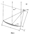
- Figure 6 illustrates the geometry of an antenna system according to one aspect of the present invention
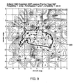
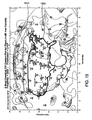
- Figures 7 to 9 depict EIRP contour plots at for an antenna system on a HIEO satellite at various angles of yaw according to various aspects of the present invention
- FIGS 10A and 10B illustrate an advantage in cross-polar isolation enjoyed by an antenna system according to one aspect of the present invention
- Figure 11 depicts a cross-polar isolation contour plot for an antenna system on a HIEO satellite according to one aspect of the present invention
- Figures 12 and 13 depict EIRP contour plots for an antenna system on a GEO satellite in various configurations according to various aspects of the present invention
- Figures 14 and 15 depict cross-polar isolation contour plots for an antenna system on a GEO satellite in various configurations according to various aspects of the present invention.
- Figure 16 is a flowchart depicting a method for generating and configuring at least one defocused beam according to another embodiment of the present invention.
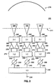
- FIG. 1 illustrates an antenna system for generating and configuring at least one defocused beam according to one embodiment of the present invention.
- Antenna system 100 includes a reflector 110 having a non-parabolic curvature for forming one or more defocused beams.
- a plurality of feed antennas 120 are disposed in the focal plane 111 of reflector 110. The feed antennas 120 illuminate reflector 110 to generate the one or more defocused beams in the following manner.
- An incoming signal 130 is divided by an incoming signal dividing network 140 into a plurality of sub-signals 145. Each sub signal 145 corresponds to one of the feed antennas 120. Each sub-signal 145 is received from incoming signal dividing network 140 by a variable phase shifter 150 which phase shifts sub-signal 145 to generate a corresponding phase-shifted sub-signal 155. A corresponding fixed-amplitude amplifier 160 amplifies each phase-shifted sub-signal 155 to generate an amplified phase-shifted sub-signal 165 which is provided to the corresponding feed antenna 120. Feed antennas 120 together illuminate reflector 110 with amplified phase-shifted sub-signals 165 to generate the one or more defocused beams.
- Amplifiers 160 are fixed-amplitude amplifiers. Accordingly, the configuration of the one or more beams is accomplished with phase-only synthesis, as is discussed in greater detail below.
- the use of fixed-amplitude amplifiers allows antenna system 100 to operate close to saturation with maximum DC-to-RF conversion efficiency (e.g ., about 60% efficiency).
- amplifiers 160 are traveling wave tube amplifiers ("TWTAs").
- amplifiers 160 may be solid state power amplifiers ("SSPAs”) or any other fixed-amplitude amplifiers.
- Reflector 110 has a non-parabolic curvature to form one or more defocused beams.
- the curvature of reflector 110 is optimized to minimize the number of elements (e.g ., amplifiers, feed antennas, etc.) in the feed array and to efficiency combine the individual beamlets (i.e ., the signals from each feed antenna 120).
- the curvature of reflector 110 is selected so that the resultant beam has a quadratic phase distribution in the aperture plane of reflector 110.
- This curvature broadens the one or more defocused beams to about 2 to 3 times the breadth that would be generated by a parabolic reflector, thereby reducing the required number of feed array elements by a factor of 4, as is discussed in greater detail below with respect to Figure 4 .
- reflector 110 is a 12 meter mesh reflector. According to other embodiments, reflector 110 may be any other size, and may be any other kind of reflector known to those of skill in the art. According to one embodiment, reflector 110 may include a single-axis gimbal mechanism (not illustrated) to provide ground track compensation for the rolling motion of a satellite vehicle on which antenna system 100 is deployed.
- variable phase shifters 150 are 8-bit phase shifters with the ability to adjust the phase of a signal in increments of 1.4°. According to other embodiments, variable phase shifters 150 may be any kind of phase shifter known to those of skill in the art. Post-amplification signal losses are kept low by phase shifting the sub-signals 145 with variable phase shifters 150 prior to amplification.
- incoming signal dividing network 140 is illustrated as a 1:3 network (i.e ., dividing incoming signal 130 into three sub-signals 145), the scope of the present invention is not limited to such an arrangement. Rather, an incoming signal dividing network of the present invention may divide an incoming signal into any number of sub-signals, corresponding to the number of feed antennas, as will be apparent to one of skill in the art. For example, in an embodiment in which the antenna system has 37 feed antennas, an incoming signal dividing network of the present invention will divide an incoming signal into 37 sub-signals.
- the amplification in antenna system 100 is distributed by providing feed antennas 120 with corresponding amplifiers 160. This distributed amplification mitigates the risk of multipaction. While in the present exemplary embodiment illustrated in Figure 1 , one amplifier 160 corresponds to each feed antenna 120, the scope of the present invention is not limited to such an arrangement. Rather, as will be apparent to one of skill in the art, an antenna system of the present invention may have more than one amplifier corresponding to each feed antenna, as is illustrated in greater detail with respect to Figure 2 .
- Antenna system 200 includes a reflector 210 having a non-parabolic curvature for forming one or more defocused beams.
- a plurality of feed antennas 220 are disposed in the focal plane 21 of reflector 210. The feed antennas 220 illuminate reflector 210 to generate the one or more defocused beams in the following manner.
- An incoming signal 230 is divided by an incoming signal dividing network 240 into a plurality of sub-signals 245.
- Each sub signal 245 corresponds to one of the feed antennas 220.
- Each sub-signal 245 is received from incoming signal dividing network 240 by a variable phase shifter 250 which phase shifts sub-signal 245 to generate a corresponding phase-shifted sub-signal 255.
- a corresponding pre-amp dividing network 270 divides each phase-shifted sub-signal 255 to generate a plurality of divided phase-shifted sub-signals 275.
- Each divided phase-shifted sub-signal 275 is provided to a corresponding fixed-amplitude amplifier 260.
- Each amplifier 260 amplifies the corresponding divided phase-shifted sub-signal 275 to generate an amplified divided phase-shifted sub-signal 265.
- a combining network 280 which receives the amplified divided phase-shifted sub-signals 265 from each amplifier in a group of amplifiers corresponding to one feed antenna 220 and combines them to generate a corresponding amplified phase-shifted sub-signal 285, which is provided to the corresponding feed antenna 220.
- Feed antennas 220 together illuminate reflector 210 with amplified phase-shifted sub-signals 285 to generate the one or more defocused beams.
- the RF power of an antenna system of the present invention depends upon the number of feed antennas provided and the number of amplifiers associated with each feed antenna. Accordingly, Table 1, below, illustrates various arrangements in which the number of feed antennas and the number of amplifiers associated with each feed antenna are varied to provide a different levels of RF power. For the purposes of the present exemplary embodiment of Table 1, each amplifier is assumed to be a 230W TWTA. Table 1 # of Feeds # Amps / Feed RF Power DC Power 32 1 7,360 12,475 16 2 7,360 12,475 37 1 8,510 14,424 20 2 9,200 15,593 48 1 1,1040 18,712
- each feed antenna 220 has two corresponding fixed-amplitude amplifiers 260.
- the scope of the present invention is not limited to such an arrangement, Rather, as will be apparent to one of skill in the art, the present invention has application to antenna systems in which any number of amplifiers corresponds to each feed antenna, including arrangements in which different numbers of amplifiers correspond to different feed antennas.
- Figure 3A illustrates a feed array 310 according to one aspect of the present invention in which one feed antenna 316 corresponds to two fixed-amplitude amplifiers 306 and 307, while other feed antennas 315 and 317 each correspond to one fixed-amplitude amplifier 305 and 308, respectively. If each amplifier 305, 306. 307 and 308 have the same amplitude, feed antenna 316 will provide a beamlet with twice the amplitude of feed antennas 315 and 317.
- FIG. 3B illustrates a feed array 320 according to another aspect of the present invention, in which fixed-amplitude amplifiers do not correspond to particular feed antennas.
- An incoming signal 321 is divided by an incoming signal dividing network 322 into a plurality of sub-signals 323.
- Each sub signal 323 corresponds to one of the feed antennas 349 and 350.
- Each sub-signal 323 is received from incoming signal dividing network 322 by a variable phase shifter 324 which phase shifts sub-signal 323 to generate a corresponding phase-shifted sub-signal 325.
- a redundancy ring with a plurality of fixed-amplitude amplifiers 326 amplifies phase-shifted sub-signals 325 and passes the amplified phase-shifted sub-signals 327 to couplers 328 and 329.
- each coupler 328 is a 2:1 coupler
- coupler 329 is a 32:1 coupler. Accordingly, feed antenna 350 will provide a beamlet with 16 times the amplitude of any of feed antennas 349.
- FIG. 3C illustrates a feed array 360 according to another aspect of the present invention, in which multiple incoming signals are provided to generate multiple beams.
- Each incoming signal 361 is divided by a corresponding incoming signal dividing network 362 to generate a corresponding plurality of sub-signals 363.
- Each sub signal 363 generated by a single incoming signal dividing network corresponds to one of the feed antennas 377.
- Each sub signal 363 is received from one of the incoming signal dividing networks 362 by a variable attenuator 364 and a variable phase shifter 365 which adjust the amplitude of sub-signal 363, and phase shift sub-signal 363, respectively, to generate a corresponding phase-shifted sub-signal 366.
- each incoming signal dividing network 362 is a combining network 367 which combines one phase-shifted sub-signal 366 corresponding to each incoming signal dividing network 362 to generate a combined phase-shifted sub-signal 368 corresponding to one of the feed antennas 377.
- the combined phase-shifted sub-signals 368 are received from combining networks 367 by an input hybrid matrix 369, which generates hybrid phase-shifted sub-signals 370.
- Each hybrid phase-shifted sub-signal 370 corresponds to one of the feed antennas 377.
- Each hybrid phase-shifted sub-signal 370 passes through redundancy input switch matrix 371 and is provided to a corresponding fixed-amplitude amplifier 372 which amplifies the corresponding hybrid phase-shifted sub-signal 370 to generate an amplified hybrid phase-shifted sub-signal 373.
- Amplified hybrid phase-shifted sub-signals 373 then pass through redundancy output switch matrix 374 and are received by an output hybrid matrix 375. which generates amplified phase-shifted sub-signals 376, which are provided to corresponding feed antennas 377.
- Feed antennas 377 together illuminate a non-focused reflector (not illustrated) to generate a plurality of defocused beams.
- Figure 4 illustrates a feed array 430 illuminating three different reflectors 410, 411 and 412.
- Feed array 430 is disposed in the focal plane (not shown) of all three reflectors 410, 411 and 412, although the angles in Figure 4 have been exaggerated for clarity.
- Reflector 411 is a parabolic reflector. Accordingly, the corresponding wavefront 421 in the aperture plane of reflector 411 has a uniform phase.
- Reflector 410 has been "opened up" with respect to parabolic reflector 411 (i.e ., the curvature of reflector 410 is less than that of reflector 411) such that the corresponding wavefront 420 in the aperture plane of reflector 410 has a quadratic phase distribution.
- a quadratic phase distribution significantly broadens the one or more beams formed by reflector 410, reducing the number of feed elements required to perform the necessary beam configurations by a factor of 4.
- reflector 412 has been "closed in” with respect to parabolic reflector 411 (i.e., the curvature of reflector 412 is greater than that of reflector 411) such that the corresponding wavefront 422 in the aperture plane of reflector 412 has a quadratic phase distribution.
- non-parabolic reflectors 410 and 412 in Figure 4 have been illustrated as possessing a curvature for generating a quadratic phase distribution in a wavefront at their respective aperture planes, the scope of the present invention is not limited to such an arrangement. Rather, the present invention has application to reflectors with any non-parabolic curvature to generate one or more de-focused beams.
- the feed arrays in the foregoing exemplary embodiments have been illustrated as including feed antennas arranged in a linear fashion, the scope of the present invention is not limited to such an arrangement. Rather, as will be apparent to one of skill in the art, the present invention has application to antenna systems in which the feed arrays include feed antennas in any arrangement.
- a feed array of the present invention may be arranged as a two-dimensional array.
- FIG 5A illustrates the arrangement of a feed array 500 suitable for use in a HIEO satellite according to one aspect of the present invention.
- Feed array 500 includes 37 feed antennas 501, each of which has the same amplitude of 238W.
- the uniform distribution of amplitude between the large number of feed antennas 501 provides the extensive on-orbit configurability need to compensate for the continual yawing of a HIEO satellite.
- Figure SB illustrates a feed array 510 including 7 feed antennas 511 and 512.
- Inner feed antenna 512 has a much larger amplitude ( i.e., 5,328 W) than the outer feed antennas 511 ( i.e ., 380 W).
- the amplitudes of feed antennas 511 and 512 are, as in Figure 5A , fixed amplitudes.
- This distribution of power among the feed antennas, in which the outer feed antennas 512 have about a - 11.5 dB taper relative to central feed antenna 511, is suitable for use in a GEO satellite, in which the required on-orbit configurability is not as extensive as in a HIEO satellite.
- Antenna system 600 includes non-parabolic reflector 610 and feed array 620 disposed in the focal plane 630 of reflector 610.
- Reflector 610 has a diameter D .
- Focal plane 630 is located a focal distance F from reflector 610.
- Feed array 620 is offset a height h from the edge of reflector 610.
- reflector 610 has a diameter D of 12.0 m and a focal distance F of 8.4m, providing a moderate F / D ratio of about 0.7.
- An antenna system of the present invention utilizes phase-only synthesis to configure (e.g., steer, shape, rotate, etc.) the one or more beams that it generates.
- phase-only synthesis e.g., steer, shape, rotate, etc.
- an antenna system of the present invention was mathematically modeled to illustrate the capability of phase-only synthesis to provide yaw compensation for a HIEO satellite with 50° of inclination and 12 hours of coverage over the continental United States (“CONUS").
- the antenna system of the present exemplary embodiment included 37 feed antennas with 0.24 m apertures and equal amplitudes of 238 W illuminating a 12.0 m non-parabolic reflector with a left-handed circularly polarized ("LHCP") signal in the S-Band (i.e., 2320.0 to 2332.5 MHz).
- LHCP left-handed circularly polarized
- FIGs 7 to 9 illustrate the Effective isotropically-radiated power ("EIRP") contour plots for this exemplary embodiment at each of 0°, 90° and 180° of yaw when the satellite is at apogee ( i.e ., 08:00 hr).
- EIRP Effective isotropically-radiated power
- the antenna system When the satellite on which the antenna system is yawed by 90°, the antenna system is able to compensate by reshaping the beam using phase-only synthesis, as can be seen with reference to Figure 8 , in which the CONUS 800 at 90° yaw is still provided with an EIRP of well over 60 dB. Even as the satellite yaws to 180°, the antenna system is able to compensate using phase-only synthesis, as can be seen with reference to Figure 9 , in which the CONUS 900 at 180° yaw is still provided with an EIRP of well over 60 dB.
- the phase-only synthesis allows the beam to cover the CONUS more efficiently, since less spill-over energy is expended outside of the desired coverage area.
- Table 2 illustrates the phase delays introduced by the variable phase shifters (i.e ., phase-only synthesis) at apogee for each of the 37 feed antennas in the antenna system of the present exemplary embodiment at each of 0°, 45°, 90°, 135° and 180° of yaw.
- each feed antenna was a constant -15.682 dB (supplied by a single 238 W fixed-amplitude amplifier per feed antenna).
- the beam configuration was accordingly provided solely by the phase shift introduced in each beamlet by the variable phase shifters.
- Figure 10B illustrates the phase distribution of the primary pattern of an antenna system according to one embodiment of the present invention, at each of 0° yaw (1030), 45° yaw (1031), 90° yaw (1032) and 135° yaw (1033).
- Figure 10A is a graph illustrating the cross-polar isolation of the primary pattern of the same antenna system.
- the difference between cross-polar directivity (1020 at 0° yaw, 1021 at 45° yaw, 1022 at 90° yaw, and 1023 at 135° yaw) and the co-polar directivity (1010 at 0° yaw, 101 at 45° yaw, 1012 at 90° yaw, and 1013 at 135° yaw) in the primary pattern is greater than 33 dB.
- This cross-polar isolation of greater than 33 dB in the primary pattern permits an antenna system of the present invention to enjoy high gain and directivity, regardless of the phase distribution of the feed array.
- FIG. 11 a cross-polar isolation contour plot for this exemplary embodiment at 0° of yaw when the satellite is at apogee (i.e., 08:00 hr) is illustrated.
- the antenna system is able to generate a beam providing better than 30 dB cross-polar isolation for the CONUS 1100.
- an antenna system of the present invention was mathematically modeled to illustrate the capability of phase-only synthesis to provide on-orbit beam reconfiguration for a GEO satellite with an orbital arc of 94° to 98° west.
- the antenna-system of the present exemplary embodiment included 7 feed antennas with 0.37 m apertures and a fixed power distribution (i.e., a central feed of 24x222 W and 6 outer feeds of 2x190 W) illuminating a 12.0 m non-parabolic shaped reflector with a left-handed circularly polarized ("LHCP") signal in the S-Band (i.e., 2320.0 to 2332.5 MHz).
- LHCP left-handed circularly polarized
- the primary pattern cross-polar isolation was shown to be better than 40 dB, with a feed efficiency of greater than 85% and a multipaction margin for 9 KW peak power of 6.5 dB.
- Figures 12 and 13 illustrate the EIRP contour plots for this exemplary embodiment at 96° W for a baseline configuration and for a configuration in which an additional 1 dB more EIRP is provided to Canada.
- the antenna system is able to generate a beam providing an EIRP of well over 64 dB for the CONUS 1200.
- the antenna system is able to reconfigure the beam to provide an additional 1 dB of EIRP to Canada 1310 while still providing over 64 dB for the CONUS 1300.
- Figure 14 illustrates a cross-polar isolation contour plot for the baseline configuration of this exemplary embodiment at 96° W.
- the antenna system is able to generate a beam providing a cross-polar isolation of better than 36 dB for substantially all of the CONUS 1400.
- Figure 15 when the antenna system is reconfigured through phase-only synthesis to provide an additional 1 dB of EIRP to Canada 1510, the cross-polar isolation over the CONUS 1500 and substantially all of Canada 1510 remains better than 36 dB.
- Table 3 illustrates the phase delays introduced by the variable phase shifters (i.e ., phase-only synthesis) for each of the 7 feed antennas in the antenna system of the present exemplary embodiment in the baseline configuration and to provide an additional 1° dB of EIRP to Canada.
- Table 3 Element Amplitude (dB) Phase (deg) Baseline +1 dB over Canada 1 -1.551 0.0 0.0 2 -13.006 0.0 3.77 3 -13.006 0.0 -1.55 4 -13.006 0.0 -1.31 5 -13.006 0.0 . -2.23 6 -13.006 0.0 -5.07 7 -13.006 0.0 -9.28
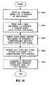
- FIG. 16 is a flowchart illustrating a method for generating and configuring at least one defocused beam using an antenna system with a non-parabolic reflector and an array of feed antennas according to one embodiment of the present invention.
- the array of feed antennas is disposed in the focal plane of the non-parabolic reflector.
- an incoming signal is divided into a plurality of sub signals using an incoming signal dividing network. Each sub-signal corresponds to one of the feed antennas in the feed array.
- each of the sub-signals is phase-shifted, using a variable phase shifter, to generate a corresponding phase-shifted sub-signal.
- each of the phase-shifted sub-signals is amplified by one or more amplifiers to generate an amplified phase-shifted sub-signal.
- each phase-shifted sub-signal will first be divided by a corresponding pre-amp dividing network to generate a plurality of divided phase-shifted sub-signals, which, after amplification, will be combined in a combining network.
- each amplified phase-shifted sub-signal generated in step 1630 is provided to the corresponding feed antenna which, in step 1650, illuminates the non-parabolic reflector to generate at least one defocused beam.
Landscapes
- Aerials With Secondary Devices (AREA)
- Variable-Direction Aerials And Aerial Arrays (AREA)
Claims (18)
- Antennensystem (100; 200; 600) zum Erzeugen und Konfigurieren wenigstens eines nicht-fokussierten Strahls, wobei das Antennensystem (100; 200; 600) umfasst:einen Reflektor (110; 210; 410; 412; 610) mit einer Brennebene (111; 211; 630) und einer nicht-parabolischen Krümmung, die den wenigstens einen nicht-fokussierten Strahl bildet;eine Vielzahl von Speiseantennen (120; 220; 377; 501, 511, 512), die den Reflektor (110; 210; 410; 412; 610) beleuchten, wobei jede Speiseantenne (120; 220; 377; 501, 511, 512) in der Brennebene (111; 211; 630) des Reflektors (110; 210; 410; 412; 610) angeordnet ist;wenigstens ein Netzwerk (140; 240; 322; 362) zum Trennen ankommender Signale, das wenigstens ein ankommendes Signal (130; 230; 321; 361) in eine Vielzahl von Teilsignalen (145; 245; 323; 363) trennt, wobei jedes Teilsignal (145; 245; 323; 363) einer der Vielzahl von Speiseantennen (120; 220; 377; 501, 511, 512) entspricht;gekennzeichnet durcheine Vielzahl variabler Phasenschieber (150; 250; 324; 365), wobei jeder variable Phasenschieber (150; 250; 324; 365) eines der Vielzahl von Teilsignalen (145; 245; 323; 363) von dem wenigstens einen Netzwerk (140; 240; 322; 362) zum Trennen ankommender Signale empfängt und das eine der Vielzahl von Teilsignalen (145; 245; 323; 363) phasenverschiebt, um ein entsprechendes phasenverschobenes Teilsignal (255; 325; 366) zu erzeugen;eine Vielzahl von Verstärkern (160; 260; 306; 307; 326) mit fester Amplitude, wobei wenigstens ein Verstärker jeder der Vielzahl von Speiseantennen (120; 220; 377; 501, 511, 512) entspricht, wobei der wenigstens eine Verstärker für jede Speiseantenne (120; 220; 377; 501, 511, 512) das entsprechende phasenverschobene Teilsignal (255; 325; 366) verstärkt, um ein verstärktes phasenverschobenes Teilsignal (265; 327) zu erzeugen, das an die entsprechende Speiseantenne (120; 220; 377; 501, 511, 512) geliefert wird,wobei die Krümmung des Reflektors (110; 210; 410; 412; 610) eine symmetrische quadratische Phasenfront in einer Aperturebene des Reflektors (110; 210; 410; 412; 610) erzeugt.
- Antennensystem (100; 200; 600) nach Anspruch 1, wobei wenigstens zwei Verstärker jeder der Vielzahl von Speiseantennen (120; 220; 377; 501, 511, 512) entsprechen, wobei das Antennensystem (100; 200; 600) ferner umfasst:eine Vielzahl von Vorverstärker-Trennnetzwerken, wobei jedes Vorverstärker-Trennnetzwerk einem der Vielzahl von phasenverschobenen Teilsignalen (255; 325; 366) entspricht, wobei jedes Vorverstärker-Trennnetzwerk das entsprechende phasenverschobene Teilsignal in eine Vielzahl getrennter phasenverschobener Teilsignale (275) trennt und jedes phasenverschobene Teilsignal an einen entsprechenden der wenigstens zwei Verstärker bereitstellt; undeine Vielzahl von Kombinationsnetzwerken, wobei jedes Kombinationsnetzwerk einem der Vielzahl von Vorverstärker-Trennnetzwerken entspricht, wobei jedes Kombinationsnetzwerk eine Vielzahl von verstärkten getrennten phasenverschobenen Teilsignalen (275), die von den wenigstens zwei Verstärkern empfangen werden, zu einem entsprechenden verstärkten phasenverschobenen Teilsignal (265) kombiniert und das verstärkte phasenverschobene Teilsignal an die entsprechende Speiseantenne (120; 220; 377; 501, 511, 512) liefert.
- Antennensystem (100; 200; 600) nach Anspruch 1, wobei das wenigstens eine ankommende Signal (130; 230; 321; 361) eine Vielzahl von ankommenden Signalen umfasst, und wobei das wenigstens eine Netzwerk (140; 240; 322; 362) zum Trennen ankommender Signale eine entsprechende Vielzahl von Netzwerken (140; 240; 322; 362) zum Trennen ankommender Signale umfasst, wobei das Antennensystem (100; 200; 600) ferner umfasst:eine Vielzahl von Kombinationsnetzwerken, wobei jedes Kombinationsnetzwerk einem der Vielzahl von Netzwerken (140; 240; 322; 362) zum Trennen ankommender Signale entspricht, wobei jedes Kombinationsnetzwerk ein entsprechendes der Vielzahl der phasenverschobenen Teilsignale (255; 325; 366), die von einer entsprechenden Vielzahl der variablen Phasenschieber empfangen werden, kombiniert, um ein kombiniertes phasenverschobenes Teilsignal (368) zu erzeugen;eine hybride Eingangsmatrix, die die Vielzahl kombinierter phasenverschobener Teilsignale (368) von der Vielzahl von Kombinationsnetzwerken empfängt, eine entsprechende Vielzahl von hybriden phasenverschobenen Teilsignalen (370) erzeugt und jedes der Vielzahl von hybriden phasenverschobenen Teilsignalen an einen entsprechenden der Vielzahl von Verstärkern (160; 260; 306; 307; 326) mit fester Amplitude liefert, der das hybride phasenverschobene Teilsignal (370) verstärkt, um ein entsprechendes verstärktes hybrides phasenverschobenes Teilsignal (373) zu erzeugen; undeine hybride Ausgangsmatrix, die die verstärkten hybriden phasenverschobenen Teilsignale (373) von der Vielzahl von Verstärkern (160; 260; 306; 307; 326) mit fester Amplitude empfängt, eine entsprechende Vielzahl von verstärkten phasenverschobenen Teilsignalen (376) erzeugt und jedes verstärkte phasenverschobene Teilsignal an eine entsprechende der Vielzahl von Speiseantennen (120; 220; 377; 501, 511, 512) liefert.
- Antennensystem (100; 200; 600) nach Anspruch 1, wobei der wenigstens eine Verstärker, der jeder der Vielzahl von Speiseantennen (120; 220; 377; 501, 511, 512) entspricht, eine gleiche Anzahl von Verstärkern umfasst, die jeder der Vielzahl von Speiseantennen (120; 220; 377; 501, 511, 512) entsprechen.
- Antennensystem (100; 200; 600) nach Anspruch 1, wobei jedes verstärkte phasenverschobene Teilsignal die gleiche Amplitude wie jedes andere verstärkte phasenverschobene Teilsignal hat.
- Antennensystem (100; 200; 600) nach Anspruch 1, wobei die Vielzahl von variablen Phasenschiebern (150; 250; 324; 365) die Vielzahl von Teilsignalen (145; 245; 245; 323; 363) phasenverschiebt, um eine Form oder eine Richtung des wenigstens einen nicht-fokussierten Strahls zu modifizieren.
- Antennensystem (100; 200; 600) nach Anspruch 1, wobei die Vielzahl von Speiseantennen (120; 220; 377; 501, 511, 512) in einer Anordnung in der Brennebene (111; 211; 630) des Reflektors (110; 210; 410; 412; 610) angeordnet sind, und wobei die Speiseantennen (120; 220; 377; 501, 511, 512), die näher an einer Mitte der Anordnung angeordnet sind, den Reflektor (110; 210; 410; 412; 610) mit Signalen höherer Amplitude beleuchten als die Speiseantennen (120; 220; 377; 501, 511, 512), die weiter weg von der Mitte der Anordnung angeordnet sind.
- Antennensystem (100; 200; 600) nach Anspruch 1, wobei der Reflektor (110; 210; 410; 412; 610) einen Einachsen-Kardanaufhängungsmechanismus umfasst.
- Satellit, der das Antennensystem (100; 200; 600) nach Anspruch 1 enthält, wobei die Vielzahl variabler Phasenschieber (150; 250; 324; 365) die Vielzahl von Teilsignalen (145; 245; 323; 363) phasenverschieben, um eine Giergegenkompensation für den wenigstens einen nicht-fokussierten Strahl bereitzustellen.
- Verfahren zum Erzeugen und Konfigurieren wenigstens eines nicht-fokussierten Strahls unter Verwendung eines Antennensystems (100; 200; 600), das einen Reflektor (110; 210; 410; 412; 610) mit einer nicht-parabolischen Krümmung und eine Vielzahl von Speiseantennen (120; 220; 377; 501, 511, 512), die in einer Brennebene (111; 211; 630) des Reflektors (110; 210; 410; 412; 610) angeordnet sind, umfasst, wobei das Verfahren die folgenden Schritte umfasst:Trennen wenigstens eines ankommenden Signals (130; 230; 321; 361) mit wenigstens einem Netzwerk (140; 240; 322; 362) zum Trennen ankommender Signale in eine Vielzahl von Teilsignalen (145; 245; 323; 363), wobei jedes Teilsignal (145; 245; 323; 363) einer der Vielzahl von Speiseantennen (120; 220; 377; 501, 511, 512) entspricht;Phasenverschieben von Teilsignalen (145; 245; 323; 363) mit einer Vielzahl von variablen Phasenschiebern (150; 250; 324; 365), wobei jeder variable Phasenschieber (150; 250; 324; 365) eines der Vielzahl von Teilsignalen (145; 245; 323; 363) von dem wenigstens einen Netzwerk (140; 240; 322; 362) zum Trennen ankommender Signale empfängt und das eine der Vielzahl von Teilsignalen (145; 245; 323; 363) phasenverschiebt, um ein entsprechendes phasenverschobenes Teilsignal (145; 245; 323; 363) zu erzeugen;Verstärken der Vielzahl von phasenverschobenen Teilsignalen mit einer Vielzahl von Verstärkern (160; 260; 306; 307; 326) mit fester Amplitude, wobei wenigstens ein Verstärker jeder der Vielzahl von Speiseantennen (120; 220; 377; 501, 511, 512) entspricht, wobei der wenigstens eine Verstärker für jede Speiseantenne (120; 220; 377; 501, 511, 512) ein entsprechendes phasenverschobenes Teilsignal verstärkt, um ein verstärktes phasenverschobenes Teilsignal zu erzeugen, das an die entsprechende Speiseantenne (120; 220; 377; 501, 511, 512) geliefert wird; undBeleuchten des Reflektors (110; 210; 410; 412; 610) mit der Vielzahl von Speiseantennen (120; 220; 377; 501, 511, 512), um den wenigstens einen nicht-fokussierten Strahl zu erzeugen, wobei die Krümmung des Reflektors (110; 210; 410; 412; 610) eine symmetrische quadratische Phasenfront in einer Aperturebene des Reflektors (110; 210; 410; 412; 610) erzeugt.
- Verfahren nach Anspruch 10, wobei wenigstens zwei Verstärker jeder der Vielzahl von Speiseantennen (120; 220; 377; 501, 511, 512) entsprechen, wobei das Verfahren ferner die folgenden Schritte umfasst:Trennen des entsprechenden phasenverschobenen Teilsignales in eine Vielzahl von getrennten phasenverschobenen Teilsignalen in einer Vielzahl von Vorverstärker-Trennnetzwerken, wobei jedes Vorverstärker-Trennnetzwerk einem der Vielzahl von phasenverschobenen Teilsignalen entspricht;Bereitstellen jedes geteilten phasenverschobenen Teilsignals an einen entsprechenden der wenigstens zwei Verstärker; undKombinieren einer Vielzahl von verstärkten getrennten phasenverschobenen Teilsignalen, die von den wenigstens zwei Verstärkern empfangen werden, in einer Vielzahl von Kombinationsnetzwerken, wobei jedes Kombinationsnetzwerk einem der Vielzahl von Vorverstärker-Trennnetzwerken entspricht, und Bereitstellen des verstärkten phasenverschobenen Teilsignals an die entsprechende Speiseantenne (120; 220; 377; 501, 511, 512).
- Verfahren nach Anspruch 10, wobei das wenigstens eine ankommende Signal (130; 230; 321; 361) eine Vielzahl von ankommenden Signalen umfasst, und wobei das wenigstens eine Netzwerk (140; 240; 322; 362) zum Trennen ankommender Signale eine entsprechende Vielzahl von Netzwerken (140; 240; 322; 362) zum Trennen ankommender Signale umfasst, wobei das Verfahren ferner die folgenden Schritte umfasst:Kombinieren einer entsprechenden Vielzahl der phasenverschobenen Teilsignale, die von einem entsprechenden Vielzahl der variablen Phasenschieber empfangen werden, mit einer Vielzahl von Kombinationsnetzwerken, um ein kombiniertes phasenverschobenes Teilsignal zu erzeugen, wobei jedes Kombinationsnetzwerk einem der Vielzahl von Netzwerken zum Trennen ankommender Signale entspricht;Bereitstellen der Vielzahl kombinierter phasenverschobener Teilsignale von der Vielzahl von Kombinationsnetzwerken an eine hybride Eingangsmatrix, die eine entsprechende Vielzahl von hybriden phasenverschobenen Teilsignalen erzeugt und jedes der Vielzahl von hybriden phasenverschobenen Teilsignalen an einen entsprechenden der Vielzahl von Verstärkern (160; 260; 306; 307; 326) mit fester Amplitude liefert, der das hybride phasenverschobene Teilsignal verstärkt, um ein entsprechendes verstärktes hybrides phasenverschobenes Teilsignal zu erzeugen; undBereitstellen der verstärkten hybriden phasenverschobenen Teilsignale an eine hybride Ausgangsmatrix, die eine entsprechende Vielzahl von verstärkten phasenverschobenen Teilsignalen erzeugt und jedes verstärkte phasenverschobene Teilsignal an eine entsprechende der Vielzahl von Speiseantennen (120; 220; 377; 501, 511, 512) liefert.
- Verfahren nach Anspruch 10, wobei der wenigstens eine Verstärker, der jeder der Vielzahl von Speiseantennen (120; 220; 377; 501, 511, 512) entspricht, eine gleiche Anzahl von Verstärkern umfasst, die jeder der Vielzahl von Speiseantennen (120; 220; 377; 501, 511, 512) entsprechen.
- Verfahren nach Anspruch 10, wobei jedes verstärkte phasenverschobene Teilsignal die gleiche Amplitude wie jedes andere verstärkte phasenverschobene Teilsignal hat.
- Verfahren nach Anspruch 10, wobei die Vielzahl von variablen Phasenschiebern (150; 250; 324; 365) die Vielzahl von Teilsignalen (145; 245; 323; 363) phasenverschiebt, um eine Form oder eine Richtung des wenigstens einen nicht-fokussierten Strahls zu modifizieren.
- Verfahren nach Anspruch 10, wobei die Vielzahl von Speiseantennen (120; 220; 377; 501, 511, 512) in einer Anordnung in der Brennebene (111; 211; 630) des Reflektors (110; 210; 410; 412; 610) angeordnet sind, und wobei die Speiseantennen (120; 220; 377; 501, 511, 512), die näher an einer Mitte der Anordnung angeordnet sind, den Reflektor (110; 210; 410; 412; 610) mit Signalen höherer Amplitude beleuchten als die Speiseantennen (120; 220; 377; 501, 511, 512), die weiter weg von der Mitte der Anordnung angeordnet sind.
- Verfahren nach Anspruch 10, wobei der Reflektor (110; 210; 410; 412; 610) einen Einachsen-Kardanaufhängungsmechanismus umfasst.
- Verfahren nach Anspruch 17,
wobei die Vielzahl variabler Phasenschieber (150; 250; 324; 365) die Vielzahl von Teilsignalen (145; 245; 323; 363) phasenverschieben, um eine Gierbewegung des Antennensystems (100; 200; 600) zu kompensieren, und
wobei der Einachsen-Kardanaufhängungsmechanismus des Reflektors (110; 210; 410; 412; 610) den Reflektor (110; 210; 410; 412; 610) kardanisch aufhängt, um eine Rollbewegung des Antennensystems (100; 200; 600) zu kompensieren.
Applications Claiming Priority (3)
| Application Number | Priority Date | Filing Date | Title |
|---|---|---|---|
| US75867406P | 2006-01-13 | 2006-01-13 | |
| US11/480,497 US7710340B2 (en) | 2006-01-13 | 2006-07-05 | Reconfigurable payload using non-focused reflector antenna for HIEO and GEO satellites |
| PCT/US2006/047609 WO2007087038A2 (en) | 2006-01-13 | 2006-12-14 | Reconfigurable payload using non-focused reflector antenna for hieo and geo satellites |
Publications (3)
| Publication Number | Publication Date |
|---|---|
| EP1972030A2 EP1972030A2 (de) | 2008-09-24 |
| EP1972030A4 EP1972030A4 (de) | 2010-11-24 |
| EP1972030B1 true EP1972030B1 (de) | 2012-11-21 |
Family
ID=38309700
Family Applications (1)
| Application Number | Title | Priority Date | Filing Date |
|---|---|---|---|
| EP06845366A Active EP1972030B1 (de) | 2006-01-13 | 2006-12-14 | Umkonfigurierbare nutzinformationen unter verwendung einer nichtfokussierten reflektorantenne für hieo- und geo-satelliten |
Country Status (3)
| Country | Link |
|---|---|
| US (1) | US7710340B2 (de) |
| EP (1) | EP1972030B1 (de) |
| WO (1) | WO2007087038A2 (de) |
Families Citing this family (13)
| Publication number | Priority date | Publication date | Assignee | Title |
|---|---|---|---|---|
| US8354956B2 (en) * | 2006-01-13 | 2013-01-15 | Lockheed Martin Corporation | Space segment payload architecture for mobile satellite services (MSS) systems |
| EP2528159A3 (de) * | 2007-03-16 | 2013-02-13 | Mobile SAT Ltd. | Verfahren zum Kommunizieren per Satellit |
| WO2011056255A1 (en) * | 2009-11-06 | 2011-05-12 | Viasat, Inc. | Electromechanical polarization switch |
| KR102087793B1 (ko) * | 2013-07-05 | 2020-04-14 | 한국전자통신연구원 | 다중 빔 안테나 시스템 및 이의 출력 전력 제어 방법 |
| US9373896B2 (en) * | 2013-09-05 | 2016-06-21 | Viasat, Inc | True time delay compensation in wideband phased array fed reflector antenna systems |
| US10122085B2 (en) * | 2014-12-15 | 2018-11-06 | The Boeing Company | Feed re-pointing technique for multiple shaped beams reflector antennas |
| US9590299B2 (en) | 2015-06-15 | 2017-03-07 | Northrop Grumman Systems Corporation | Integrated antenna and RF payload for low-cost inter-satellite links using super-elliptical antenna aperture with single axis gimbal |
| CN107196684B (zh) * | 2017-03-27 | 2020-11-06 | 上海华为技术有限公司 | 一种天线系统、信号处理系统以及信号处理方法 |
| AU2017409520B2 (en) | 2017-04-10 | 2022-03-17 | Viasat, Inc. | Coverage area adjustment to adapt satellite communications |
| US10516216B2 (en) | 2018-01-12 | 2019-12-24 | Eagle Technology, Llc | Deployable reflector antenna system |
| US10707552B2 (en) | 2018-08-21 | 2020-07-07 | Eagle Technology, Llc | Folded rib truss structure for reflector antenna with zero over stretch |
| US10587055B1 (en) * | 2019-07-08 | 2020-03-10 | Northrop Grumman Systems Corporation | Imaging reflector antenna system and method |
| JP7029202B1 (ja) | 2021-05-27 | 2022-03-03 | 国立研究開発法人宇宙航空研究開発機構 | アンテナ、電子機器およびアンテナの製造方法 |
Family Cites Families (9)
| Publication number | Priority date | Publication date | Assignee | Title |
|---|---|---|---|---|
| FR2652452B1 (fr) * | 1989-09-26 | 1992-03-20 | Europ Agence Spatiale | Dispositif d'alimentation d'une antenne a faisceaux multiples. |
| US5422595A (en) * | 1993-11-24 | 1995-06-06 | Sgs-Thomson Microelectronics, Inc. | Miniature, low cost power amplifier monitor |
| US5936588A (en) | 1998-06-05 | 1999-08-10 | Rao; Sudhakar K. | Reconfigurable multiple beam satellite phased array antenna |
| US5936592A (en) * | 1998-06-05 | 1999-08-10 | Ramanujam; Parthasarathy | Reconfigurable multiple beam satellite reflector antenna with an array feed |
| FR2811480B1 (fr) * | 2000-07-06 | 2006-09-08 | Cit Alcatel | Antenne de telecommunication destinee a couvrir une large zone terrestre |
| US6456252B1 (en) * | 2000-10-23 | 2002-09-24 | The Boeing Company | Phase-only reconfigurable multi-feed reflector antenna for shaped beams |
| US6943745B2 (en) * | 2003-03-31 | 2005-09-13 | The Boeing Company | Beam reconfiguration method and apparatus for satellite antennas |
| US7034771B2 (en) * | 2003-09-10 | 2006-04-25 | The Boeing Company | Multi-beam and multi-band antenna system for communication satellites |
| KR100579129B1 (ko) * | 2003-12-26 | 2006-05-12 | 한국전자통신연구원 | 성형 반사판을 이용한 오프셋 하이브리드 안테나 |
-
2006
- 2006-07-05 US US11/480,497 patent/US7710340B2/en active Active
- 2006-12-14 EP EP06845366A patent/EP1972030B1/de active Active
- 2006-12-14 WO PCT/US2006/047609 patent/WO2007087038A2/en not_active Ceased
Also Published As
| Publication number | Publication date |
|---|---|
| EP1972030A2 (de) | 2008-09-24 |
| US7710340B2 (en) | 2010-05-04 |
| WO2007087038A2 (en) | 2007-08-02 |
| US20070182654A1 (en) | 2007-08-09 |
| WO2007087038A3 (en) | 2008-01-10 |
| EP1972030A4 (de) | 2010-11-24 |
Similar Documents
| Publication | Publication Date | Title |
|---|---|---|
| EP0963006B1 (de) | Phasengesteuerte Satellitengruppenantenne mit rekonfigurierbaren Mehrfachstrahlungskeulen | |
| US5151706A (en) | Apparatus for electronically controlling the radiation pattern of an antenna having one or more beams of variable width and/or direction | |
| US6456252B1 (en) | Phase-only reconfigurable multi-feed reflector antenna for shaped beams | |
| US8354956B2 (en) | Space segment payload architecture for mobile satellite services (MSS) systems | |
| US6366256B1 (en) | Multi-beam reflector antenna system with a simple beamforming network | |
| US6456251B1 (en) | Reconfigurable antenna system | |
| US5115248A (en) | Multibeam antenna feed device | |
| US5936592A (en) | Reconfigurable multiple beam satellite reflector antenna with an array feed | |
| US6246364B1 (en) | Light-weight modular low-level reconfigurable beamformer for array antennas | |
| US9356358B2 (en) | Architectures and methods for novel antenna radiation optimization via feed repositioning | |
| US6943745B2 (en) | Beam reconfiguration method and apparatus for satellite antennas | |
| US6429823B1 (en) | Horn reflect array | |
| EP1972030B1 (de) | Umkonfigurierbare nutzinformationen unter verwendung einer nichtfokussierten reflektorantenne für hieo- und geo-satelliten | |
| US4965588A (en) | Electronically scanned antenna | |
| US11699850B2 (en) | Method and apparatus for beam steering and switching | |
| JP2000216627A (ja) | 隣接した高利得アンテナ・ビ―ムを供給するコンパクト・オフセット・グレゴリオ型アンテナ装置 | |
| EP1119072B1 (de) | Antennengruppenkonfiguration für Weitwinkel-Überdeckung | |
| WO2021236204A2 (en) | Reconfigurable, flexible multi-user electrically steered antenna (esa) terminal | |
| EP3272028B1 (de) | Rekonfigurierbare hf-frontend-schaltung für ein durch mehrstrahl-array gespeistes reflektorantennensystem | |
| JPH1093337A (ja) | マルチビームアンテナ | |
| JPH10229308A (ja) | ビーム走査アンテナ装置 | |
| Angeletti et al. | Antennas for broadband and mobile satellite communications | |
| Rao et al. | Common aperture satellite antenna system for multiple contoured beams and multiple spot beams | |
| Greenwood et al. | Multimatrix beamforming for semi-active antennas at L-band | |
| Suzuki et al. | Beam Forming for Large-Scale Phased Array Antennas |
Legal Events
| Date | Code | Title | Description |
|---|---|---|---|
| PUAI | Public reference made under article 153(3) epc to a published international application that has entered the european phase |
Free format text: ORIGINAL CODE: 0009012 |
|
| 17P | Request for examination filed |
Effective date: 20080618 |
|
| AK | Designated contracting states |
Kind code of ref document: A2 Designated state(s): FR |
|
| DAX | Request for extension of the european patent (deleted) | ||
| RBV | Designated contracting states (corrected) |
Designated state(s): FR |
|
| A4 | Supplementary search report drawn up and despatched |
Effective date: 20101027 |
|
| RIC1 | Information provided on ipc code assigned before grant |
Ipc: H01Q 19/12 20060101ALI20101021BHEP Ipc: H01Q 19/10 20060101ALI20101021BHEP Ipc: H01Q 19/17 20060101ALI20101021BHEP Ipc: H01Q 13/00 20060101AFI20070910BHEP |
|
| GRAP | Despatch of communication of intention to grant a patent |
Free format text: ORIGINAL CODE: EPIDOSNIGR1 |
|
| RIC1 | Information provided on ipc code assigned before grant |
Ipc: H01Q 25/00 20060101ALI20120627BHEP Ipc: H01Q 19/17 20060101ALI20120627BHEP Ipc: H01Q 19/10 20060101ALI20120627BHEP Ipc: H01Q 19/12 20060101ALI20120627BHEP Ipc: H01Q 13/00 20060101AFI20120627BHEP |
|
| GRAS | Grant fee paid |
Free format text: ORIGINAL CODE: EPIDOSNIGR3 |
|
| GRAA | (expected) grant |
Free format text: ORIGINAL CODE: 0009210 |
|
| AK | Designated contracting states |
Kind code of ref document: B1 Designated state(s): FR |
|
| PLBE | No opposition filed within time limit |
Free format text: ORIGINAL CODE: 0009261 |
|
| STAA | Information on the status of an ep patent application or granted ep patent |
Free format text: STATUS: NO OPPOSITION FILED WITHIN TIME LIMIT |
|
| 26N | No opposition filed |
Effective date: 20130822 |
|
| REG | Reference to a national code |
Ref country code: FR Ref legal event code: PLFP Year of fee payment: 10 |
|
| REG | Reference to a national code |
Ref country code: FR Ref legal event code: PLFP Year of fee payment: 11 |
|
| REG | Reference to a national code |
Ref country code: FR Ref legal event code: PLFP Year of fee payment: 12 |
|
| PGFP | Annual fee paid to national office [announced via postgrant information from national office to epo] |
Ref country code: FR Payment date: 20241226 Year of fee payment: 19 |