EP1970876A1 - Dispositif de fixation d'un écran plat sur un simulateur de véhicule - Google Patents
Dispositif de fixation d'un écran plat sur un simulateur de véhicule Download PDFInfo
- Publication number
- EP1970876A1 EP1970876A1 EP08290217A EP08290217A EP1970876A1 EP 1970876 A1 EP1970876 A1 EP 1970876A1 EP 08290217 A EP08290217 A EP 08290217A EP 08290217 A EP08290217 A EP 08290217A EP 1970876 A1 EP1970876 A1 EP 1970876A1
- Authority
- EP
- European Patent Office
- Prior art keywords
- screen
- simulator
- support
- observation device
- frame
- Prior art date
- Legal status (The legal status is an assumption and is not a legal conclusion. Google has not performed a legal analysis and makes no representation as to the accuracy of the status listed.)
- Granted
Links
Images

Classifications
-
- G—PHYSICS
- G09—EDUCATION; CRYPTOGRAPHY; DISPLAY; ADVERTISING; SEALS
- G09B—EDUCATIONAL OR DEMONSTRATION APPLIANCES; APPLIANCES FOR TEACHING, OR COMMUNICATING WITH, THE BLIND, DEAF OR MUTE; MODELS; PLANETARIA; GLOBES; MAPS; DIAGRAMS
- G09B9/00—Simulators for teaching or training purposes
- G09B9/02—Simulators for teaching or training purposes for teaching control of vehicles or other craft
- G09B9/04—Simulators for teaching or training purposes for teaching control of vehicles or other craft for teaching control of land vehicles
- G09B9/05—Simulators for teaching or training purposes for teaching control of vehicles or other craft for teaching control of land vehicles the view from a vehicle being simulated
-
- B—PERFORMING OPERATIONS; TRANSPORTING
- B60—VEHICLES IN GENERAL
- B60R—VEHICLES, VEHICLE FITTINGS, OR VEHICLE PARTS, NOT OTHERWISE PROVIDED FOR
- B60R11/00—Arrangements for holding or mounting articles, not otherwise provided for
- B60R11/02—Arrangements for holding or mounting articles, not otherwise provided for for radio sets, television sets, telephones, or the like; Arrangement of controls thereof
- B60R11/0229—Arrangements for holding or mounting articles, not otherwise provided for for radio sets, television sets, telephones, or the like; Arrangement of controls thereof for displays, e.g. cathodic tubes
- B60R11/0235—Arrangements for holding or mounting articles, not otherwise provided for for radio sets, television sets, telephones, or the like; Arrangement of controls thereof for displays, e.g. cathodic tubes of flat type, e.g. LCD
-
- F—MECHANICAL ENGINEERING; LIGHTING; HEATING; WEAPONS; BLASTING
- F16—ENGINEERING ELEMENTS AND UNITS; GENERAL MEASURES FOR PRODUCING AND MAINTAINING EFFECTIVE FUNCTIONING OF MACHINES OR INSTALLATIONS; THERMAL INSULATION IN GENERAL
- F16M—FRAMES, CASINGS OR BEDS OF ENGINES, MACHINES OR APPARATUS, NOT SPECIFIC TO ENGINES, MACHINES OR APPARATUS PROVIDED FOR ELSEWHERE; STANDS; SUPPORTS
- F16M11/00—Stands or trestles as supports for apparatus or articles placed thereon ; Stands for scientific apparatus such as gravitational force meters
- F16M11/20—Undercarriages with or without wheels
- F16M11/22—Undercarriages with or without wheels with approximately constant height, e.g. with constant length of column or of legs
-
- G—PHYSICS
- G09—EDUCATION; CRYPTOGRAPHY; DISPLAY; ADVERTISING; SEALS
- G09B—EDUCATIONAL OR DEMONSTRATION APPLIANCES; APPLIANCES FOR TEACHING, OR COMMUNICATING WITH, THE BLIND, DEAF OR MUTE; MODELS; PLANETARIA; GLOBES; MAPS; DIAGRAMS
- G09B9/00—Simulators for teaching or training purposes
- G09B9/003—Simulators for teaching or training purposes for military purposes and tactics
-
- G—PHYSICS
- G09—EDUCATION; CRYPTOGRAPHY; DISPLAY; ADVERTISING; SEALS
- G09B—EDUCATIONAL OR DEMONSTRATION APPLIANCES; APPLIANCES FOR TEACHING, OR COMMUNICATING WITH, THE BLIND, DEAF OR MUTE; MODELS; PLANETARIA; GLOBES; MAPS; DIAGRAMS
- G09B9/00—Simulators for teaching or training purposes
- G09B9/02—Simulators for teaching or training purposes for teaching control of vehicles or other craft
- G09B9/04—Simulators for teaching or training purposes for teaching control of vehicles or other craft for teaching control of land vehicles
Definitions
- the technical sector of the present invention is that of simulators and in particular armored vehicle simulators.
- Vehicle simulators are widely used for learning to drive and use vehicles (aircraft cabin, military vehicles, railway vehicles, ). The use of such simulators has the advantage of being more economical and less dangerous than the actual use of vehicles.
- These simulators use screens (or monitors) to give a vision of the environment that is proposed to the user as part of the simulation. These screens are observed through openings such as episcopes or optical tunnels. In general, there is the problem of adapting the screen to the simulator and that of its positioning relative to the observation aperture (optical tunnel).
- cathode screens It is known to use cathode screens.
- the latter have a relatively large mass which ensures their stability with respect to the structure of the simulator. Moreover they are generally arranged near the openings which facilitates visibility and limits light loss.
- the object of the present invention is therefore to provide a device for fixing a flat screen on a simulator does not have the aforementioned drawbacks.
- the invention therefore relates to a device for fixing a flat screen on a vehicle simulator comprising a support structure integral with the simulator and a screen support now rigidly attached to the screen, intended to be fixed on the support structure in order to positioning the screen facing an observation device integrated in the simulator, characterized in that the screen support comprises a frame disposed at the front of the screen and having lateral wings extending on either side of the screen, a rear support adapted to be fixed on the standard rear attachment of the screen and an adjustable connection means between the front frame and the rear support to allow the adaptation of the screen support to different thicknesses of the screen. 'screen.
- the device comprises lateral flanges integral with the support structure and adjustable connection means between the side flanges and the lateral wings of the frame.
- the lateral wings have oblong holes for positioning the height of the screen relative to the support structure.
- the rear support comprises a wedging means intended to constitute a support for the rear surface of the screen.
- the device comprises an optical connector intended to be arranged between the screen and the simulator observation device.
- the optical connector is fixed to the front frame and mounted so sliding in the extension of the simulator observation device.
- the device comprises retractable indexing fingers integral with the simulator observation device and making it possible to adjust in depth the position of the screen relative to the observation device of the simulator. simulator.
- An advantage of the device according to the invention lies in the secure fixing of the screen.
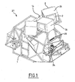
- the figure 1 represents a cabin of a simulator as already known, provided with conventional screens.
- Vehicle simulators are conventionally made by a cabin 27 around which is disposed a carrier structure 1 for receiving screens 26.
- a drive device 24 ensures the movement of the cabin to simulate the vehicle movements.
- Monitors 26, of the cathode-ray screen type are arranged in front of observation devices (for example episcopes or optical tunnels) enabling the person inside the simulator to view a simulated situation.
- the screens 26 being subjected to the movements of the cabin, they are rigidly fixed to the structure 1 by means of lateral flanges 2.
- the structure 1 also comprises sources While such an embodiment is suitable for cathode-ray tube screens, it does not allow LCD-type (liquid crystal) screens which are much lighter to be powered.
- the figure 2 represents a device for fixing a flat screen 4 on a vehicle simulator according to the invention.
- the device according to the invention comprises a carrier structure 1 integral with the simulator and a screen support now rigidly the screen 4 and intended to be fixed on the carrier structure 1 in order to position the screen 4 facing an observation device 14 integrated in the simulator.
- the screen support is made by a frame 3 and a rear support 7.
- the frame 3 is disposed at the front of the screen 4 and has side wings 6 extending on either side of the screen 4.
- the rear support 7 is adapted to be attached to the rear of the screen 4 according to a method of attachment which will be described later.
- the frame 3 and the rear support 7 are interconnected in an adjustable manner to allow the adaptation of the screen support to different thicknesses of screens.
- the supporting structure 1 comprises lateral flanges 2 on which the screen support is adjustably fixed. Braces 5 ensure the rigidity and the maintenance in vertical position of the lateral flanges 2.
- the figure 3 illustrates more particularly the adjustable connection means between the frame 3 and the rear support 7 and between the frame 3 and the lateral flanges 2.
- the lateral wings 6 have horizontal oblong holes 9 in which screws 13 integral with the rear support 7 are inserted.
- the screws 13 cooperate with the horizontal oblong holes 9 in order to constitute a connecting means.
- the lateral wings 6 also have vertical oblong holes 10 in which screws 12 are inserted for cooperating with the side flanges 2 (not shown in this figure).
- the screw 12 and vertical oblong holes 10 therefore constitute an adjustable connection means for positioning the height of the frame 3 relative to the flanges (and thus allowing the positioning of the screen 4 in height relative to the supporting structure 1).
- the lateral wings 6 comprise bosses 11 (also having vertical oblong holes) making it possible to secure the flanges and the lateral wings 6 while maintaining a space allowing the passage of the screws 13 and their nut 21.
- the rear support 7 comprises a wedging means 8 (here rubber studs) intended to form a support for the rear surface of the screen 4 (not shown).
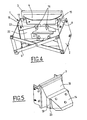
- the figure 4 is a rear view of the device according to the invention illustrating more particularly the method of fixing the screen 4 on the rear support 7.
- the rear support 7 is formed by a main plate 22 and two side plates 15. Reinforcements 23 provide the rigidity of the support.
- the side plates 15 are intended to cooperate with the lateral wings 6 of the frame 3, as described above.
- the rear face 17 of the screen 4 bears against the main plate 22 of the rear support 7.
- Screws 16 provide the rigid connection of the rear support 7 and the screen 4.
- the screens available in the trade have at the rear face 17, standard fasteners.
- the rear support 7 is therefore adapted to be fixed on the standard rear attachment of the screen 4.
- the figure 5 illustrates an embodiment of an optical connector disposed between the screen and an observation device.
- the optical connector 18 is intended to be disposed between the screen 4 and the observation device 14 of the simulator.
- a first end of the optical connector 18 is fixed on the front frame 3 and substantially matches the shape of the frame 3.
- the second end 19 of the optical connector is slidably mounted in the extension 20 of the observation device 14 of the simulator.
- the optical connection 18 and / or the frame 3 retractable indexing fingers for fixing the relative position of the screen 4 relative to the observation device 14 of the simulator.
- the indexing fingers may be adjustable to ensure the depth adjustment of the position of the screen 4 relative to the observation device 14 of the simulator.
Landscapes
- Engineering & Computer Science (AREA)
- Theoretical Computer Science (AREA)
- General Physics & Mathematics (AREA)
- Business, Economics & Management (AREA)
- Physics & Mathematics (AREA)
- Educational Administration (AREA)
- Educational Technology (AREA)
- Aviation & Aerospace Engineering (AREA)
- Mechanical Engineering (AREA)
- General Engineering & Computer Science (AREA)
- Devices For Indicating Variable Information By Combining Individual Elements (AREA)
- Overhead Projectors And Projection Screens (AREA)
- Fittings On The Vehicle Exterior For Carrying Loads, And Devices For Holding Or Mounting Articles (AREA)
- Automobile Manufacture Line, Endless Track Vehicle, Trailer (AREA)
Abstract
Description
- Le secteur technique de la présente invention est celui des simulateurs et en particulier des simulateurs d'engins blindés.
- Les simulateurs de véhicule sont largement utilisés pour l'apprentissage de la conduite et de l'utilisation de véhicules (cabine d'avion, véhicules militaires, véhicules ferroviaires,...). L'utilisation de tels simulateurs présente l'avantage d'être plus économique et moins dangereuse que l'utilisation réelle des véhicules. Ces simulateurs utilisent des écrans (ou moniteurs) permettant de donner une vision de l'environnement qui est proposé à l'utilisateur dans le cadre de la simulation. Ces écrans sont observés au travers d'ouvertures telles que des épiscopes ou des tunnels optiques. Il se pose d'une manière générale le problème de l'adaptation de l'écran sur le simulateur et celui de son positionnement par rapport à l'ouverture d'observation (tunnel optique).
- Il est connu de mettre en oeuvre des écrans cathodiques. Ces derniers présentent une masse relativement importante qui assure leur stabilité par rapport à la structure du simulateur. Par ailleurs ils sont généralement disposés à proximité des ouvertures ce qui facilite la visibilité et limite les pertes de lumière.
- Compte tenu des évolutions techniques des composants, les écrans cathodiques doivent maintenant être remplacés par des écrans plats type LCD (cristaux liquides) ou plasma. Cependant ces écrans ont une masse plus réduite et sont plus sensibles aux vibrations que leur communique le simulateur. Les moyens de fixation standard connus (plaque à l'arrière de l'écran) qui permettent de lier un écran à un support (par exemple un pied) sont inadaptés à la fixation sur un simulateur car ils n'assurent pas la rigidité suffisante de l'écran par rapport au simulateur.
- Par ailleurs il est nécessaire de pouvoir régler le positionnement de ces écrans par rapport au simulateur pour éviter toute déformation de l'image pour l'utilisateur. Il est enfin maintenant nécessaire de positionner les écrans à une distance des ouvertures qui est plus importante qu'auparavant (en raison de l'amélioration de la qualité des vues diffusées par les écrans). Il se pose donc aussi le problème d'assurer la diffusion de la lumière fournie par l'écran en évitant les perturbations provoquées par la lumière extérieure.
- Le but de la présente invention est donc de fournir un dispositif de fixation d'un écran plat sur un simulateur ne présentant pas les inconvénients précédemment mentionnés.
- L'invention a donc pour objet un dispositif de fixation d'un écran plat sur un simulateur de véhicule comportant une structure porteuse solidaire du simulateur et un support d'écran maintenant rigidement l'écran, destiné à être fixé sur la structure porteuse afin de positionner l'écran face à un dispositif d'observation intégré au simulateur, caractérisé en ce que le support d'écran comporte un cadre disposé à l'avant de l'écran et présentant des ailes latérales s'étendant de part et d'autre de l'écran, un support arrière adapté à être fixé sur la fixation standard arrière de l'écran et un moyen de liaison réglable entre le cadre avant et le support arrière afin de permettre l'adaptation du support d'écran à différentes épaisseurs d'écran.
- Selon une caractéristique de l'invention, le dispositif comporte des flasques latérales solidaires de la structure porteuse et des moyens de liaison réglables entre les flasques latérales et les ailes latérales du cadre.
- Selon une autre caractéristique de l'invention, les ailes latérales présentent des trous oblongs permettant le positionnement en hauteur de l'écran par rapport à la structure porteuse.
- Selon encore une autre caractéristique de l'invention, le support arrière comporte un moyen de calage destiné à constituer un appui pour la surface arrière de l'écran.
- Selon une autre caractéristique de l'invention, le dispositif comporte un raccord optique destiné à être disposé entre l'écran et le dispositif d'observation du simulateur.
- Selon une autre caractéristique de l'invention, le raccord optique est fixé sur le cadre avant et monté de façon glissante dans le prolongement du dispositif d'observation du simulateur.
- Selon une autre caractéristique de l'invention, le dispositif comporte des doigts d'indexage rétractables solidaires du dispositif d'observation du simulateur et permettant d'assurer le réglage en profondeur de la position de l'écran par rapport au dispositif d'observation du simulateur.
- Un avantage du dispositif selon l'invention réside dans la fixation sécurisée de l'écran.
- D'autres caractéristiques, détails et avantages de l'invention ressortiront plus clairement de la description donnée ci-après à titre indicatif en relation avec des dessins dans lesquels :
- la
figure 1 représente une cabine d'un simulateur telle que déjà connue, - la
figure 2 est une vue en perspective d'un dispositif selon l'invention, - la
figure 3 illustre plus particulièrement les moyens de liaison réglables de l'invention, - la
figure 4 est une vue arrière d'un dispositif selon l'invention, et - la
figure 5 illustre un raccord optique disposé entre l'écran et un dispositif d'observation. - La
figure 1 représente une cabine d'un simulateur telle que déjà connue, munie d'écrans classiques. - Les simulateurs de véhicule sont classiquement réalisés par une cabine 27 autour de laquelle est disposée une structure porteuse 1 destinée à recevoir des écrans 26. Un dispositif de motorisation 24 assure la mise en mouvement de la cabine afin de simuler les mouvements du véhicule. Des moniteurs 26, du type écrans cathodiques sont disposés face à des dispositifs d'observation (par exemple des épiscopes ou des tunnels optiques) permettant à la personne à l'intérieur du simulateur de visionner une situation simulée. Les écrans 26 étant soumis aux mouvements de la cabine, ils sont rigidement fixés à la structure 1 au moyen de flasques latérales 2. La structure 1 comporte également des sources d'alimentation électriques permettant la mise sous tension des écrans 26. Si une telle réalisation est adaptée à des écrans à tube cathodique, elle ne permet pas de recevoir des écrans du type LCD (à cristaux liquide) qui sont beaucoup plus légers.
- La
figure 2 représente un dispositif de fixation d'un écran plat 4 sur un simulateur de véhicule selon l'invention. Le dispositif selon l'invention comporte une structure porteuse 1 solidaire du simulateur et un support d'écran maintenant rigidement l'écran 4 et destiné à être fixé sur la structure porteuse 1 afin de positionner l'écran 4 face à un dispositif d'observation 14 intégré au simulateur. Le support d'écran est réalisé par un cadre 3 et un support arrière 7. Le cadre 3 est disposé à l'avant de l'écran 4 et présente des ailes latérales 6 s'étendant de part et d'autre de l'écran 4. Le support arrière 7 est adapté à être fixé à l'arrière de l'écran 4 selon un mode de fixation qui sera décrit par la suite. Le cadre 3 et le support arrière 7 sont reliés entre eux de manière réglable afin de permettre l'adaptation du support d'écran à différentes épaisseurs d'écrans. La structure porteuse 1 comporte des flasques latérales 2 sur lesquelles est fixé de manière réglable le support d'écran. Des croisillons 5 assurent la rigidité et le maintien en position verticale des flasques latérales 2. - La
figure 3 illustre plus particulièrement les moyens de liaison réglables entre le cadre 3 et le support arrière 7 et entre le cadre 3 et les flasques latérales 2. - On peut notamment distinguer sur cette figure que les ailes latérales 6 présentent des trous oblongs horizontaux 9 dans lesquels s'insèrent des vis 13 solidaires du support arrière 7. Ainsi les vis 13 coopèrent avec les trous oblongs horizontaux 9 afin de constituer un moyen de liaison à positionnement réglable entre le cadre avant 3 et le support arrière 7 permettant l'adaptation du support d'écran à différentes épaisseurs d'écrans. Les ailes latérales 6 présentent également des trous oblongs verticaux 10 dans lesquels s'insèrent des vis 12 destinées à coopérer avec les flasques latérales 2 (non représentées sur cette figure). Les vis 12 et les trous oblongs verticaux 10 constituent donc un moyen de liaison réglable permettant le positionnement en hauteur du cadre 3 par rapport aux flasques (et permettant ainsi le positionnement en hauteur de l'écran 4 par rapport à la structure porteuse 1). On remarquera que les ailes latérales 6 comportent des bossages 11 (comportant également des trous oblongs verticaux) permettant de solidariser les flasques et les ailes latérales 6 tout en conservant un espace permettant le passage des vis 13 et de leur écrou 21.
- On peut également distinguer que le support arrière 7 comporte un moyen de calage 8 (ici des plots en caoutchouc) destiné à constituer un appui pour la surface arrière de l'écran 4 (non représenté).
- La
figure 4 est une vue arrière du dispositif selon l'invention illustrant plus particulièrement le mode de fixation de l'écran 4 sur le support arrière 7. Le support arrière 7 est réalisé par une plaque principale 22 et deux plaques latérales 15. Des renforts 23 assurent la rigidité du support. Les plaques latérales 15 sont destinées à coopérer avec les ailes latérales 6 du cadre 3, comme décrit précédemment. La face arrière 17 de l'écran 4 vient en appui contre la plaque principale 22 du support arrière 7. Des vis 16 assurent la liaison rigide du support arrière 7 et de l'écran 4. D'une manière générale les écrans disponibles dans le commerce comportent au niveau de la face arrière 17, des fixations standard. Le support arrière 7 est donc adapté à être fixé sur la fixation standard arrière de l'écran 4. - La
figure 5 illustre un mode de réalisation d'un raccord optique disposé entre l'écran et un dispositif d'observation. - Le raccord optique 18 est destiné à être disposé entre l'écran 4 et le dispositif d'observation 14 du simulateur. A cet effet, une première extrémité du raccord optique 18 est fixée sur le cadre avant 3 et épouse sensiblement la forme du cadre 3. La seconde extrémité 19 du raccord optique est montée de façon glissante dans le prolongement 20 du dispositif d'observation 14 du simulateur.
- Afin de pouvoir positionner l'écran par rapport au dispositif d'observation 14, on pourra équiper le dispositif d'observation 14, le raccord optique 18 et/ou le cadre 3 de doigts d'indexage rétractables permettant de fixer la position relative de l'écran 4 par rapport au dispositif d'observation 14 du simulateur. Les doigts d'indexage pourront être réglables pour assurer le réglage en profondeur de la position de l'écran 4 par rapport au dispositif d'observation 14 du simulateur.
Claims (7)
- Dispositif de fixation d'un écran plat sur un simulateur de véhicule comportant une structure porteuse (1) solidaire du simulateur et un support d'écran maintenant rigidement l'écran (4), destiné à être fixé sur la structure porteuse (1) afin de positionner l'écran (4) face à un dispositif d'observation (14) intégré au simulateur, caractérisé en ce que le support d'écran comporte un cadre (3) disposé à l'avant de l'écran (4) et présentant des ailes latérales (6) s'étendant de part et d'autre de l'écran (4), un support arrière (7) adapté à être fixé sur la fixation standard arrière de l'écran (4) et un moyen (9,13) de liaison réglable entre le cadre avant (3) et le support arrière (7) afin de permettre l'adaptation du support d'écran à différentes épaisseurs d'écran.
- Dispositif selon la revendication 1, caractérisé en ce qu'il comporte des flasques latérales (2) solidaires de la structure porteuse (1) et des moyens (10,12) de liaison réglables entre les flasques latérales (2) et les ailes latérales (6) du cadre (3).
- Dispositif selon la revendication 2, caractérisé en ce que les ailes latérales (6) présentent des trous oblongs (10) permettant le positionnement en hauteur de l'écran (4) par rapport à la structure porteuse (1).
- Dispositif selon l'une des revendications 1 à 3, caractérisé en ce que le support arrière (7) comporte un moyen de calage (8) destiné à constituer un appui pour la surface arrière de l'écran (4).
- Dispositif selon l'une des revendications 1 à 4, caractérisé en ce qu'il comporte un raccord optique (18) destiné à être disposé entre l'écran (4) et le dispositif d'observation (14) du simulateur.
- Dispositif selon la revendication 5, caractérisé en ce que le raccord optique (18) est fixé sur le cadre avant (3) et monté de façon glissante dans le prolongement (20) du dispositif d'observation (14) du simulateur.
- Dispositif selon la revendication 5 ou 6, caractérisé en ce qu'il comporte des doigts d'indexage rétractables solidaires du dispositif d'observation (14) du simulateur et permettant d'assurer le réglage en profondeur de la position de l'écran (4) par rapport au dispositif d'observation (14) du simulateur.
Applications Claiming Priority (1)
| Application Number | Priority Date | Filing Date | Title |
|---|---|---|---|
| FR0701816A FR2913801B1 (fr) | 2007-03-14 | 2007-03-14 | Dispositif de fixation d'un ecran plat sur un simulateur de vehicule |
Publications (2)
| Publication Number | Publication Date |
|---|---|
| EP1970876A1 true EP1970876A1 (fr) | 2008-09-17 |
| EP1970876B1 EP1970876B1 (fr) | 2010-06-02 |
Family
ID=38476038
Family Applications (1)
| Application Number | Title | Priority Date | Filing Date |
|---|---|---|---|
| EP08290217A Active EP1970876B1 (fr) | 2007-03-14 | 2008-03-06 | Dispositif de fixation d'un écran plat sur un simulateur de véhicule |
Country Status (4)
| Country | Link |
|---|---|
| EP (1) | EP1970876B1 (fr) |
| AT (1) | ATE470210T1 (fr) |
| DE (1) | DE602008001393D1 (fr) |
| FR (1) | FR2913801B1 (fr) |
Citations (6)
| Publication number | Priority date | Publication date | Assignee | Title |
|---|---|---|---|---|
| EP0872819A1 (fr) | 1997-04-14 | 1998-10-21 | Lockheed Martin Corporation | Simulateurs d'entraínement |
| EP0942221A1 (fr) * | 1998-03-09 | 1999-09-15 | Krauss-Maffei Wegmann GmbH & Co. KG | Console déplacable de maintien d'un appareil, en particulier un écran de l'intérieur d'un véhicule, en particulier un véhicule de combat |
| WO2003003106A1 (fr) * | 2001-06-28 | 2003-01-09 | Siemens Aktiengesellschaft | Dispositif de retenue permettant un montage flottant d'un ecran plat et dispositif d'affichage electronique comprenant un ecran plat et un dispositif de retenue |
| WO2003010645A2 (fr) * | 2001-07-25 | 2003-02-06 | Intergraph Hardware Technologies Company | Systeme informatique et moniteur renforces et localement isoles |
| US20040029094A1 (en) * | 2002-08-06 | 2004-02-12 | Mcgraw Robert W. | Reconfigurable simulation structure |
| US20060076463A1 (en) * | 2004-10-13 | 2006-04-13 | Drew Paul L | Flat panel display mounting apparatuses |
-
2007
- 2007-03-14 FR FR0701816A patent/FR2913801B1/fr not_active Expired - Fee Related
-
2008
- 2008-03-06 DE DE602008001393T patent/DE602008001393D1/de active Active
- 2008-03-06 AT AT08290217T patent/ATE470210T1/de not_active IP Right Cessation
- 2008-03-06 EP EP08290217A patent/EP1970876B1/fr active Active
Patent Citations (6)
| Publication number | Priority date | Publication date | Assignee | Title |
|---|---|---|---|---|
| EP0872819A1 (fr) | 1997-04-14 | 1998-10-21 | Lockheed Martin Corporation | Simulateurs d'entraínement |
| EP0942221A1 (fr) * | 1998-03-09 | 1999-09-15 | Krauss-Maffei Wegmann GmbH & Co. KG | Console déplacable de maintien d'un appareil, en particulier un écran de l'intérieur d'un véhicule, en particulier un véhicule de combat |
| WO2003003106A1 (fr) * | 2001-06-28 | 2003-01-09 | Siemens Aktiengesellschaft | Dispositif de retenue permettant un montage flottant d'un ecran plat et dispositif d'affichage electronique comprenant un ecran plat et un dispositif de retenue |
| WO2003010645A2 (fr) * | 2001-07-25 | 2003-02-06 | Intergraph Hardware Technologies Company | Systeme informatique et moniteur renforces et localement isoles |
| US20040029094A1 (en) * | 2002-08-06 | 2004-02-12 | Mcgraw Robert W. | Reconfigurable simulation structure |
| US20060076463A1 (en) * | 2004-10-13 | 2006-04-13 | Drew Paul L | Flat panel display mounting apparatuses |
Non-Patent Citations (2)
| Title |
|---|
| MARIO MAZA: "SYMUSYS", 22 December 2005 (2005-12-22), pages 1 - 1, XP002452230, Retrieved from the Internet <URL:http://web.archive.org/web/20051222013928/http://laimuz.unizar.es/simusys/images/imghard_1h.jpg> [retrieved on 20070924] * |
| XMOTION: "XMOTION - ELECTRONIC & SOFTWARE DESIGN FOR DYNAMICS SOLUTIONS", 20 February 2007 (2007-02-20), pages 1 - 1, XP002452229, Retrieved from the Internet <URL:http://web.archive.org/web/20070220101046/http://www.xmotion.it/> [retrieved on 20070924] * |
Also Published As
| Publication number | Publication date |
|---|---|
| FR2913801A1 (fr) | 2008-09-19 |
| DE602008001393D1 (de) | 2010-07-15 |
| ATE470210T1 (de) | 2010-06-15 |
| FR2913801B1 (fr) | 2009-06-05 |
| EP1970876B1 (fr) | 2010-06-02 |
Similar Documents
| Publication | Publication Date | Title |
|---|---|---|
| FR2864013A1 (fr) | Ensemble de partie avant de vehicule automobile comportant des moyens perfectionnes de fixation et d'ajustement en position, et vehicule automobile pourvu d'un tel ensemble. | |
| EP2488379A1 (fr) | Cadre moteur pour moteur electrique de vehicule automobile | |
| FR2981318A1 (fr) | Support de projecteur pour vehicule automobile et projecteur correspondant | |
| EP1970876B1 (fr) | Dispositif de fixation d'un écran plat sur un simulateur de véhicule | |
| FR3019507A1 (fr) | Agencement pour maintenir un appareil multimedia nomade dans un vehicule | |
| FR3040027A1 (fr) | Systeme d'attache d'un appareil portable a un retroviseur interieur sans vis ni boutons pour s'ajuster a la dimension du retroviseur | |
| WO2021058894A1 (fr) | Pièce d'assemblage pour connecter une planche de bord à une partie de caisse d'un véhicule | |
| US20200156450A1 (en) | Adjustable fixture for a cover plate of a pickup truck | |
| FR2559278A1 (fr) | Collimateur de pilotage du type tete-haute | |
| FR3093069A1 (fr) | Dispositif de fixation d’un élément de protection sous moteur | |
| JP4536099B2 (ja) | テレビボード | |
| EP3152079A1 (fr) | Dispositif d'affichage destiné à l'habitacle d'un véhicule automobile | |
| FR3010465A1 (fr) | Dispositif de fixation amovible d’un composant de vehicule automobile | |
| EP2746089B1 (fr) | Support de boîtier d'affichage escamotable dans un véhicule et véhicule correspondant | |
| FR2944769A3 (fr) | Plot de fixation pour radiateur de vehicule automobile | |
| FR2960493A1 (fr) | Appui-tete et dispositif de montage d'accessoires sur ledit appui -tete | |
| FR2976646A1 (fr) | Dispositif de support d'un appareil d'affichage et procede de montage de l'appareil dans le dispositif | |
| FR3063818A1 (fr) | Dispositif d'affichage tete haute | |
| EP3146378B1 (fr) | Dispositif de support d'une lame semi-réfléchissante amovible pour un afficheur tête haute | |
| FR3079182A1 (fr) | Support de fixation etage pour boitiers electroniques destine a etre monte dans la partie laterale d’un coffre de vehicule automobile. | |
| EP4380820B1 (fr) | Module lumineux destiné à être fixé à un dispositif lumineux de véhicule automobile | |
| US9791698B2 (en) | Apparatus for providing a heads up display using a display output of a mobile device | |
| EP4610104B1 (fr) | Système de fixation amovible d'un écran sur un tableau de bord d'un aéronef, et système de visualisation comprenant un tel système de fixation | |
| FR3034880A1 (fr) | Dispositif portatif de visualisation | |
| FR3093066B1 (fr) | Système de carénage d’un essieu de véhicule automobile |
Legal Events
| Date | Code | Title | Description |
|---|---|---|---|
| PUAI | Public reference made under article 153(3) epc to a published international application that has entered the european phase |
Free format text: ORIGINAL CODE: 0009012 |
|
| AK | Designated contracting states |
Kind code of ref document: A1 Designated state(s): AT BE BG CH CY CZ DE DK EE ES FI FR GB GR HR HU IE IS IT LI LT LU LV MC MT NL NO PL PT RO SE SI SK TR |
|
| AX | Request for extension of the european patent |
Extension state: AL BA MK RS |
|
| 17P | Request for examination filed |
Effective date: 20090314 |
|
| 17Q | First examination report despatched |
Effective date: 20090417 |
|
| AKX | Designation fees paid |
Designated state(s): AT BE BG CH CY CZ DE DK EE ES FI FR GB GR HR HU IE IS IT LI LT LU LV MC MT NL NO PL PT RO SE SI SK TR |
|
| GRAP | Despatch of communication of intention to grant a patent |
Free format text: ORIGINAL CODE: EPIDOSNIGR1 |
|
| GRAS | Grant fee paid |
Free format text: ORIGINAL CODE: EPIDOSNIGR3 |
|
| GRAA | (expected) grant |
Free format text: ORIGINAL CODE: 0009210 |
|
| AK | Designated contracting states |
Kind code of ref document: B1 Designated state(s): AT BE BG CH CY CZ DE DK EE ES FI FR GB GR HR HU IE IS IT LI LT LU LV MC MT NL NO PL PT RO SE SI SK TR |
|
| REG | Reference to a national code |
Ref country code: GB Ref legal event code: FG4D Free format text: NOT ENGLISH |
|
| REG | Reference to a national code |
Ref country code: CH Ref legal event code: EP |
|
| REG | Reference to a national code |
Ref country code: IE Ref legal event code: FG4D Free format text: LANGUAGE OF EP DOCUMENT: FRENCH |
|
| REF | Corresponds to: |
Ref document number: 602008001393 Country of ref document: DE Date of ref document: 20100715 Kind code of ref document: P |
|
| REG | Reference to a national code |
Ref country code: CH Ref legal event code: NV Representative=s name: ING. MARCO ZARDI C/O M. ZARDI & CO. S.A. |
|
| REG | Reference to a national code |
Ref country code: NL Ref legal event code: VDEP Effective date: 20100602 |
|
| PG25 | Lapsed in a contracting state [announced via postgrant information from national office to epo] |
Ref country code: SE Free format text: LAPSE BECAUSE OF FAILURE TO SUBMIT A TRANSLATION OF THE DESCRIPTION OR TO PAY THE FEE WITHIN THE PRESCRIBED TIME-LIMIT Effective date: 20100602 Ref country code: LT Free format text: LAPSE BECAUSE OF FAILURE TO SUBMIT A TRANSLATION OF THE DESCRIPTION OR TO PAY THE FEE WITHIN THE PRESCRIBED TIME-LIMIT Effective date: 20100602 Ref country code: NO Free format text: LAPSE BECAUSE OF FAILURE TO SUBMIT A TRANSLATION OF THE DESCRIPTION OR TO PAY THE FEE WITHIN THE PRESCRIBED TIME-LIMIT Effective date: 20100902 |
|
| LTIE | Lt: invalidation of european patent or patent extension |
Effective date: 20100602 |
|
| PG25 | Lapsed in a contracting state [announced via postgrant information from national office to epo] |
Ref country code: LV Free format text: LAPSE BECAUSE OF FAILURE TO SUBMIT A TRANSLATION OF THE DESCRIPTION OR TO PAY THE FEE WITHIN THE PRESCRIBED TIME-LIMIT Effective date: 20100602 Ref country code: SI Free format text: LAPSE BECAUSE OF FAILURE TO SUBMIT A TRANSLATION OF THE DESCRIPTION OR TO PAY THE FEE WITHIN THE PRESCRIBED TIME-LIMIT Effective date: 20100602 Ref country code: AT Free format text: LAPSE BECAUSE OF FAILURE TO SUBMIT A TRANSLATION OF THE DESCRIPTION OR TO PAY THE FEE WITHIN THE PRESCRIBED TIME-LIMIT Effective date: 20100602 Ref country code: FI Free format text: LAPSE BECAUSE OF FAILURE TO SUBMIT A TRANSLATION OF THE DESCRIPTION OR TO PAY THE FEE WITHIN THE PRESCRIBED TIME-LIMIT Effective date: 20100602 Ref country code: HR Free format text: LAPSE BECAUSE OF FAILURE TO SUBMIT A TRANSLATION OF THE DESCRIPTION OR TO PAY THE FEE WITHIN THE PRESCRIBED TIME-LIMIT Effective date: 20100602 |
|
| PG25 | Lapsed in a contracting state [announced via postgrant information from national office to epo] |
Ref country code: PL Free format text: LAPSE BECAUSE OF FAILURE TO SUBMIT A TRANSLATION OF THE DESCRIPTION OR TO PAY THE FEE WITHIN THE PRESCRIBED TIME-LIMIT Effective date: 20100602 Ref country code: CY Free format text: LAPSE BECAUSE OF FAILURE TO SUBMIT A TRANSLATION OF THE DESCRIPTION OR TO PAY THE FEE WITHIN THE PRESCRIBED TIME-LIMIT Effective date: 20100602 |
|
| REG | Reference to a national code |
Ref country code: IE Ref legal event code: FD4D |
|
| PG25 | Lapsed in a contracting state [announced via postgrant information from national office to epo] |
Ref country code: IE Free format text: LAPSE BECAUSE OF FAILURE TO SUBMIT A TRANSLATION OF THE DESCRIPTION OR TO PAY THE FEE WITHIN THE PRESCRIBED TIME-LIMIT Effective date: 20100602 Ref country code: EE Free format text: LAPSE BECAUSE OF FAILURE TO SUBMIT A TRANSLATION OF THE DESCRIPTION OR TO PAY THE FEE WITHIN THE PRESCRIBED TIME-LIMIT Effective date: 20100602 Ref country code: NL Free format text: LAPSE BECAUSE OF FAILURE TO SUBMIT A TRANSLATION OF THE DESCRIPTION OR TO PAY THE FEE WITHIN THE PRESCRIBED TIME-LIMIT Effective date: 20100602 |
|
| PG25 | Lapsed in a contracting state [announced via postgrant information from national office to epo] |
Ref country code: IS Free format text: LAPSE BECAUSE OF FAILURE TO SUBMIT A TRANSLATION OF THE DESCRIPTION OR TO PAY THE FEE WITHIN THE PRESCRIBED TIME-LIMIT Effective date: 20101002 Ref country code: RO Free format text: LAPSE BECAUSE OF FAILURE TO SUBMIT A TRANSLATION OF THE DESCRIPTION OR TO PAY THE FEE WITHIN THE PRESCRIBED TIME-LIMIT Effective date: 20100602 Ref country code: CZ Free format text: LAPSE BECAUSE OF FAILURE TO SUBMIT A TRANSLATION OF THE DESCRIPTION OR TO PAY THE FEE WITHIN THE PRESCRIBED TIME-LIMIT Effective date: 20100602 Ref country code: SK Free format text: LAPSE BECAUSE OF FAILURE TO SUBMIT A TRANSLATION OF THE DESCRIPTION OR TO PAY THE FEE WITHIN THE PRESCRIBED TIME-LIMIT Effective date: 20100602 |
|
| PG25 | Lapsed in a contracting state [announced via postgrant information from national office to epo] |
Ref country code: IT Free format text: LAPSE BECAUSE OF FAILURE TO SUBMIT A TRANSLATION OF THE DESCRIPTION OR TO PAY THE FEE WITHIN THE PRESCRIBED TIME-LIMIT Effective date: 20100602 |
|
| PLBE | No opposition filed within time limit |
Free format text: ORIGINAL CODE: 0009261 |
|
| STAA | Information on the status of an ep patent application or granted ep patent |
Free format text: STATUS: NO OPPOSITION FILED WITHIN TIME LIMIT |
|
| PG25 | Lapsed in a contracting state [announced via postgrant information from national office to epo] |
Ref country code: DK Free format text: LAPSE BECAUSE OF FAILURE TO SUBMIT A TRANSLATION OF THE DESCRIPTION OR TO PAY THE FEE WITHIN THE PRESCRIBED TIME-LIMIT Effective date: 20100602 |
|
| 26N | No opposition filed |
Effective date: 20110303 |
|
| PG25 | Lapsed in a contracting state [announced via postgrant information from national office to epo] |
Ref country code: GR Free format text: LAPSE BECAUSE OF FAILURE TO SUBMIT A TRANSLATION OF THE DESCRIPTION OR TO PAY THE FEE WITHIN THE PRESCRIBED TIME-LIMIT Effective date: 20100903 |
|
| REG | Reference to a national code |
Ref country code: DE Ref legal event code: R097 Ref document number: 602008001393 Country of ref document: DE Effective date: 20110302 |
|
| BERE | Be: lapsed |
Owner name: NEXTER SYSTEMS Effective date: 20110331 |
|
| PG25 | Lapsed in a contracting state [announced via postgrant information from national office to epo] |
Ref country code: MC Free format text: LAPSE BECAUSE OF NON-PAYMENT OF DUE FEES Effective date: 20110331 |
|
| PG25 | Lapsed in a contracting state [announced via postgrant information from national office to epo] |
Ref country code: MT Free format text: LAPSE BECAUSE OF FAILURE TO SUBMIT A TRANSLATION OF THE DESCRIPTION OR TO PAY THE FEE WITHIN THE PRESCRIBED TIME-LIMIT Effective date: 20100602 Ref country code: BE Free format text: LAPSE BECAUSE OF NON-PAYMENT OF DUE FEES Effective date: 20110331 |
|
| PG25 | Lapsed in a contracting state [announced via postgrant information from national office to epo] |
Ref country code: DE Free format text: LAPSE BECAUSE OF NON-PAYMENT OF DUE FEES Effective date: 20111001 |
|
| REG | Reference to a national code |
Ref country code: DE Ref legal event code: R119 Ref document number: 602008001393 Country of ref document: DE Effective date: 20111001 |
|
| GBPC | Gb: european patent ceased through non-payment of renewal fee |
Effective date: 20120306 |
|
| PG25 | Lapsed in a contracting state [announced via postgrant information from national office to epo] |
Ref country code: GB Free format text: LAPSE BECAUSE OF NON-PAYMENT OF DUE FEES Effective date: 20120306 |
|
| REG | Reference to a national code |
Ref country code: FR Ref legal event code: CL Name of requester: ETAT FRANCAIS, FR Effective date: 20130329 |
|
| PG25 | Lapsed in a contracting state [announced via postgrant information from national office to epo] |
Ref country code: LU Free format text: LAPSE BECAUSE OF NON-PAYMENT OF DUE FEES Effective date: 20110306 |
|
| PG25 | Lapsed in a contracting state [announced via postgrant information from national office to epo] |
Ref country code: PT Free format text: LAPSE BECAUSE OF NON-PAYMENT OF DUE FEES Effective date: 20100602 |
|
| PG25 | Lapsed in a contracting state [announced via postgrant information from national office to epo] |
Ref country code: TR Free format text: LAPSE BECAUSE OF FAILURE TO SUBMIT A TRANSLATION OF THE DESCRIPTION OR TO PAY THE FEE WITHIN THE PRESCRIBED TIME-LIMIT Effective date: 20100602 Ref country code: BG Free format text: LAPSE BECAUSE OF FAILURE TO SUBMIT A TRANSLATION OF THE DESCRIPTION OR TO PAY THE FEE WITHIN THE PRESCRIBED TIME-LIMIT Effective date: 20100902 |
|
| PG25 | Lapsed in a contracting state [announced via postgrant information from national office to epo] |
Ref country code: HU Free format text: LAPSE BECAUSE OF FAILURE TO SUBMIT A TRANSLATION OF THE DESCRIPTION OR TO PAY THE FEE WITHIN THE PRESCRIBED TIME-LIMIT Effective date: 20100602 Ref country code: ES Free format text: LAPSE BECAUSE OF FAILURE TO SUBMIT A TRANSLATION OF THE DESCRIPTION OR TO PAY THE FEE WITHIN THE PRESCRIBED TIME-LIMIT Effective date: 20100913 |
|
| REG | Reference to a national code |
Ref country code: FR Ref legal event code: PLFP Year of fee payment: 9 |
|
| REG | Reference to a national code |
Ref country code: FR Ref legal event code: PLFP Year of fee payment: 10 |
|
| REG | Reference to a national code |
Ref country code: FR Ref legal event code: PLFP Year of fee payment: 11 |
|
| PGFP | Annual fee paid to national office [announced via postgrant information from national office to epo] |
Ref country code: CH Payment date: 20250401 Year of fee payment: 18 |
|
| REG | Reference to a national code |
Ref country code: CH Ref legal event code: U11 Free format text: ST27 STATUS EVENT CODE: U-0-0-U10-U11 (AS PROVIDED BY THE NATIONAL OFFICE) Effective date: 20260401 |
|
| PGFP | Annual fee paid to national office [announced via postgrant information from national office to epo] |
Ref country code: FR Payment date: 20260220 Year of fee payment: 19 |