EP1970681A1 - Rotary measuring device - Google Patents
Rotary measuring device Download PDFInfo
- Publication number
- EP1970681A1 EP1970681A1 EP06842924A EP06842924A EP1970681A1 EP 1970681 A1 EP1970681 A1 EP 1970681A1 EP 06842924 A EP06842924 A EP 06842924A EP 06842924 A EP06842924 A EP 06842924A EP 1970681 A1 EP1970681 A1 EP 1970681A1
- Authority
- EP
- European Patent Office
- Prior art keywords
- load
- measuring
- measuring device
- measured value
- measured
- Prior art date
- Legal status (The legal status is an assumption and is not a legal conclusion. Google has not performed a legal analysis and makes no representation as to the accuracy of the status listed.)
- Withdrawn
Links
Images



Classifications
-
- G—PHYSICS
- G01—MEASURING; TESTING
- G01G—WEIGHING
- G01G23/00—Auxiliary devices for weighing apparatus
- G01G23/01—Testing or calibrating of weighing apparatus
Definitions
- the present invention relates to a rotary measuring device that measures the weight of an object.
- rotary measuring devices that measure the weight of an object while causing the object to rotate have been utilized.
- a load cell having a measuring function is attached below a measuring plate or a belt conveyor on which the object is placed, and the load cell measures the load that the load cell receives while rotating together with the object.
- the load cell measures the load that the load cell receives while rotating together with the object.
- not just the total weight of the weight of the tare such as a measuring plate and the weight of the object, but also error resulting from rotation is included in the measured value outputted from the load cell.
- a load cell 27 has a structure including a free end 17 and a fixed end 18.
- the weight of the tare such as a measuring plate 25 and the weight of an object are loaded, whereby angular displacement occurs with respect to the horizontal plane.
- a force F L acting on the load cell 27 also slants an angle ⁇ with respect to the radial direction so as to counter a centrifugal force F C acting on the tare and the object.
- tan ⁇ is loaded in the vertical direction on the load cell 27 as error resulting from rotation.
- Patent Document 1 there is disclosed an aspect where the weight of an object is measured in consideration of the aforementioned error (called “centrifugal force error” below) resulting from rotation which occurs stemming from centrifugal force.
- a rotary measuring device pertaining to a first invention is disposed with a measuring unit, a rotational drive unit, a centrifugal force error calculating unit and a weight value calculating unit, and measures the weight of an object.
- the measuring unit includes a load receiver and a load detector.
- the load receiver receives a load resulting from the object.
- the load detector has a fixed end and a free end on which the load receiver is disposed.
- the rotational drive unit causes the measuring unit to rotate.
- the centrifugal force error calculating unit calculates, on the basis of a first measured value, an angular displacement ⁇ with respect to a horizontal plane of the load detector in the vicinity of the free end.
- the first measured value is a measured value outputted from the load detector in a state where the measuring unit is rotating.
- the weight value calculating unit calculates a weight value of the object on the basis of the angular displacement ⁇ and a second measured value.
- the second measured value is a measured value outputted from the load detector in a state where the load receiver is receiving the load resulting from the object.
- the angular displacement ⁇ with respect to the horizontal plane of the load detector in the vicinity of the free end is calculated on the basis of a measured value (first measured value) in a state where the measuring unit is rotating.
- the measured value (first measured value) in a state where the measuring unit is rotating may be a measured value in a state where the load receiver is receiving a load resulting from an object (including an object-to-be-measured and other arbitrary objects), or may be a measured value in a state where the load receiver is not receiving a load resulting from an object (including an object-to-be-measured and other arbitrary objects).
- the angular displacement ⁇ calculated at this time is an angular displacement in a state where the load receiver is receiving the load resulting from the object (object-to-be measured). Additionally, the actual weight value of the object (object-to-be-measured) is calculated on the basis of the calculated angular displacement ⁇ and a measured value (second measured value) in a state where the load receiver is receiving the load resulting from the object (object-to-be-measured). In this manner, in this rotary measuring device, the angular displacement ⁇ with respect to the horizontal plane of the load detector in the vicinity of the free end is considered, whereby it becomes possible to more accurately consider centrifugal force error and the weight of the object (object-to-be-measured) can be measured more accurately.
- a rotary measuring device pertaining to a second invention is the rotary measuring device pertaining to the first invention, wherein the centrifugal force error calculating unit includes angular displacement function calculating means.
- the angular displacement function calculating means calculates, on the basis of the first measured value, a function representing the angular displacement ⁇ depending on the load that the free end receives.
- the function representing the angular displacement ⁇ depending on the load that the free end receives is calculated on the basis of a measured value (first measured value) in a state where the measuring unit is rotating.
- a measured value first measured value
- the angular displacement ⁇ in a state where the load receiver is receiving the load resulting from the object (object-to-be-measured) can be calculated easily.
- a rotary measuring device pertaining to a third invention is the rotary measuring device pertaining to the second invention, wherein the centrifugal force error calculating unit further includes initial load calculating means.
- the initial load calculating means calculates a weight value of the load receiver on the basis of the first measured value.
- the weight value of the load receiver is calculated on the basis of a measured value (first measured value) in a state where the measuring unit is rotating.
- the angular displacement ⁇ can be calculated more accurately in consideration of the actual weight of the load receiver.
- a rotary measuring device pertaining to a fourth invention is the rotary measuring device pertaining to the third invention, wherein the centrifugal force error calculating unit further includes turning radius calculating means.
- the turning radius calculating means calculates a turning radius on the basis of the first measured value.
- the turning radius is the distance between the free end and a rotational center of the measuring unit.
- the turning radius is calculated on the basis of a measured value (first measured value) in a state where the measuring unit is rotating.
- the angular displacement ⁇ can be calculated more accurately in consideration of the actual turning radius.
- a rotary measuring device pertaining to a fifth invention is the rotary measuring device pertaining to the fourth invention, wherein the first measured value includes a measured value outputted from the load detector in a state where the load receiver is not receiving a load resulting from an object and where the measuring unit is rotating at a first rotational speed, a measured value outputted from the load detector in a state where the load receiver is not receiving a load resulting from an object and where the measuring unit is rotating at a second rotational speed, a measured value outputted from the load detector in a state where the load receiver is receiving a load resulting from an object having a rated maximum weight and where the measuring unit is rotating at the first rotational speed, and a measured value outputted from the load detector in a state where the load receiver is receiving a load resulting from an object having the rated maximum weight and where the measuring unit is rotating at the second rotational speed.
- the angular displacement ⁇ is calculated on the basis of four types of measured values (first measured values) in a total of four types of states which are two types of states where the load receiver is not receiving a load resulting from an object (including an object-to-be-measured and other arbitrary objects) and two types of states where the load receiver is receiving a load resulting from an object having the rated maximum weight of the load detector.
- first measured values measured values
- the angular displacement ⁇ in a state where the load receiver is receiving the load resulting from the object (object-to-be-measured) can be calculated more accurately.
- the rotary measuring device pertaining to the present invention by considering the angular displacement ⁇ with respect to the horizontal plane of the load detector in the vicinity of the free end, it becomes possible to more accurately consider centrifugal force error, and the weight of an object (object-to-be-measured) can be measured more accurately.
- the rotary measuring device 1 is disposed with a motor 15 that causes a rotating shaft A 1 to rotate, plural (in the present embodiment, five) measuring units 20a to 20e that are fixed to the rotating shaft A1 and rotate about the rotating shaft A1 together with the rotating shaft A1, and a control unit 30 (see FIG 5 ) that controls the operation of each part of the rotary measuring device 1.
- the measuring units 20a to 20e include load cells 27a to 27e (see FIG. 5 ), holders 28a to 28e disposed so as to correspond to the load cells 27a to 27e, and measuring plates 25a to 25e that the holders 28a to 28e hold, respectively.
- the motor 15 is inverter-controlled and can cause the rotating shaft A1 to rotate an arbitrary number of rotations in response to a command from the control unit 30.
- a circular box 10 is fixed to the rotating shaft A1, and the circular box 10 rotates the same number of rotations as the rotating shaft A1.
- the measuring units 20a to 20e rotate a certain number of rotations about the rotating shaft A1. Additionally, while the measuring units 20a to 20e rotate once about the rotating shaft A1, objects are supplied to the measuring plates 25a to 25e, the supplied objects are measured, and the measured objects are discharged from the measuring plates 25a to 25e. More specifically, in the rotary measuring device 1, as shown in FIG 4 , a supply area L1, a measurement area L2, and a discharge area L3 are set along the rotational trajectory of the measuring plates 25a to 25e. In the supply area L1, objects are supplied to the empty measuring plates 25a to 25e by an unillustrated supply unit.
- the weights of the objects that have been supplied to the measuring plates 25a to 25e are measured by the load cells 27a to 27e together with the weights of the measuring plates 25a to 25e and the holders 28a to 28e (below, tares).
- the discharge area L3 the objects after measurement are discharged by an unillustrated discharge unit from the measuring plates 25a to 25e to the outside of the rotational trajectory of the measuring plates 25a to 25e. Then, the measuring plates 25a to 25e for which the process from supply to discharge of the objects has ended are again sent to the process from supply to discharge of the next objects.
- the holders 28a to 28e include bottom panels that support the measuring plates 25a to 25e from below and U-shaped members, and the holders 28a to 28e hold the measuring plates 25a to 25e between the bottom panels and the U-shaped members by placing the U-shaped members along flange portions C1 formed on the outer peripheries of the measuring plates 25a to 25e.
- magnets permanent magnets
- the magnets may also be embedded in side walls rather than the bottom panels, or may also be embedded in both the bottom panels and the side walls.
- the measuring plates 25a to 25e may also be mechanically held by disposing appropriate engaging portions in the holders 28a to 28e, or in the measuring plates 25a to 25e, or in both, and the like. Further, the measuring plates 25a to 25e may also be held by strictly designing the holders 28a to 28e and the measuring plates 25a to 25e to abut against each other rather than disposing a special holding mechanism having magnets, engaging portions, or the like.
- the holders 28a to 28e are fixed on the circular box 10 and arranged at equidistant intervals in the circumferential direction of the circular box 10. Consequently, the holders 28a to 28e rotate the same number of rotations as the circular box 10 in accordance with the rotation of the circular box 10 while holding the measuring plates 25a to 25e respectively.
- the measuring plates 25a to 25e are configured such that objects can be placed thereon. When objects are placed on the measuring plates 25a to 25e, the weights of the objects are loaded on the measuring plates 25a to 25e. Additionally, as shown in FIG 1 , the load that the measuring plate 25 receives travels to free end 17 of the load cell 27 together with the weight of the tare including the measuring plate 25 and causes the load cell 27 to be angularly displaced with respect to a horizontal plate in the vicinity of the free end 17.
- the load cells 27a to 27e are fixed inside the circular box 10 and arranged at equidistant intervals in the circumferential direction of the circular box 10. Consequently, the load cells 27a to 27e rotate the same number of rotations as the circular box 10 in accordance with the rotation of the circular box 10 together with the holders 28a to 28e and the measuring plates 25a to 25e. That is, measurement by the load cells 27a to 27e is performed in a state where the load cells 27a to 27e, the measuring plates 25a to 25e, and the holders 28a to 28e are relatively stopped. Thus, even when the measuring plates 25a to 25e are caused to rotate, the similar accurate measurement can be performed as when the rotation of the measuring plates 25a to 25e is stopped.
- the load cell 27 includes the free end 17 and fixed end 18, and the load cell 27 detects and measures the load that the free end 17 receives and outputs the measured value to the control unit 30.
- the measuring plate 25 is disposed above the free end 17 of the load cell 27 in the vertical direction, and the weight of an object placed on the measuring plate 25 and the weight of the tare are loaded on the free end 17.
- the control unit 30 is connected to the load cells 27a to 27e, a memory unit 29 and the motor 15.
- the control unit 30 can control the operation of each part of the rotary measuring device 1 by reading and executing programs stored in the memory unit 29.
- the control unit 30 calculates the actual weight values of the objects placed on the measuring plates 25a to 25e.
- the actual weight values of the objects that have been calculated are saved in the memory unit 29 and outputted in a format that an operator has set via an unillustrated setting input unit such as operation keys. For example, the actual weight values are displayed on an unillustrated monitor attached to the rotary measuring device 1 or are sent to a downstream device included in the same production line as the rotary measuring device 1.
- the control unit 30 functions as a centrifugal force error calculation block 40 and a weight value calculation block 50 by reading and executing a correction program 29a and an initial setting program 29b stored in the memory unit 29.
- the centrifugal force error calculation block 40 calculates the angular displacements ⁇ that are needed in order to consider the centrifugal force error included in the measured values outputted from the load cells 27a to 27e in a state where objects (objects-to-be-measured) have been placed on the measuring plates 25a to 25e.
- the weight value calculation block 50 calculates the actual weight values of the objects (objects-to-be-measured) on the basis of the angular displacements ⁇ calculated by the centrifugal force error calculation block 40.
- the centrifugal force error calculation block 40 includes an angular displacement function calculation block 41, an initial load calculation block 42, a turning radius calculation block 43 and an angular displacement calculation block 44.
- the angular displacement function calculation block 41 calculates a function representing the angular displacement ⁇ depending on the load that the free end 17 receives.
- the initial load calculation block 42 calculates the initial load that the free end 17 receives. It will be noted that the initial load that the free end 17 receives is a load that the free end 17 receives in an initial state where no objects have been placed on the measuring plates 25a to 25e and where the measuring units 20a to 20e are not rotating, and is equivalent to the weight of the tare.
- the turning radius calculation block 43 calculates a turning radius that is the distance between the free end 17 and a rotational center of the measuring units 20a to 20e.
- the angular displacement calculation block 44 calculates, on the basis of the calculation results in the blocks 41 to 43, the specific angular displacement ⁇ in a state where objects (objects-to-be-measured) have been placed on the measuring plates 25a to 25e.
- the initial setting processing is processing that calculates parameters that are needed in order to calculate the actual weight values of objects (objects-to-be-measured) before performing measurement processing in a state where the objects (objects-to-be-measured) have actually been placed on the measuring plates 25.
- step S71 the control unit 30 causes the measuring plate 25 in a state where no objects have been placed thereon, that is, the measuring plate 25 in a state where just the tare weight is loaded on the free end 17 of the load cell 27, to rotate a number of rotations R 1 [rpm] (e.g., 30 rpm).
- the load cell 27 outputs a measured value F 1 [N].
- step S72 the control unit 30 causes the measuring plate 25 in a state where no objects have been placed thereon, that is, the measuring plate 25 in a state where just the tare weight is loaded on the free end 17 of the load cell 27, to rotate a number of rotations R 2 [rpm] (e.g., 60 rpm).
- the load cell 27 outputs a measured value F 2 [N].
- step S73 the control unit 30 causes the measuring plate 25 in a state where an object having the same weight as the rated maximum weight (e.g., weight of an object with a mass of 5 kg) of the load cell 27 has been placed thereon, that is, the measuring plate 25 in a state where the total weight of the tare weight and the rated maximum weight of the load cell 27 is loaded on the free end 17 of the load cell 27, to rotate the number of rotations R 1 .
- the load cell 27 outputs a measured value F 3 [N].
- step S74 the control unit 30 causes the measuring plate 25 in a state where an object having the same weight as the rated maximum weight of the load cell 27 has been placed thereon, that is, the measuring plate 25 in a state where the total weight of the tare weight and the rated maximum weight of the load cell 27 is loaded on the free end 17 of the load cell 27, to rotate the number of rotations R 2 .
- the load cell 27 outputs a measured value F 4 [N].
- step S75 the control unit 30 functions as the angular displacement function calculation block 41, the initial load calculation block 42, and the turning radius calculation block 43.
- the blocks 41 to 43 operate mutually cooperatively, so that the blocks 41 to 43 calculate, respectively, a function representing the angular displacement ⁇ depending on the load that the free end 17 of the load cell 27 receives, the tare weight value (initial load value), and the turning radius that is the distance between the free end 17 and the rotational center of the measuring unit 20, on the basis of the measured values F 1 to F 4 outputted from the load cell 27 in steps S71 to S74.
- step S75 calculation is performed in accordance with the following derivation principle.
- the total weight of the tare weight and the weight of the object placed on the measuring plate 25 is loaded downward in the vertical direction on the load cell 27, and a force F E resulting from centrifugal force error is also loaded upward in the vertical direction on the load cell 27.
- ⁇ ⁇ 0 + ⁇ F
- ⁇ 0 the initial angular displacement in a state where the free end 17 is not receiving a load
- ⁇ is a constant.
- the above expression (3) means that the angular displacement ⁇ is proportional to the load F that the free end 17 receives.
- m max [kg] is the mass of an object having the rated maximum weight.
- step S75 the control unit 30 solves the above four expressions (5) to (8) for the four unknowns ⁇ 0 , ⁇ , M, and r. That is, the function ⁇ 0 + ⁇ F representing the angular displacement ⁇ depending on the force F that the free end 17 receives, the tare weight value (initial load value) M, and the turning radius r that is the distance between the free end 17 and the rotational center of the measuring unit 20 are , respectively, calculated by the angular displacement function calculation block 41, the initial load calculation block 42, and the turning radius calculation block 43.
- the four values of ⁇ 0 , ⁇ , M and r calculated at this time are stored in the memory unit 29 and utilized as parameters in later-described correction processing.
- each of the measured values F 1 to F 4 outputted in steps S71 to S74 is the average value among a predetermined number of measured values, which are obtained from the predetermined number of measurements under a measurement condition corresponding to the step S71 to S74.
- measurement error can be minimized.
- steps S71 to S75 are executed for each of the five measuring units 20a to 20e, so that five sets, which correspond to respectively the measuring units 20a to 20e, of the parameters ⁇ 0 , ⁇ , M and r are stored in the memory unit 29.
- the parameters in later-described correction processing are calculated in accordance with the characteristics of each of the measuring units 20a to 20e, the actual weight values of the objects (objects-to-be-measured) can be calculated more accurately.
- Each of the objects (objects-to-be-measured) is an object having a mass of about 1 kg, for example.
- step S81 the control unit 30 drives the motor 15 to cause the measuring units 20 to rotate a predetermined number of rotations R r [rpm] designated by the operator of the rotary measuring device 1.
- R r the number of rotations
- step S82 the control unit 30 verifies whether or not the parts of the rotary measuring device 1 are synchronized with each other and whether or not the rotary measuring device 1 is synchronized with various types of devices included in the production line disposed downstream and upstream of the rotary measuring device 1.
- the control unit 30 stands by until synchronization is achieved, and when synchronization has been achieved, then the control unit 30 proceeds to step S83.
- step S83 the load that the free end 17 of the load cell 27 receives is measured by the load cell 27 when the measuring plate 25 to which an object (object-to-be-measured) has been supplied passes through the measurement area L2, and the measured value is stored in the memory unit 29.
- step S83 is repeated N times for N number (where N is a positive integer) of objects (objects-to-be-measured) until a stop command is inputted from the operator of the rotary measuring device 1 or until the predesignated operation end time has been reached.
- N is a positive integer
- the correction processing is executed in parallel with the aforementioned measurement processing by the control unit 30.
- step S91 the control unit 30 functions as the centrifugal force error calculation block 40.
- the control unit 30 functions as the weight value calculation block 50.
- the set of parameters ⁇ 0 , ⁇ , M and r utilized in steps S92 and S93 is selected from the five sets of parameters ⁇ 0 , ⁇ , M and r stored in the memory unit 29, corresponding to that one unit of the measuring units 20a to 20e to which the object (object-to-be-measured) to be calculated has been supplied.
- this rotary measuring device by considering the angular displacement ⁇ in a state where an object (object-to-be-measured) has been placed on the measuring plate 25, it becomes possible to more accurately consider centrifugal force error, and the weight of the object (object-to-be-measured) can be measured more accurately.
- the angular displacement ⁇ is calculated on the basis of measured values (first measured values) in a state where the measuring unit 20 is actually rotating.
- the angular displacement ⁇ in a state where the measuring unit 20 is rotating can be calculated more accurately.
- the angular displacement ⁇ , the tare weight value (initial load value) M, and the turning radius r, and the weight of the object (object-to-be-measured) can be measured more accurately.
- the parameters ⁇ 0 , ⁇ , M and r that are needed in order to calculate the actual weight value of an object (object-to-be-measured) are calculated in regard to four types of measured values (first measured values) in a total of four types of states which are two types of states where no objects have been placed on the measuring plate 25 and two types of states where an object having the rated maximum weight of the load cell 27 has been placed on the measuring plate 25.
- first measured values in a total of four types of states which are two types of states where no objects have been placed on the measuring plate 25 and two types of states where an object having the rated maximum weight of the load cell 27 has been placed on the measuring plate 25.
- the initial setting processing shown in FIG 7 is executed for each of the five measuring units 20a to 20e, so that five sets, which correspond to respectively the measuring units 20a to 20e, of the parameters ⁇ 0 , ⁇ , M and r are stored in the memory unit 29. Additionally, when the actual weight value of the object (object-to-be-measured) is to be calculated, of the five sets of parameters ⁇ 0 , ⁇ , M and r stored in the memory unit 29, the set of parameters corresponding to that one unit of the measuring units 20a to 20e to which the object (object-to-be-measured) serving as calculation targets has been supplied is utilized. In this manner, because the parameters in the correction processing are calculated in accordance with the characteristics of each of the measuring units 20a to 20e, the actual weight values of the objects (objects-to-be-measured) can be calculated more accurately.
- the measured values F 1 to F 4 in the initial setting processing shown in FIG 7 are, after a predetermined number of measurements have been performed under respective measurement conditions, calculated by averaging these measured values. Thus, measurement error can be minimized.
- the four parameters ⁇ 0 , ⁇ , M and r were calculated on the basis of the measured values F 1 to F 4 in states where no objects were placed on the measuring plate 25 and in states where an object having the rated maximum weight was placed on the measuring plate 25, but it is also possible to calculate the parameters on the basis of four types of measured values in arbitrary four types of states.
- the tare weight value (initial weight value) M and/or the turning radius r may be known values on the basis of design specifications. In this case, the number of parameters to be calculated decreases and calculation becomes easy.
- the objects were placed on the measuring plates 25 which were held by the holders 28, but the measuring plates 25 may also be placed on the load cells 27 without being held by the holders 28, or the objects may be placed on a belt conveyor.
- the centrifugal force acting on the measuring plates becomes greater as the number of rotations of the measuring plates becomes greater, and there is the potential for the measuring plates to fly out from the measuring units, so it is preferable to perform measurement processing in a state where the measuring plates are held using holding members such as holders.
- the present invention has the effect that it is possible to measure more accurately the weight of an object by more accurately considering centrifugal force error and is useful as a rotary measuring device that measures the weight of an object.
Landscapes
- Physics & Mathematics (AREA)
- General Physics & Mathematics (AREA)
- Weight Measurement For Supplying Or Discharging Of Specified Amounts Of Material (AREA)
Abstract
To provide a rotary measuring device that can more accurately measure the weight of an object by more accurately considering centrifugal force error. A rotary measuring device (1) is disposed with a measuring unit (20), a centrifugal force error calculation block (40), and a weight value calculation block (50). The measuring unit (20) includes a measuring plate (25) and a load cell (27), and the load cell (27) has a fixed end (18) and a free end (17) on which the measuring plate (25) is disposed. The centrifugal force error calculation block (40) calculates, on the basis of a first measured value outputted from the load cell (27) in a state where the measuring unit (20) is rotating, an angular displacement θ with respect to a horizontal plane of the load cell (27) in the vicinity of the free end (17). The weight value calculation block (50) calculates a weight value of the object on the basis of the angular displacement θ and a second measured value outputted from the load cell (27) in a state where the measuring plate (25) is receiving the load resulting from the object.
Description
- The present invention relates to a rotary measuring device that measures the weight of an object.
- Conventionally, rotary measuring devices that measure the weight of an object while causing the object to rotate have been utilized. In such rotary measuring devices, oftentimes a load cell having a measuring function is attached below a measuring plate or a belt conveyor on which the object is placed, and the load cell measures the load that the load cell receives while rotating together with the object. At this time, not just the total weight of the weight of the tare such as a measuring plate and the weight of the object, but also error resulting from rotation is included in the measured value outputted from the load cell.
- In error resulting from rotation, there is the following. For example, as shown in
FIG 1 , a case will be considered where aload cell 27 has a structure including afree end 17 and a fixedend 18. In this case, in the vicinity of thefree end 17 of theload cell 27, the weight of the tare such as ameasuring plate 25 and the weight of an object are loaded, whereby angular displacement occurs with respect to the horizontal plane. When the tare and the object rotate in a state where such angular displacement is occurring, a force FL acting on theload cell 27 also slants an angle θ with respect to the radial direction so as to counter a centrifugal force FC acting on the tare and the object. Additionally, as a result, a force FE of a size of |FC|tanθ is loaded in the vertical direction on theload cell 27 as error resulting from rotation. - In
Patent Document 1, there is disclosed an aspect where the weight of an object is measured in consideration of the aforementioned error (called "centrifugal force error" below) resulting from rotation which occurs stemming from centrifugal force. - [Patent Document 1] Japanese Patent No.
2,794,472 - However, in the rotary measuring device of
Patent Document 1, angular displacement with respect to the horizontal plane of the load cell is regarded as a constant when considering centrifugal force error. But in actuality, such angular displacement changes in response to the load that the load cell receives. For this reason, in the rotary measuring device ofPatent Document 1, accurately considering centrifugal force error is difficult. - It is an object of the present invention to provide a rotary measuring device that can more accurately measure the weight of an object by more accurately considering centrifugal force error.
- A rotary measuring device pertaining to a first invention is disposed with a measuring unit, a rotational drive unit, a centrifugal force error calculating unit and a weight value calculating unit, and measures the weight of an object. The measuring unit includes a load receiver and a load detector. The load receiver receives a load resulting from the object. The load detector has a fixed end and a free end on which the load receiver is disposed. The rotational drive unit causes the measuring unit to rotate. The centrifugal force error calculating unit calculates, on the basis of a first measured value, an angular displacement θ with respect to a horizontal plane of the load detector in the vicinity of the free end. The first measured value is a measured value outputted from the load detector in a state where the measuring unit is rotating. The weight value calculating unit calculates a weight value of the object on the basis of the angular displacement θ and a second measured value. The second measured value is a measured value outputted from the load detector in a state where the load receiver is receiving the load resulting from the object.
- In this rotary measuring device, the angular displacement θ with respect to the horizontal plane of the load detector in the vicinity of the free end is calculated on the basis of a measured value (first measured value) in a state where the measuring unit is rotating. Here, the measured value (first measured value) in a state where the measuring unit is rotating may be a measured value in a state where the load receiver is receiving a load resulting from an object (including an object-to-be-measured and other arbitrary objects), or may be a measured value in a state where the load receiver is not receiving a load resulting from an object (including an object-to-be-measured and other arbitrary objects). Further, the angular displacement θ calculated at this time is an angular displacement in a state where the load receiver is receiving the load resulting from the object (object-to-be measured). Additionally, the actual weight value of the object (object-to-be-measured) is calculated on the basis of the calculated angular displacement θ and a measured value (second measured value) in a state where the load receiver is receiving the load resulting from the object (object-to-be-measured). In this manner, in this rotary measuring device, the angular displacement θ with respect to the horizontal plane of the load detector in the vicinity of the free end is considered, whereby it becomes possible to more accurately consider centrifugal force error and the weight of the object (object-to-be-measured) can be measured more accurately.
- It will be noted that included in calculating the angular displacement θ is calculating a function depending on just θ such as tan θ.
- A rotary measuring device pertaining to a second invention is the rotary measuring device pertaining to the first invention, wherein the centrifugal force error calculating unit includes angular displacement function calculating means. The angular displacement function calculating means calculates, on the basis of the first measured value, a function representing the angular displacement θ depending on the load that the free end receives.
- In this rotary measuring device, the function representing the angular displacement θ depending on the load that the free end receives is calculated on the basis of a measured value (first measured value) in a state where the measuring unit is rotating. Thus, in this rotary measuring device, in regard to various objects (objects-to-be-measured) having various weights, the angular displacement θ in a state where the load receiver is receiving the load resulting from the object (object-to-be-measured) can be calculated easily.
- A rotary measuring device pertaining to a third invention is the rotary measuring device pertaining to the second invention, wherein the centrifugal force error calculating unit further includes initial load calculating means. The initial load calculating means calculates a weight value of the load receiver on the basis of the first measured value.
- In this rotary measuring device, the weight value of the load receiver is calculated on the basis of a measured value (first measured value) in a state where the measuring unit is rotating. Thus, in this rotary measuring device, the angular displacement θ can be calculated more accurately in consideration of the actual weight of the load receiver.
- A rotary measuring device pertaining to a fourth invention is the rotary measuring device pertaining to the third invention, wherein the centrifugal force error calculating unit further includes turning radius calculating means. The turning radius calculating means calculates a turning radius on the basis of the first measured value. The turning radius is the distance between the free end and a rotational center of the measuring unit.
- In this rotary measuring device, the turning radius is calculated on the basis of a measured value (first measured value) in a state where the measuring unit is rotating. Thus, in this rotary measuring device, the angular displacement θ can be calculated more accurately in consideration of the actual turning radius.
- A rotary measuring device pertaining to a fifth invention is the rotary measuring device pertaining to the fourth invention, wherein the first measured value includes a measured value outputted from the load detector in a state where the load receiver is not receiving a load resulting from an object and where the measuring unit is rotating at a first rotational speed, a measured value outputted from the load detector in a state where the load receiver is not receiving a load resulting from an object and where the measuring unit is rotating at a second rotational speed, a measured value outputted from the load detector in a state where the load receiver is receiving a load resulting from an object having a rated maximum weight and where the measuring unit is rotating at the first rotational speed, and a measured value outputted from the load detector in a state where the load receiver is receiving a load resulting from an object having the rated maximum weight and where the measuring unit is rotating at the second rotational speed.
- In this rotary measuring device, the angular displacement θ is calculated on the basis of four types of measured values (first measured values) in a total of four types of states which are two types of states where the load receiver is not receiving a load resulting from an object (including an object-to-be-measured and other arbitrary objects) and two types of states where the load receiver is receiving a load resulting from an object having the rated maximum weight of the load detector. Thus, in this rotary measuring device, in regard to various objects (objects-to-be-measured) having various weights from zero to the rated maximum weight, the angular displacement θ in a state where the load receiver is receiving the load resulting from the object (object-to-be-measured) can be calculated more accurately.
- According to the rotary measuring device pertaining to the present invention, by considering the angular displacement θ with respect to the horizontal plane of the load detector in the vicinity of the free end, it becomes possible to more accurately consider centrifugal force error, and the weight of an object (object-to-be-measured) can be measured more accurately.
-
- [
FIG 1 ]
A diagram schematically showing a load applied to a load cell of a rotary measuring device. - [
FIG 2 ]
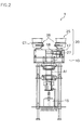
A front sectional diagram of a rotary measuring device pertaining to an embodiment of the present invention. - [
FIG 3 ]
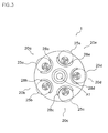
A plan diagram of the rotary measuring device ofFIG. 2 . - [
FIG. 4 ]
A diagram showing an aspect of a measuring plate during rotation in the rotary measuring device ofFIG 2 . - [
FIG 5 ]
A diagram showing the functional configuration of the rotary measuring device ofFIG 2 . - [
FIG 6 ]
A diagram schematically showing the functions of a control unit of the rotary measuring device ofFIG 2 . - [
FIG 7 ]
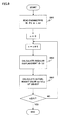
A flowchart showing initial setting processing in the rotary measuring device ofFIG 2 . - [
FIG 8 ]
A flowchart showing measurement processing in a state where an object (object-to-be-measured) has actually been placed on the measuring plate in the rotary measuring device ofFIG 2 . - [
FIG 9 ]
A flowchart showing correction processing in the rotary measuring device ofFIG 2 . -
- 1
- Rotary Measuring Device
- 10
- Circular Box
- 15
- Motor
- 17
- Free End
- 18
- Fixed End
- 20, 20a
- to 20e Measuring Units
- 25, 25a
- to 25e Measuring Plates
- 27, 27a
- to 27e Load Cells
- 28, 28a
- to 28e Holders
- 29
- Memory Unit
- 30
- Control Unit
- 40
- Centrifugal Force Error Calculation Block
- 41
- Angular Displacement Function Calculation Block
- 42
- Initial Load Calculation Block
- 43
- Turning Radius Calculation Block
- 50
- Weight Value Calculation Block
- A 1
- Rotating Shaft
- Below, a
rotary measuring device 1 pertaining to an embodiment of the present invention will be described with reference toFIG 1 to FIG 9 . - As shown in
FIG 2 andFIG 3 , therotary measuring device 1 is disposed with amotor 15 that causes arotating shaft A 1 to rotate, plural (in the present embodiment, five) measuringunits 20a to 20e that are fixed to the rotating shaft A1 and rotate about the rotating shaft A1 together with the rotating shaft A1, and a control unit 30 (seeFIG 5 ) that controls the operation of each part of therotary measuring device 1. Additionally, the measuringunits 20a to 20e includeload cells 27a to 27e (seeFIG. 5 ),holders 28a to 28e disposed so as to correspond to theload cells 27a to 27e, and measuringplates 25a to 25e that theholders 28a to 28e hold, respectively. - The
motor 15 is inverter-controlled and can cause the rotating shaft A1 to rotate an arbitrary number of rotations in response to a command from thecontrol unit 30. Acircular box 10 is fixed to the rotating shaft A1, and thecircular box 10 rotates the same number of rotations as the rotating shaft A1. - The measuring
units 20a to 20e rotate a certain number of rotations about the rotating shaft A1. Additionally, while the measuringunits 20a to 20e rotate once about the rotating shaft A1, objects are supplied to the measuringplates 25a to 25e, the supplied objects are measured, and the measured objects are discharged from the measuringplates 25a to 25e. More specifically, in therotary measuring device 1, as shown inFIG 4 , a supply area L1, a measurement area L2, and a discharge area L3 are set along the rotational trajectory of the measuringplates 25a to 25e. In the supply area L1, objects are supplied to theempty measuring plates 25a to 25e by an unillustrated supply unit. In the measurement area L2, the weights of the objects that have been supplied to the measuringplates 25a to 25e are measured by theload cells 27a to 27e together with the weights of the measuringplates 25a to 25e and theholders 28a to 28e (below, tares). Next, in the discharge area L3, the objects after measurement are discharged by an unillustrated discharge unit from the measuringplates 25a to 25e to the outside of the rotational trajectory of the measuringplates 25a to 25e. Then, the measuringplates 25a to 25e for which the process from supply to discharge of the objects has ended are again sent to the process from supply to discharge of the next objects. - The
holders 28a to 28e include bottom panels that support the measuringplates 25a to 25e from below and U-shaped members, and theholders 28a to 28e hold the measuringplates 25a to 25e between the bottom panels and the U-shaped members by placing the U-shaped members along flange portions C1 formed on the outer peripheries of the measuringplates 25a to 25e. Moreover, magnets (permanent magnets) are embedded in the bottom panels of theholders 28 so that themetal measuring plates 25a to 25e are more securely held by the magnetic force of these magnets. It will be noted that the magnets may also be embedded in side walls rather than the bottom panels, or may also be embedded in both the bottom panels and the side walls. Further, in addition to or instead of being held by the magnets, the measuringplates 25a to 25e may also be mechanically held by disposing appropriate engaging portions in theholders 28a to 28e, or in the measuringplates 25a to 25e, or in both, and the like. Further, the measuringplates 25a to 25e may also be held by strictly designing theholders 28a to 28e and the measuringplates 25a to 25e to abut against each other rather than disposing a special holding mechanism having magnets, engaging portions, or the like. - Further, as shown in
FIG. 2 andFIG. 3 , theholders 28a to 28e are fixed on thecircular box 10 and arranged at equidistant intervals in the circumferential direction of thecircular box 10. Consequently, theholders 28a to 28e rotate the same number of rotations as thecircular box 10 in accordance with the rotation of thecircular box 10 while holding the measuringplates 25a to 25e respectively. - The measuring
plates 25a to 25e are configured such that objects can be placed thereon. When objects are placed on the measuringplates 25a to 25e, the weights of the objects are loaded on the measuringplates 25a to 25e. Additionally, as shown inFIG 1 , the load that the measuringplate 25 receives travels tofree end 17 of theload cell 27 together with the weight of the tare including the measuringplate 25 and causes theload cell 27 to be angularly displaced with respect to a horizontal plate in the vicinity of thefree end 17. - As shown in
FIG 2 , theload cells 27a to 27e are fixed inside thecircular box 10 and arranged at equidistant intervals in the circumferential direction of thecircular box 10. Consequently, theload cells 27a to 27e rotate the same number of rotations as thecircular box 10 in accordance with the rotation of thecircular box 10 together with theholders 28a to 28e and the measuringplates 25a to 25e. That is, measurement by theload cells 27a to 27e is performed in a state where theload cells 27a to 27e, the measuringplates 25a to 25e, and theholders 28a to 28e are relatively stopped. Thus, even when the measuringplates 25a to 25e are caused to rotate, the similar accurate measurement can be performed as when the rotation of the measuringplates 25a to 25e is stopped. - Further, as shown in
FIG. 1 , theload cell 27 includes thefree end 17 and fixedend 18, and theload cell 27 detects and measures the load that thefree end 17 receives and outputs the measured value to thecontrol unit 30. As shown inFIG 2 , the measuringplate 25 is disposed above thefree end 17 of theload cell 27 in the vertical direction, and the weight of an object placed on the measuringplate 25 and the weight of the tare are loaded on thefree end 17. Consequently, not just the weight of the object placed on the measuringplate 25 and the weight of the tare, but also error resulting from rotation such as centrifugal force error stemming from angular displacement θ with respect to the horizontal place of theload cell 27 is included in the measured value outputted from theload cell 27, that is, the load that thefree end 17 receives. - As shown in
FIG. 5 , thecontrol unit 30 is connected to theload cells 27a to 27e, amemory unit 29 and themotor 15. Thus, thecontrol unit 30 can control the operation of each part of therotary measuring device 1 by reading and executing programs stored in thememory unit 29. Additionally, on the basis of the measured values outputted from theload cells 27a to 27e, thecontrol unit 30 calculates the actual weight values of the objects placed on the measuringplates 25a to 25e. The actual weight values of the objects that have been calculated are saved in thememory unit 29 and outputted in a format that an operator has set via an unillustrated setting input unit such as operation keys. For example, the actual weight values are displayed on an unillustrated monitor attached to therotary measuring device 1 or are sent to a downstream device included in the same production line as therotary measuring device 1. - Further, as shown in
FIG 6 , thecontrol unit 30 functions as a centrifugal forceerror calculation block 40 and a weightvalue calculation block 50 by reading and executing acorrection program 29a and aninitial setting program 29b stored in thememory unit 29. The centrifugal forceerror calculation block 40 calculates the angular displacements θ that are needed in order to consider the centrifugal force error included in the measured values outputted from theload cells 27a to 27e in a state where objects (objects-to-be-measured) have been placed on the measuringplates 25a to 25e. The weightvalue calculation block 50 calculates the actual weight values of the objects (objects-to-be-measured) on the basis of the angular displacements θ calculated by the centrifugal forceerror calculation block 40. - Further, the centrifugal force
error calculation block 40 includes an angular displacementfunction calculation block 41, an initialload calculation block 42, a turningradius calculation block 43 and an angulardisplacement calculation block 44. The angular displacementfunction calculation block 41 calculates a function representing the angular displacement θ depending on the load that thefree end 17 receives. The initialload calculation block 42 calculates the initial load that thefree end 17 receives. It will be noted that the initial load that thefree end 17 receives is a load that thefree end 17 receives in an initial state where no objects have been placed on the measuringplates 25a to 25e and where the measuringunits 20a to 20e are not rotating, and is equivalent to the weight of the tare. The turningradius calculation block 43 calculates a turning radius that is the distance between thefree end 17 and a rotational center of the measuringunits 20a to 20e. The angulardisplacement calculation block 44 calculates, on the basis of the calculation results in theblocks 41 to 43, the specific angular displacement θ in a state where objects (objects-to-be-measured) have been placed on the measuringplates 25a to 25e. - Below, initial setting processing in the
rotary measuring device 1 will be described with reference toFIG. 7 . The initial setting processing is processing that calculates parameters that are needed in order to calculate the actual weight values of objects (objects-to-be-measured) before performing measurement processing in a state where the objects (objects-to-be-measured) have actually been placed on the measuringplates 25. - In step S71, the
control unit 30 causes the measuringplate 25 in a state where no objects have been placed thereon, that is, the measuringplate 25 in a state where just the tare weight is loaded on thefree end 17 of theload cell 27, to rotate a number of rotations R1 [rpm] (e.g., 30 rpm). In this state, theload cell 27 outputs a measured value F1 [N]. It will be noted that the angular speed corresponding to this number of rotations R1 is ω1 (ω1 = 2πR1/60) [rad/s]. Next, in step S72, thecontrol unit 30 causes the measuringplate 25 in a state where no objects have been placed thereon, that is, the measuringplate 25 in a state where just the tare weight is loaded on thefree end 17 of theload cell 27, to rotate a number of rotations R2 [rpm] (e.g., 60 rpm). In this state, theload cell 27 outputs a measured value F2 [N]. It will be noted that the angular speed corresponding to this number of rotations R2 is ω2 (ω2 = 2πR2/60) [rad/s]. - Next, in step S73, the
control unit 30 causes the measuringplate 25 in a state where an object having the same weight as the rated maximum weight (e.g., weight of an object with a mass of 5 kg) of theload cell 27 has been placed thereon, that is, the measuringplate 25 in a state where the total weight of the tare weight and the rated maximum weight of theload cell 27 is loaded on thefree end 17 of theload cell 27, to rotate the number of rotations R1. In this state, theload cell 27 outputs a measured value F3 [N]. - Next, in step S74, the
control unit 30 causes the measuringplate 25 in a state where an object having the same weight as the rated maximum weight of theload cell 27 has been placed thereon, that is, the measuringplate 25 in a state where the total weight of the tare weight and the rated maximum weight of theload cell 27 is loaded on thefree end 17 of theload cell 27, to rotate the number of rotations R2. In this state, theload cell 27 outputs a measured value F4 [N]. - Next, in step S75, the
control unit 30 functions as the angular displacementfunction calculation block 41, the initialload calculation block 42, and the turningradius calculation block 43. Theblocks 41 to 43 operate mutually cooperatively, so that theblocks 41 to 43 calculate, respectively, a function representing the angular displacement θ depending on the load that thefree end 17 of theload cell 27 receives, the tare weight value (initial load value), and the turning radius that is the distance between thefree end 17 and the rotational center of the measuringunit 20, on the basis of the measured values F1 to F4 outputted from theload cell 27 in steps S71 to S74. - In step S75, calculation is performed in accordance with the following derivation principle.
- As shown in
FIG. 1 , the total weight of the tare weight and the weight of the object placed on the measuringplate 25 is loaded downward in the vertical direction on theload cell 27, and a force FE resulting from centrifugal force error is also loaded upward in the vertical direction on theload cell 27. Consequently, when F [N] represents the load that thefree end 17 of theload cell 27 receives, M [kg] represents the mass of the tare, m [kg] represents the mass of the object placed on the measuringplate 25, r [m] represents the turning radius, ω [rad/s] represents the angular speed, and g [m/s2] represents gravitational acceleration, then usually the following relationship is established between these physical values:
At this time, this becomes:
- Moreover, the angular displacement θ [rad] with respect to the horizontal plane of the
load cell 27 in the vicinity of thefree end 17 is represented by:
Here, θ0 is the initial angular displacement in a state where thefree end 17 is not receiving a load, and α is a constant. The above expression (3) means that the angular displacement θ is proportional to the load F that thefree end 17 receives. - Here, when the above expression (3) is substituted in the above expression (1), then it becomes:

- When the measurement results in steps S71 to S74 are substituted in the above expression (4), then the following four expressions (5) to (8) are obtained.


- Here, mmax [kg] is the mass of an object having the rated maximum weight.
- In step S75, the
control unit 30 solves the above four expressions (5) to (8) for the four unknowns θ0, α, M, and r. That is, the function θ0 + αF representing the angular displacement θ depending on the force F that thefree end 17 receives, the tare weight value (initial load value) M, and the turning radius r that is the distance between thefree end 17 and the rotational center of the measuringunit 20 are , respectively, calculated by the angular displacementfunction calculation block 41, the initialload calculation block 42, and the turningradius calculation block 43. The four values of θ0, α, M and r calculated at this time are stored in thememory unit 29 and utilized as parameters in later-described correction processing. - It will be noted that each of the measured values F1 to F4 outputted in steps S71 to S74 is the average value among a predetermined number of measured values, which are obtained from the predetermined number of measurements under a measurement condition corresponding to the step S71 to S74. Thus, measurement error can be minimized.
- Further, in the present embodiment, steps S71 to S75 are executed for each of the five
measuring units 20a to 20e, so that five sets, which correspond to respectively the measuringunits 20a to 20e, of the parameters θ0, α, M and r are stored in thememory unit 29. In this manner, because the parameters in later-described correction processing are calculated in accordance with the characteristics of each of the measuringunits 20a to 20e, the actual weight values of the objects (objects-to-be-measured) can be calculated more accurately. - Next, measurement processing in a state where objects (objects-to-be-measured) have actually been placed on the measuring
plates 25 will be described with reference toFIG 8 . Each of the objects (objects-to-be-measured) is an object having a mass of about 1 kg, for example. - In step S81, the
control unit 30 drives themotor 15 to cause the measuringunits 20 to rotate a predetermined number of rotations Rr [rpm] designated by the operator of therotary measuring device 1. At this time, the value Rr representing the number of rotations is stored in thememory unit 29 and utilized as a parameter in later-described correction processing. It will be noted that the angular speed corresponding to this number of rotations Rr is ωr (ωr = 2πRr/60) [rad/s]. - Next, in step S82, the
control unit 30 verifies whether or not the parts of therotary measuring device 1 are synchronized with each other and whether or not therotary measuring device 1 is synchronized with various types of devices included in the production line disposed downstream and upstream of therotary measuring device 1. When synchronization has not been achieved, then thecontrol unit 30 stands by until synchronization is achieved, and when synchronization has been achieved, then thecontrol unit 30 proceeds to step S83. - In step S83, the load that the
free end 17 of theload cell 27 receives is measured by theload cell 27 when the measuringplate 25 to which an object (object-to-be-measured) has been supplied passes through the measurement area L2, and the measured value is stored in thememory unit 29. - The measuring
units 20 continue to rotate until a stop command is inputted from the operator of therotary measuring device 1 or until a predesignated operation end time has been reached. Consequently, step S83 is repeated N times for N number (where N is a positive integer) of objects (objects-to-be-measured) until a stop command is inputted from the operator of therotary measuring device 1 or until the predesignated operation end time has been reached. Here, the mass of the object (object-to-be-measured) that has been measured the nth time (n = 1, 2, ···, N) is mr (n) [kg]. Further, thecontrol unit 30 stores the N number of measured values outputted from theload cells 27 associated with the measured order in thememory unit 29 as Fr (n) (n = 1, 2, ···, N) [N]. The measured values Fr (n) (n = 1, 2, ···, N) stored in thememory unit 29 are utilized in later-described correction processing. - Below, correction processing in the
rotary measuring device 1 will be described with reference toFIG. 9 . The correction processing is processing that corrects, on the basis of the parameters θ0, α, M and r calculated by the initial setting processing, the measured values Fr (n) (n = 1, 2, ···, N) in a state where objects (objects-to-be-measured) have actually been placed on the measuringplates 25, to calculate the actual weight values of the objects (objects-to-be-measured). The correction processing is executed in parallel with the aforementioned measurement processing by thecontrol unit 30. - In step S91, the
control unit 30 functions as the centrifugal forceerror calculation block 40. The centrifugal forceerror calculation block 40 reads the parameters θ0, α, M, r and ωr and the measured values Fr (n) (n = 1, 2, ···, N) stored in thememory unit 29. - Next, in step S92, the angular
displacement calculation block 44 calculates, on the basis of expression (9) below, the angular displacement θr (n) (n = 1, 2, ···, N) [rad] in a state where an object (object-to-be-measured) with mass mr (n) (n = 1, 2, ···, N) has been placed on the measuringplate 25.
- It will be noted that the above expression (9) is obtained by the above expression (3).
- Next, in step S93, the
control unit 30 functions as the weightvalue calculation block 50. The weightvalue calculation block 50 calculates, on the basis of the angular displacement θr (n) (n = 1, 2, ···, N) calculated in step S92, the actual mass value mr (n) (n = 1, 2, ···, N) of the object (object-to-be-measured) from the following expression (10).
- It will be noted that the above expression (10) is one where known values are substituted in an expression obtained by transforming the above expression (1).
- Then, the weight
value calculation block 50 calculates the actual weight value of the object (object-to-be-measured) by multiplying the gravitational acceleration g by the actual mass value mr (n) (n = 1, 2, ···, N) of the object (object-to-be-measured) calculated by expression (10). - Then, the
control unit 30 repeats steps S92 and S93 N times for n = 1, ···, N. - It will be noted that the set of parameters θ0, α, M and r utilized in steps S92 and S93 is selected from the five sets of parameters θ0, α, M and r stored in the
memory unit 29, corresponding to that one unit of the measuringunits 20a to 20e to which the object (object-to-be-measured) to be calculated has been supplied. - In this
rotary measuring device 1, the angular displacement θ with respect to the horizontal plane of theload cell 27 in the vicinity of thefree end 17 in a state where an object (object-to-be-measured) has been placed on the measuringplate 25 is calculated on the basis of measured values (first measured values) in a state where the measuringunit 20 is rotating. Additionally, the actual weight value mr (n) g (n = 1, 2, ···, N) of the object (object-to-be-measured) is calculated on the basis of the calculated angular displacement θ and a measured value (second measured value) in a state where the object (object-to-be-measured) has been placed on the measuringplate 25. In this manner, in thisrotary measuring device 1, by considering the angular displacement θ in a state where an object (object-to-be-measured) has been placed on the measuringplate 25, it becomes possible to more accurately consider centrifugal force error, and the weight of the object (object-to-be-measured) can be measured more accurately. - In this
rotary measuring device 1, the angular displacement θ is calculated on the basis of measured values (first measured values) in a state where the measuringunit 20 is actually rotating. Thus, in thisrotary measuring device 1, the angular displacement θ in a state where the measuringunit 20 is rotating can be calculated more accurately. - In this
rotary measuring device 1, the function θ = θ0 + αF representing the angular displacement θ depending on the load F that thefree end 17 receives, the tare weight value (initial load value) M, and the turning radius r that is the distance between thefree end 17 and the rotational center of the measuringunit 20 are calculated on the basis of measured values (first measured values) in a state where the measuringunit 20 is rotating. In this manner, in thisrotary measuring device 1, it becomes possible to consider the angular displacement θ, the tare weight value (initial load value) M, and the turning radius r, and the weight of the object (object-to-be-measured) can be measured more accurately. - In this
rotary measuring device 1, the parameters θ0, α, M and r that are needed in order to calculate the actual weight value of an object (object-to-be-measured) are calculated in regard to four types of measured values (first measured values) in a total of four types of states which are two types of states where no objects have been placed on the measuringplate 25 and two types of states where an object having the rated maximum weight of theload cell 27 has been placed on the measuringplate 25. Thus, in thisrotary measuring device 1, in regard to various objects (objects-to-be-measured) having various weights from zero to the rated maximum weight, the angular displacement θ in a state where the object (object-to-be-measured) has been placed on the measuringplate 25 can be measured more accurately. - In this
rotary measuring device 1, the initial setting processing shown inFIG 7 is executed for each of the fivemeasuring units 20a to 20e, so that five sets, which correspond to respectively the measuringunits 20a to 20e, of the parameters θ0, α, M and r are stored in thememory unit 29. Additionally, when the actual weight value of the object (object-to-be-measured) is to be calculated, of the five sets of parameters θ0, α, M and r stored in thememory unit 29, the set of parameters corresponding to that one unit of the measuringunits 20a to 20e to which the object (object-to-be-measured) serving as calculation targets has been supplied is utilized. In this manner, because the parameters in the correction processing are calculated in accordance with the characteristics of each of the measuringunits 20a to 20e, the actual weight values of the objects (objects-to-be-measured) can be calculated more accurately. - The measured values F1 to F4 in the initial setting processing shown in
FIG 7 are, after a predetermined number of measurements have been performed under respective measurement conditions, calculated by averaging these measured values. Thus, measurement error can be minimized. - An embodiment of the present invention has been described above, but the present invention is not limited to the preceding embodiment and may be variously altered in a range that does not depart from the gist of the invention.
- In the preceding embodiment, the four parameters θ0, α, M and r were calculated on the basis of the measured values F1 to F4 in states where no objects were placed on the measuring
plate 25 and in states where an object having the rated maximum weight was placed on the measuringplate 25, but it is also possible to calculate the parameters on the basis of four types of measured values in arbitrary four types of states. - The tare weight value (initial weight value) M and/or the turning radius r may be known values on the basis of design specifications. In this case, the number of parameters to be calculated decreases and calculation becomes easy.
- In the preceding embodiment, the objects were placed on the measuring
plates 25 which were held by theholders 28, but the measuringplates 25 may also be placed on theload cells 27 without being held by theholders 28, or the objects may be placed on a belt conveyor. - However, in a rotary measuring device that performs measurement processing while causing measuring plates to rotate as in the preceding embodiment, the centrifugal force acting on the measuring plates becomes greater as the number of rotations of the measuring plates becomes greater, and there is the potential for the measuring plates to fly out from the measuring units, so it is preferable to perform measurement processing in a state where the measuring plates are held using holding members such as holders.
- The present invention has the effect that it is possible to measure more accurately the weight of an object by more accurately considering centrifugal force error and is useful as a rotary measuring device that measures the weight of an object.
Claims (5)
- A rotary measuring device that measures the weight of an object, the rotary measuring device comprising:a measuring unit including a load receiver that receives a load resulting from the object and a load detector having a fixed end and a free end on which the load receiver is disposed;a rotational drive unit that causes the measuring unit to rotate;a centrifugal force error calculating unit that calculates, on the basis of a first measured value outputted from the load detector in a state where the measuring unit is rotating, an angular displacement θ with respect to a horizontal plane of the load detector in the vicinity of the free end; anda weight value calculating unit that calculates a weight value of the object on the basis of the angular displacement θ and a second measured value outputted from the load detector in a state where the load receiver is receiving the load resulting from the object.
- The rotary measuring device of claim 1, wherein the centrifugal force error calculating unit includes angular displacement function calculating means that calculates, on the basis of the first measured value, a function representing the angular displacement θ depending on the load that the free end receives.
- The rotary measuring device of claim 2, wherein the centrifugal force error calculating unit further includes initial load calculating means that calculates a weight value of the load receiver on the basis of the first measured value.
- The rotary measuring device of claim 3, wherein the centrifugal force error calculating unit further includes turning radius calculating means that calculates, on the basis of the first measured value, a turning radius that is the distance between the free end and a rotational center of the measuring unit.
- The rotary measuring device of claim 4, wherein the first measured value includes
a measured value outputted from the load detector in a state where the load receiver is not receiving a load resulting from an object and where the measuring unit is rotating at a first rotational speed,
a measured value outputted from the load detector in a state where the load receiver is not receiving a load resulting from an object and where the measuring unit is rotating at a second rotational speed,
a measured value outputted from the load detector in a state where the load receiver is receiving a load resulting from an object having a rated maximum weight and where the measuring unit is rotating at the first rotational speed, and
a measured value outputted from the load detector in a state where the load receiver is receiving a load resulting from an object having the rated maximum weight and where the measuring unit is rotating at the second rotational speed.
Applications Claiming Priority (3)
| Application Number | Priority Date | Filing Date | Title |
|---|---|---|---|
| JP2005368008 | 2005-12-21 | ||
| JP2006033352 | 2006-02-10 | ||
| PCT/JP2006/325370 WO2007072853A1 (en) | 2005-12-21 | 2006-12-20 | Rotary measuring device |
Publications (2)
| Publication Number | Publication Date |
|---|---|
| EP1970681A1 true EP1970681A1 (en) | 2008-09-17 |
| EP1970681A4 EP1970681A4 (en) | 2011-01-19 |
Family
ID=38188629
Family Applications (1)
| Application Number | Title | Priority Date | Filing Date |
|---|---|---|---|
| EP06842924A Withdrawn EP1970681A4 (en) | 2005-12-21 | 2006-12-20 | Rotary measuring device |
Country Status (4)
| Country | Link |
|---|---|
| US (1) | US7816612B2 (en) |
| EP (1) | EP1970681A4 (en) |
| JP (1) | JPWO2007072853A1 (en) |
| WO (1) | WO2007072853A1 (en) |
Families Citing this family (2)
| Publication number | Priority date | Publication date | Assignee | Title |
|---|---|---|---|---|
| EP1970681A4 (en) * | 2005-12-21 | 2011-01-19 | Ishida Seisakusho | Rotary measuring device |
| DE102015119062B4 (en) * | 2015-11-06 | 2017-11-02 | Sartorius Lab Instruments Gmbh & Co. Kg | Carousel scale and method for its operation |
Family Cites Families (9)
| Publication number | Priority date | Publication date | Assignee | Title |
|---|---|---|---|---|
| JPH0798521B2 (en) | 1986-08-20 | 1995-10-25 | 澁谷工業株式会社 | Rotary weight filling device |
| JP2794472B2 (en) * | 1989-12-21 | 1998-09-03 | 大和製衡株式会社 | Rotary weighing method |
| US5646375A (en) * | 1995-01-23 | 1997-07-08 | Tedea-Huntleigh International Ltd. | Symmetrical load cells for use in conjuction with rotary machines |
| US5700982A (en) * | 1995-01-23 | 1997-12-23 | Tedea-Huntleigh International, Ltd. | Symmetrical load cells for use in conjunction with rotary machines |
| US5798487A (en) * | 1996-01-18 | 1998-08-25 | Tedea Huntleigh Intl. Ltd. | Weighing device for rotary filling machines |
| JP4142978B2 (en) * | 2003-05-08 | 2008-09-03 | 大和製衡株式会社 | Weighing method and rotary weight filling device |
| JP4443258B2 (en) * | 2004-02-25 | 2010-03-31 | 大和製衡株式会社 | Weighing method and rotary weight filling device |
| EP1970681A4 (en) * | 2005-12-21 | 2011-01-19 | Ishida Seisakusho | Rotary measuring device |
| EP3380604B1 (en) * | 2015-11-24 | 2022-12-28 | GlaxoSmithKline Intellectual Property Development Limited | Stable cell lines for retroviral production |
-
2006
- 2006-12-20 EP EP06842924A patent/EP1970681A4/en not_active Withdrawn
- 2006-12-20 US US12/158,362 patent/US7816612B2/en not_active Expired - Fee Related
- 2006-12-20 WO PCT/JP2006/325370 patent/WO2007072853A1/en not_active Ceased
- 2006-12-20 JP JP2007551115A patent/JPWO2007072853A1/en active Pending
Also Published As
| Publication number | Publication date |
|---|---|
| WO2007072853A1 (en) | 2007-06-28 |
| US7816612B2 (en) | 2010-10-19 |
| EP1970681A4 (en) | 2011-01-19 |
| JPWO2007072853A1 (en) | 2009-05-28 |
| US20090229891A1 (en) | 2009-09-17 |
Similar Documents
| Publication | Publication Date | Title |
|---|---|---|
| US8251883B2 (en) | Automatic balance adjusting centrifuge and the control method thereof | |
| JP6431550B2 (en) | How to determine the amount of unbalance in the rotor | |
| DK2665930T3 (en) | Method for determining the slope of a tower | |
| EP0133229B1 (en) | Wheel balancer two plane calibration method | |
| US11060941B2 (en) | Method for determining an unbalance of a shaft-elastic rotor with reference to the outward deflection | |
| JP5541689B2 (en) | Monitoring method and dynamic balance measuring device in balance test | |
| CN114127528A (en) | Method and drive train test stand for detecting imbalances and/or misalignments | |
| CN100595530C (en) | Weighing devices, especially multi-track weighing devices | |
| CN103900763B (en) | Tire multistage wheel rim amount of unbalance scaling method | |
| US9057650B2 (en) | Method for correcting permanent calibration and force-measuring balancing machine | |
| US7816612B2 (en) | Rotary measuring device | |
| CN101368866B (en) | Method for balancing a vehicle wheel | |
| US20150096371A1 (en) | Speed sensor identification | |
| JP7382143B2 (en) | How to calibrate a balancing machine | |
| JP4443258B2 (en) | Weighing method and rotary weight filling device | |
| EP0866318A1 (en) | Automatic calibration check arrangement in a measuring device | |
| JP2011012993A (en) | Metering instrument | |
| JP2000221096A (en) | Balance tester and balance test method | |
| JP4578216B2 (en) | Control method of weight filling apparatus and weight filling apparatus | |
| JP4142978B2 (en) | Weighing method and rotary weight filling device | |
| JP5257762B2 (en) | Apparatus and method for measuring rotational balance of high-speed rotating body | |
| JP5103205B2 (en) | Weighing device | |
| CN106645798A (en) | Method for detecting accelerometer scale factor stability | |
| CN119063952B (en) | Testing methods, apparatus, electronic equipment and storage media of testing machines | |
| JP2011133485A (en) | Rotating type weighing apparatus |
Legal Events
| Date | Code | Title | Description |
|---|---|---|---|
| PUAI | Public reference made under article 153(3) epc to a published international application that has entered the european phase |
Free format text: ORIGINAL CODE: 0009012 |
|
| 17P | Request for examination filed |
Effective date: 20080716 |
|
| AK | Designated contracting states |
Kind code of ref document: A1 Designated state(s): DE GB |
|
| RBV | Designated contracting states (corrected) |
Designated state(s): DE GB |
|
| A4 | Supplementary search report drawn up and despatched |
Effective date: 20101221 |
|
| STAA | Information on the status of an ep patent application or granted ep patent |
Free format text: STATUS: THE APPLICATION IS DEEMED TO BE WITHDRAWN |
|
| 18D | Application deemed to be withdrawn |
Effective date: 20110719 |