EP1970652A1 - Air conditioner - Google Patents
Air conditioner Download PDFInfo
- Publication number
- EP1970652A1 EP1970652A1 EP06834463A EP06834463A EP1970652A1 EP 1970652 A1 EP1970652 A1 EP 1970652A1 EP 06834463 A EP06834463 A EP 06834463A EP 06834463 A EP06834463 A EP 06834463A EP 1970652 A1 EP1970652 A1 EP 1970652A1
- Authority
- EP
- European Patent Office
- Prior art keywords
- refrigerant
- circuit
- refrigerant circuit
- heat exchanger
- pipe
- Prior art date
- Legal status (The legal status is an assumption and is not a legal conclusion. Google has not performed a legal analysis and makes no representation as to the accuracy of the status listed.)
- Granted
Links
Images


Classifications
-
- F—MECHANICAL ENGINEERING; LIGHTING; HEATING; WEAPONS; BLASTING
- F25—REFRIGERATION OR COOLING; COMBINED HEATING AND REFRIGERATION SYSTEMS; HEAT PUMP SYSTEMS; MANUFACTURE OR STORAGE OF ICE; LIQUEFACTION SOLIDIFICATION OF GASES
- F25B—REFRIGERATION MACHINES, PLANTS OR SYSTEMS; COMBINED HEATING AND REFRIGERATION SYSTEMS; HEAT PUMP SYSTEMS
- F25B49/00—Arrangement or mounting of control or safety devices
-
- F—MECHANICAL ENGINEERING; LIGHTING; HEATING; WEAPONS; BLASTING
- F25—REFRIGERATION OR COOLING; COMBINED HEATING AND REFRIGERATION SYSTEMS; HEAT PUMP SYSTEMS; MANUFACTURE OR STORAGE OF ICE; LIQUEFACTION SOLIDIFICATION OF GASES
- F25B—REFRIGERATION MACHINES, PLANTS OR SYSTEMS; COMBINED HEATING AND REFRIGERATION SYSTEMS; HEAT PUMP SYSTEMS
- F25B13/00—Compression machines, plants or systems, with reversible cycle
-
- F—MECHANICAL ENGINEERING; LIGHTING; HEATING; WEAPONS; BLASTING
- F25—REFRIGERATION OR COOLING; COMBINED HEATING AND REFRIGERATION SYSTEMS; HEAT PUMP SYSTEMS; MANUFACTURE OR STORAGE OF ICE; LIQUEFACTION SOLIDIFICATION OF GASES
- F25B—REFRIGERATION MACHINES, PLANTS OR SYSTEMS; COMBINED HEATING AND REFRIGERATION SYSTEMS; HEAT PUMP SYSTEMS
- F25B49/00—Arrangement or mounting of control or safety devices
- F25B49/005—Arrangement or mounting of control or safety devices of safety devices
-
- F—MECHANICAL ENGINEERING; LIGHTING; HEATING; WEAPONS; BLASTING
- F25—REFRIGERATION OR COOLING; COMBINED HEATING AND REFRIGERATION SYSTEMS; HEAT PUMP SYSTEMS; MANUFACTURE OR STORAGE OF ICE; LIQUEFACTION SOLIDIFICATION OF GASES
- F25B—REFRIGERATION MACHINES, PLANTS OR SYSTEMS; COMBINED HEATING AND REFRIGERATION SYSTEMS; HEAT PUMP SYSTEMS
- F25B49/00—Arrangement or mounting of control or safety devices
- F25B49/02—Arrangement or mounting of control or safety devices for compression type machines, plants or systems
-
- F—MECHANICAL ENGINEERING; LIGHTING; HEATING; WEAPONS; BLASTING
- F25—REFRIGERATION OR COOLING; COMBINED HEATING AND REFRIGERATION SYSTEMS; HEAT PUMP SYSTEMS; MANUFACTURE OR STORAGE OF ICE; LIQUEFACTION SOLIDIFICATION OF GASES
- F25B—REFRIGERATION MACHINES, PLANTS OR SYSTEMS; COMBINED HEATING AND REFRIGERATION SYSTEMS; HEAT PUMP SYSTEMS
- F25B2313/00—Compression machines, plants or systems with reversible cycle not otherwise provided for
- F25B2313/023—Compression machines, plants or systems with reversible cycle not otherwise provided for using multiple indoor units
-
- F—MECHANICAL ENGINEERING; LIGHTING; HEATING; WEAPONS; BLASTING
- F25—REFRIGERATION OR COOLING; COMBINED HEATING AND REFRIGERATION SYSTEMS; HEAT PUMP SYSTEMS; MANUFACTURE OR STORAGE OF ICE; LIQUEFACTION SOLIDIFICATION OF GASES
- F25B—REFRIGERATION MACHINES, PLANTS OR SYSTEMS; COMBINED HEATING AND REFRIGERATION SYSTEMS; HEAT PUMP SYSTEMS
- F25B2313/00—Compression machines, plants or systems with reversible cycle not otherwise provided for
- F25B2313/027—Compression machines, plants or systems with reversible cycle not otherwise provided for characterised by the reversing means
- F25B2313/02741—Compression machines, plants or systems with reversible cycle not otherwise provided for characterised by the reversing means using one four-way valve
-
- F—MECHANICAL ENGINEERING; LIGHTING; HEATING; WEAPONS; BLASTING
- F25—REFRIGERATION OR COOLING; COMBINED HEATING AND REFRIGERATION SYSTEMS; HEAT PUMP SYSTEMS; MANUFACTURE OR STORAGE OF ICE; LIQUEFACTION SOLIDIFICATION OF GASES
- F25B—REFRIGERATION MACHINES, PLANTS OR SYSTEMS; COMBINED HEATING AND REFRIGERATION SYSTEMS; HEAT PUMP SYSTEMS
- F25B2400/00—Component parts or details not otherwise provided for in this subclass
- F25B2400/13—Economisers
-
- F—MECHANICAL ENGINEERING; LIGHTING; HEATING; WEAPONS; BLASTING
- F25—REFRIGERATION OR COOLING; COMBINED HEATING AND REFRIGERATION SYSTEMS; HEAT PUMP SYSTEMS; MANUFACTURE OR STORAGE OF ICE; LIQUEFACTION SOLIDIFICATION OF GASES
- F25B—REFRIGERATION MACHINES, PLANTS OR SYSTEMS; COMBINED HEATING AND REFRIGERATION SYSTEMS; HEAT PUMP SYSTEMS
- F25B2500/00—Problems to be solved
- F25B2500/19—Calculation of parameters
-
- F—MECHANICAL ENGINEERING; LIGHTING; HEATING; WEAPONS; BLASTING
- F25—REFRIGERATION OR COOLING; COMBINED HEATING AND REFRIGERATION SYSTEMS; HEAT PUMP SYSTEMS; MANUFACTURE OR STORAGE OF ICE; LIQUEFACTION SOLIDIFICATION OF GASES
- F25B—REFRIGERATION MACHINES, PLANTS OR SYSTEMS; COMBINED HEATING AND REFRIGERATION SYSTEMS; HEAT PUMP SYSTEMS
- F25B2600/00—Control issues
- F25B2600/13—Pump speed control
-
- F—MECHANICAL ENGINEERING; LIGHTING; HEATING; WEAPONS; BLASTING
- F25—REFRIGERATION OR COOLING; COMBINED HEATING AND REFRIGERATION SYSTEMS; HEAT PUMP SYSTEMS; MANUFACTURE OR STORAGE OF ICE; LIQUEFACTION SOLIDIFICATION OF GASES
- F25B—REFRIGERATION MACHINES, PLANTS OR SYSTEMS; COMBINED HEATING AND REFRIGERATION SYSTEMS; HEAT PUMP SYSTEMS
- F25B2600/00—Control issues
- F25B2600/21—Refrigerant outlet evaporator temperature
-
- F—MECHANICAL ENGINEERING; LIGHTING; HEATING; WEAPONS; BLASTING
- F25—REFRIGERATION OR COOLING; COMBINED HEATING AND REFRIGERATION SYSTEMS; HEAT PUMP SYSTEMS; MANUFACTURE OR STORAGE OF ICE; LIQUEFACTION SOLIDIFICATION OF GASES
- F25B—REFRIGERATION MACHINES, PLANTS OR SYSTEMS; COMBINED HEATING AND REFRIGERATION SYSTEMS; HEAT PUMP SYSTEMS
- F25B2700/00—Sensing or detecting of parameters; Sensors therefor
- F25B2700/04—Refrigerant level
-
- F—MECHANICAL ENGINEERING; LIGHTING; HEATING; WEAPONS; BLASTING
- F25—REFRIGERATION OR COOLING; COMBINED HEATING AND REFRIGERATION SYSTEMS; HEAT PUMP SYSTEMS; MANUFACTURE OR STORAGE OF ICE; LIQUEFACTION SOLIDIFICATION OF GASES
- F25B—REFRIGERATION MACHINES, PLANTS OR SYSTEMS; COMBINED HEATING AND REFRIGERATION SYSTEMS; HEAT PUMP SYSTEMS
- F25B45/00—Arrangements for charging or discharging refrigerant
-
- Y—GENERAL TAGGING OF NEW TECHNOLOGICAL DEVELOPMENTS; GENERAL TAGGING OF CROSS-SECTIONAL TECHNOLOGIES SPANNING OVER SEVERAL SECTIONS OF THE IPC; TECHNICAL SUBJECTS COVERED BY FORMER USPC CROSS-REFERENCE ART COLLECTIONS [XRACs] AND DIGESTS
- Y02—TECHNOLOGIES OR APPLICATIONS FOR MITIGATION OR ADAPTATION AGAINST CLIMATE CHANGE
- Y02B—CLIMATE CHANGE MITIGATION TECHNOLOGIES RELATED TO BUILDINGS, e.g. HOUSING, HOUSE APPLIANCES OR RELATED END-USER APPLICATIONS
- Y02B30/00—Energy efficient heating, ventilation or air conditioning [HVAC]
- Y02B30/70—Efficient control or regulation technologies, e.g. for control of refrigerant flow, motor or heating
Definitions
- the present invention relates to a function to judge the adequacy of the refrigerant quantity in a refrigerant circuit of an air conditioner. More specifically, the present invention relates to a function to judge the adequacy of the refrigerant quantity in a refrigerant circuit of an air conditioner configured by the interconnection of a compressor, a heat source side heat exchanger, an expansion mechanism, and a utilization side heat exchanger.
- An object of the present invention is to judge the adequacy of the refrigerant quantity in the refrigerant circuit with high accuracy while reducing the calculation load.
- An air conditioner includes a refrigerant circuit, refrigerant quantity calculating means, and refrigerant quantity judging means.
- the refrigerant circuit is configured by the interconnection of a compressor, a heat source side heat exchanger, and a utilization side heat exchanger.
- the refrigerant quantity calculating means uses a relational expression between the refrigerant quantity in each portion of the refrigerant circuit when refrigerant circuit is divided into a plurality of portions and an operation state quantity of constituent equipment or refrigerant flowing in the refrigerant circuit in order to calculate the refrigerant quantity in each portion from the operation state quantity of constituent equipment or refrigerant flowing in the refrigerant circuit.
- the refrigerant quantity judging means uses the refrigerant quantity in each portion calculated by the refrigerant quantity calculating means in order to judge the adequacy of the refrigerant quantity in the refrigerant circuit.
- the refrigerant circuit is divided into a plurality of portions, and the relational expression between the refrigerant quantity in each portion and the operation state quantity is set. Consequently, compared to the conventional case where a simulation of refrigeration cycle characteristics is performed, the calculation load can be reduced, and an operation state quantity that is important for calculation of the refrigerant quantity in each portion can be selectively incorporated as a variable of the relational expression, thus improving the calculation accuracy of the refrigerant quantity in each portion. As a result, the adequacy of the refrigerant quantity in the refrigerant circuit can be judged with high accuracy.
- the "operation state quantity of constituent equipment or refrigerant flowing in the refrigerant circuit” refers to state quantities such as the temperature, pressure, and the like of the refrigerant flowing in the refrigerant circuit and state quantities of equipment constituting the air conditioner.
- An air conditioner according to a second aspect of the present invention is the air conditioner according to the first aspect of the present invention, wherein the refrigerant circuit is configured by a heat source unit including the compressor and the heat source side heat exchanger; a utilization unit including the utilization side heat exchanger; and a refrigerant communication pipe that interconnects the heat source unit and the utilization unit.
- the relational expressions are separately set for the refrigerant communication pipe and a portion other than the refrigerant communication pipe as the refrigerant circuit is divided into these portions.
- the refrigerant circuit is divided into the refrigerant communication pipe where the refrigerant quantity changes depending on conditions such as an installation location and the like and the portion other than the refrigerant communication pipe, and the relational expressions between the refrigerant quantity in each portion and the operation state quantity are set.
- the relational expression for calculating the refrigerant quantity in the portion other than the refrigerant communication pipe it is possible to use the relational expressions in which a calculation error due to the change in the refrigerant quantity in the refrigerant communication pipe is not easily generated.
- the accuracy for judging the adequacy of the refrigerant quantity in the refrigerant circuit can be further improved.
- An air conditioner according to a third aspect of the present invention is the air conditioner according to the second aspect of the present invention, wherein the relational expressions are separately set for the heat source unit and the utilization unit as the portion other than the refrigerant communication pipe is divided into these portions.
- the portion other than the refrigerant communication pipe is divided into the heat source unit and the utilization unit, and the relational expressions between the refrigerant quantity in each portion and the operation state quantity are set.
- the relational expressions separately provided for the heat source unit and the utilization unit can be used.
- the accuracy for judging the adequacy of the refrigerant quantity in the refrigerant circuit can be further improved.
- An air conditioner according to a fourth aspect of the present invention is the air conditioner according to the third aspect of the present invention, wherein the relational expressions are separately set for the heat source side heat exchanger and a portion other than the heat source side heat exchanger as the heat source unit is divided into these portions.
- the relational expression set for the refrigerant quantity in the heat source side heat exchanger includes a refrigerant circulation flow rate or an operation state quantity equivalent to the refrigerant circulation flow rate as the operation state quantity of constituent equipment or refrigerant flowing in the refrigerant circuit.
- the heat source unit is divided into the heat source side heat exchanger and the portion other than the heat source side heat exchanger, and the relational expressions between the refrigerant quantity in each portion and the operation state quantity are set.
- the operation state quantity used in the relational expression for calculating the refrigerant quantity in the heat source side heat exchanger a refrigerant circulation flow rate or an operation state quantity equivalent to the refrigerant circulation flow rate is included.
- An air conditioner according to a fifth aspect of the present invention is the air conditioner according to the third or fourth aspect of the present invention, wherein the utilization unit further includes a ventilation fan that supplies air to the utilization side heat exchanger.
- the relational expression set for the refrigerant quantity in the utilization unit includes an air flow rate of the ventilation fan or an operation state quantity equivalent to the air flow rate as the operation state quantity of constituent equipment or refrigerant flowing in the refrigerant circuit.
- an air flow rate of the ventilation fan or an operation state quantity equivalent to the air flow rate is included.
- the accuracy for judging the adequacy of the refrigerant quantity in the refrigerant circuit can be further improved.
- An air conditioner according to a sixth aspect of the present invention is the air conditioner according to any one of the first through fifth aspects of the present invention, wherein the refrigerant quantity calculating means uses the relational expressions in order to calculate the refrigerant quantity in each portion from the operation state quantity of constituent equipment or refrigerant flowing in the refrigerant circuit in an automatic refrigerant charging operation in which the refrigerant is charged into the refrigerant circuit.
- the refrigerant quantity judging means uses the refrigerant quantity in each portion calculated by the refrigerant quantity calculating means in order to judge whether or not the refrigerant quantity in the refrigerant circuit has reached a target charge value.
- the refrigerant quantity can be quickly calculated, and moreover, whether or not the refrigerant quantity in the refrigerant circuit has reached the target charge value can be judged with high accuracy.
- An air conditioner according to a seventh aspect of the present invention is the air conditioner according to any one of the first through sixth aspects of the present invention, wherein the refrigerant quantity calculating means uses the relational expressions in order to calculate the refrigerant quantity in each portion from the operation state quantity of constituent equipment or refrigerant flowing in the refrigerant circuit in an initial refrigerant quantity detection operation in which the initial refrigerant quantity after constituent equipment is installed or after the refrigerant is charged into the refrigerant circuit is detected, and thereby detects the initial refrigerant quantity.
- the refrigerant quantity can be quickly calculated, and moreover, the initial refrigerant quantity can be detected with high accuracy.
- An air conditioner according to an eighth aspect of the present invention is the air conditioner according to any one of the first through seventh aspects of the present invention, wherein the refrigerant quantity calculating means uses the relational expressions in order to calculate the refrigerant quantity in each portion from the operation state quantity of constituent equipment or refrigerant flowing in the refrigerant circuit in a refrigerant leak detection operation in which whether or not the refrigerant is leaking from the refrigerant circuit is judged.
- the refrigerant quantity judging means compares the refrigerant quantity in each portion calculated by the refrigerant quantity calculating means with a reference refrigerant quantity that serves as the reference for judging whether or not there is a leak, and thereby judges whether or not the refrigerant is leaking from the refrigerant circuit.
- the refrigerant quantity can be quickly calculated, and moreover, whether or not the refrigerant is leaking from the refrigerant circuit can be judged with high accuracy.
- FIG. 1 is a schematic configuration view of an air conditioner 1 according to an embodiment of the present invention.
- the air conditioner 1 is a device that is used to cool and heat a room in a building and the like by performing a vapor compression-type refrigeration cycle operation.
- the air conditioner 1 mainly includes one outdoor unit 2 as a heat source unit, indoor units 4 and 5 as a plurality (two in the present embodiment) of utilization units connected in parallel thereto, and a liquid refrigerant communication pipe 6 and a gas refrigerant communication pipe 7 as refrigerant communication pipes which interconnect the outdoor unit 2 and the indoor units 4 and 5.
- the vapor compression-type refrigerant circuit 10 of the air conditioner 1 in the present embodiment is configured by the interconnection of the outdoor unit 2, the indoor units 4 and 5, and the liquid refrigerant communication pipe 6 and the gas refrigerant communication pipe 7.
- the indoor units 4 and 5 are installed by being embedded in or hung from a ceiling of a room in a building and the like or by being mounted or the like on a wall surface of a room.
- the indoor units 4 and 5 are connected to the outdoor unit 2 via the liquid refrigerant communication pipe 6 and the gas refrigerant communication pipe 7, and configure a part of the refrigerant circuit 10.
- the indoor unit 4 mainly includes an indoor side refrigerant circuit 10a (an indoor side refrigerant circuit 10b in the case of the indoor unit 5) that configures a part of the refrigerant circuit 10.
- the indoor side refrigerant circuit 10a mainly includes an indoor expansion valve 41 as an expansion mechanism and an indoor heat exchanger 42 as a utilization side heat exchanger.
- the indoor expansion valve 41 is an electrically powered expansion valve connected to a liquid side of the indoor heat exchanger 42 in order to adjust the flow rate or the like of the refrigerant flowing in the indoor side refrigerant circuit 10a.
- the indoor heat exchanger 42 is a cross fin-type fin-and-tube type heat exchanger configured by a heat transfer tube and numerous fins, and is a heat exchanger that functions as an evaporator for the refrigerant during a cooling operation to cool the room air and functions as a condenser for the refrigerant during a heating operation to heat the room air.
- the indoor unit 4 includes an indoor fan 43 as a ventilation fan for taking in room air into the unit, causing the air to heat exchange with the refrigerant in the indoor heat exchanger 42, and then supplying the air to the room as supply air.
- the indoor fan 43 is a fan capable of varying an air flow rate Wr of the air which is supplied to the indoor heat exchanger 42, and in the present embodiment, is a centrifugal fan, multi-blade fan, or the like, which is driven by a motor 43a comprising a DC fan motor.
- a liquid side temperature sensor 44 that detects the temperature of the refrigerant i.e., the refrigerant temperature corresponding to a condensation temperature Tc during the heating operation or an evaporation temperature Te during the cooling operation
- a gas side temperature sensor 45 that detects a temperature Teo of the refrigerant is disposed at a gas side of the indoor heat exchanger 42.
- a room temperature sensor 46 that detects the temperature of the room air that flows into the unit i.e., a room temperature Tr
- a room temperature Tr is disposed at a room air intake side of the indoor unit 4.
- the liquid side temperature sensor 44, the gas side temperature sensor 45, and the room temperature sensor 46 comprise thermistors.
- the indoor unit 4 includes an indoor side controller 47 that controls the operation of each portion constituting the indoor unit 4.
- the indoor side controller 47 includes a microcomputer and a memory and the like disposed in order to control the indoor unit 4, and is configured such that it can exchange control signals and the like with a remote controller (not shown) for individually operating the indoor unit 4 and can exchange control signals and the like with the outdoor unit 2 via a transmission line 8a.
- the outdoor unit 2 is installed outside of a building and the like, is connected to the indoor units 4 and 5 via the liquid refrigerant communication pipe 6 and the gas refrigerant communication pipe 7, and configures the refrigerant circuit 10 with the indoor units 4 and 5.
- the outdoor unit 2 mainly includes an outdoor side refrigerant circuit 10c that configures a part of the refrigerant circuit 10.
- This outdoor side refrigerant circuit 10c mainly includes a compressor 21, a four-way switching valve 22, an outdoor heat exchanger 23 as a heat source side heat exchanger, an outdoor expansion valve 38 as an expansion mechanism, an accumulator 24, a subcooler 25 as a temperature adjustment mechanism, a liquid side stop valve 26, and a gas side stop valve 27.
- the compressor 21 is a compressor whose operation capacity can be varied, and in the present embodiment, is a positive displacement-type compressor driven by a motor 21a whose rotation frequency Rm is controlled by an inverter. In the present embodiment, only one compressor 21 is provided, but it is not limited thereto, and two or more compressors may be connected in parallel according to the number of connected units of indoor units and the like.
- the four-way switching valve 22 is a valve for switching the direction of the flow of the refrigerant such that, during the cooling operation, the four-way switching valve 22 is capable of connecting a discharge side of the compressor 21 and a gas side of the outdoor heat exchanger 23 and connecting a suction side of the compressor 21 (specifically, the accumulator 24) and the gas refrigerant communication pipe 7 (see the solid lines of the four-way switching valve 22 in Figure 1 ) to cause the outdoor heat exchanger 23 to function as a condenser for the refrigerant compressed in the compressor 21 and to cause the indoor heat exchangers 42 and 52 to function as evaporators for the refrigerant condensed in the outdoor heat exchanger 23; and such that, during the heating operation, the four-way switching valve 22 is capable of connecting the discharge side of the compressor 21 and the gas refrigerant communication pipe 7 and connecting the suction side of the compressor 21 and the gas side of the outdoor heat exchanger 23 (see the dotted lines of the four-way switching valve 22 in Figure 1 ) to
- the outdoor heat exchanger 23 is a cross-fin type fin-and-tube type heat exchanger configured by a heat transfer tube and numerous fins, and is a heat exchanger that functions as a condenser for the refrigerant during the cooling operation and as an evaporator for the refrigerant during the heating operation.
- the gas side of the outdoor heat exchanger 23 is connected to the four-way switching valve 22, and the liquid side thereof is connected to the liquid refrigerant communication pipe 6.
- the outdoor expansion valve 38 is an electrically powered expansion valve connected to a liquid side of the outdoor heat exchanger 23 in order to adjust the pressure, flow rate, or the like of the refrigerant flowing in the outdoor side refrigerant circuit 10c.
- the outdoor unit 2 includes an outdoor fan 28 as a ventilation fan for taking in outdoor air into the unit, causing the air to exchange heat with the refrigerant in the outdoor heat exchanger 23, and then exhausting the air to the outside.
- the outdoor fan 28 is a fan capable of varying an air flow rate Wo of the air which is supplied to the outdoor heat exchanger 23, and in the present embodiment, is a propeller fan or the like driven by a motor 28a comprising a DC fan motor.
- the accumulator 24 is connected between the four-way switching valve 22 and the compressor 21, and is a container capable of accumulating excess refrigerant generated in the refrigerant circuit 10 in accordance with the change in the operation load of the indoor units 4 and 5 and the like.
- the subcooler 25 is a double tube heat exchanger, and is disposed to cool the refrigerant sent to the indoor expansion valves 41 and 51 after the refrigerant is condensed in the outdoor heat exchanger 23.
- the subcooler 25 is connected between the outdoor expansion valve 38 and the liquid side stop valve 26.
- a bypass refrigerant circuit 61 as a cooling source of the subcooler 25 is disposed. Note that, in the description below, a portion corresponding to the refrigerant circuit 10 excluding the bypass refrigerant circuit 61 is referred to as a main refrigerant circuit for convenience sake.
- the bypass refrigerant circuit 61 is connected to the main refrigerant circuit so as to cause a portion of the refrigerant sent from the outdoor heat exchanger 23 to the indoor expansion valves 41 and 51 to branch from the main refrigerant circuit and return to the suction side of the compressor 21.
- the bypass refrigerant circuit 61 includes a branch circuit 61a connected so as to branch a portion of the refrigerant sent from the outdoor expansion valve 38 to the indoor expansion valves 41 and 51 at a position between the outdoor heat exchanger 23 and the subcooler 25, and a merging circuit 61b connected to the suction side of the compressor 21 so as to return a portion of refrigerant from an outlet on a bypass refrigerant circuit side of the subcooler 25 to the suction side of the compressor 21.
- the branch circuit 61a is disposed with a bypass expansion valve 62 for adjusting the flow rate of the refrigerant flowing in the bypass refrigerant circuit 61.
- the bypass expansion valve 62 comprises an electrically operated expansion valve.
- the refrigerant sent from the outdoor heat exchanger 23 to the indoor expansion valves 41 and 51 is cooled in the subcooler 25 by the refrigerant flowing in the bypass refrigerant circuit 61 which has been depressurized by the bypass expansion valve 62.
- performance of the subcooler 25 is controlled by adjusting the opening degree of the bypass expansion valve 62.
- the liquid side stop valve 26 and the gas side stop valve 27 are valves disposed at ports connected to external equipment and pipes (specifically, the liquid refrigerant communication pipe 6 and the gas refrigerant communication pipe 7).
- the liquid side stop valve 26 is connected to the outdoor heat exchanger 23.
- the gas side stop valve 27 is connected to the four-way switching valve 22.
- various sensors are disposed in the outdoor unit 2.
- an suction pressure sensor 29 that detects a suction pressure Ps of the compressor 21
- a discharge pressure sensor 30 that detects a discharge pressure Pd of the compressor 21
- a suction temperature sensor 31 that detects a suction temperature Ts of the compressor 21
- a discharge temperature sensor 32 that detects a discharge temperature Td of the compressor 21.
- the suction temperature sensor 31 is disposed at a position between the accumulator 24 and the compressor 21.
- a heat exchanger temperature sensor 33 that detects the temperature of the refrigerant flowing through the outdoor heat exchanger 23 (i.e., the refrigerant temperature corresponding to the condensation temperature Tc during the cooling operation or the evaporation temperature Te during the heating operation) is disposed in the outdoor heat exchanger 23.
- a liquid side temperature sensor 34 that detects a refrigerant temperature Tco is disposed at the liquid side of the outdoor heat exchanger 23.
- a liquid pipe temperature sensor 35 that detects the temperature of the refrigerant i.e., a liquid pipe temperature Tlp
- Tlp liquid pipe temperature
- the merging circuit 61b of the bypass refrigerant circuit 61 is disposed with a bypass temperature sensor 63 for detecting the temperature of the refrigerant flowing through the outlet on the bypass refrigerant circuit side of the subcooler 25.
- An outdoor temperature sensor 36 that detects the temperature of the outdoor air that flows into the unit (i.e., an outdoor temperature Ta) is disposed at an outdoor air intake side of the outdoor unit 2.
- the suction temperature sensor 31, the discharge temperature sensor 32, the heat exchanger temperature sensor 33, the liquid side temperature sensor 34, the liquid pipe temperature sensor 35, the outdoor temperature sensor 36, and the bypass temperature sensor 63 comprise thermistors.
- the outdoor unit 2 includes an outdoor side controller 37 that controls the operation of each portion constituting the outdoor unit 2.
- the outdoor side controller 37 includes a microcomputer and a memory disposed in order to control the outdoor unit 2, an inverter circuit that controls the motor 21a, and the like, and is configured such that it can exchange control signals and the like with the indoor side controllers 47 and 57 of the indoor units 4 and 5 via the transmission line 8a.
- a controller 8 that performs the operation control of the entire air conditioner 1 is configured by the indoor side controllers 47 and 57, the outdoor side controller 37, and the transmission line 8a that interconnects the controllers 37, 47, and 57.
- the controller 8 is connected so as to be able to receive detection signals of sensors 29 to 36, 44 to 46, 54 to 56, and 63 and also to be able to control various equipment and valves 21, 22, 24, 28a, 38, 41, 43a, 51, 53a, and 62 based on these detection signals and the like.
- a warning display 9 comprising LEDs and the like, which is configured to indicate that a refrigerant leak is detected in the below described refrigerant leak detection operation, is connected to the controller 8.
- Figure 2 is a control block diagram of the air conditioner 1.
- the refrigerant communication pipes 6 and 7 are refrigerant pipes that are arranged on site when installing the air conditioner 1 at an installation location such as a building.
- pipes having various lengths and pipe diameters are used according to the installation conditions such as an installation location, combination of an outdoor unit and an indoor unit, and the like. Accordingly, for example, when installing a new air conditioner, in order to calculate the charging quantity of the refrigerant, it is necessary to obtain accurate information regarding the lengths and pipe diameters and the like of the refrigerant communication pipes 6 and 7. However, management of such information and the calculation itself of the refrigerant quantity are difficult. In addition, when utilizing an existing pipe to renew an indoor unit and an outdoor unit, information regarding the lengths and pipe diameters and the like of the refrigerant communication pipes 6 and 7 may have been lost in some cases.
- the refrigerant circuit 10 of the air conditioner 1 is configured by the interconnection of the indoor side refrigerant circuits 10a and 10b, the outdoor side refrigerant circuit 10c, and the refrigerant communication pipes 6 and 7.
- this refrigerant circuit 10 is configured by the bypass refrigerant circuit 61 and the main refrigerant circuit excluding the bypass refrigerant circuit 61.
- the controller 8 constituted by the indoor side controllers 47 and 57 and the outdoor side controller 37 allows the air conditioner 1 in the present embodiment to switch and operate between the cooling operation and the heating operation by the four-way switching valve 22 and to control each equipment of the outdoor unit 2 and the indoor units 4 and 5 according to the operation load of each of the indoor units 4 and 5.
- the operation modes of the air conditioner 1 in the present embodiment include: a normal operation mode where control of constituent equipment of the outdoor unit 2 and the indoor units 4 and 5 is performed according to the operation load of each of the indoor units 4 and 5; a test operation mode where a test operation to be performed after installation of constituent equipment of the air conditioner 1 is performed (specifically, it is not limited to after the first installation of equipment: it also includes, for example, after modification by adding or removing constituent equipment such as an indoor unit, after repair of damaged equipment); and a refrigerant leak detection operation mode where, after the test operation is finished and the normal operation has started, whether or not the refrigerant is leaking from the refrigerant circuit 10 is judged.
- the normal operation mode mainly includes the cooling operation for cooling the room and the heating operation for heating the room.
- the test operation mode mainly includes an automatic refrigerant charging operation to charge refrigerant into the refrigerant circuit 10; a pipe volume judging operation to detect the volumes of the refrigerant communication pipes 6 and 7; and an initial refrigerant quantity detection operation to detect the initial refrigerant quantity after installing constituent equipment or after charging refrigerant into the refrigerant circuit.
- the four-way switching valve 22 is in the state represented by the solid lines in Figure 1 , i.e., a state where the discharge side of the compressor 21 is connected to the gas side of the outdoor heat exchanger 23 and also the suction side of the compressor 21 is connected to the gas sides of the indoor heat exchangers 42 and 52 via the gas side stop valve 27 and the gas refrigerant communication pipe 7.
- the outdoor expansion valve 38 is in a fully opened state.
- the liquid side stop valve 26 and the gas side stop valve 27 are in an opened state.
- the opening degree of each of the indoor expansion valves 41 and 51 is adjusted such that a superheat degree SHr of the refrigerant at the outlets of the indoor heat exchangers 42 and 52 (i.e., the gas sides of the indoor heat exchangers 42 and 52) becomes constant at a target superheat degree SHrs.
- the superheat degree SHr of the refrigerant at the outlet of each of the indoor heat exchangers 42 and 52 is detected by subtracting the refrigerant temperature (which corresponds to the evaporation temperature Te) detected by the liquid side temperature sensors 44 and 54 from the refrigerant temperature detected by the gas side temperature sensors 45 and 55, or is detected by converting the suction pressure Ps of the compressor 21 detected by the suction pressure sensor 29 to saturated temperature corresponding to the evaporation temperature Te, and subtracting this saturated temperature of the refrigerant from the refrigerant temperature detected by the gas side temperature sensors 45 and 55.
- a temperature sensor that detects the temperature of the refrigerant flowing through each of the indoor heat exchangers 42 and 52 may be disposed such that the superheat degree SHr of the refrigerant at the outlet of each of the indoor heat exchangers 42 and 52 is detected by subtracting the refrigerant temperature corresponding to the evaporation temperature Te which is detected by this temperature sensor from the refrigerant temperature detected by the gas side temperature sensors 45 and 55.
- the opening degree of the bypass expansion valve 62 is adjusted such that a superheat degree SHb of the refrigerant at the outlet on the bypass refrigerant circuit side of the subcooler 25 becomes a target superheat degree SHbs.
- the superheat degree SHb of the refrigerant at the outlet on the bypass refrigerant circuit side of the subcooler 25 is detected by converting the suction pressure Ps of the compressor 21 detected by the suction pressure sensor 29 to saturated temperature corresponding to the evaporation temperature Te, and subtracting this saturated temperature of the refrigerant from the refrigerant temperature detected by the bypass temperature sensor 63.
- a temperature sensor may be disposed at an inlet on the bypass refrigerant circuit side of the subcooler 25 such that the superheat degree SHb of the refrigerant at the outlet on the bypass refrigerant circuit side of the subcooler 25 is detected by subtracting the refrigerant temperature detected by this temperature sensor from the refrigerant temperature detected by the bypass temperature sensor 63.
- the refrigerant flowing from the outlet of the bypass expansion valve 62 of the bypass refrigerant circuit 61 toward the suction side of the compressor 21 passes through the subcooler 25 and exchanges heat with high-pressure liquid refrigerant sent from the outdoor heat exchanger 23 on the main refrigerant circuit side to the indoor units 4 and 5.
- the high-pressure liquid refrigerant that has become subcooled is sent to the indoor units 4 and 5 via the liquid side stop valve 26 and the liquid refrigerant communication pipe 6.
- the high-pressure liquid refrigerant sent to the indoor units 4 and 5 is depressurized close to the suction pressure Ps of the compressor 21 by the indoor expansion valves 41 and 51, becomes refrigerant in a low-pressure gas-liquid two-phase state, is sent to the indoor heat exchangers 42 and 52, exchanges heat with the room air in the indoor heat exchangers 42 and 52, and is evaporated into low-pressure gas refrigerant.
- This low-pressure gas refrigerant is sent to the outdoor unit 2 via the gas refrigerant communication pipe 7, and flows into the accumulator 24 via the gas side stop valve 27 and the four-way switching valve 22. Then, the low-pressure gas refrigerant that flowed into the accumulator 24 is again sucked into the compressor 21.
- the four-way switching valve 22 is in a state represented by the dotted lines in Figure 1 , i.e., a state where the discharge side of the compressor 21 is connected to the gas sides of the indoor heat exchangers 42 and 52 via the gas side stop valve 27 and the gas refrigerant communication pipe 7 and also the suction side of the compressor 21 is connected to the gas side of the outdoor heat exchanger 23.
- the opening degree of the outdoor expansion valve 38 is adjusted so as to be able to depressurize the refrigerant that flows into the outdoor heat exchanger 23 to a pressure where the refrigerant can evaporate (i.e., evaporation pressure Pe) in the outdoor heat exchanger 23.
- the liquid side stop valve 26 and the gas side stop valve 27 are in an opened state.
- the opening degree of the indoor expansion valves 41 and 51 is adjusted such that a subcooling degree SCr of the refrigerant at the outlets of the indoor heat exchangers 42 and 52 becomes constant at the target subcooling degree SCrs.
- a subcooling degree SCr of the refrigerant at the outlets of the indoor heat exchangers 42 and 52 is detected by converting the discharge pressure Pd of the compressor 21 detected by the discharge pressure sensor 30 to saturated temperature corresponding to the condensation temperature Tc, and subtracting the refrigerant temperature detected by the liquid side temperature sensors 44 and 54 from this saturated temperature of the refrigerant.
- a temperature sensor that detects the temperature of the refrigerant flowing through each of the indoor heat exchangers 42 and 52 may be disposed such that the subcooling degree SCr of the refrigerant at the outlets of the indoor heat exchangers 42 and 52 is detected by subtracting the refrigerant temperature corresponding to the condensation temperature Tc which is detected by this temperature sensor from the refrigerant temperature detected by the liquid side temperature sensors 44 and 54.
- the bypass expansion valve 62 is closed.
- the high-pressure gas refrigerant sent to the indoor units 4 and 5 exchanges heat with the room air in the indoor heat exchangers 42 and 52 and is condensed into high-pressure liquid refrigerant. Subsequently, it is depressurized according to the opening degree of the indoor expansion valves 41 and 51 when passing through the indoor expansion valves 41 and 51.
- the refrigerant that passed through the indoor expansion valves 41 and 51 is sent to the outdoor unit 2 via the liquid refrigerant communication pipe 6, is further depressurized via the liquid side stop valve 26, the subcooler 25, and the outdoor expansion valve 38, and then flows into the outdoor heat exchanger 23. Then, the refrigerant in a low-pressure gas-liquid two-phase state that flowed into the outdoor heat exchanger 23 exchanges heat with the outdoor air supplied by the outdoor fan 28, is evaporated into low-pressure gas refrigerant, and flows into the accumulator 24 via the four-way switching valve 22. Then, the low-pressure gas refrigerant that flowed into the accumulator 24 is again sucked into the compressor 21.
- Such operation control as described above in the normal operation mode is performed by the controller 8 (more specifically, the indoor side controllers 47 and 57, the outdoor side controller 37, and the transmission line 8a that connects between the controllers 37, 47 and 57) that functions as normal operation controlling means to perform the normal operation that includes the cooling operation and the heating operation.
- Figure 3 is a flowchart of the test operation mode.
- the test operation mode first, the automatic refrigerant charging operation in Step S1 is performed. Subsequently, the pipe volume judging operation in Step S2 is performed, and then the initial refrigerant quantity detection operation in Step S3 is performed.
- the outdoor unit 2 in which the refrigerant is charged in advance and the indoor units 4 and 5 are installed at an installation location such as a building, and the outdoor unit 2, the indoor units 4, 5 are interconnected via the liquid refrigerant communication pipe 6 and the gas refrigerant communication pipe 7 to configure the refrigerant circuit 10, and subsequently additional refrigerant is charged into the refrigerant circuit 10 whose refrigerant quantity is insufficient according to the volumes of the liquid refrigerant communication pipe 6 and the gas refrigerant communication pipe 7.
- the liquid side stop valve 26 and the gas side stop valve 27 of the outdoor unit 2 are opened and the refrigerant circuit 10 is filled with the refrigerant that is charged in the outdoor unit 2 in advance.
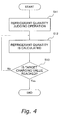
- FIG. 4 is a flowchart of the automatic refrigerant charging operation.
- the refrigerant circuit 10 When a command to start the automatic refrigerant charging operation is issued, the refrigerant circuit 10, with the four-way switching valve 22 of the outdoor unit 2 in the state represented by the solid lines in Figure 1 , becomes a state where the indoor expansion valves 41 and 51 of the indoor units 4 and 5 and the outdoor expansion valve 38 are opened. Then, the compressor 21, the outdoor fan 28, and the indoor fans 43 and 53 are started, and the cooling operation is forcibly performed in all of the indoor units 4 and 5 (hereinafter referred to as "all indoor unit operation").
- the high-pressure gas refrigerant compressed and discharged in the compressor 21 flows along a flow path from the compressor 21 to the outdoor heat exchanger 23 that functions as a condenser (see the portion from the compressor 21 to the outdoor heat exchanger 23 in the hatching area indicated by the diagonal line in Figure 5 ); the high-pressure refrigerant that undergoes phase-change from a gas state to a liquid state by heat exchange with the outdoor air flows in the outdoor heat exchanger 23 that functions as a condenser (see the portion corresponding to the outdoor heat exchanger 23 in the hatching area indicated by the diagonal line and the black-lacquered hatching area in Figure 5 ); the high-pressure liquid refrigerant flows along a flow path from the outdoor heat exchanger 23 to the indoor expansion valves 41 and 51 including the outdoor expansion valve 38, the portion corresponding to the main refrigerant circuit side of the subcooler 25 and the liquid refrigerant communication pipe 6, and a flow path from the outdoor heat exchange
- the indoor expansion valves 41 and 51 are controlled such that the superheat degree SHr of the indoor heat exchangers 42 and 52 that function as evaporators becomes constant (hereinafter referred to as "super heat degree control”); the operation capacity of the compressor 21 is controlled such that an evaporation pressure Pe becomes constant (hereinafter referred to as “evaporation pressure control”); the air flow rate Wo of outdoor air supplied to the outdoor heat exchanger 23 by the outdoor fan 28 is controlled such that a condensation pressure Pc of the refrigerant in the outdoor heat exchanger 23 becomes constant (hereinafter referred to as “condensation pressure control”); the operation capacity of the subcooler 25 is controlled such that the temperature of the refrigerant sent from the subcooler 25 to the indoor expansion valves 41 and 51 becomes constant (hereinafter referred to as "liquid pipe temperature control”); and the air flow rate Wr of room air supplied to the
- the reason to perform the evaporation pressure control is that the evaporation pressure Pe of the refrigerant in the indoor heat exchangers 42 and 52 that function as evaporators is greatly affected by the refrigerant quantity in the indoor heat exchangers 42 and 52 where low-pressure refrigerant flows while undergoing a phase change from a gas-liquid two-phase state to a gas state as a result of heat exchange with the room air (see the portions corresponding to the indoor heat exchangers 42 and 52 in the area indicated by the lattice hatching and hatching indicated by the diagonal line in Figure 5 , which is hereinafter referred to as "evaporator portion C").
- the control of the evaporation pressure Pe by the compressor 21 in the present embodiment is achieved in the following manner: the refrigerant temperature (which corresponds to the evaporation temperature Te) detected by the liquid side temperature sensors 44 and 54 of the indoor heat exchangers 42 and 52 is converted to saturation pressure; the operation capacity of the compressor 21 is controlled such that the saturation pressure becomes constant at a target low pressure Pes (in other words, the control to change the rotation frequency Rm of the motor 21a is performed); and then a refrigerant circulation flow rate Wc flowing in the refrigerant circuit 10 is increased or decreased.
- the refrigerant temperature which corresponds to the evaporation temperature Te
- the operation capacity of the compressor 21 is controlled such that the saturation pressure becomes constant at a target low pressure Pes (in other words, the control to change the rotation frequency Rm of the motor 21a is performed)
- a refrigerant circulation flow rate Wc flowing in the refrigerant circuit 10 is increased or decreased.
- the operation capacity of the compressor 21 may be controlled such that the suction pressure Ps of the compressor 21 detected by the suction pressure sensor 29, which is the operation state quantity equivalent to the pressure of the refrigerant at the evaporation pressure Pe of the refrigerant in the indoor heat exchangers 42 and 52, becomes constant at the target low pressure Pes, or the saturation temperature (which corresponds to the evaporation temperature Te) corresponding to the suction pressure Ps becomes constant at a target low pressure Tes.
- the operation capacity of the compressor 21 may be controlled such that the refrigerant temperature (which corresponds to the evaporation temperature Te) detected by the liquid side temperature sensors 44 and 54 of the indoor heat exchangers 42 and 52 becomes constant at the target low pressure Tes.
- gas refrigerant distribution portion D the state of the refrigerant flowing in the refrigerant pipes from the indoor heat exchangers 42 and 52 to the compressor 21 including the gas refrigerant communication pipe 7 and the accumulator 24 (see the portion from the indoor heat exchangers 42 and 52 to the compressor 21 in the hatching area indicated by the diagonal line in Figure 5 , which is hereinafter referred to as "gas refrigerant distribution portion D") becomes stabilized, creating a state where the refrigerant quantity in the gas refrigerant distribution portion D changes mainly by the evaporation pressure Pe (i.e., the suction pressure Ps), which is the operation state quantity equivalent to the pressure of the refrigerant in the gas refrigerant distribution portion D.
- the evaporation pressure Pe i.e., the suction pressure Ps
- the reason to perform the condensation pressure control is that the condensation pressure Pc of the refrigerant is greatly affected by the refrigerant quantity in the outdoor heat exchanger 23 where high-pressure refrigerant flows while undergoing a phase change from a gas state to a liquid state as a result of heat exchange with the outdoor air (see the portions corresponding to the outdoor heat exchanger 23 in the area indicated by the diagonal line hatching and the black hatching in Figure 5 , which is hereinafter referred to as "condenser portion A").
- the condensation pressure Pc of the refrigerant in the condenser portion A greatly changes due to the effect of the outdoor temperature Ta.
- the air flow rate Wo of the room air supplied from the outdoor fan 28 to the outdoor heat exchanger 23 is controlled by the motor 28a, and thereby the condensation pressure Pc of the refrigerant in the outdoor heat exchanger 23 is maintained constant and the state of the refrigerant flowing in the condenser portion A is stabilized, creating a state where the refrigerant quantity in condenser portion A changes mainly by a subcooling degree SCo at the liquid side of the outdoor heat exchanger 23 (hereinafter regarded as the outlet of the outdoor heat exchanger 23 in the description regarding the refrigerant quantity judging operation).
- the discharge pressure Pd of the compressor 21 detected by the discharge pressure sensor 30, which is the operation state quantity equivalent to the condensation pressure Pc of the refrigerant in the outdoor heat exchanger 23, or the temperature of the refrigerant flowing through the outdoor heat exchanger 23 (i.e., the condensation temperature Tc) detected by the heat exchanger temperature sensor 33 is used.
- the high-pressure liquid refrigerant flows along a flow path from the outdoor heat exchanger 23 to the indoor expansion valves 41 and 51 including the outdoor expansion valve 38, the portion on the main refrigerant circuit side of the subcooler 25, and the liquid refrigerant communication pipe 6 and a flow path from the outdoor heat exchanger 23 to the bypass expansion valve 62 of the bypass refrigerant circuit 61; the pressure of the refrigerant in the portions from the outdoor heat exchanger 23 to the indoor expansion valves 41 and 51 and to the bypass expansion valve 62 (see the area indicated by the black hatching in Figure 5 , which is hereinafter referred to as "liquid refrigerant distribution portion B") also becomes stabilized; and the liquid refrigerant distribution portion B is sealed by the liquid refrigerant, thereby becoming a stable state.
- the reason to perform the liquid pipe temperature control is to prevent a change in the density of the refrigerant in the refrigerant pipes from the subcooler 25 to the indoor expansion valves 41 and 51 including the liquid refrigerant communication pipe 6 (see the portion from the subcooler 25 to the indoor expansion valves 41 and 51 in the liquid refrigerant distribution portion B shown in Figure 5 ).
- Performance of the subcooler 25 is controlled by increasing or decreasing the flow rate of the refrigerant flowing in the bypass refrigerant circuit 61 such that the refrigerant temperature Tlp detected by the liquid pipe temperature sensor 35 disposed at the outlet on the main refrigerant circuit side of the subcooler 25 becomes constant at a target liquid pipe temperature Tlps, and by adjusting the quantity of heat exchange between the refrigerant flowing through the main refrigerant circuit side and the refrigerant flowing through the bypass refrigerant circuit side of the subcooler 25.
- the flow rate of the refrigerant flowing in the bypass refrigerant circuit 61 is increased or decreased by adjustment of the opening degree of the bypass expansion valve 62. In this way, the liquid pipe temperature control is achieved in which the refrigerant temperature in the refrigerant pipes from the subcooler 25 to the indoor expansion valves 41 and 51 including the liquid refrigerant communication pipe 6 becomes constant.
- the reason to perform the superheat degree control is because the refrigerant quantity in the evaporator portion C greatly affects the quality of wet vapor of the refrigerant at the outlets of the indoor heat exchangers 42 and 52.
- the superheat degree SHr of the refrigerant at the outlets of the indoor heat exchangers 42 and 52 is controlled such that the superheat degree SHr of the refrigerant at the gas sides of the indoor heat exchangers 42 and 52 (hereinafter regarded as the outlets of the indoor heat exchangers 42 and 52 in the description regarding the refrigerant quantity judging operation) becomes constant at the target superheat degree SHrs (in other words, the gas refrigerant at the outlets of the indoor heat exchangers 42 and 52 is in a superheat state) by controlling the opening degree of the indoor expansion valves 41 and 51, and thereby the state of the refrigerant flowing in the evaporator portion C is stabilized.
- the state of the refrigerant circulating in the refrigerant circuit 10 becomes stabilized, and the distribution of the refrigerant quantity in the refrigerant circuit 10 becomes constant. Therefore, when refrigerant starts to be charged into the refrigerant circuit 10 by additional refrigerant charging, which is subsequently performed, it is possible to create a state where a change in the refrigerant quantity in the refrigerant circuit 10 mainly appears as a change of the refrigerant quantity in the outdoor heat exchanger 23 (hereinafter this operation is referred to as "refrigerant quantity judging operation").
- Such control as described above is performed as the process in Step S11 by the controller 8 (more specifically, by the indoor side controllers 47 and 57, the outdoor side controller 37, and the transmission line 8a that connects between the controllers 37, 47 and 57) that functions as refrigerant quantity judging operation controlling means for performing the refrigerant quantity judging operation.
- Step S11 when refrigerant is not charged in advance in the outdoor unit 2, it is necessary prior to Step S11 to charge refrigerant until the refrigerant quantity reaches a level where constituent equipment will not abnormally stop during the above described refrigerant quantity judging operation.
- the controller 8 that functions as refrigerant quantity calculating means calculates the refrigerant quantity in the refrigerant circuit 10 from the operation state quantity of constituent equipment or refrigerant flowing in the refrigerant circuit 10 during additional refrigerant charging in Step S12.
- the refrigerant quantity calculating means divides the refrigerant circuit 10 into a plurality of portions, calculates the refrigerant quantity for each divided portion, and thereby calculates the refrigerant quantity in the refrigerant circuit 10. More specifically, a relational expression between the refrigerant quantity in each portion and the operation state quantity of constituent equipment or refrigerant flowing in the refrigerant circuit 10 is set for each divided portion, and the refrigerant quantity in each portion can be calculated by using these relational expressions.
- the refrigerant circuit 10 is divided into the following portions and a relational expression is set for each portion: a portion corresponding to the compressor 21 and a portion from the compressor 21 to the outdoor heat exchanger 23 including the four-way switching valve 22 (not shown in Figure 5 ) (hereinafter referred to as "high-pressure gas pipe portion E"); a portion corresponding to the outdoor heat exchanger 23 (i.e., the condenser portion A); a portion from the outdoor heat exchanger 23 to the subcooler 25 and an inlet side half of the portion corresponding to the main refrigerant circuit side of the subcooler 25 in the liquid ref
- the volume Vog1 of the high-pressure gas pipe portion E is a value that is known prior to installation of the outdoor unit 2 at the installation location and is stored in advance in the memory of the controller 8.
- a density pd of the refrigerant in the high-pressure gas pipe portion E is obtained by converting the discharge temperature Td and the discharge pressure Pd.
- the compressor discharge superheat degree SHm is a superheat degree of the refrigerant at the discharge side of the compressor, and is obtained by converting the discharge pressure Pd to refrigerant saturation temperature and subtracting this refrigerant saturation temperature from the discharge temperature Td.
- a saturated liquid density pc of the refrigerant is obtained by converting the condensation temperature Tc.
- a density pco of the refrigerant at the outlet of the outdoor heat exchanger 23 is obtained by converting the condensation pressure Pc is obtained by converting the condensation temperature Tc and the refrigerant temperature Tco.
- the volume Vol1 of the high-pressure liquid pipe portion B1 is a value that is known prior to installation of the outdoor unit 2 at the installation location and is stored in advance in the memory of the controller 8.
- the volume Vol2 of the low temperature liquid pipe portion B2 is a value that is known prior to installation of the outdoor unit 2 at the installation location and is stored in advance in the memory of the controller 8.
- the density ⁇ lp of the refrigerant in the low temperature liquid pipe portion B2 is the density of the refrigerant at the outlet of the subcooler 25, and is obtained by converting the condensation pressure Pc and the refrigerant temperature Tlp at the outlet of the subcooler 25.
- the volume Vlp of the liquid refrigerant communication pipe 6 because the liquid refrigerant communication pipe 6 is a refrigerant pipe arranged on site when installing the air conditioner 1 at an installation location such as a building, a value calculated on site from the information regarding the length, pipe diameter and the like is input, or information regarding the length, pipe diameter and the like is input on site and the controller 8 calculates the volume Vlp from the input information of the liquid refrigerant communication pipe 6. Or, as described below, the volume Vlp is calculated by using the operation results of the pipe volume judging operation.
- the parameters kr1 to kr5 in the above described relational expression are derived from a regression analysis of results of tests and detailed simulations and are stored in advance in the memory of the controller 8.
- the relational expression for the refrigerant quantity Mr is set for each of the two indoor units 4 and 5, and the entire refrigerant quantity in the indoor unit portion F is calculated by adding the refrigerant quantity Mr in the indoor unit 4 and the refrigerant quantity Mr in the indoor unit 5.
- relational expressions having parameters kr1 to kr5 with different values will be used when the model and/or capacity is different between the indoor unit 4 and the indoor unit 5.
- the volume Vgp of the gas refrigerant communication pipe 7 is a refrigerant pipe arranged on site when installing the air conditioner 1 at an installation location such as a building
- a value calculated on site from the information regarding the length, pipe diameter and the like is input, or information regarding the length, pipe diameter and the like is input on site and the controller 8 calculates the volume Vgp from the input information of the gas refrigerant communication pipe 7.
- the volume Vgp is calculated by using the operation results of the pipe volume judging operation.
- the density pgp of the refrigerant in the gas refrigerant communication pipe portion G is an average value between a density ps of the refrigerant at the suction side of the compressor 21 and a density peo of the refrigerant at the outlets of the indoor heat exchangers 42 and 52 (i.e., the inlet of the gas refrigerant communication pipe 7).
- the density ps of the refrigerant is obtained by converting the suction pressure Ps and the suction temperature Ts
- a density peo of the refrigerant is obtained by converting the evaporation pressure Pe, which is a converted value of the evaporation temperature Te, and an outlet temperature Teo of the indoor heat exchangers 42 and 52.
- the volume Vog2 of the low-pressure gas pipe portion H is a value that is known prior to shipment to the installation location and is stored in advance in the memory of the controller 8.
- the volume Vob of the bypass circuit portion I is a value that is known prior to installation of the outdoor unit 2 at the installation location and is stored in advance in the memory of the controller 8.
- the saturated liquid density pe at the portion corresponding to the bypass circuit side of the subcooler 25 is obtained by converting the suction pressure Ps or the evaporation temperature Te.
- one outdoor unit 2 is provided.
- the refrigerant quantity in the outdoor unit such as Mog1, Mc, Mol1, Mol2, Mog2, and Mob
- the relational expression for the refrigerant quantity in each portion is set for each of the plurality of outdoor units, and the entire refrigerant quantity in the outdoor units is calculated by adding the refrigerant quantity in each portion of the plurality of the outdoor units.
- relational expressions for the refrigerant quantity in each portion having parameters with different values will be used when a plurality of outdoor units with different models and capacities are connected.
- the refrigerant quantity in each portion is calculated from the operation state quantity of constituent equipment or refrigerant flowing in the refrigerant circuit 10 in the refrigerant quantity judging operation, and thereby the refrigerant quantity in the refrigerant circuit 10 can be calculated.
- the refrigerant quantity in each portion is calculated from the operation state quantity during refrigerant charging by using the relational expressions for each portion in the refrigerant circuit 10. More specifically, a refrigerant quantity Mo in the outdoor unit 2 and the refrigerant quantity Mr in each of the indoor units 4 and 5 (i.e., the refrigerant quantity in each portion in the refrigerant circuit 10 excluding the refrigerant communication pipes 6 and 7) necessary for judgment of the adequacy of the refrigerant quantity in the below described Step S13 are calculated.
- the refrigerant quantity Mo in the outdoor unit 2 is calculated by adding Mog1, Mc, Mol1, Mol2, Mog2, and Mob described above, each of which is the refrigerant quantity in each portion in the outdoor unit 2.
- Step S12 is performed by the controller 8 that functions as the refrigerant quantity calculating means for calculating the refrigerant quantity in each portion in the refrigerant circuit 10 from the operation state quantity of constituent equipment or refrigerant flowing in the refrigerant circuit 10 in the automatic refrigerant charging operation.
- the refrigerant quantity in the refrigerant circuit 10 gradually increases.
- the refrigerant quantity that should be charged into the refrigerant circuit 10 after additional refrigerant charging cannot be prescribed as the refrigerant quantity in the entire refrigerant circuit 10.
- the focus is placed only on the outdoor unit 2 and the indoor units 4 and 5 (i.e., the refrigerant circuit 10 excluding the refrigerant communication pipes 6 and 7), it is possible to know in advance the optimal refrigerant quantity in the outdoor unit 2 in the normal operation mode by tests and detailed simulations.
- additional refrigerant can be charged by the following manner: a value of this refrigerant quantity is stored in advance in the memory of the controller 8 as a target charging value Ms; the refrigerant quantity Mo in the outdoor unit 2 and a refrigerant quantity Mr in the indoor units 4 and 5 are calculated from the operation state quantity of constituent equipment or refrigerant flowing in the refrigerant circuit 10 in the automatic refrigerant charging operation by using the above described relational expressions; and additional refrigerant is charged until a value of the refrigerant quantity obtained by adding the refrigerant quantity Mo and the refrigerant quantity Mr reaches the target charging value Ms.
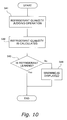
- Step S 13 is a process to judge the adequacy of the refrigerant quantity charged into the refrigerant circuit 10 by additional refrigerant charging by judging whether or not the refrigerant quantity, which is obtained by adding the refrigerant quantity Mo in the outdoor unit 2 and the refrigerant quantity Mr in the indoor units 4 and 5 in the automatic refrigerant charging operation, has reached the target charging value Ms.
- Step S 13 when a value of the refrigerant quantity obtained by adding the refrigerant quantity Mo in the outdoor unit 2 and the refrigerant quantity Mr in the indoor units 4 and 5 is smaller than the target charging value Ms and additional refrigerant charging has not been completed, the process in Step S13 is repeated until the target charging value Ms is reached.
- Step S 13 when a value of the refrigerant quantity obtained by adding the refrigerant quantity Mo in the outdoor unit 2 and the refrigerant quantity Mr in the indoor units 4 and 5 reaches the target charging value Ms, additional refrigerant charging is completed, and Step S 1 as the automatic refrigerant charging operation process is completed.
- the target charging value Ms may be set as a value corresponding to only the refrigerant quantity Mo in the outdoor unit 2 but not the outdoor unit 2 and the indoor units 4 and 5, or may be set as a value corresponding to the refrigerant quantity Mc in the outdoor heat exchanger 23, and additional refrigerant may be charged until the target charging value Ms is reached.
- Step S 13 the process in Step S 13 is performed by the controller 8 that functions as the refrigerant quantity judging means for judging the adequacy of the refrigerant quantity in the refrigerant circuit 10 in the refrigerant quantity judging operation of the automatic refrigerant charging operation (i.e., for judging whether or not the refrigerant quantity has reached the target charging value Ms).
- Step S1 When the above described automatic refrigerant charging operation in Step S1 is completed, the process proceeds to the pipe volume judging operation in Step S2.
- the process from Step S21 to Step S25 as shown in Figure 6 is performed by the controller 8.
- Figure 6 is a flowchart of the pipe volume judging operation.
- Step S21 as is the case with the above described refrigerant quantity judging operation in Step S11 of the automatic refrigerant charging operation, the pipe volume judging operation for the liquid refrigerant communication pipe 6, including the all indoor unit operation, condensation pressure control, liquid pipe temperature control, superheat degree control, and evaporation pressure control, is performed.
- the target liquid pipe temperature Tlps of the temperature Tlp of the refrigerant at the outlet on the main refrigerant circuit side of the subcooler 25 in the liquid pipe temperature control is regarded as a first target value Tlps1
- the state where the refrigerant quantity judging operation is stable at this first target value Tlps1 is regarded as a first state (see the refrigerating cycle indicated by the lines including the dotted lines in Figure 7 ).
- Figure 7 is a Mollier diagram to show the refrigerating cycle of the air conditioner 1 in the pipe volume judging operation for the liquid refrigerant communication pipe.
- the first state where the temperature Tlp of the refrigerant at the outlet on the main refrigerant circuit side of the subcooler 25 in liquid pipe temperature control is stable at the first target value Tlps1 is switched to a second state (see the refrigerating cycle indicated by the solid lines in Figure 7 ) where the target liquid pipe temperature Tlps is changed to a second target value Tlps2 different from the first target value Tlps1 and stabilized without changing the conditions for other equipment controls, i.e., the conditions for the condensation pressure control, superheat degree control, and evaporation pressure control (i.e., without changing the target superheat degree SHrs and the target low pressure Tes).
- the second target value Tlps2 is a temperature higher than the first target value Tlps1.
- the conditions for other equipment controls other than the liquid pipe temperature control are not changed, and therefore the refrigerant quantity Mog1 in the high-pressure gas pipe portion E, the refrigerant quantity Mog2 in the low-pressure gas pipe portion H, and the refrigerant quantity Mgp in the gas refrigerant communication pipe portion G are maintained substantially constant, and the refrigerant whose quantity has decreased in the liquid refrigerant communication pipe portion B3 will move to the condenser portion A, the high temperature liquid pipe portion B1, the low temperature liquid pipe portion B2, the indoor unit portion F, and the bypass circuit portion I.
- the refrigerant quantity Mc in the condenser portion A, the refrigerant quantity Mol1 in the high temperature liquid pipe portion B1, the refrigerant quantity Mol2 in the low temperature liquid pipe portion B2, the refrigerant quantity Mr in the indoor unit portion F, and the refrigerant quantity Mob in the bypass circuit portion I will increase by the quantity of the refrigerant that has decreased in the liquid refrigerant communication pipe portion B3.
- Such control as described above is performed as the process in Step S21 by the controller 8 (more specifically, by the indoor side controllers 47 and 57, the outdoor side controller 37, and the transmission line 8a that connects between the controllers 37, 47 and 57) that functions as pipe volume judging operation controlling means for performing the pipe volume judging operation to calculate the refrigerant quantity Mlp of the liquid refrigerant communication pipe 6.
- Step S22 the volume Vlp of the liquid refrigerant communication pipe 6 is calculated by utilizing a phenomenon that the refrigerant quantity in the liquid refrigerant communication pipe portion B3 decreases and the refrigerant whose quantity has decreased moves to other portions in the refrigerant circuit 10 because of the change from the first state to the second state.
- this ⁇ Mlp value is divided by a density change quantity ⁇ lp of the refrigerant between the first state and the second state in the liquid refrigerant communication pipe 6, and thereby the volume Vlp of the liquid refrigerant communication pipe 6 can be calculated.
- the refrigerant quantity Mog1 and the refrigerant quantity Mog2 may be included in the above described function expression.
- Vlp ⁇ Mlp / ⁇ lp
- ⁇ Mc, ⁇ Mol1, ⁇ Mol2, ⁇ Mr, and ⁇ Mob can be obtained by calculating the refrigerant quantity in the first state and the refrigerant quantity in the second state by using the above described relational expression for each portion in the refrigerant circuit 10 and further by subtracting the refrigerant quantity in the first state from the refrigerant quantity in the second state.
- the density change quantity ⁇ lp can be obtained by calculating the density of the refrigerant at the outlet of the subcooler 25 in the first state and the density of the refrigerant at the outlet of the subcooler 25 in the second state and further by subtracting the density of the refrigerant in the first state from the density of the refrigerant in the second state.
- the volume Vlp of the liquid refrigerant communication pipe 6 can be calculated from the operation state quantity of constituent equipment or refrigerant flowing in the refrigerant circuit 10 in the first and second states.
- the state is changed such that the second target value Tlps2 in the second state becomes a temperature higher than the first target value Tlps1 in the first state and therefore the refrigerant in the liquid refrigerant communication pipe portion B3 is moved to other portions in order to increase the refrigerant quantity in the other portions; thereby the volume Vlp in the liquid refrigerant communication pipe 6 is calculated from the increased quantity.
- the state may be changed such that the second target value Tlps2 in the second state becomes a temperature lower than the first target value Tlps1 in the first state and therefore the refrigerant is moved from other portions to the liquid refrigerant communication pipe portion B3 in order to decrease the refrigerant quantity in the other portions; thereby the volume Vlp in the liquid refrigerant communication pipe 6 is calculated from the decreased quantity.
- Step S22 is performed by the controller 8 that functions as the pipe volume calculating means for the liquid refrigerant communication pipe, which calculates the volume Vlp of the liquid refrigerant communication pipe 6 from the operation state quantity of constituent equipment or refrigerant flowing in the refrigerant circuit 10 in the pipe volume judging operation for the liquid refrigerant communication pipe 6.
- Step S23 the pipe volume judging operation for the gas refrigerant communication pipe 7, including the all indoor unit operation, condensation pressure control, liquid pipe temperature control, superheat degree control, and evaporation pressure control, is performed in Step S23.
- the target low pressure Pes of the suction pressure Ps of the compressor 21 in the evaporation pressure control is regarded as a first target value Pes1
- the state where the refrigerant quantity judging operation is stable at this first target value Pes1 is regarded as a first state (see the refrigerating cycle indicated by the lines including the dotted lines in Figure 8 ).
- Figure 8 is a Mollier diagram to show the refrigerating cycle of the air conditioner 1 in the pipe volume judging operation for the gas refrigerant communication pipe.
- the first state where the target low pressure Pes of the suction pressure Ps in the compressor 21 in evaporation pressure control is stable at the first target value Pes1 is switched to a second state (see the refrigerating cycle indicated by only the solid lines in Figure 8 ) where the target low pressure Pes is changed to a second target value Pes2 different from the first target value Pes1 and stabilized without changing the conditions for other equipment controls, i.e., without changing the conditions for the liquid pipe temperature control, the condensation pressure control, and the superheat degree control (i.e., without changing target liquid pipe temperature Tlps and target superheat degree SHrs).
- the second target value Pes2 is a pressure lower than the first target value Pes1.
- the density of the refrigerant in the gas refrigerant communication pipe 7 decreases, and therefore the refrigerant quantity Mgp in the gas refrigerant communication pipe portion G in the second state decreases compared to the refrigerant quantity in the first state. Then, the refrigerant whose quantity has decreased in the gas refrigerant communication pipe portion G will move to other portions in the refrigerant circuit 10.
- the conditions for other equipment controls other than the evaporation pressure control are not changed, and therefore the refrigerant quantity Mog1 in the high pressure gas pipe portion E, the refrigerant quantity Mol1 in the high-temperature liquid pipe portion B1, the refrigerant quantity Mol2 in the low temperature liquid pipe portion B2, and the refrigerant quantity Mlp in the liquid refrigerant communication pipe portion B3 are maintained substantially constant, and the refrigerant whose quantity has decreased in the gas refrigerant communication pipe portion G will move to the low-pressure gas pipe portion H, the condenser portion A, the indoor unit portion F, and the bypass circuit portion I.
- the refrigerant quantity Mog2 in the low-pressure gas pipe portion H, the refrigerant quantity Mc in the condenser portion A, the refrigerant quantity Mr in the indoor unit portion F, and the refrigerant quantity Mob in the bypass circuit portion I will increase by the quantity of the refrigerant that has decreased in the gas refrigerant communication pipe portion G.
- Such control as described above is performed as the process in Step S23 by the controller 8 (more specifically, by the indoor side controllers 47 and 57, the outdoor side controller 37, and the transmission line 8a that connects between the controllers 37 and 47, and 57) that functions as the pipe volume judging operation controlling means for performing the pipe volume judging operation to calculate the volume Vgp of the gas refrigerant communication pipe 7.
- Step S24 the volume Vgp of the gas refrigerant communication pipe 7 is calculated by utilizing a phenomenon that the refrigerant quantity in the gas refrigerant communication pipe portion G decreases and the refrigerant whose quantity has decreased moves to other portions in the refrigerant circuit 10 because of the change from the first state to the second state.
- this ⁇ Mgp value is divided by a density change quantity ⁇ gp of the refrigerant between the first state and the second state in the gas refrigerant communication pipe 7, and thereby the volume Vgp of the gas refrigerant communication pipe 7 can be calculated.
- the refrigerant quantity Mog1, the refrigerant quantity Mol1, and the refrigerant quantity Mol2 may be included in the above described function expression.
- Vgp ⁇ Mgp / ⁇ gp
- ⁇ mc, ⁇ Mog2, ⁇ Mr and ⁇ Mob can be obtained by calculating the refrigerant quantity in the first state and the refrigerant quantity in the second state by using the above described relational expression for each portion in the refrigerant circuit 10 and further by subtracting the refrigerant quantity in the first state from the refrigerant quantity in the second state.
- the density change quantity ⁇ gp can be obtained by calculating an average density between the density ps of the refrigerant at the suction side of the compressor 21 in the first state and the density peo of the refrigerant at the outlets of the indoor heat exchangers 42 and 52 in the first state and by subtracting the average density in the first state from the average density in the second state.
- the volume Vgp of the gas refrigerant communication pipe 7 can be calculated from the operation state quantity of constituent equipment or refrigerant flowing in the refrigerant circuit 10 in the first and second states.
- the state is changed such that the second target value Pes2 in the second state becomes a pressure lower than the first target value Pes1 in the first state and therefore the refrigerant in the gas refrigerant communication pipe portion G is moved to other portions in order to increase the refrigerant quantity in the other portions; thereby the volume Vlp of the gas refrigerant communication pipe 7 is calculated from the increased quantity.
- the state may be changed such that the second target value Pes2 in the second state becomes a pressure higher than the first target value Pes 1 in the first state and therefore the refrigerant is moved from other portions to the gas refrigerant communication pipe portion G in order to decrease the refrigerant quantity in the other portions; thereby the volume Vlp in the gas refrigerant communication pipe 7 is calculated from the decreased quantity.
- Step S24 is performed by the controller 8 that functions as the pipe volume calculating means for the gas refrigerant communication pipe, which calculates the volume Vgp of the gas refrigerant communication pipe 7 from the operation state quantity of constituent equipment or refrigerant flowing in the refrigerant circuit 10 in the pipe volume judging operation for the gas refrigerant communication pipe 7.
- Step S25 is performed to judge whether or not a result of the pipe volume judging operation is adequate, in other words, whether or not the volumes Vlp, Vgp of the refrigerant communication pipes 6 and 7 calculated by the pipe volume calculating means are adequate.
- Step S2 of the pipe volume judging operation is completed.
- the process for the pipe volume judging operation and volume calculation in Step S21 to Step S24 is performed again.
- Step S25 the process in Step S25 is performed by the controller 8 that functions as the adequacy judging means for judging whether or not a result of the above described pipe volume judging operation is adequate, in other words, whether or not the volumes Vlp, Vgp of the refrigerant communication pipes 6 and 7 calculated by the pipe volume calculating means are adequate.
- the pipe volume judging operation (Steps S21, S22) for the liquid refrigerant communication pipe 6 is first performed and then the pipe volume judging operation for the gas refrigerant communication pipe 7 (Steps S23, S24) is performed.
- the pipe volume judging operation for the gas refrigerant communication pipe 7 may be performed first.
- Step S25 when a result of the pipe volume judging operation in Steps S21 to S24 is judged to be inadequate for a plurality of times, or when it is desired to more simply judge the volumes Vlp, Vgp of the refrigerant communication pipes 6 and 7, although it is not shown in Figure 6 , for example, in Step S25, after a result of the pipe volume judging operation in Steps S21 to S24 is judged to be inadequate, it is possible to proceed to the process for estimating the lengths of the refrigerant communication pipes 6 and 7 from the pressure loss in the refrigerant communication pipes 6 and 7 and calculating the volumes Vlp, Vgp of the refrigerant communication pipes 6 and 7 from the estimated pipe lengths and an average volume ratio, thereby obtaining the volumes Vlp, Vgp of the refrigerant communication pipes 6 and 7.
- the pipe volume judging operation is performed to calculate the volumes Vlp, Vgp of the refrigerant communication pipes 6 and 7 is described on the premise that there is no information regarding the lengths, pipe diameters and the like of the refrigerant communication pipes 6 and 7 and the volumes Vlp, Vgp of the refrigerant communication pipes 6 and 7 are unknown.
- the pipe volume calculating means has a function to calculate the volumes Vlp, Vgp of the refrigerant communication pipes 6 and 7 by inputting information regarding the lengths, pipe diameters and the like of the refrigerant communication pipes 6 and 7, such function may be used together.
- the above described adequacy judging means may be used to judge whether or not the input information regarding the lengths, pipe diameters and the like of the refrigerant communication pipes 6 and 7 is adequate.
- Step S2 When the above described pipe volume judging operation in Step S2 is completed, the process proceeds to an initial refrigerant quantity judging operation in Step S3.
- the process in Step S31 and Step S32 shown in Figure 9 is performed by the controller 8.
- Figure 9 is a flowchart of the initial refrigerant quantity detection operation.
- Step S31 as is the case with the above described refrigerant quantity judging operation in Step S 11 of the automatic refrigerant charging operation, the refrigerant quantity judging operation, including the all indoor unit operation, condensation pressure control, liquid pipe temperature control, superheat degree control, and evaporation pressure control, is performed.
- the refrigerant quantity judging operation including the all indoor unit operation, condensation pressure control, liquid pipe temperature control, superheat degree control, and evaporation pressure control.
- values that are the same as the target values in the refrigerant quantity judging operation in Step S11 of the automatic refrigerant charging operation are used for the target liquid pipe temperature Tlps in the liquid pipe temperature control, the target superheat degree SHrs in the superheat degree control, and the target low pressure Pes in the evaporation pressure control.
- Step S31 the process in Step S31 is performed by the controller 8 that functions as the refrigerant quantity judging operation controlling means for performing the refrigerant quantity judging operation, including the all indoor unit operation, condensation pressure control, liquid pipe temperature control, superheat degree control, and evaporation pressure control.
- the refrigerant quantity in the refrigerant circuit 10 is calculated from the operation state quantity of constituent equipment or refrigerant flowing in the refrigerant circuit 10 in the initial refrigerant quantity judging operation in Step S32 by the controller 8 that functions as the refrigerant quantity calculating means while performing the above described refrigerant quantity judging operation.
- Calculation of the refrigerant quantity in the refrigerant circuit 10 is performed by using the above described relational expressions between the refrigerant quantity in each portion in the refrigerant circuit 10 and the operation state quantity of constituent equipment or refrigerant flowing in the refrigerant circuit 10.
- the volumes Vlp and Vgp of the refrigerant communication pipes 6 and 7, which were unknown at the time of after installation of constituent equipment of the air conditioner 1, have been calculated and the values thereof are known by the above described pipe volume judging operation.
- the refrigerant quantities Mlp, Mgp in the refrigerant communication pipes 6 and 7 can be calculated, and further by adding the refrigerant quantity in the other each portion, the initial refrigerant quantity in the entire refrigerant circuit 10 can be detected.
- This initial refrigerant quantity is used as a reference refrigerant quantity Mi of the entire refrigerant circuit 10, which serves as the reference for judging whether or not the refrigerant is leaking from the refrigerant circuit 10 in the below described refrigerant leak detection operation. Therefore, it is stored as a value of the operation state quantity in the memory of the controller 8 as state quantity storing means.
- Step S32 the process in Step S32 is performed by the controller 8 that functions as the refrigerant quantity calculating means for calculating the refrigerant quantity in each portion in the refrigerant circuit 10 from the operation state quantity of constituent equipment or refrigerant flowing in the refrigerant circuit 10 in the initial refrigerant quantity detecting operation.
- Figure 10 is a flowchart of the refrigerant leak detection operation mode.
- the normal operation mode when operation in the normal operation mode such as the above described cooling operation and heating operation has gone on for a certain period of time (for example, half a year to a year), the normal operation mode is automatically or manually switched to the refrigerant leak detection operation mode, and as is the case with the refrigerant quantity judging operation of the initial refrigerant quantity detection operation, the refrigerant quantity judging operation, including the all indoor unit operation, condensation pressure control, liquid pipe temperature control, superheat degree control, and evaporation pressure control, is performed.
- values that are the same as the target values in Step S31 of the refrigerant quantity judging operation of the initial refrigerant quantity detection operation are used for the target liquid pipe temperature Tlps in the liquid pipe temperature control, the target superheat degree SHrs in the superheat degree control, and the target low pressure Pes in the evaporation pressure control.
- this refrigerant quantity judging operation is performed for each time the refrigerant leak detection operation is performed. Even when the refrigerant temperature Tco at the outlet of the outdoor heat exchanger 23 fluctuates due to the different operating conditions, for example, such as when the condensation pressure Pc is different or when the refrigerant is leaking, the refrigerant temperature Tlp in the liquid refrigerant communication pipe 6 is maintained constant at the same target liquid pipe temperature Tlps by the liquid pipe temperature control.
- Step S41 the process in Step S41 is performed by the controller 8 that functions as the refrigerant quantity judging operation controlling means for performing the refrigerant quantity judging operation, including the all indoor unit operation, condensation pressure control, liquid pipe temperature control, superheat degree control, and evaporation pressure control.
- the refrigerant quantity in the refrigerant circuit 10 is calculated from the operation state quantity of constituent equipment or refrigerant flowing in the refrigerant circuit 10 in the refrigerant leak detection operation in Step S42 by the controller 8 that functions as the refrigerant quantity calculating means while performing the above described refrigerant quantity judging operation.
- Calculation of the refrigerant quantity in the refrigerant circuit 10 is performed by using the above described relational expression between the refrigerant quantity in each portion in the refrigerant circuit 10 and the operation state quantity of constituent equipment or refrigerant flowing in the refrigerant circuit 10.
- the volumes Vlp and Vgp of the refrigerant communication pipes 6 and 7, which were unknown at the time of after installation of constituent equipment of the air conditioner 1, have been calculated and the values thereof are known by the above described pipe volume judging operation.
- the refrigerant quantities Mlp, Mgp in the refrigerant communication pipes 6 and 7 can be calculated, and further by adding the refrigerant quantity in the other each portion, the refrigerant quantity M in the entire refrigerant circuit 10 can be calculated.
- the refrigerant temperature Tlp in the liquid refrigerant communication pipe 6 is maintained constant at the target liquid pipe temperature Tlps by the liquid pipe temperature control. Therefore, regardless the difference in the operating conditions for the refrigerant leak detection operation, the refrigerant quantity Mlp in the liquid refrigerant communication pipe portion B3 will be maintained constant even when the refrigerant temperature Tco at the outlet of the outdoor heat exchanger 23 changes.
- Step S42 is performed by the controller 8 that functions as the refrigerant quantity calculating means for calculating the refrigerant quantity at each portion in the refrigerant circuit 10 from the operation state quantity of constituent equipment or refrigerant flowing in the refrigerant circuit 10 in the refrigerant leak detection operation.
- the refrigerant quantity in the refrigerant circuit 10 decreases. Then, when the refrigerant quantity in the refrigerant circuit 10 decreases, mainly, a tendency of a decrease in the subcooling degree SC o at the outlet of the outdoor heat exchanger 23 appears. Along with this, the refrigerant quantity Mc in the outdoor heat exchanger 23 decreases, and the refrigerant quantities in other portions tend to be maintained substantially constant.
- the refrigerant quantity M of the entire refrigerant circuit 10 calculated in the above described Step S42 is smaller than the reference refrigerant quantity Mi detected in the initial refrigerant quantity detection operation when the refrigerant is leaking from the refrigerant circuit 10; whereas when the refrigerant is not leaking from the refrigerant circuit 10, the refrigerant quantity M is substantially the same as the reference refrigerant quantity Mi.
- Step S43 whether or not the refrigerant is leaking is judged in Step S43.
- Step S43 that the refrigerant is not leaking from the refrigerant circuit 10
- the refrigerant leak detection operation mode is finished.
- Step S43 when it is judged in Step S43 that the refrigerant is leaking from the refrigerant circuit 10, the process proceeds to Step S44, and a warning indicating that a refrigerant leak is detected is displayed on the warning display 9. Subsequently, the refrigerant leak detection operation mode is finished.
- Steps S42 to S44 the process from Steps S42 to S44 is performed by the controller 8 that functions as the refrigerant leak detection means, which is one of the refrigerant quantity judging means, and which detects whether or not the refrigerant is leaking by judging the adequacy of the refrigerant quantity in the refrigerant circuit 10 while performing the refrigerant quantity judging operation in the refrigerant leak detection operation mode.
- the controller 8 that functions as the refrigerant leak detection means, which is one of the refrigerant quantity judging means, and which detects whether or not the refrigerant is leaking by judging the adequacy of the refrigerant quantity in the refrigerant circuit 10 while performing the refrigerant quantity judging operation in the refrigerant leak detection operation mode.
- the controller 8 functions as the refrigerant quantity judging operation means, the refrigerant quantity calculating means, the refrigerant quantity judging means, the pipe volume judging operation means, the pipe volume calculating means, the adequacy judging means, and the state quantity storing means, and thereby configures the refrigerant quantity judging system for judging the adequacy of the refrigerant quantity charged into the refrigerant circuit 10.
- the air conditioner 1 in the present embodiment has the following characteristics.
- the refrigerant circuit 10 is divided into a plurality of portions, and the relational expression between the refrigerant quantity and the operation state quantity is set for each portion. Consequently, compared to the conventional case where a simulation of characteristics of a refrigerating cycle is performed, the calculation load can be reduced, and the operation state quantity that is important for calculation of the refrigerant quantity in each portion can be selectively incorporated as a variable of the relational expression, thus improving the calculation accuracy of the refrigerant quantity in each portion. As a result, the adequacy of the refrigerant quantity in the refrigerant circuit 10 can be judged with high accuracy.
- the controller 8 as the refrigerant quantity calculating means can quickly calculate the refrigerant quantity in each portion from the operation state quantity of constituent equipment or refrigerant flowing in the refrigerant circuit 10 in the automatic refrigerant charging operation in which the refrigerant is charged into the refrigerant circuit 10. Moreover, by using the calculated refrigerant quantity in each portion, the controller 8 as the refrigerant quantity judging means can judge with high accuracy whether or not the refrigerant quantity in the refrigerant circuit 10 (specifically, a value obtained by adding the refrigerant quantity Mo in the outdoor unit 2 and the refrigerant quantity Mr in the indoor units 4 and 5) has reached the target charging value Ms.
- the controller 8 can quickly calculate the initial refrigerant quantity as the reference refrigerant quantity Mi by calculating the refrigerant quantity in each portion from the operation state quantity of constituent equipment or refrigerant flowing in the refrigerant circuit 10 in the initial refrigerant quantity detection operation in which the initial refrigerant quantity after constituent equipment is installed or after the refrigerant is charged into the refrigerant circuit 10 is detected. Moreover, it is possible to detect the initial refrigerant quantity with high accuracy.
- the controller 8 can quickly calculate the refrigerant quantity in each portion from the operation state quantity of constituent equipment or refrigerant flowing in the refrigerant circuit 10 in the refrigerant leak detection operation in which whether or not there is a refrigerant leak from the refrigerant circuit 10 is judged. Moreover, the controller 8 can judge with high accuracy whether or not the refrigerant is leaking from the refrigerant circuit 10 by comparison between the calculated refrigerant quantity in each portion and the reference refrigerant quantity Mi that serves as a reference for judging whether or not the refrigerant is leaking.
- the refrigerant circuit 10 is divided into the refrigerant communication pipes 6 and 7 (i.e., the liquid refrigerant communication pipe portion B3 and the gas refrigerant communication pipe portion G) where the refrigerant quantity changes depending on conditions such as an installation location and the like and the portion other than the refrigerant communication pipes 6 and 7 (here, the outdoor unit 2 as the heat source unit and the indoor units 4 and 5 as the utilization units), and the relational expressions between the refrigerant quantity in each portion and the operation state quantity are set.
- the refrigerant communication pipes 6 and 7 i.e., the liquid refrigerant communication pipe portion B3 and the gas refrigerant communication pipe portion G
- the relational expressions for calculating the refrigerant quantity in the portion other than the refrigerant communication pipes 6 and 7 it is possible to use the relational expressions in which a calculation error due to the change in the refrigerant quantity in the refrigerant communication pipes 6 and 7 is not easily generated. As a result, the accuracy for judging the adequacy of the refrigerant quantity in the refrigerant circuit 10 can be further improved.
- the portion other than the refrigerant communication pipes 6 and 7 is divided into the outdoor unit 2 and the indoor units 4 and 5, and the relational expressions between the refrigerant quantity in each portion and the operation state quantity are set.
- the relational expressions separately provided for the outdoor unit 2 and the indoor units 4 and 5 can be used.
- the accuracy for judging the adequacy of the refrigerant quantity in the refrigerant circuit 10 can be further improved.
- the outdoor unit 2 is divided into the outdoor heat exchanger 23 as the heat source side heat exchanger (i.e., condenser portion A), and the portion other than the outdoor heat exchanger 23 (here, the high pressure gas pipe portion F, the high temperature liquid pipe portion B1, the low temperature liquid pipe portion B2, the low pressure gas pipe portion H, and the bypass circuit portion I), and the relational expressions between the refrigerant quantity in each portion and the operation state quantity are set.
- the heat source side heat exchanger i.e., condenser portion A
- the portion other than the outdoor heat exchanger 23 here, the high pressure gas pipe portion F, the high temperature liquid pipe portion B1, the low temperature liquid pipe portion B2, the low pressure gas pipe portion H, and the bypass circuit portion I
- the refrigerant circulation flow rate Wc or the operation state quantity (for example, the evaporation temperature Te, the condensation temperature Tc, or the like) equivalent to the refrigerant circulation flow rate Wc is included.
- the accuracy for judging the adequacy of the refrigerant quantity in the refrigerant circuit 10 can be further improved.
- the air flow rate Wr of the indoor fans 43 and 53 as the ventilation fans or the operation state quantity (for example, the tap of the fan or the like) equivalent to the air flow rate Wr is included.
- the accuracy for judging the adequacy of the refrigerant quantity in the refrigerant circuit 10 can be further improved.
- the subcooler 25 is disposed as the temperature adjustment mechanism capable of adjusting the temperature of the refrigerant sent from the outdoor heat exchanger 23 as a condenser to the indoor expansion valves 41 and 51 as expansion mechanisms. Performance of the subcooler 25 is controlled such that the temperature Tlp of the refrigerant sent from the subcooler 25 to the indoor expansion valves 41 and 51 as expansion mechanisms is maintained constant during the refrigerant quantity judging operation, thereby preventing a change in the density ⁇ lp of the refrigerant in the refrigerant pipes from the subcooler 25 to the indoor expansion valves 41 and 51.
- the effect of the temperature difference of the refrigerant as described above will remain only within the refrigerant pipes from the outlet of the outdoor heat exchanger 23 to the subcooler 25, and the error in judgment due to the difference in the temperature Tco of the refrigerant at the outlet of the outdoor heat exchanger 23 (i.e., the difference in the density of the refrigerant) can be reduced when judging the refrigerant quantity.
- the outdoor unit 2 as a heat source unit and the indoor units 4 and 5 as utilization units are interconnected via the liquid refrigerant communication pipe 6 and the gas refrigerant communication pipe 7, the lengths, pipe diameters and the like of the refrigerant communication pipes 6 and 7 that connect between the outdoor unit 2 and the indoor units 4 and 5 are different depending on conditions such as installation location.
- the difference in the refrigerant temperature Tco at the outlet of the outdoor heat exchanger 23 will be the difference in the temperature of the refrigerant in the liquid refrigerant communication pipe 6 that configures a large portion of the refrigerant pipes from the outlet of the outdoor heat exchanger 23 to the indoor expansion valves 41 and 51 and thus the error in judgment tends to increase.
- the initial refrigerant quantity detection operation in which the initial refrigerant quantity after constituent equipment is installed or after the refrigerant is charged into the refrigerant circuit 10 is detected, the initial refrigerant quantity can be detected with high accuracy.
- the refrigerant leak detection operation in which whether or not there is a refrigerant leak from the refrigerant circuit 10 is judged, whether or not there is a refrigerant leak from the refrigerant circuit 10 can be judged with high accuracy.
- a change in the density pgp of the refrigerant sent from the indoor heat exchangers 42 and 52 to the compressor 21 is prevented by controlling constituent equipment such that the pressure (for example, the suction pressure Ps and the evaporation pressure Pe) of the refrigerant sent from the indoor heat exchangers 42 and 52 as evaporators to the compressor 21 or the operation state quantity (for example, the evaporation temperature Te) equivalent to the aforementioned pressure becomes constant during the refrigerant quantity judging operation.
- the pressure for example, the suction pressure Ps and the evaporation pressure Pe
- the error in judgment due to the difference i.e., the difference in the density of the refrigerant
- the difference in the density of the refrigerant in the pressure of the refrigerant at the outlets of the indoor heat exchangers 42 and 52 or the operation state quantity equivalent to the aforementioned pressure can be reduced when judging the refrigerant quantity.
- the pipe volume judging operation is performed in which two states are created where the density of the refrigerant flowing in the refrigerant communication pipes 6 and 7 is different between the two states. Then, the increase/decrease quantity of the refrigerant between these two states is calculated from the refrigerant quantity in the portions other than the refrigerant communication pipes 6 and 7, and the increase/decrease quantity of the refrigerant is divided by the density change quantity of the refrigerant in the refrigerant communication pipes 6 and 7 between the first state and the second state, thereby the volumes of the refrigerant communication pipes 6 and 7 are calculated.
- the volumes of the refrigerant communication pipes 6 and 7 can be detected. Accordingly, the volumes of the refrigerant communication pipes 6 and 7 can be obtained while reducing the labor of inputting information of the refrigerant communication pipes 6 and 7.
- the adequacy of the refrigerant quantity in the refrigerant circuit 10 can be judged by using the volumes of the refrigerant communication pipes 6 and 7 calculated by the pipe volume calculating means and the operation state quantity of constituent equipment or refrigerant flowing in the refrigerant circuit 10. Therefore, even when the volumes of the refrigerant communication pipes 6 and 7 are unknown at the time of after installation of constituent equipment, the adequacy of the refrigerant quantity in the refrigerant circuit 10 can be judged with high accuracy.
- the refrigerant quantity in the refrigerant circuit 10 in the initial refrigerant quantity judging operation can be calculated by using the volumes of the refrigerant communication pipes 6 and 7 calculated by the pipe volume calculating means.
- the refrigerant quantity in the refrigerant circuit 10 in the refrigerant leak detection operation can be calculated by using the volumes of the refrigerant communication pipes 6 and 7 calculated by the pipe volume calculating means.
- the volume Vlp of the liquid refrigerant communication pipe 6 and the volume Vgp of the gas refrigerant communication pipe 7 are calculated from the information regarding the liquid refrigerant communication pipe 6 and the gas refrigerant communication pipe 7 (for example, operation results of the pipe volume judging operation and information regarding the lengths, pipe diameters and the like of the refrigerant communication pipes 6 and 7, which is input by the operator and the like). Then, based on the results obtained by calculating the volume Vlp of the liquid refrigerant communication pipe 6 and the volume Vgp of the gas refrigerant communication pipe 7, whether or not the information regarding the liquid refrigerant communication pipe 6 and the gas refrigerant communication pipe 7 used for the calculation is adequate is judged.
- the volume Vlp of the liquid refrigerant communication pipe 6 and the volume Vgp of the gas refrigerant communication pipe 7 can be accurately obtained; whereas when it is judged to be inadequate, it is possible to handle the situation by, for example, re-inputting appropriate information regarding the liquid refrigerant communication pipe 6 and the gas refrigerant communication pipe 7, re-performing the pipe volume judging operation, and the like.
- such judgment method is not to judge the adequacy by individually checking the volume Vlp of the liquid refrigerant communication pipe 6 and the volume Vgp of the gas refrigerant communication pipe 7 obtained by the calculation, but to judge the adequacy by checking whether or not the volume Vlp of the liquid refrigerant communication pipe 6 and the volume Vgp of the gas refrigerant communication pipe 7 satisfy a predetermined relation. Therefore, an appropriate judgment can be made which also takes into consideration a relative relation between the volume Vlp of the liquid refrigerant communication pipe 6 and the volume Vgp of the gas refrigerant communication pipe 7.
- the present invention is applied to an air conditioner capable of switching and performing the cooling operation and heating operation.
- the present invention may be applied to different types of air conditioners such as a cooling only air conditioner and the like.
- an example in which the present invention is applied to an air conditioner including a single outdoor unit is described.
- the present invention may be applied to an air conditioner including a plurality of outdoor units.
Landscapes
- Engineering & Computer Science (AREA)
- Physics & Mathematics (AREA)
- Mechanical Engineering (AREA)
- Thermal Sciences (AREA)
- General Engineering & Computer Science (AREA)
- Air Conditioning Control Device (AREA)
Abstract
Description
- The present invention relates to a function to judge the adequacy of the refrigerant quantity in a refrigerant circuit of an air conditioner. More specifically, the present invention relates to a function to judge the adequacy of the refrigerant quantity in a refrigerant circuit of an air conditioner configured by the interconnection of a compressor, a heat source side heat exchanger, an expansion mechanism, and a utilization side heat exchanger.
- Conventionally, an approach has been proposed in which a simulation of refrigeration cycle characteristics is performed and the excess or deficiency of the refrigerant quantity is judged by using a result of the calculation, in order to judge the excess or deficiency of the refrigerant quantity in a refrigerant circuit of an air conditioner (for example, see Patent Document 1).
-
JP-A Publication No. 2000-304388 - However, with the approach to judge the excess or deficiency of the refrigerant quantity through the simulation of refrigeration cycle characteristics as described above, an enormous amount of calculation is necessary. Also, typically, with a low-cost calculation device such as a microcomputer and the like installed in the air conditioner, the calculation time is long. In addition, the calculation itself might be impossible to be carried out.
- An object of the present invention is to judge the adequacy of the refrigerant quantity in the refrigerant circuit with high accuracy while reducing the calculation load.
- An air conditioner according to a first aspect of the present invention includes a refrigerant circuit, refrigerant quantity calculating means, and refrigerant quantity judging means. The refrigerant circuit is configured by the interconnection of a compressor, a heat source side heat exchanger, and a utilization side heat exchanger. The refrigerant quantity calculating means uses a relational expression between the refrigerant quantity in each portion of the refrigerant circuit when refrigerant circuit is divided into a plurality of portions and an operation state quantity of constituent equipment or refrigerant flowing in the refrigerant circuit in order to calculate the refrigerant quantity in each portion from the operation state quantity of constituent equipment or refrigerant flowing in the refrigerant circuit. The refrigerant quantity judging means uses the refrigerant quantity in each portion calculated by the refrigerant quantity calculating means in order to judge the adequacy of the refrigerant quantity in the refrigerant circuit.
- In this air conditioner, the refrigerant circuit is divided into a plurality of portions, and the relational expression between the refrigerant quantity in each portion and the operation state quantity is set. Consequently, compared to the conventional case where a simulation of refrigeration cycle characteristics is performed, the calculation load can be reduced, and an operation state quantity that is important for calculation of the refrigerant quantity in each portion can be selectively incorporated as a variable of the relational expression, thus improving the calculation accuracy of the refrigerant quantity in each portion. As a result, the adequacy of the refrigerant quantity in the refrigerant circuit can be judged with high accuracy. Here, the "operation state quantity of constituent equipment or refrigerant flowing in the refrigerant circuit" refers to state quantities such as the temperature, pressure, and the like of the refrigerant flowing in the refrigerant circuit and state quantities of equipment constituting the air conditioner.
- An air conditioner according to a second aspect of the present invention is the air conditioner according to the first aspect of the present invention, wherein the refrigerant circuit is configured by a heat source unit including the compressor and the heat source side heat exchanger; a utilization unit including the utilization side heat exchanger; and a refrigerant communication pipe that interconnects the heat source unit and the utilization unit. The relational expressions are separately set for the refrigerant communication pipe and a portion other than the refrigerant communication pipe as the refrigerant circuit is divided into these portions.
- In this air conditioner, the refrigerant circuit is divided into the refrigerant communication pipe where the refrigerant quantity changes depending on conditions such as an installation location and the like and the portion other than the refrigerant communication pipe, and the relational expressions between the refrigerant quantity in each portion and the operation state quantity are set. Thus, as the relational expression for calculating the refrigerant quantity in the portion other than the refrigerant communication pipe, it is possible to use the relational expressions in which a calculation error due to the change in the refrigerant quantity in the refrigerant communication pipe is not easily generated. As a result, the accuracy for judging the adequacy of the refrigerant quantity in the refrigerant circuit can be further improved.
- An air conditioner according to a third aspect of the present invention is the air conditioner according to the second aspect of the present invention, wherein the relational expressions are separately set for the heat source unit and the utilization unit as the portion other than the refrigerant communication pipe is divided into these portions.
- In this air conditioner, the portion other than the refrigerant communication pipe is divided into the heat source unit and the utilization unit, and the relational expressions between the refrigerant quantity in each portion and the operation state quantity are set. Thus, even when the heat source unit and the utilization unit are interconnected in various combinations, the relational expressions separately provided for the heat source unit and the utilization unit can be used. As a result, the accuracy for judging the adequacy of the refrigerant quantity in the refrigerant circuit can be further improved.
- An air conditioner according to a fourth aspect of the present invention is the air conditioner according to the third aspect of the present invention, wherein the relational expressions are separately set for the heat source side heat exchanger and a portion other than the heat source side heat exchanger as the heat source unit is divided into these portions. The relational expression set for the refrigerant quantity in the heat source side heat exchanger includes a refrigerant circulation flow rate or an operation state quantity equivalent to the refrigerant circulation flow rate as the operation state quantity of constituent equipment or refrigerant flowing in the refrigerant circuit.
- In this air conditioner, the heat source unit is divided into the heat source side heat exchanger and the portion other than the heat source side heat exchanger, and the relational expressions between the refrigerant quantity in each portion and the operation state quantity are set. Also, as the operation state quantity used in the relational expression for calculating the refrigerant quantity in the heat source side heat exchanger, a refrigerant circulation flow rate or an operation state quantity equivalent to the refrigerant circulation flow rate is included. Thus, it is possible to prevent a calculation error due to the difference in the refrigerant circulation flow rate from being easily generated. As a result, the accuracy for judging the adequacy of the refrigerant quantity in the refrigerant circuit can be further improved.
- An air conditioner according to a fifth aspect of the present invention is the air conditioner according to the third or fourth aspect of the present invention, wherein the utilization unit further includes a ventilation fan that supplies air to the utilization side heat exchanger. The relational expression set for the refrigerant quantity in the utilization unit includes an air flow rate of the ventilation fan or an operation state quantity equivalent to the air flow rate as the operation state quantity of constituent equipment or refrigerant flowing in the refrigerant circuit.
- In this air conditioner, as the operation state quantity used in the relational expression for calculating the refrigerant quantity in the utilization unit, an air flow rate of the ventilation fan or an operation state quantity equivalent to the air flow rate is included. Thus, it is possible to prevent a calculation error due to the difference in the air flow rate from being easily generated. As a result, the accuracy for judging the adequacy of the refrigerant quantity in the refrigerant circuit can be further improved.
- An air conditioner according to a sixth aspect of the present invention is the air conditioner according to any one of the first through fifth aspects of the present invention, wherein the refrigerant quantity calculating means uses the relational expressions in order to calculate the refrigerant quantity in each portion from the operation state quantity of constituent equipment or refrigerant flowing in the refrigerant circuit in an automatic refrigerant charging operation in which the refrigerant is charged into the refrigerant circuit. The refrigerant quantity judging means uses the refrigerant quantity in each portion calculated by the refrigerant quantity calculating means in order to judge whether or not the refrigerant quantity in the refrigerant circuit has reached a target charge value.
- In this air conditioner, during the automatic refrigerant charging operation, the refrigerant quantity can be quickly calculated, and moreover, whether or not the refrigerant quantity in the refrigerant circuit has reached the target charge value can be judged with high accuracy.
- An air conditioner according to a seventh aspect of the present invention is the air conditioner according to any one of the first through sixth aspects of the present invention, wherein the refrigerant quantity calculating means uses the relational expressions in order to calculate the refrigerant quantity in each portion from the operation state quantity of constituent equipment or refrigerant flowing in the refrigerant circuit in an initial refrigerant quantity detection operation in which the initial refrigerant quantity after constituent equipment is installed or after the refrigerant is charged into the refrigerant circuit is detected, and thereby detects the initial refrigerant quantity.
- In this air conditioner, during the initial refrigerant quantity detection operation, the refrigerant quantity can be quickly calculated, and moreover, the initial refrigerant quantity can be detected with high accuracy.
- An air conditioner according to an eighth aspect of the present invention is the air conditioner according to any one of the first through seventh aspects of the present invention, wherein the refrigerant quantity calculating means uses the relational expressions in order to calculate the refrigerant quantity in each portion from the operation state quantity of constituent equipment or refrigerant flowing in the refrigerant circuit in a refrigerant leak detection operation in which whether or not the refrigerant is leaking from the refrigerant circuit is judged. The refrigerant quantity judging means compares the refrigerant quantity in each portion calculated by the refrigerant quantity calculating means with a reference refrigerant quantity that serves as the reference for judging whether or not there is a leak, and thereby judges whether or not the refrigerant is leaking from the refrigerant circuit.
- In this air conditioner, during the refrigerant leak detection operation, the refrigerant quantity can be quickly calculated, and moreover, whether or not the refrigerant is leaking from the refrigerant circuit can be judged with high accuracy.
-
-
Figure 1 is a schematic configuration view of an air conditioner according to an embodiment of the present invention. -
Figure 2 is a control block diagram of the air conditioner. -
Figure 3 is a flowchart of a test operation mode. -
Figure 4 is a flowchart of an automatic refrigerant charging operation. -
Figure 5 is a schematic diagram to show a state of refrigerant flowing in a refrigerant circuit in a refrigerant quantity judging operation (illustrations of a four-way switching valve and the like are omitted). -
Figure 6 is a flowchart of a pipe volume judging operation. -
Figure 7 is a Mollier diagram to show a refrigerating cycle of the air conditioner in the pipe volume judging operation for a liquid refrigerant communication pipe. -
Figure 8 is a Mollier diagram to show a refrigerating cycle of the air conditioner in the pipe volume judging operation for a gas refrigerant communication pipe. -
Figure 9 is a flowchart of an initial refrigerant quantity judging operation. -
Figure 10 is a flowchart of a refrigerant leak detection operation mode. -
- 1
- Air conditioner
- 2
- Outdoor unit (heat source unit)
- 4, 5
- Indoor unit (utilization unit)
- 6
- liquid refrigerant communication pipe (refrigerant communication pipe)
- 7
- gas refrigerant communication pipe (refrigerant communication pipe)
- 10
- Refrigerant circuit
- 21
- Compressor
- 23
- Outdoor heat exchanger (heat source side heat exchanger)
- 41, 51
- Indoor expansion valve (expansion mechanism)
- 42, 52
- Indoor heat exchanger (utilization side heat exchanger)
- 43, 53
- Indoor fan (ventilation fan)
- In the following, an embodiment of an air conditioner according to the present invention is described based on the drawings.
-
Figure 1 is a schematic configuration view of an air conditioner 1 according to an embodiment of the present invention. The air conditioner 1 is a device that is used to cool and heat a room in a building and the like by performing a vapor compression-type refrigeration cycle operation. The air conditioner 1 mainly includes oneoutdoor unit 2 as a heat source unit,indoor units refrigerant communication pipe 6 and a gasrefrigerant communication pipe 7 as refrigerant communication pipes which interconnect theoutdoor unit 2 and theindoor units type refrigerant circuit 10 of the air conditioner 1 in the present embodiment is configured by the interconnection of theoutdoor unit 2, theindoor units refrigerant communication pipe 6 and the gasrefrigerant communication pipe 7. - The
indoor units indoor units outdoor unit 2 via the liquidrefrigerant communication pipe 6 and the gasrefrigerant communication pipe 7, and configure a part of therefrigerant circuit 10. - Next, the configurations of the
indoor units indoor units indoor unit 4 is described here, and in regard to the configuration of theindoor unit 5, reference numerals in the 50s are used instead of reference numerals in the 40s representing the respective portions of theindoor unit 4, and description of those respective portions are omitted. - The
indoor unit 4 mainly includes an indoor siderefrigerant circuit 10a (an indoor siderefrigerant circuit 10b in the case of the indoor unit 5) that configures a part of therefrigerant circuit 10. The indoor siderefrigerant circuit 10a mainly includes anindoor expansion valve 41 as an expansion mechanism and anindoor heat exchanger 42 as a utilization side heat exchanger. - In the present embodiment, the
indoor expansion valve 41 is an electrically powered expansion valve connected to a liquid side of theindoor heat exchanger 42 in order to adjust the flow rate or the like of the refrigerant flowing in the indoor siderefrigerant circuit 10a. - In the present embodiment, the
indoor heat exchanger 42 is a cross fin-type fin-and-tube type heat exchanger configured by a heat transfer tube and numerous fins, and is a heat exchanger that functions as an evaporator for the refrigerant during a cooling operation to cool the room air and functions as a condenser for the refrigerant during a heating operation to heat the room air. - In the present embodiment, the
indoor unit 4 includes anindoor fan 43 as a ventilation fan for taking in room air into the unit, causing the air to heat exchange with the refrigerant in theindoor heat exchanger 42, and then supplying the air to the room as supply air. Theindoor fan 43 is a fan capable of varying an air flow rate Wr of the air which is supplied to theindoor heat exchanger 42, and in the present embodiment, is a centrifugal fan, multi-blade fan, or the like, which is driven by amotor 43a comprising a DC fan motor. - In addition, various types of sensors are disposed in the
indoor unit 4. A liquid side temperature sensor 44 that detects the temperature of the refrigerant (i.e., the refrigerant temperature corresponding to a condensation temperature Tc during the heating operation or an evaporation temperature Te during the cooling operation) is disposed at the liquid side of theindoor heat exchanger 42. A gasside temperature sensor 45 that detects a temperature Teo of the refrigerant is disposed at a gas side of theindoor heat exchanger 42. Aroom temperature sensor 46 that detects the temperature of the room air that flows into the unit (i.e., a room temperature Tr) is disposed at a room air intake side of theindoor unit 4. In the present embodiment, the liquid side temperature sensor 44, the gasside temperature sensor 45, and theroom temperature sensor 46 comprise thermistors. In addition, theindoor unit 4 includes anindoor side controller 47 that controls the operation of each portion constituting theindoor unit 4. Additionally, theindoor side controller 47 includes a microcomputer and a memory and the like disposed in order to control theindoor unit 4, and is configured such that it can exchange control signals and the like with a remote controller (not shown) for individually operating theindoor unit 4 and can exchange control signals and the like with theoutdoor unit 2 via atransmission line 8a. - The
outdoor unit 2 is installed outside of a building and the like, is connected to theindoor units refrigerant communication pipe 6 and the gasrefrigerant communication pipe 7, and configures therefrigerant circuit 10 with theindoor units - Next, the configuration of the
outdoor unit 2 is described. Theoutdoor unit 2 mainly includes an outdoor siderefrigerant circuit 10c that configures a part of therefrigerant circuit 10. This outdoor siderefrigerant circuit 10c mainly includes acompressor 21, a four-way switching valve 22, anoutdoor heat exchanger 23 as a heat source side heat exchanger, anoutdoor expansion valve 38 as an expansion mechanism, anaccumulator 24, asubcooler 25 as a temperature adjustment mechanism, a liquidside stop valve 26, and a gasside stop valve 27. - The
compressor 21 is a compressor whose operation capacity can be varied, and in the present embodiment, is a positive displacement-type compressor driven by amotor 21a whose rotation frequency Rm is controlled by an inverter. In the present embodiment, only onecompressor 21 is provided, but it is not limited thereto, and two or more compressors may be connected in parallel according to the number of connected units of indoor units and the like. - The four-way switching valve 22 is a valve for switching the direction of the flow of the refrigerant such that, during the cooling operation, the four-way switching valve 22 is capable of connecting a discharge side of the compressor 21 and a gas side of the outdoor heat exchanger 23 and connecting a suction side of the compressor 21 (specifically, the accumulator 24) and the gas refrigerant communication pipe 7 (see the solid lines of the four-way switching valve 22 in
Figure 1 ) to cause the outdoor heat exchanger 23 to function as a condenser for the refrigerant compressed in the compressor 21 and to cause the indoor heat exchangers 42 and 52 to function as evaporators for the refrigerant condensed in the outdoor heat exchanger 23; and such that, during the heating operation, the four-way switching valve 22 is capable of connecting the discharge side of the compressor 21 and the gas refrigerant communication pipe 7 and connecting the suction side of the compressor 21 and the gas side of the outdoor heat exchanger 23 (see the dotted lines of the four-way switching valve 22 inFigure 1 ) to cause the indoor heat exchangers 42 and 52 to function as condensers for the refrigerant compressed in the compressor 21 and to cause the outdoor heat exchanger 23 to function as an evaporator for the refrigerant condensed in the indoor heat exchangers 42 and 52. - In the present embodiment, the
outdoor heat exchanger 23 is a cross-fin type fin-and-tube type heat exchanger configured by a heat transfer tube and numerous fins, and is a heat exchanger that functions as a condenser for the refrigerant during the cooling operation and as an evaporator for the refrigerant during the heating operation. The gas side of theoutdoor heat exchanger 23 is connected to the four-way switching valve 22, and the liquid side thereof is connected to the liquidrefrigerant communication pipe 6. - In the present embodiment, the
outdoor expansion valve 38 is an electrically powered expansion valve connected to a liquid side of theoutdoor heat exchanger 23 in order to adjust the pressure, flow rate, or the like of the refrigerant flowing in the outdoor siderefrigerant circuit 10c. - In the present embodiment, the
outdoor unit 2 includes an outdoor fan 28 as a ventilation fan for taking in outdoor air into the unit, causing the air to exchange heat with the refrigerant in theoutdoor heat exchanger 23, and then exhausting the air to the outside. The outdoor fan 28 is a fan capable of varying an air flow rate Wo of the air which is supplied to theoutdoor heat exchanger 23, and in the present embodiment, is a propeller fan or the like driven by amotor 28a comprising a DC fan motor. - The
accumulator 24 is connected between the four-way switching valve 22 and thecompressor 21, and is a container capable of accumulating excess refrigerant generated in therefrigerant circuit 10 in accordance with the change in the operation load of theindoor units - In the present embodiment, the
subcooler 25 is a double tube heat exchanger, and is disposed to cool the refrigerant sent to theindoor expansion valves outdoor heat exchanger 23. In the present embodiment, thesubcooler 25 is connected between theoutdoor expansion valve 38 and the liquidside stop valve 26. - In the present embodiment, a
bypass refrigerant circuit 61 as a cooling source of thesubcooler 25 is disposed. Note that, in the description below, a portion corresponding to therefrigerant circuit 10 excluding thebypass refrigerant circuit 61 is referred to as a main refrigerant circuit for convenience sake. - The
bypass refrigerant circuit 61 is connected to the main refrigerant circuit so as to cause a portion of the refrigerant sent from theoutdoor heat exchanger 23 to theindoor expansion valves compressor 21. Specifically, thebypass refrigerant circuit 61 includes abranch circuit 61a connected so as to branch a portion of the refrigerant sent from theoutdoor expansion valve 38 to theindoor expansion valves outdoor heat exchanger 23 and thesubcooler 25, and a mergingcircuit 61b connected to the suction side of thecompressor 21 so as to return a portion of refrigerant from an outlet on a bypass refrigerant circuit side of thesubcooler 25 to the suction side of thecompressor 21. Further, thebranch circuit 61a is disposed with abypass expansion valve 62 for adjusting the flow rate of the refrigerant flowing in thebypass refrigerant circuit 61. Here, thebypass expansion valve 62 comprises an electrically operated expansion valve. In this way, the refrigerant sent from theoutdoor heat exchanger 23 to theindoor expansion valves subcooler 25 by the refrigerant flowing in thebypass refrigerant circuit 61 which has been depressurized by thebypass expansion valve 62. In other words, performance of thesubcooler 25 is controlled by adjusting the opening degree of thebypass expansion valve 62. - The liquid
side stop valve 26 and the gasside stop valve 27 are valves disposed at ports connected to external equipment and pipes (specifically, the liquidrefrigerant communication pipe 6 and the gas refrigerant communication pipe 7). The liquidside stop valve 26 is connected to theoutdoor heat exchanger 23. The gasside stop valve 27 is connected to the four-way switching valve 22. - In addition, various sensors are disposed in the
outdoor unit 2. Specifically, disposed in theoutdoor unit 2 are ansuction pressure sensor 29 that detects a suction pressure Ps of thecompressor 21, adischarge pressure sensor 30 that detects a discharge pressure Pd of thecompressor 21, asuction temperature sensor 31 that detects a suction temperature Ts of thecompressor 21, and adischarge temperature sensor 32 that detects a discharge temperature Td of thecompressor 21. Thesuction temperature sensor 31 is disposed at a position between theaccumulator 24 and thecompressor 21. A heatexchanger temperature sensor 33 that detects the temperature of the refrigerant flowing through the outdoor heat exchanger 23 (i.e., the refrigerant temperature corresponding to the condensation temperature Tc during the cooling operation or the evaporation temperature Te during the heating operation) is disposed in theoutdoor heat exchanger 23. A liquidside temperature sensor 34 that detects a refrigerant temperature Tco is disposed at the liquid side of theoutdoor heat exchanger 23. A liquidpipe temperature sensor 35 that detects the temperature of the refrigerant (i.e., a liquid pipe temperature Tlp) is disposed at the outlet on the main refrigerant circuit side of thesubcooler 25. The mergingcircuit 61b of thebypass refrigerant circuit 61 is disposed with abypass temperature sensor 63 for detecting the temperature of the refrigerant flowing through the outlet on the bypass refrigerant circuit side of thesubcooler 25. Anoutdoor temperature sensor 36 that detects the temperature of the outdoor air that flows into the unit (i.e., an outdoor temperature Ta) is disposed at an outdoor air intake side of theoutdoor unit 2. In the present embodiment, thesuction temperature sensor 31, thedischarge temperature sensor 32, the heatexchanger temperature sensor 33, the liquidside temperature sensor 34, the liquidpipe temperature sensor 35, theoutdoor temperature sensor 36, and thebypass temperature sensor 63 comprise thermistors. In addition, theoutdoor unit 2 includes anoutdoor side controller 37 that controls the operation of each portion constituting theoutdoor unit 2. Additionally, theoutdoor side controller 37 includes a microcomputer and a memory disposed in order to control theoutdoor unit 2, an inverter circuit that controls themotor 21a, and the like, and is configured such that it can exchange control signals and the like with theindoor side controllers indoor units transmission line 8a. In other words, acontroller 8 that performs the operation control of the entire air conditioner 1 is configured by theindoor side controllers outdoor side controller 37, and thetransmission line 8a that interconnects thecontrollers - As shown in
Figure 2 , thecontroller 8 is connected so as to be able to receive detection signals ofsensors 29 to 36, 44 to 46, 54 to 56, and 63 and also to be able to control various equipment andvalves controller 8. Here,Figure 2 is a control block diagram of the air conditioner 1. - The
refrigerant communication pipes refrigerant communication pipes refrigerant communication pipes refrigerant communication pipes - As described above, the
refrigerant circuit 10 of the air conditioner 1 is configured by the interconnection of the indoor siderefrigerant circuits refrigerant circuit 10c, and therefrigerant communication pipes refrigerant circuit 10 is configured by thebypass refrigerant circuit 61 and the main refrigerant circuit excluding thebypass refrigerant circuit 61. Additionally, thecontroller 8 constituted by theindoor side controllers outdoor side controller 37 allows the air conditioner 1 in the present embodiment to switch and operate between the cooling operation and the heating operation by the four-way switching valve 22 and to control each equipment of theoutdoor unit 2 and theindoor units indoor units - Next, the operation of the air conditioner 1 in the present embodiment is described.
- The operation modes of the air conditioner 1 in the present embodiment include: a normal operation mode where control of constituent equipment of the
outdoor unit 2 and theindoor units indoor units refrigerant circuit 10 is judged. The normal operation mode mainly includes the cooling operation for cooling the room and the heating operation for heating the room. In addition, the test operation mode mainly includes an automatic refrigerant charging operation to charge refrigerant into therefrigerant circuit 10; a pipe volume judging operation to detect the volumes of therefrigerant communication pipes - Operation in each operation mode of the air conditioner 1 is described below.
- First, the cooling operation in the normal operation mode is described with reference to
Figures 1 and2 . - During the cooling operation, the four-
way switching valve 22 is in the state represented by the solid lines inFigure 1 , i.e., a state where the discharge side of thecompressor 21 is connected to the gas side of theoutdoor heat exchanger 23 and also the suction side of thecompressor 21 is connected to the gas sides of theindoor heat exchangers side stop valve 27 and the gasrefrigerant communication pipe 7. Theoutdoor expansion valve 38 is in a fully opened state. The liquidside stop valve 26 and the gasside stop valve 27 are in an opened state. The opening degree of each of theindoor expansion valves indoor heat exchangers 42 and 52 (i.e., the gas sides of theindoor heat exchangers 42 and 52) becomes constant at a target superheat degree SHrs. In the present embodiment, the superheat degree SHr of the refrigerant at the outlet of each of theindoor heat exchangers side temperature sensors compressor 21 detected by thesuction pressure sensor 29 to saturated temperature corresponding to the evaporation temperature Te, and subtracting this saturated temperature of the refrigerant from the refrigerant temperature detected by the gasside temperature sensors indoor heat exchangers indoor heat exchangers side temperature sensors bypass expansion valve 62 is adjusted such that a superheat degree SHb of the refrigerant at the outlet on the bypass refrigerant circuit side of thesubcooler 25 becomes a target superheat degree SHbs. In the present embodiment, the superheat degree SHb of the refrigerant at the outlet on the bypass refrigerant circuit side of thesubcooler 25 is detected by converting the suction pressure Ps of thecompressor 21 detected by thesuction pressure sensor 29 to saturated temperature corresponding to the evaporation temperature Te, and subtracting this saturated temperature of the refrigerant from the refrigerant temperature detected by thebypass temperature sensor 63. Note that, although it is not employed in the present embodiment, a temperature sensor may be disposed at an inlet on the bypass refrigerant circuit side of thesubcooler 25 such that the superheat degree SHb of the refrigerant at the outlet on the bypass refrigerant circuit side of thesubcooler 25 is detected by subtracting the refrigerant temperature detected by this temperature sensor from the refrigerant temperature detected by thebypass temperature sensor 63. - When the
compressor 21, the outdoor fan 28, theindoor fans 43 and 53 are started in this state of therefrigerant circuit 10, low-pressure gas refrigerant is sucked into thecompressor 21 and compressed into high-pressure gas refrigerant. Subsequently, the high-pressure gas refrigerant is sent to theoutdoor heat exchanger 23 via the four-way switching valve 22, exchanges heat with the outdoor air supplied by the outdoor fan 28, and becomes condensed into high-pressure liquid refrigerant. Then, this high-pressure liquid refrigerant passes through theoutdoor expansion valve 38, flows into thesubcooler 25, exchanges heat with the refrigerant flowing in thebypass refrigerant circuit 61, is further cooled, and becomes subcooled. At this time, a portion of the high-pressure liquid refrigerant condensed in theoutdoor heat exchanger 23 is branched into thebypass refrigerant circuit 61 and is depressurized by thebypass expansion valve 62. Subsequently, it is returned to the suction side of thecompressor 21. Here, the refrigerant that passes through thebypass expansion valve 62 is depressurized close to the suction pressure Ps of thecompressor 21 and thereby a portion of the refrigerant evaporates. Then, the refrigerant flowing from the outlet of thebypass expansion valve 62 of thebypass refrigerant circuit 61 toward the suction side of thecompressor 21 passes through thesubcooler 25 and exchanges heat with high-pressure liquid refrigerant sent from theoutdoor heat exchanger 23 on the main refrigerant circuit side to theindoor units - Then, the high-pressure liquid refrigerant that has become subcooled is sent to the
indoor units side stop valve 26 and the liquidrefrigerant communication pipe 6. The high-pressure liquid refrigerant sent to theindoor units compressor 21 by theindoor expansion valves indoor heat exchangers indoor heat exchangers - This low-pressure gas refrigerant is sent to the
outdoor unit 2 via the gasrefrigerant communication pipe 7, and flows into theaccumulator 24 via the gasside stop valve 27 and the four-way switching valve 22. Then, the low-pressure gas refrigerant that flowed into theaccumulator 24 is again sucked into thecompressor 21. - Next, the heating operation in the normal operation mode is described.
- During the heating operation, the four-
way switching valve 22 is in a state represented by the dotted lines inFigure 1 , i.e., a state where the discharge side of thecompressor 21 is connected to the gas sides of theindoor heat exchangers side stop valve 27 and the gasrefrigerant communication pipe 7 and also the suction side of thecompressor 21 is connected to the gas side of theoutdoor heat exchanger 23. The opening degree of theoutdoor expansion valve 38 is adjusted so as to be able to depressurize the refrigerant that flows into theoutdoor heat exchanger 23 to a pressure where the refrigerant can evaporate (i.e., evaporation pressure Pe) in theoutdoor heat exchanger 23. In addition, the liquidside stop valve 26 and the gasside stop valve 27 are in an opened state. The opening degree of theindoor expansion valves indoor heat exchangers indoor heat exchangers compressor 21 detected by thedischarge pressure sensor 30 to saturated temperature corresponding to the condensation temperature Tc, and subtracting the refrigerant temperature detected by the liquid side temperature sensors 44 and 54 from this saturated temperature of the refrigerant. Note that, although it is not employed in the present embodiment, a temperature sensor that detects the temperature of the refrigerant flowing through each of theindoor heat exchangers indoor heat exchangers bypass expansion valve 62 is closed. - When the
compressor 21, the outdoor fan 28, theindoor fans 43 and 53 are started in this state of therefrigerant circuit 10, low-pressure gas refrigerant is sucked into thecompressor 21, compressed into high-pressure gas refrigerant, and sent to theindoor units way switching valve 22, the gasside stop valve 27, and the gasrefrigerant communication pipe 7. - Then, the high-pressure gas refrigerant sent to the
indoor units indoor heat exchangers indoor expansion valves indoor expansion valves - The refrigerant that passed through the
indoor expansion valves outdoor unit 2 via the liquidrefrigerant communication pipe 6, is further depressurized via the liquidside stop valve 26, thesubcooler 25, and theoutdoor expansion valve 38, and then flows into theoutdoor heat exchanger 23. Then, the refrigerant in a low-pressure gas-liquid two-phase state that flowed into theoutdoor heat exchanger 23 exchanges heat with the outdoor air supplied by the outdoor fan 28, is evaporated into low-pressure gas refrigerant, and flows into theaccumulator 24 via the four-way switching valve 22. Then, the low-pressure gas refrigerant that flowed into theaccumulator 24 is again sucked into thecompressor 21. - Such operation control as described above in the normal operation mode is performed by the controller 8 (more specifically, the
indoor side controllers outdoor side controller 37, and thetransmission line 8a that connects between thecontrollers - Next, the test operation mode is described with reference to
Figures 1 to 3 . Here,Figure 3 is a flowchart of the test operation mode. In the present embodiment, in the test operation mode, first, the automatic refrigerant charging operation in Step S1 is performed. Subsequently, the pipe volume judging operation in Step S2 is performed, and then the initial refrigerant quantity detection operation in Step S3 is performed. - In the present embodiment, an example of a case is described where, the
outdoor unit 2 in which the refrigerant is charged in advance and theindoor units outdoor unit 2, theindoor units refrigerant communication pipe 6 and the gasrefrigerant communication pipe 7 to configure therefrigerant circuit 10, and subsequently additional refrigerant is charged into therefrigerant circuit 10 whose refrigerant quantity is insufficient according to the volumes of the liquidrefrigerant communication pipe 6 and the gasrefrigerant communication pipe 7. - First, the liquid
side stop valve 26 and the gasside stop valve 27 of theoutdoor unit 2 are opened and therefrigerant circuit 10 is filled with the refrigerant that is charged in theoutdoor unit 2 in advance. - Next, when a worker performing the test operation connects a refrigerant cylinder for additional charging to a service port (not shown) of the
refrigerant circuit 10 and issues a command to start the test operation directly to thecontroller 8 or remotely by a remote controller (not shown) and the like, thecontroller 8 starts the process from Step S11 to Step S 13 shown inFigure 4 . Here,Figure 4 is a flowchart of the automatic refrigerant charging operation. - When a command to start the automatic refrigerant charging operation is issued, the
refrigerant circuit 10, with the four-way switching valve 22 of theoutdoor unit 2 in the state represented by the solid lines inFigure 1 , becomes a state where theindoor expansion valves indoor units outdoor expansion valve 38 are opened. Then, thecompressor 21, the outdoor fan 28, and theindoor fans 43 and 53 are started, and the cooling operation is forcibly performed in all of theindoor units 4 and 5 (hereinafter referred to as "all indoor unit operation"). - Consequently, as shown in
Figure 5 , in the refrigerant circuit 10, the high-pressure gas refrigerant compressed and discharged in the compressor 21 flows along a flow path from the compressor 21 to the outdoor heat exchanger 23 that functions as a condenser (see the portion from the compressor 21 to the outdoor heat exchanger 23 in the hatching area indicated by the diagonal line inFigure 5 ); the high-pressure refrigerant that undergoes phase-change from a gas state to a liquid state by heat exchange with the outdoor air flows in the outdoor heat exchanger 23 that functions as a condenser (see the portion corresponding to the outdoor heat exchanger 23 in the hatching area indicated by the diagonal line and the black-lacquered hatching area inFigure 5 ); the high-pressure liquid refrigerant flows along a flow path from the outdoor heat exchanger 23 to the indoor expansion valves 41 and 51 including the outdoor expansion valve 38, the portion corresponding to the main refrigerant circuit side of the subcooler 25 and the liquid refrigerant communication pipe 6, and a flow path from the outdoor heat exchanger 23 to the bypass expansion valve 62 (see the portions from the outdoor heat exchanger 23 to the indoor expansion valves 41 and 51 and to the bypass expansion valve 62 in the area indicated by the black hatching inFigure 5 ); the low-pressure refrigerant that undergoes phase-change from a gas-liquid two-phase state to a gas state by heat exchange with the room air flows in the portions corresponding to the indoor heat exchangers 42 and 52 that function as evaporators and the portion corresponding to the bypass refrigerant circuit side of the subcooler 25 (see the portions corresponding to the indoor heat exchangers 42 and 52 and the portion corresponding to the subcooler 25 in the area indicated by the lattice hatching and the hatching indicated by the diagonal line inFigure 5 ); and the low-pressure gas refrigerant flows along a flow path from the indoor heat exchangers 42 and 52 to the compressor 21 including the gas refrigerant communication pipe 7 and the accumulator 24 and a flow path from the portion corresponding to the bypass refrigerant circuit side of the subcooler 25 to the compressor 21 (see the portion from the indoor heat exchangers 42 and 52 to the compressor 21 and the portion from the portion corresponding to the bypass refrigerant circuit side of the subcooler 25 to the compressor 21 in the hatching area indicated by the diagonal line inFigure 5). Figure 5 is a schematic diagram to show a state of the refrigerant flowing in therefrigerant circuit 10 in a refrigerant quantity judging operation (illustrations of the four-way switching valve 22 and the like are omitted). - Next, equipment control as described below is performed to proceed to operation to stabilize the state of the refrigerant circulating in the
refrigerant circuit 10. Specifically, theindoor expansion valves indoor heat exchangers compressor 21 is controlled such that an evaporation pressure Pe becomes constant (hereinafter referred to as "evaporation pressure control"); the air flow rate Wo of outdoor air supplied to theoutdoor heat exchanger 23 by the outdoor fan 28 is controlled such that a condensation pressure Pc of the refrigerant in theoutdoor heat exchanger 23 becomes constant (hereinafter referred to as "condensation pressure control"); the operation capacity of thesubcooler 25 is controlled such that the temperature of the refrigerant sent from thesubcooler 25 to theindoor expansion valves indoor heat exchangers indoor fans 43 and 53 is maintained constant such that the evaporation pressure Pe of the refrigerant is stably controlled by the above described evaporation pressure control. - Here, the reason to perform the evaporation pressure control is that the evaporation pressure Pe of the refrigerant in the
indoor heat exchangers indoor heat exchangers indoor heat exchangers Figure 5 , which is hereinafter referred to as "evaporator portion C"). Consequently, here, a state is created in which the refrigerant quantity in the evaporator portion C changes mainly by the evaporation pressure Pe by causing the evaporation pressure Pe of the refrigerant in theindoor heat exchangers compressor 21 by themotor 21a whose rotation frequency Rm is controlled by an inverter. Note that, the control of the evaporation pressure Pe by thecompressor 21 in the present embodiment is achieved in the following manner: the refrigerant temperature (which corresponds to the evaporation temperature Te) detected by the liquid side temperature sensors 44 and 54 of theindoor heat exchangers compressor 21 is controlled such that the saturation pressure becomes constant at a target low pressure Pes (in other words, the control to change the rotation frequency Rm of themotor 21a is performed); and then a refrigerant circulation flow rate Wc flowing in therefrigerant circuit 10 is increased or decreased. Note that, although it is not employed in the present embodiment, the operation capacity of thecompressor 21 may be controlled such that the suction pressure Ps of thecompressor 21 detected by thesuction pressure sensor 29, which is the operation state quantity equivalent to the pressure of the refrigerant at the evaporation pressure Pe of the refrigerant in theindoor heat exchangers compressor 21 may be controlled such that the refrigerant temperature (which corresponds to the evaporation temperature Te) detected by the liquid side temperature sensors 44 and 54 of theindoor heat exchangers - Then, by performing such evaporation pressure control, the state of the refrigerant flowing in the refrigerant pipes from the
indoor heat exchangers compressor 21 including the gasrefrigerant communication pipe 7 and the accumulator 24 (see the portion from theindoor heat exchangers compressor 21 in the hatching area indicated by the diagonal line inFigure 5 , which is hereinafter referred to as "gas refrigerant distribution portion D") becomes stabilized, creating a state where the refrigerant quantity in the gas refrigerant distribution portion D changes mainly by the evaporation pressure Pe (i.e., the suction pressure Ps), which is the operation state quantity equivalent to the pressure of the refrigerant in the gas refrigerant distribution portion D. - In addition, the reason to perform the condensation pressure control is that the condensation pressure Pc of the refrigerant is greatly affected by the refrigerant quantity in the
outdoor heat exchanger 23 where high-pressure refrigerant flows while undergoing a phase change from a gas state to a liquid state as a result of heat exchange with the outdoor air (see the portions corresponding to theoutdoor heat exchanger 23 in the area indicated by the diagonal line hatching and the black hatching inFigure 5 , which is hereinafter referred to as "condenser portion A"). The condensation pressure Pc of the refrigerant in the condenser portion A greatly changes due to the effect of the outdoor temperature Ta. Therefore, the air flow rate Wo of the room air supplied from the outdoor fan 28 to theoutdoor heat exchanger 23 is controlled by themotor 28a, and thereby the condensation pressure Pc of the refrigerant in theoutdoor heat exchanger 23 is maintained constant and the state of the refrigerant flowing in the condenser portion A is stabilized, creating a state where the refrigerant quantity in condenser portion A changes mainly by a subcooling degree SCo at the liquid side of the outdoor heat exchanger 23 (hereinafter regarded as the outlet of theoutdoor heat exchanger 23 in the description regarding the refrigerant quantity judging operation). Note that, for the control of the condensation pressure Pc by the outdoor fan 28 in the present embodiment, the discharge pressure Pd of thecompressor 21 detected by thedischarge pressure sensor 30, which is the operation state quantity equivalent to the condensation pressure Pc of the refrigerant in theoutdoor heat exchanger 23, or the temperature of the refrigerant flowing through the outdoor heat exchanger 23 (i.e., the condensation temperature Tc) detected by the heatexchanger temperature sensor 33 is used. - Then, by performing such condensation pressure control, the high-pressure liquid refrigerant flows along a flow path from the
outdoor heat exchanger 23 to theindoor expansion valves outdoor expansion valve 38, the portion on the main refrigerant circuit side of thesubcooler 25, and the liquidrefrigerant communication pipe 6 and a flow path from theoutdoor heat exchanger 23 to thebypass expansion valve 62 of thebypass refrigerant circuit 61; the pressure of the refrigerant in the portions from theoutdoor heat exchanger 23 to theindoor expansion valves Figure 5 , which is hereinafter referred to as "liquid refrigerant distribution portion B") also becomes stabilized; and the liquid refrigerant distribution portion B is sealed by the liquid refrigerant, thereby becoming a stable state. - In addition, the reason to perform the liquid pipe temperature control is to prevent a change in the density of the refrigerant in the refrigerant pipes from the
subcooler 25 to theindoor expansion valves subcooler 25 to theindoor expansion valves Figure 5 ). Performance of thesubcooler 25 is controlled by increasing or decreasing the flow rate of the refrigerant flowing in thebypass refrigerant circuit 61 such that the refrigerant temperature Tlp detected by the liquidpipe temperature sensor 35 disposed at the outlet on the main refrigerant circuit side of thesubcooler 25 becomes constant at a target liquid pipe temperature Tlps, and by adjusting the quantity of heat exchange between the refrigerant flowing through the main refrigerant circuit side and the refrigerant flowing through the bypass refrigerant circuit side of thesubcooler 25. Note that, the flow rate of the refrigerant flowing in thebypass refrigerant circuit 61 is increased or decreased by adjustment of the opening degree of thebypass expansion valve 62. In this way, the liquid pipe temperature control is achieved in which the refrigerant temperature in the refrigerant pipes from thesubcooler 25 to theindoor expansion valves refrigerant communication pipe 6 becomes constant. - Then, by performing such liquid pipe temperature constant control, even when the refrigerant temperature Tco at the outlet of the outdoor heat exchanger 23 (i.e., the subcooling degree SCo of the refrigerant at the outlet of the outdoor heat exchanger 23) changes along with a gradual increase in the refrigerant quantity in the
refrigerant circuit 10 by charging refrigerant into therefrigerant circuit 10, the effect of a change in the refrigerant temperature Tco at the outlet of theoutdoor heat exchanger 23 will remain only within the refrigerant pipes from the outlet of theoutdoor heat exchanger 23 to thesubcooler 25, and the effect will not extend to the refrigerant pipes from thesubcooler 25 to theindoor expansion valves refrigerant communication pipe 6 in the liquid refrigerant distribution portion B. - Further, the reason to perform the superheat degree control is because the refrigerant quantity in the evaporator portion C greatly affects the quality of wet vapor of the refrigerant at the outlets of the
indoor heat exchangers indoor heat exchangers indoor heat exchangers 42 and 52 (hereinafter regarded as the outlets of theindoor heat exchangers indoor heat exchangers indoor expansion valves - Consequently, by performing such superheat degree control, a state is created in which the gas refrigerant reliably flows into the gas refrigerant communication portion D.
- By various control described above, the state of the refrigerant circulating in the
refrigerant circuit 10 becomes stabilized, and the distribution of the refrigerant quantity in therefrigerant circuit 10 becomes constant. Therefore, when refrigerant starts to be charged into therefrigerant circuit 10 by additional refrigerant charging, which is subsequently performed, it is possible to create a state where a change in the refrigerant quantity in therefrigerant circuit 10 mainly appears as a change of the refrigerant quantity in the outdoor heat exchanger 23 (hereinafter this operation is referred to as "refrigerant quantity judging operation"). - Such control as described above is performed as the process in Step S11 by the controller 8 (more specifically, by the
indoor side controllers outdoor side controller 37, and thetransmission line 8a that connects between thecontrollers - Note that, unlike the present embodiment, when refrigerant is not charged in advance in the
outdoor unit 2, it is necessary prior to Step S11 to charge refrigerant until the refrigerant quantity reaches a level where constituent equipment will not abnormally stop during the above described refrigerant quantity judging operation. - Next, additional refrigerant is charged into the
refrigerant circuit 10 while performing the above described refrigerant quantity judging operation. At this time, thecontroller 8 that functions as refrigerant quantity calculating means calculates the refrigerant quantity in therefrigerant circuit 10 from the operation state quantity of constituent equipment or refrigerant flowing in therefrigerant circuit 10 during additional refrigerant charging in Step S12. - First, the refrigerant quantity calculating means in the present embodiment is described. The refrigerant quantity calculating means divides the
refrigerant circuit 10 into a plurality of portions, calculates the refrigerant quantity for each divided portion, and thereby calculates the refrigerant quantity in therefrigerant circuit 10. More specifically, a relational expression between the refrigerant quantity in each portion and the operation state quantity of constituent equipment or refrigerant flowing in therefrigerant circuit 10 is set for each divided portion, and the refrigerant quantity in each portion can be calculated by using these relational expressions. In the present embodiment, in a state where the four-way switching valve 22 is represented by the solid lines inFigure 1 , i.e., a state where the discharge side of the compressor 21 is connected to the gas side of the outdoor heat exchanger 23 and where the suction side of the compressor 21 is connected to the outlets of the indoor heat exchangers 42 and 52 via the gas side stop valve 27 and the gas refrigerant communication pipe 7, the refrigerant circuit 10 is divided into the following portions and a relational expression is set for each portion: a portion corresponding to the compressor 21 and a portion from the compressor 21 to the outdoor heat exchanger 23 including the four-way switching valve 22 (not shown inFigure 5 ) (hereinafter referred to as "high-pressure gas pipe portion E"); a portion corresponding to the outdoor heat exchanger 23 (i.e., the condenser portion A); a portion from the outdoor heat exchanger 23 to the subcooler 25 and an inlet side half of the portion corresponding to the main refrigerant circuit side of the subcooler 25 in the liquid refrigerant distribution portion B (hereinafter referred to as "high temperature side liquid pipe portion B1"); an outlet side half of a portion corresponding to the main refrigerant circuit side of the subcooler 25 and a portion from the subcooler 25 to the liquid side stop valve 26 (not shown inFigure 5 ) in the liquid refrigerant distribution portion B (hereinafter referred to as "low temperature side liquid pipe portion B2"); a portion corresponding to the liquid refrigerant communication pipe 6 in the liquid refrigerant distribution portion B (hereinafter referred to as "liquid refrigerant communication pipe portion B3"); a portion from the liquid refrigerant communication pipe 6 in the liquid refrigerant distribution portion B to the gas refrigerant communication pipe 7 in the gas refrigerant distribution portion D including portions corresponding to the indoor expansion valves 41 and 51 and the indoor heat exchangers 42 and 52 (i.e., the evaporator portion C) (hereinafter referred to as "indoor unit portion F"); a portion corresponding to the gas refrigerant communication pipe 7 in the gas refrigerant distribution portion D (hereinafter referred to as "gas refrigerant communication pipe portion G"); a portion from the gas side stop valve 27 (not shown inFigure 5 ) in the gas refrigerant distribution portion D to the compressor 21 including the four-way switching valve 22 and the accumulator 24 (hereinafter referred to as "low-pressure gas pipe portion H"); and a portion from the high temperature side liquid pipe portion B1 in the liquid refrigerant distribution portion B to the low-pressure gas pipe portion H including the bypass expansion valve 62 and a portion corresponding to the bypass refrigerant circuit side of the subcooler 25 (hereinafter referred to as "bypass circuit portion I"). Next, the relational expressions set for each portion described above are described. - In the present embodiment, a relational expression between a refrigerant quantity Mog1 in the high-pressure gas pipe portion E and the operation state quantity of constituent equipment or refrigerant flowing in the
refrigerant circuit 10 is, for example, expressed by
outdoor unit 2 is multiplied by the density pd of the refrigerant in high-pressure gas pipe portion E. Note that, the volume Vog1 of the high-pressure gas pipe portion E is a value that is known prior to installation of theoutdoor unit 2 at the installation location and is stored in advance in the memory of thecontroller 8. In addition, a density pd of the refrigerant in the high-pressure gas pipe portion E is obtained by converting the discharge temperature Td and the discharge pressure Pd. - A relational expression between a refrigerant quantity Mc in the condenser portion A and the operation state quantity of constituent equipment or refrigerant flowing in the
refrigerant circuit 10 is, for example, expressed by
outdoor heat exchanger 23, and the density pco of the refrigerant at the outlet of theoutdoor heat exchanger 23. Note that, the parameters kc1 to kc7 in the above described relational expression are derived from a regression analysis of results of tests and detailed simulations and are stored in advance in the memory of thecontroller 8. In addition, the compressor discharge superheat degree SHm is a superheat degree of the refrigerant at the discharge side of the compressor, and is obtained by converting the discharge pressure Pd to refrigerant saturation temperature and subtracting this refrigerant saturation temperature from the discharge temperature Td. The refrigerant circulation flow rate Wc is expressed as a function of the evaporation temperature Te and the condensation temperature Tc (i.e., Wc = f(Te, Tc)). A saturated liquid density pc of the refrigerant is obtained by converting the condensation temperature Tc. A density pco of the refrigerant at the outlet of theoutdoor heat exchanger 23 is obtained by converting the condensation pressure Pc is obtained by converting the condensation temperature Tc and the refrigerant temperature Tco. - A relational expression between a refrigerant quantity Mol1 in the high temperature liquid pipe portion B1 and the operation state quantity of constituent equipment or refrigerant flowing in the
refrigerant circuit 10 is, for example, expressed by
outdoor unit 2 is multiplied by the density pco of the refrigerant in the high temperature liquid pipe portion B1 (i.e., the above described density of the refrigerant at the outlet of the outdoor heat exchanger 23). Note that, the volume Vol1 of the high-pressure liquid pipe portion B1 is a value that is known prior to installation of theoutdoor unit 2 at the installation location and is stored in advance in the memory of thecontroller 8. - A relational expression between a refrigerant quantity Mol2 in the low temperature liquid pipe portion B2 and the operation state quantity of constituent equipment or refrigerant flowing in the
refrigerant circuit 10 is, for example, expressed by
outdoor unit 2 is multiplied by a density ρlp of the refrigerant in the low temperature liquid pipe portion B2. Note that, the volume Vol2 of the low temperature liquid pipe portion B2 is a value that is known prior to installation of theoutdoor unit 2 at the installation location and is stored in advance in the memory of thecontroller 8. In addition, the density ρlp of the refrigerant in the low temperature liquid pipe portion B2 is the density of the refrigerant at the outlet of thesubcooler 25, and is obtained by converting the condensation pressure Pc and the refrigerant temperature Tlp at the outlet of thesubcooler 25. - A relational expression between a refrigerant quantity Mlp in the liquid refrigerant communication pipe portion B3 and the operation state quantity of constituent equipment or refrigerant flowing in the
refrigerant circuit 10 is, for example, expressed by
refrigerant communication pipe 6 is multiplied by the density ρlp of the refrigerant in the liquid refrigerant communication pipe portion B3 (i.e., the density of the refrigerant at the outlet of the subcooler 25). Note that, as for the volume Vlp of the liquidrefrigerant communication pipe 6, because the liquidrefrigerant communication pipe 6 is a refrigerant pipe arranged on site when installing the air conditioner 1 at an installation location such as a building, a value calculated on site from the information regarding the length, pipe diameter and the like is input, or information regarding the length, pipe diameter and the like is input on site and thecontroller 8 calculates the volume Vlp from the input information of the liquidrefrigerant communication pipe 6. Or, as described below, the volume Vlp is calculated by using the operation results of the pipe volume judging operation. - A relational expression between a refrigerant quantity Mr in the indoor unit portion F and the operation state quantity of constituent equipment or refrigerant flowing in the
refrigerant circuit 10 is, for example, expressed by
subcooler 25, a temperature difference ΔT in which the evaporation temperature Te is subtracted from the room temperature Tr, the superheat degree SHr of the refrigerant at the outlets of theindoor heat exchangers indoor fans 43 and 53. Note that, the parameters kr1 to kr5 in the above described relational expression are derived from a regression analysis of results of tests and detailed simulations and are stored in advance in the memory of thecontroller 8. Note that, here, the relational expression for the refrigerant quantity Mr is set for each of the twoindoor units indoor unit 4 and the refrigerant quantity Mr in theindoor unit 5. Note that, relational expressions having parameters kr1 to kr5 with different values will be used when the model and/or capacity is different between theindoor unit 4 and theindoor unit 5. - A relational expression between a refrigerant quantity Mgp in the gas refrigerant communication pipe portion G and the operation state quantity of constituent equipment or refrigerant flowing in the
refrigerant circuit 10 is, for example, expressed by
refrigerant communication pipe 7 is multiplied by a density pgp of the refrigerant in the gas refrigerant communication pipe portion H. Note that, as for the volume Vgp of the gasrefrigerant communication pipe 7, as is the case with the liquidrefrigerant communication pipe 6, because the gasrefrigerant communication pipe 7 is a refrigerant pipe arranged on site when installing the air conditioner 1 at an installation location such as a building, a value calculated on site from the information regarding the length, pipe diameter and the like is input, or information regarding the length, pipe diameter and the like is input on site and thecontroller 8 calculates the volume Vgp from the input information of the gasrefrigerant communication pipe 7. Or, as described below, the volume Vgp is calculated by using the operation results of the pipe volume judging operation. In addition, the density pgp of the refrigerant in the gas refrigerant communication pipe portion G is an average value between a density ps of the refrigerant at the suction side of thecompressor 21 and a density peo of the refrigerant at the outlets of theindoor heat exchangers 42 and 52 (i.e., the inlet of the gas refrigerant communication pipe 7). The density ps of the refrigerant is obtained by converting the suction pressure Ps and the suction temperature Ts, and a density peo of the refrigerant is obtained by converting the evaporation pressure Pe, which is a converted value of the evaporation temperature Te, and an outlet temperature Teo of theindoor heat exchangers - A relational expression between a refrigerant quantity Mog2 in the low-pressure gas pipe portion H and the operation state quantity of constituent equipment or refrigerant flowing in the
refrigerant circuit 10 is, for example, expressed by
outdoor unit 2 is multiplied by the density ps of the refrigerant in the low-pressure gas pipe portion H. Note that, the volume Vog2 of the low-pressure gas pipe portion H is a value that is known prior to shipment to the installation location and is stored in advance in the memory of thecontroller 8. - A relational expression between a refrigerant quantity Mob in the bypass circuit portion I and the operation state quantity of constituent equipment or refrigerant flowing in the
refrigerant circuit 10 is, for example, expressed by
outdoor heat exchanger 23, and the density ps and evaporation pressure Pe of the refrigerant at the outlet on the bypass circuit side of thesubcooler 25. Note that, the parameters kob1 to kob3 in the above described relational expression are derived from a regression analysis of results of tests and detailed simulations and are stored in advance in the memory of thecontroller 8. In addition, the refrigerant quantity Mob of the bypass circuit portion I may be calculated using a simpler relational expression because the refrigerant quantity there is smaller compared to the other portions. For example, it is expressed as follows:
subcooler 25 and acorrect coefficient kob 5. Note that, the volume Vob of the bypass circuit portion I is a value that is known prior to installation of theoutdoor unit 2 at the installation location and is stored in advance in the memory of thecontroller 8. In addition, the saturated liquid density pe at the portion corresponding to the bypass circuit side of thesubcooler 25 is obtained by converting the suction pressure Ps or the evaporation temperature Te. - Note that, in the present embodiment, one
outdoor unit 2 is provided. However, when a plurality of outdoor units are connected, as for the refrigerant quantity in the outdoor unit such as Mog1, Mc, Mol1, Mol2, Mog2, and Mob, the relational expression for the refrigerant quantity in each portion is set for each of the plurality of outdoor units, and the entire refrigerant quantity in the outdoor units is calculated by adding the refrigerant quantity in each portion of the plurality of the outdoor units. Note that, relational expressions for the refrigerant quantity in each portion having parameters with different values will be used when a plurality of outdoor units with different models and capacities are connected. - As described above, in the present embodiment, by using the relational expressions for each portion in the
refrigerant circuit 10, the refrigerant quantity in each portion is calculated from the operation state quantity of constituent equipment or refrigerant flowing in therefrigerant circuit 10 in the refrigerant quantity judging operation, and thereby the refrigerant quantity in therefrigerant circuit 10 can be calculated. - Further, this Step S12 is repeated until the condition for judging the adequacy of the refrigerant quantity in the below described Step S 13 is satisfied. Therefore, in the period from the start to the completion of additional refrigerant charging, the refrigerant quantity in each portion is calculated from the operation state quantity during refrigerant charging by using the relational expressions for each portion in the
refrigerant circuit 10. More specifically, a refrigerant quantity Mo in theoutdoor unit 2 and the refrigerant quantity Mr in each of theindoor units 4 and 5 (i.e., the refrigerant quantity in each portion in therefrigerant circuit 10 excluding therefrigerant communication pipes 6 and 7) necessary for judgment of the adequacy of the refrigerant quantity in the below described Step S13 are calculated. Here, the refrigerant quantity Mo in theoutdoor unit 2 is calculated by adding Mog1, Mc, Mol1, Mol2, Mog2, and Mob described above, each of which is the refrigerant quantity in each portion in theoutdoor unit 2. - In this way, the process in Step S12 is performed by the
controller 8 that functions as the refrigerant quantity calculating means for calculating the refrigerant quantity in each portion in therefrigerant circuit 10 from the operation state quantity of constituent equipment or refrigerant flowing in therefrigerant circuit 10 in the automatic refrigerant charging operation. - As described above, when additional refrigerant charging into the
refrigerant circuit 10 starts, the refrigerant quantity in therefrigerant circuit 10 gradually increases. Here, when the volumes of therefrigerant communication pipes refrigerant circuit 10 after additional refrigerant charging cannot be prescribed as the refrigerant quantity in the entirerefrigerant circuit 10. However, when the focus is placed only on theoutdoor unit 2 and theindoor units 4 and 5 (i.e., therefrigerant circuit 10 excluding therefrigerant communication pipes 6 and 7), it is possible to know in advance the optimal refrigerant quantity in theoutdoor unit 2 in the normal operation mode by tests and detailed simulations. Therefore, additional refrigerant can be charged by the following manner: a value of this refrigerant quantity is stored in advance in the memory of thecontroller 8 as a target charging value Ms; the refrigerant quantity Mo in theoutdoor unit 2 and a refrigerant quantity Mr in theindoor units refrigerant circuit 10 in the automatic refrigerant charging operation by using the above described relational expressions; and additional refrigerant is charged until a value of the refrigerant quantity obtained by adding the refrigerant quantity Mo and the refrigerant quantity Mr reaches the target charging value Ms. In other words, Step S 13 is a process to judge the adequacy of the refrigerant quantity charged into therefrigerant circuit 10 by additional refrigerant charging by judging whether or not the refrigerant quantity, which is obtained by adding the refrigerant quantity Mo in theoutdoor unit 2 and the refrigerant quantity Mr in theindoor units - Further, in Step S 13, when a value of the refrigerant quantity obtained by adding the refrigerant quantity Mo in the
outdoor unit 2 and the refrigerant quantity Mr in theindoor units outdoor unit 2 and the refrigerant quantity Mr in theindoor units - Note that, in the above described refrigerant quantity judging operation, as the amount of additional refrigerant charged into the
refrigerant circuit 10 increases, a tendency of an increase in the subcooling degree SCo at the outlet of theoutdoor heat exchanger 23 appears, causing the refrigerant quantity Mc in theoutdoor heat exchanger 23 to increase, and the refrigerant quantity in the other portions tends to be maintained substantially constant. Therefore, the target charging value Ms may be set as a value corresponding to only the refrigerant quantity Mo in theoutdoor unit 2 but not theoutdoor unit 2 and theindoor units outdoor heat exchanger 23, and additional refrigerant may be charged until the target charging value Ms is reached. - In this way, the process in Step S 13 is performed by the
controller 8 that functions as the refrigerant quantity judging means for judging the adequacy of the refrigerant quantity in therefrigerant circuit 10 in the refrigerant quantity judging operation of the automatic refrigerant charging operation (i.e., for judging whether or not the refrigerant quantity has reached the target charging value Ms). - When the above described automatic refrigerant charging operation in Step S1 is completed, the process proceeds to the pipe volume judging operation in Step S2. In the pipe volume judging operation, the process from Step S21 to Step S25 as shown in
Figure 6 is performed by thecontroller 8. Here,Figure 6 is a flowchart of the pipe volume judging operation. - In Step S21, as is the case with the above described refrigerant quantity judging operation in Step S11 of the automatic refrigerant charging operation, the pipe volume judging operation for the liquid
refrigerant communication pipe 6, including the all indoor unit operation, condensation pressure control, liquid pipe temperature control, superheat degree control, and evaporation pressure control, is performed. Here, the target liquid pipe temperature Tlps of the temperature Tlp of the refrigerant at the outlet on the main refrigerant circuit side of thesubcooler 25 in the liquid pipe temperature control is regarded as a first target value Tlps1, and the state where the refrigerant quantity judging operation is stable at this first target value Tlps1 is regarded as a first state (see the refrigerating cycle indicated by the lines including the dotted lines inFigure 7 ). Note that,Figure 7 is a Mollier diagram to show the refrigerating cycle of the air conditioner 1 in the pipe volume judging operation for the liquid refrigerant communication pipe. - Next, the first state where the temperature Tlp of the refrigerant at the outlet on the main refrigerant circuit side of the
subcooler 25 in liquid pipe temperature control is stable at the first target value Tlps1 is switched to a second state (see the refrigerating cycle indicated by the solid lines inFigure 7 ) where the target liquid pipe temperature Tlps is changed to a second target value Tlps2 different from the first target value Tlps1 and stabilized without changing the conditions for other equipment controls, i.e., the conditions for the condensation pressure control, superheat degree control, and evaporation pressure control (i.e., without changing the target superheat degree SHrs and the target low pressure Tes). In the present embodiment, the second target value Tlps2 is a temperature higher than the first target value Tlps1. - In this way, by changing from the stable state at the first state to the second state, the density of the refrigerant in the liquid
refrigerant communication pipe 6 decreases, and therefore a refrigerant quantity Mlp in the liquid refrigerant communication pipe portion B3 in the second state decreases compared to the refrigerant quantity in the first state. Then, the refrigerant whose quantity has decreased in the liquid refrigerant communication pipe portion B3 moves to other portions in therefrigerant circuit 10. More specifically, as described above, the conditions for other equipment controls other than the liquid pipe temperature control are not changed, and therefore the refrigerant quantity Mog1 in the high-pressure gas pipe portion E, the refrigerant quantity Mog2 in the low-pressure gas pipe portion H, and the refrigerant quantity Mgp in the gas refrigerant communication pipe portion G are maintained substantially constant, and the refrigerant whose quantity has decreased in the liquid refrigerant communication pipe portion B3 will move to the condenser portion A, the high temperature liquid pipe portion B1, the low temperature liquid pipe portion B2, the indoor unit portion F, and the bypass circuit portion I. In other words, the refrigerant quantity Mc in the condenser portion A, the refrigerant quantity Mol1 in the high temperature liquid pipe portion B1, the refrigerant quantity Mol2 in the low temperature liquid pipe portion B2, the refrigerant quantity Mr in the indoor unit portion F, and the refrigerant quantity Mob in the bypass circuit portion I will increase by the quantity of the refrigerant that has decreased in the liquid refrigerant communication pipe portion B3. - Such control as described above is performed as the process in Step S21 by the controller 8 (more specifically, by the
indoor side controllers outdoor side controller 37, and thetransmission line 8a that connects between thecontrollers refrigerant communication pipe 6. - Next in Step S22, the volume Vlp of the liquid
refrigerant communication pipe 6 is calculated by utilizing a phenomenon that the refrigerant quantity in the liquid refrigerant communication pipe portion B3 decreases and the refrigerant whose quantity has decreased moves to other portions in therefrigerant circuit 10 because of the change from the first state to the second state. - First, a calculation formula used in order to calculate the volume Vlp of the liquid
refrigerant communication pipe 6 is described. Provided that the quantity of the refrigerant that has decreased in the liquid refrigerant communication pipe portion B3 and moved to the other portions in therefrigerant circuit 10 by the above described pipe volume judging operation is a refrigerant increase/decrease quantity ΔMlp, and that the increase/decrease quantity of the refrigerant in each portion between the first state and the second state is ΔMc, ΔMol1, ΔMol2, ΔMr, and ΔMob (here, the refrigerant quantity Mog1, the refrigerant quantity Mog2, and the refrigerant quantity Mgp are omitted because they are maintained substantially constant), the refrigerant increase/decrease quantity ΔMlp can be, for example, calculated by the following function expression:
refrigerant communication pipe 6, and thereby the volume Vlp of the liquidrefrigerant communication pipe 6 can be calculated. Note that, although there is little effect on a calculation result of the refrigerant increase/decrease quantity ΔMlp, the refrigerant quantity Mog1 and the refrigerant quantity Mog2 may be included in the above described function expression.
refrigerant circuit 10 and further by subtracting the refrigerant quantity in the first state from the refrigerant quantity in the second state. In addition, the density change quantity Δρlp can be obtained by calculating the density of the refrigerant at the outlet of thesubcooler 25 in the first state and the density of the refrigerant at the outlet of thesubcooler 25 in the second state and further by subtracting the density of the refrigerant in the first state from the density of the refrigerant in the second state. - By using the calculation formula as described above, the volume Vlp of the liquid
refrigerant communication pipe 6 can be calculated from the operation state quantity of constituent equipment or refrigerant flowing in therefrigerant circuit 10 in the first and second states. - Note that, in the present embodiment, the state is changed such that the second target value Tlps2 in the second state becomes a temperature higher than the first target value Tlps1 in the first state and therefore the refrigerant in the liquid refrigerant communication pipe portion B3 is moved to other portions in order to increase the refrigerant quantity in the other portions; thereby the volume Vlp in the liquid
refrigerant communication pipe 6 is calculated from the increased quantity. However, the state may be changed such that the second target value Tlps2 in the second state becomes a temperature lower than the first target value Tlps1 in the first state and therefore the refrigerant is moved from other portions to the liquid refrigerant communication pipe portion B3 in order to decrease the refrigerant quantity in the other portions; thereby the volume Vlp in the liquidrefrigerant communication pipe 6 is calculated from the decreased quantity. - In this way, the process in Step S22 is performed by the
controller 8 that functions as the pipe volume calculating means for the liquid refrigerant communication pipe, which calculates the volume Vlp of the liquidrefrigerant communication pipe 6 from the operation state quantity of constituent equipment or refrigerant flowing in therefrigerant circuit 10 in the pipe volume judging operation for the liquidrefrigerant communication pipe 6. - After the above described Step S21 and Step S22 are completed, the pipe volume judging operation for the gas
refrigerant communication pipe 7, including the all indoor unit operation, condensation pressure control, liquid pipe temperature control, superheat degree control, and evaporation pressure control, is performed in Step S23. Here, the target low pressure Pes of the suction pressure Ps of thecompressor 21 in the evaporation pressure control is regarded as a first target value Pes1, and the state where the refrigerant quantity judging operation is stable at this first target value Pes1 is regarded as a first state (see the refrigerating cycle indicated by the lines including the dotted lines inFigure 8 ). Note thatFigure 8 is a Mollier diagram to show the refrigerating cycle of the air conditioner 1 in the pipe volume judging operation for the gas refrigerant communication pipe. - Next, the first state where the target low pressure Pes of the suction pressure Ps in the
compressor 21 in evaporation pressure control is stable at the first target value Pes1 is switched to a second state (see the refrigerating cycle indicated by only the solid lines inFigure 8 ) where the target low pressure Pes is changed to a second target value Pes2 different from the first target value Pes1 and stabilized without changing the conditions for other equipment controls, i.e., without changing the conditions for the liquid pipe temperature control, the condensation pressure control, and the superheat degree control (i.e., without changing target liquid pipe temperature Tlps and target superheat degree SHrs). In the present embodiment, the second target value Pes2 is a pressure lower than the first target value Pes1. - In this way, by changing the target value Pes from the stable state at the first state to the second state, the density of the refrigerant in the gas
refrigerant communication pipe 7 decreases, and therefore the refrigerant quantity Mgp in the gas refrigerant communication pipe portion G in the second state decreases compared to the refrigerant quantity in the first state. Then, the refrigerant whose quantity has decreased in the gas refrigerant communication pipe portion G will move to other portions in therefrigerant circuit 10. More specifically, as described above, the conditions for other equipment controls other than the evaporation pressure control are not changed, and therefore the refrigerant quantity Mog1 in the high pressure gas pipe portion E, the refrigerant quantity Mol1 in the high-temperature liquid pipe portion B1, the refrigerant quantity Mol2 in the low temperature liquid pipe portion B2, and the refrigerant quantity Mlp in the liquid refrigerant communication pipe portion B3 are maintained substantially constant, and the refrigerant whose quantity has decreased in the gas refrigerant communication pipe portion G will move to the low-pressure gas pipe portion H, the condenser portion A, the indoor unit portion F, and the bypass circuit portion I. In other words, the refrigerant quantity Mog2 in the low-pressure gas pipe portion H, the refrigerant quantity Mc in the condenser portion A, the refrigerant quantity Mr in the indoor unit portion F, and the refrigerant quantity Mob in the bypass circuit portion I will increase by the quantity of the refrigerant that has decreased in the gas refrigerant communication pipe portion G. - Such control as described above is performed as the process in Step S23 by the controller 8 (more specifically, by the
indoor side controllers outdoor side controller 37, and thetransmission line 8a that connects between thecontrollers refrigerant communication pipe 7. - Next in Step S24, the volume Vgp of the gas
refrigerant communication pipe 7 is calculated by utilizing a phenomenon that the refrigerant quantity in the gas refrigerant communication pipe portion G decreases and the refrigerant whose quantity has decreased moves to other portions in therefrigerant circuit 10 because of the change from the first state to the second state. - First, a calculation formula used in order to calculate the volume Vgp of the gas
refrigerant communication pipe 7 is described. Provided that the quantity of the refrigerant that has decreased in the gas refrigerant communication pipe portion G and moved to the other portions in therefrigerant circuit 10 by the above described pipe volume judging operation is a refrigerant increase/decrease quantity ΔMgp, and that increase/decrease quantities of the refrigerant in respective portion between the first state and the second state are ΔMc, ΔMog2, ΔMr, and ΔMob (here, the refrigerant quantity Mog1, the refrigerant quantity Mol1, the refrigerant quantity Mol2, and the refrigerant quantity Mlp are omitted because they are maintained substantially constant), the refrigerant increase/decrease quantity ΔMgp can be, for example, calculated by the following function expression:
refrigerant communication pipe 7, and thereby the volume Vgp of the gasrefrigerant communication pipe 7 can be calculated. Note that, although there is little effect on a calculation result of the refrigerant increase/decrease quantity ΔMgp, the refrigerant quantity Mog1, the refrigerant quantity Mol1, and the refrigerant quantity Mol2 may be included in the above described function expression.
refrigerant circuit 10 and further by subtracting the refrigerant quantity in the first state from the refrigerant quantity in the second state. In addition, the density change quantity Δρgp can be obtained by calculating an average density between the density ps of the refrigerant at the suction side of thecompressor 21 in the first state and the density peo of the refrigerant at the outlets of theindoor heat exchangers - By using such calculation formula as described above, the volume Vgp of the gas
refrigerant communication pipe 7 can be calculated from the operation state quantity of constituent equipment or refrigerant flowing in therefrigerant circuit 10 in the first and second states. - Note that, in the present embodiment, the state is changed such that the second target value Pes2 in the second state becomes a pressure lower than the first target value Pes1 in the first state and therefore the refrigerant in the gas refrigerant communication pipe portion G is moved to other portions in order to increase the refrigerant quantity in the other portions; thereby the volume Vlp of the gas
refrigerant communication pipe 7 is calculated from the increased quantity. However, the state may be changed such that the second target value Pes2 in the second state becomes a pressure higher than the first target value Pes 1 in the first state and therefore the refrigerant is moved from other portions to the gas refrigerant communication pipe portion G in order to decrease the refrigerant quantity in the other portions; thereby the volume Vlp in the gasrefrigerant communication pipe 7 is calculated from the decreased quantity. - In this way, the process in Step S24 is performed by the
controller 8 that functions as the pipe volume calculating means for the gas refrigerant communication pipe, which calculates the volume Vgp of the gasrefrigerant communication pipe 7 from the operation state quantity of constituent equipment or refrigerant flowing in therefrigerant circuit 10 in the pipe volume judging operation for the gasrefrigerant communication pipe 7. - After the above described Step S21 to Step S24 are completed, Step S25 is performed to judge whether or not a result of the pipe volume judging operation is adequate, in other words, whether or not the volumes Vlp, Vgp of the
refrigerant communication pipes - Specifically, as shown in an inequality expression below, judgment is made based on whether or not the ratio of the volume Vlp of the liquid
refrigerant communication pipe 6 to the volume Vgp of the gasrefrigerant communication pipe 7 obtained by the calculations is in a predetermined numerical value range.
- Then, when the volume ratio Vlp/Vgp satisfies the above described numerical value range, the process in Step S2 of the pipe volume judging operation is completed. When the volume ratio Vlp/Vgp does not satisfy the above described numerical value range, the process for the pipe volume judging operation and volume calculation in Step S21 to Step S24 is performed again.
- In this way, the process in Step S25 is performed by the
controller 8 that functions as the adequacy judging means for judging whether or not a result of the above described pipe volume judging operation is adequate, in other words, whether or not the volumes Vlp, Vgp of therefrigerant communication pipes - Note that, in the present embodiment, the pipe volume judging operation (Steps S21, S22) for the liquid
refrigerant communication pipe 6 is first performed and then the pipe volume judging operation for the gas refrigerant communication pipe 7 (Steps S23, S24) is performed. However, the pipe volume judging operation for the gasrefrigerant communication pipe 7 may be performed first. - In addition, in the above described Step S25, when a result of the pipe volume judging operation in Steps S21 to S24 is judged to be inadequate for a plurality of times, or when it is desired to more simply judge the volumes Vlp, Vgp of the
refrigerant communication pipes Figure 6 , for example, in Step S25, after a result of the pipe volume judging operation in Steps S21 to S24 is judged to be inadequate, it is possible to proceed to the process for estimating the lengths of therefrigerant communication pipes refrigerant communication pipes refrigerant communication pipes refrigerant communication pipes - In addition, in the present embodiment, the case where the pipe volume judging operation is performed to calculate the volumes Vlp, Vgp of the
refrigerant communication pipes refrigerant communication pipes refrigerant communication pipes refrigerant communication pipes refrigerant communication pipes - Further, when the above described function to calculate the volumes Vlp, Vgp of the
refrigerant communication pipes refrigerant communication pipes refrigerant communication pipes refrigerant communication pipes - When the above described pipe volume judging operation in Step S2 is completed, the process proceeds to an initial refrigerant quantity judging operation in Step S3. In the initial refrigerant quantity detection operation, the process in Step S31 and Step S32 shown in
Figure 9 is performed by thecontroller 8. Here,Figure 9 is a flowchart of the initial refrigerant quantity detection operation. - In Step S31, as is the case with the above described refrigerant quantity judging operation in Step S 11 of the automatic refrigerant charging operation, the refrigerant quantity judging operation, including the all indoor unit operation, condensation pressure control, liquid pipe temperature control, superheat degree control, and evaporation pressure control, is performed. Here, as a rule, values that are the same as the target values in the refrigerant quantity judging operation in Step S11 of the automatic refrigerant charging operation are used for the target liquid pipe temperature Tlps in the liquid pipe temperature control, the target superheat degree SHrs in the superheat degree control, and the target low pressure Pes in the evaporation pressure control.
- In this way, the process in Step S31 is performed by the
controller 8 that functions as the refrigerant quantity judging operation controlling means for performing the refrigerant quantity judging operation, including the all indoor unit operation, condensation pressure control, liquid pipe temperature control, superheat degree control, and evaporation pressure control. - Next, the refrigerant quantity in the
refrigerant circuit 10 is calculated from the operation state quantity of constituent equipment or refrigerant flowing in therefrigerant circuit 10 in the initial refrigerant quantity judging operation in Step S32 by thecontroller 8 that functions as the refrigerant quantity calculating means while performing the above described refrigerant quantity judging operation. Calculation of the refrigerant quantity in therefrigerant circuit 10 is performed by using the above described relational expressions between the refrigerant quantity in each portion in therefrigerant circuit 10 and the operation state quantity of constituent equipment or refrigerant flowing in therefrigerant circuit 10. However, at this time, the volumes Vlp and Vgp of therefrigerant communication pipes refrigerant communication pipes refrigerant communication pipes refrigerant circuit 10 can be detected. This initial refrigerant quantity is used as a reference refrigerant quantity Mi of the entirerefrigerant circuit 10, which serves as the reference for judging whether or not the refrigerant is leaking from therefrigerant circuit 10 in the below described refrigerant leak detection operation. Therefore, it is stored as a value of the operation state quantity in the memory of thecontroller 8 as state quantity storing means. - In this way, the process in Step S32 is performed by the
controller 8 that functions as the refrigerant quantity calculating means for calculating the refrigerant quantity in each portion in therefrigerant circuit 10 from the operation state quantity of constituent equipment or refrigerant flowing in therefrigerant circuit 10 in the initial refrigerant quantity detecting operation. - Next, the refrigerant leak detection operation mode is described with reference to
Figures 1 ,2 ,5 , and10 . Here,Figure 10 is a flowchart of the refrigerant leak detection operation mode. - In the present embodiment, an example of a case is described where, whether or not the refrigerant in the
refrigerant circuit 10 is leaking to the outside due to an unforeseen factor is detected periodically (for example, during a period of time such as on a holiday or in the middle of the night when air conditioning is not needed). - First, when operation in the normal operation mode such as the above described cooling operation and heating operation has gone on for a certain period of time (for example, half a year to a year), the normal operation mode is automatically or manually switched to the refrigerant leak detection operation mode, and as is the case with the refrigerant quantity judging operation of the initial refrigerant quantity detection operation, the refrigerant quantity judging operation, including the all indoor unit operation, condensation pressure control, liquid pipe temperature control, superheat degree control, and evaporation pressure control, is performed. Here, as a rule, values that are the same as the target values in Step S31 of the refrigerant quantity judging operation of the initial refrigerant quantity detection operation are used for the target liquid pipe temperature Tlps in the liquid pipe temperature control, the target superheat degree SHrs in the superheat degree control, and the target low pressure Pes in the evaporation pressure control.
- Note that, this refrigerant quantity judging operation is performed for each time the refrigerant leak detection operation is performed. Even when the refrigerant temperature Tco at the outlet of the
outdoor heat exchanger 23 fluctuates due to the different operating conditions, for example, such as when the condensation pressure Pc is different or when the refrigerant is leaking, the refrigerant temperature Tlp in the liquidrefrigerant communication pipe 6 is maintained constant at the same target liquid pipe temperature Tlps by the liquid pipe temperature control. - In this way, the process in Step S41 is performed by the
controller 8 that functions as the refrigerant quantity judging operation controlling means for performing the refrigerant quantity judging operation, including the all indoor unit operation, condensation pressure control, liquid pipe temperature control, superheat degree control, and evaporation pressure control. - Next, the refrigerant quantity in the
refrigerant circuit 10 is calculated from the operation state quantity of constituent equipment or refrigerant flowing in therefrigerant circuit 10 in the refrigerant leak detection operation in Step S42 by thecontroller 8 that functions as the refrigerant quantity calculating means while performing the above described refrigerant quantity judging operation. Calculation of the refrigerant quantity in therefrigerant circuit 10 is performed by using the above described relational expression between the refrigerant quantity in each portion in therefrigerant circuit 10 and the operation state quantity of constituent equipment or refrigerant flowing in therefrigerant circuit 10. However, at this time, as is the case with the initial refrigerant quantity judging operation, the volumes Vlp and Vgp of therefrigerant communication pipes refrigerant communication pipes refrigerant communication pipes refrigerant circuit 10 can be calculated. - Here, as described above, the refrigerant temperature Tlp in the liquid
refrigerant communication pipe 6 is maintained constant at the target liquid pipe temperature Tlps by the liquid pipe temperature control. Therefore, regardless the difference in the operating conditions for the refrigerant leak detection operation, the refrigerant quantity Mlp in the liquid refrigerant communication pipe portion B3 will be maintained constant even when the refrigerant temperature Tco at the outlet of theoutdoor heat exchanger 23 changes. - In this way, the process in Step S42 is performed by the
controller 8 that functions as the refrigerant quantity calculating means for calculating the refrigerant quantity at each portion in therefrigerant circuit 10 from the operation state quantity of constituent equipment or refrigerant flowing in therefrigerant circuit 10 in the refrigerant leak detection operation. - When refrigerant leaks from the
refrigerant circuit 10, the refrigerant quantity in therefrigerant circuit 10 decreases. Then, when the refrigerant quantity in therefrigerant circuit 10 decreases, mainly, a tendency of a decrease in the subcooling degree SCo at the outlet of theoutdoor heat exchanger 23 appears. Along with this, the refrigerant quantity Mc in theoutdoor heat exchanger 23 decreases, and the refrigerant quantities in other portions tend to be maintained substantially constant. Consequently, the refrigerant quantity M of the entirerefrigerant circuit 10 calculated in the above described Step S42 is smaller than the reference refrigerant quantity Mi detected in the initial refrigerant quantity detection operation when the refrigerant is leaking from therefrigerant circuit 10; whereas when the refrigerant is not leaking from therefrigerant circuit 10, the refrigerant quantity M is substantially the same as the reference refrigerant quantity Mi. - By utilizing the above-described characteristics, whether or not the refrigerant is leaking is judged in Step S43. When it is judged in Step S43 that the refrigerant is not leaking from the
refrigerant circuit 10, the refrigerant leak detection operation mode is finished. - On the other hand, when it is judged in Step S43 that the refrigerant is leaking from the
refrigerant circuit 10, the process proceeds to Step S44, and a warning indicating that a refrigerant leak is detected is displayed on the warning display 9. Subsequently, the refrigerant leak detection operation mode is finished. - In this way, the process from Steps S42 to S44 is performed by the
controller 8 that functions as the refrigerant leak detection means, which is one of the refrigerant quantity judging means, and which detects whether or not the refrigerant is leaking by judging the adequacy of the refrigerant quantity in therefrigerant circuit 10 while performing the refrigerant quantity judging operation in the refrigerant leak detection operation mode. - As described above, in the air conditioner 1 in the present embodiment, the
controller 8 functions as the refrigerant quantity judging operation means, the refrigerant quantity calculating means, the refrigerant quantity judging means, the pipe volume judging operation means, the pipe volume calculating means, the adequacy judging means, and the state quantity storing means, and thereby configures the refrigerant quantity judging system for judging the adequacy of the refrigerant quantity charged into therefrigerant circuit 10. - The air conditioner 1 in the present embodiment has the following characteristics.
- In the air conditioner 1 in the present embodiment, the
refrigerant circuit 10 is divided into a plurality of portions, and the relational expression between the refrigerant quantity and the operation state quantity is set for each portion. Consequently, compared to the conventional case where a simulation of characteristics of a refrigerating cycle is performed, the calculation load can be reduced, and the operation state quantity that is important for calculation of the refrigerant quantity in each portion can be selectively incorporated as a variable of the relational expression, thus improving the calculation accuracy of the refrigerant quantity in each portion. As a result, the adequacy of the refrigerant quantity in therefrigerant circuit 10 can be judged with high accuracy. - For example, by using the relational expressions, the
controller 8 as the refrigerant quantity calculating means can quickly calculate the refrigerant quantity in each portion from the operation state quantity of constituent equipment or refrigerant flowing in therefrigerant circuit 10 in the automatic refrigerant charging operation in which the refrigerant is charged into therefrigerant circuit 10. Moreover, by using the calculated refrigerant quantity in each portion, thecontroller 8 as the refrigerant quantity judging means can judge with high accuracy whether or not the refrigerant quantity in the refrigerant circuit 10 (specifically, a value obtained by adding the refrigerant quantity Mo in theoutdoor unit 2 and the refrigerant quantity Mr in theindoor units 4 and 5) has reached the target charging value Ms. - In addition, by using the relational expressions, the
controller 8 can quickly calculate the initial refrigerant quantity as the reference refrigerant quantity Mi by calculating the refrigerant quantity in each portion from the operation state quantity of constituent equipment or refrigerant flowing in therefrigerant circuit 10 in the initial refrigerant quantity detection operation in which the initial refrigerant quantity after constituent equipment is installed or after the refrigerant is charged into therefrigerant circuit 10 is detected. Moreover, it is possible to detect the initial refrigerant quantity with high accuracy. - Further, by using the relational expressions, the
controller 8 can quickly calculate the refrigerant quantity in each portion from the operation state quantity of constituent equipment or refrigerant flowing in therefrigerant circuit 10 in the refrigerant leak detection operation in which whether or not there is a refrigerant leak from therefrigerant circuit 10 is judged. Moreover, thecontroller 8 can judge with high accuracy whether or not the refrigerant is leaking from therefrigerant circuit 10 by comparison between the calculated refrigerant quantity in each portion and the reference refrigerant quantity Mi that serves as a reference for judging whether or not the refrigerant is leaking. - In the air conditioner 1 in the present embodiment, the
refrigerant circuit 10 is divided into therefrigerant communication pipes 6 and 7 (i.e., the liquid refrigerant communication pipe portion B3 and the gas refrigerant communication pipe portion G) where the refrigerant quantity changes depending on conditions such as an installation location and the like and the portion other than therefrigerant communication pipes 6 and 7 (here, theoutdoor unit 2 as the heat source unit and theindoor units refrigerant communication pipes refrigerant communication pipes refrigerant circuit 10 can be further improved. - In the air conditioner 1 in the present embodiment, the portion other than the
refrigerant communication pipes outdoor unit 2 and theindoor units outdoor unit 2 and theindoor units outdoor unit 2 and theindoor units refrigerant circuit 10 can be further improved. - In the air conditioner 1 in the present embodiment, the
outdoor unit 2 is divided into theoutdoor heat exchanger 23 as the heat source side heat exchanger (i.e., condenser portion A), and the portion other than the outdoor heat exchanger 23 (here, the high pressure gas pipe portion F, the high temperature liquid pipe portion B1, the low temperature liquid pipe portion B2, the low pressure gas pipe portion H, and the bypass circuit portion I), and the relational expressions between the refrigerant quantity in each portion and the operation state quantity are set. Additionally, as the operation state quantity used in the relational expression for calculating the refrigerant quantity in theoutdoor heat exchanger 23, the refrigerant circulation flow rate Wc or the operation state quantity (for example, the evaporation temperature Te, the condensation temperature Tc, or the like) equivalent to the refrigerant circulation flow rate Wc is included. Thus, it is possible to prevent a calculation error due to the difference in the refrigerant circulation flow rate Wc from being easily generated. As a result, the accuracy for judging the adequacy of the refrigerant quantity in therefrigerant circuit 10 can be further improved. - In the air conditioner 1 in the present embodiment, as the operation state quantity used in the relational expressions for calculating the refrigerant quantity in the
indoor units indoor fans 43 and 53 as the ventilation fans or the operation state quantity (for example, the tap of the fan or the like) equivalent to the air flow rate Wr is included. Thus, it is possible to prevent a calculation error due to the difference in the air flow rate Wr from being easily generated. As a result, the accuracy for judging the adequacy of the refrigerant quantity in therefrigerant circuit 10 can be further improved. - In the air conditioner 1 in the present embodiment, the
subcooler 25 is disposed as the temperature adjustment mechanism capable of adjusting the temperature of the refrigerant sent from theoutdoor heat exchanger 23 as a condenser to theindoor expansion valves subcooler 25 is controlled such that the temperature Tlp of the refrigerant sent from thesubcooler 25 to theindoor expansion valves subcooler 25 to theindoor expansion valves outdoor heat exchanger 23 as a condenser is different each time the refrigerant quantity judging operation is performed, the effect of the temperature difference of the refrigerant as described above will remain only within the refrigerant pipes from the outlet of theoutdoor heat exchanger 23 to thesubcooler 25, and the error in judgment due to the difference in the temperature Tco of the refrigerant at the outlet of the outdoor heat exchanger 23 (i.e., the difference in the density of the refrigerant) can be reduced when judging the refrigerant quantity. - In particular, as is the case with the present embodiment where the
outdoor unit 2 as a heat source unit and theindoor units refrigerant communication pipe 6 and the gasrefrigerant communication pipe 7, the lengths, pipe diameters and the like of therefrigerant communication pipes outdoor unit 2 and theindoor units refrigerant communication pipes outdoor heat exchanger 23 will be the difference in the temperature of the refrigerant in the liquidrefrigerant communication pipe 6 that configures a large portion of the refrigerant pipes from the outlet of theoutdoor heat exchanger 23 to theindoor expansion valves subcooler 25, performance of thesubcooler 25 is controlled such that the temperature Tlp of the refrigerant in the liquidrefrigerant communication pipe 6 is constant during the refrigerant quantity judging operation, thereby preventing a change in the density ρlp of the refrigerant in the refrigerant pipes from thesubcooler 25 to theindoor expansion valves - For example, during the automatic refrigerant charging operation in which the refrigerant is charged into the
refrigerant circuit 10, it is possible to judge with high accuracy whether or not the refrigerant quantity in therefrigerant circuit 10 has reached the target charging value Mi. In addition, during the initial refrigerant quantity detection operation in which the initial refrigerant quantity after constituent equipment is installed or after the refrigerant is charged into therefrigerant circuit 10 is detected, the initial refrigerant quantity can be detected with high accuracy. In addition, during the refrigerant leak detection operation in which whether or not there is a refrigerant leak from therefrigerant circuit 10 is judged, whether or not there is a refrigerant leak from therefrigerant circuit 10 can be judged with high accuracy. - In addition, in the air conditioner 1 in the present embodiment, a change in the density pgp of the refrigerant sent from the
indoor heat exchangers compressor 21 is prevented by controlling constituent equipment such that the pressure (for example, the suction pressure Ps and the evaporation pressure Pe) of the refrigerant sent from theindoor heat exchangers compressor 21 or the operation state quantity (for example, the evaporation temperature Te) equivalent to the aforementioned pressure becomes constant during the refrigerant quantity judging operation. As a result, the error in judgment due to the difference (i.e., the difference in the density of the refrigerant) in the pressure of the refrigerant at the outlets of theindoor heat exchangers - In the air conditioner 1 in the present embodiment, the pipe volume judging operation is performed in which two states are created where the density of the refrigerant flowing in the
refrigerant communication pipes refrigerant communication pipes refrigerant communication pipes refrigerant communication pipes refrigerant communication pipes refrigerant communication pipes refrigerant communication pipes refrigerant communication pipes - Also, in the air conditioner 1, the adequacy of the refrigerant quantity in the
refrigerant circuit 10 can be judged by using the volumes of therefrigerant communication pipes refrigerant circuit 10. Therefore, even when the volumes of therefrigerant communication pipes refrigerant circuit 10 can be judged with high accuracy. - For example, even when the volumes of the
refrigerant communication pipes refrigerant circuit 10 in the initial refrigerant quantity judging operation can be calculated by using the volumes of therefrigerant communication pipes refrigerant communication pipes refrigerant circuit 10 in the refrigerant leak detection operation can be calculated by using the volumes of therefrigerant communication pipes refrigerant circuit 10 and judge with high accuracy whether or not the refrigerant is leaking from therefrigerant circuit 10 while reducing the labor of inputting information of the refrigerant communication pipes. - In the air conditioner 1 in the present embodiment, the volume Vlp of the liquid
refrigerant communication pipe 6 and the volume Vgp of the gasrefrigerant communication pipe 7 are calculated from the information regarding the liquidrefrigerant communication pipe 6 and the gas refrigerant communication pipe 7 (for example, operation results of the pipe volume judging operation and information regarding the lengths, pipe diameters and the like of therefrigerant communication pipes refrigerant communication pipe 6 and the volume Vgp of the gasrefrigerant communication pipe 7, whether or not the information regarding the liquidrefrigerant communication pipe 6 and the gasrefrigerant communication pipe 7 used for the calculation is adequate is judged. Therefore, when it is judged to be adequate, the volume Vlp of the liquidrefrigerant communication pipe 6 and the volume Vgp of the gasrefrigerant communication pipe 7 can be accurately obtained; whereas when it is judged to be inadequate, it is possible to handle the situation by, for example, re-inputting appropriate information regarding the liquidrefrigerant communication pipe 6 and the gasrefrigerant communication pipe 7, re-performing the pipe volume judging operation, and the like. Moreover, such judgment method is not to judge the adequacy by individually checking the volume Vlp of the liquidrefrigerant communication pipe 6 and the volume Vgp of the gasrefrigerant communication pipe 7 obtained by the calculation, but to judge the adequacy by checking whether or not the volume Vlp of the liquidrefrigerant communication pipe 6 and the volume Vgp of the gasrefrigerant communication pipe 7 satisfy a predetermined relation. Therefore, an appropriate judgment can be made which also takes into consideration a relative relation between the volume Vlp of the liquidrefrigerant communication pipe 6 and the volume Vgp of the gasrefrigerant communication pipe 7. - While preferred embodiment of the present invention has been described with reference to the figures, the scope of the present invention is not limited to the above embodiments, and the various changes and modifications may be made without departing from the scope of the present invention.
- For example, in the above described embodiment, an example in which the present invention is applied to an air conditioner capable of switching and performing the cooling operation and heating operation is described. However, it is not limited thereto, and the present invention may be applied to different types of air conditioners such as a cooling only air conditioner and the like. In addition, in the above described embodiment, an example in which the present invention is applied to an air conditioner including a single outdoor unit is described. However, it is not limited thereto, and the present invention may be applied to an air conditioner including a plurality of outdoor units.
- When the present invention is used, it is possible to judge the adequacy of the refrigerant quantity in a refrigerant circuit with high accuracy while reducing the calculation load.
Claims (8)
- An air conditioner (1), comprising:a refrigerant circuit (10) configured by the interconnection of a compressor (21), a heat source side heat exchanger (23), and a utilization side heat exchanger (42, 52);refrigerant quantity calculating means configured to use a relational expression between the refrigerant quantity in each portion of the refrigerant circuit when the refrigerant circuit is divided into a plurality of portions and an operation state quantity of constituent equipment or refrigerant flowing in the refrigerant circuit in order to calculate the refrigerant quantity in each of the portions from the operation state quantity of constituent equipment or refrigerant flowing in the refrigerant circuit; andrefrigerant quantity judging means configured to use the refrigerant quantity in each of the portions calculated by the refrigerant quantity calculating means in order to judge the adequacy of the refrigerant quantity in the refrigerant circuit.
- The air conditioner (1) according to claim 1, wherein
the refrigerant circuit (10) is configured by a heat source unit (2) including the compressor (21) and the heat source side heat exchanger (23), a utilization unit (4, 5) including the utilization side heat exchanger (42, 52), and a refrigerant communication pipe (6, 7) that interconnects the heat source unit and the utilization unit, and
the relational expressions are separately set for the refrigerant communication pipe and a portion other than the refrigerant communication pipe as the refrigerant circuit is divided into these portions. - The air conditioner (1) according to claim 2, wherein
the relational expressions are separately set for the heat source unit (2) and the utilization unit (4, 5), as the portion other than the refrigerant communication pipe is divided into these portions. - The air conditioner (1) according to claim 3, wherein
the relational expressions are separately set for the heat source side heat exchanger (23) and a portion other than the heat source side heat exchanger as the heat source unit (2) is divided into these portions, and
the relational expression set for the refrigerant quantity in the heat source side heat exchanger includes a refrigerant circulation flow rate or an operation state quantity equivalent to the refrigerant circulation flow rate as the operation state quantity of constituent equipment or refrigerant flowing in the refrigerant circuit (10). - The air conditioner (1) according to claim 3 or 4, wherein
the utilization unit (4, 5) further includes a ventilation fan (43, 53) that supplies air to the utilization side heat exchanger (42, 52), and
the relational expression set for the refrigerant quantity in the utilization unit includes an air flow rate of the ventilation fan or an operation state quantity equivalent to the air flow rate as the operation state quantity of constituent equipment or refrigerant flowing in the refrigerant circuit (10). - The air conditioner (1) according to any one of claim 1 through 5, wherein
the refrigerant quantity calculating means uses the relational expressions in order to calculate the refrigerant quantity in each of the portions from the operation state quantity of constituent equipment or refrigerant flowing in the refrigerant circuit in an automatic refrigerant charging operation in which the refrigerant is charged into the refrigerant circuit (10), and
the refrigerant quantity judging means uses the refrigerant quantity in each of the portions calculated by the refrigerant quantity calculating means in order to judge whether or not the refrigerant quantity in the refrigerant circuit has reached a target charge value. - The air conditioner (1) according to any one of claims 1 through 6, wherein
the refrigerant quantity calculating means uses the relational expressions in order to calculate the refrigerant quantity in each of the portions from the operation state quantity of constituent equipment or refrigerant flowing in the refrigerant circuit in an initial refrigerant quantity detection operation in which the initial refrigerant quantity after constituent equipment is installed or after the refrigerant is charged into the refrigerant circuit (10) is detected, and thereby detects the initial refrigerant quantity. - The air conditioner (1) according to any one of claims 1 through 7, wherein
the refrigerant quantity calculating means uses the relational expressions in order to calculate the refrigerant quantity in each of the portions from the operation state quantity of constituent equipment or refrigerant flowing in the refrigerant circuit in a refrigerant leak detection operation in which whether or not the refrigerant is leaking from the refrigerant circuit (10) is judged, and
the refrigerant quantity judging means compares the refrigerant quantity in each of the portions calculated by the refrigerant quantity calculating means with a reference refrigerant quantity that serves as the reference for judging whether or not there is a leak, and thereby judges whether or not the refrigerant is leaking from the refrigerant circuit.
Applications Claiming Priority (2)
| Application Number | Priority Date | Filing Date | Title |
|---|---|---|---|
| JP2005363732A JP4124228B2 (en) | 2005-12-16 | 2005-12-16 | Air conditioner |
| PCT/JP2006/324708 WO2007069578A1 (en) | 2005-12-16 | 2006-12-12 | Air conditioner |
Publications (3)
| Publication Number | Publication Date |
|---|---|
| EP1970652A1 true EP1970652A1 (en) | 2008-09-17 |
| EP1970652A4 EP1970652A4 (en) | 2014-08-06 |
| EP1970652B1 EP1970652B1 (en) | 2019-03-27 |
Family
ID=38162886
Family Applications (1)
| Application Number | Title | Priority Date | Filing Date |
|---|---|---|---|
| EP06834463.9A Active EP1970652B1 (en) | 2005-12-16 | 2006-12-12 | Air conditioner |
Country Status (8)
| Country | Link |
|---|---|
| US (1) | US7946121B2 (en) |
| EP (1) | EP1970652B1 (en) |
| JP (1) | JP4124228B2 (en) |
| KR (1) | KR20080081281A (en) |
| CN (1) | CN101326416B (en) |
| AU (1) | AU2006324593B2 (en) |
| ES (1) | ES2732086T3 (en) |
| WO (1) | WO2007069578A1 (en) |
Cited By (4)
| Publication number | Priority date | Publication date | Assignee | Title |
|---|---|---|---|---|
| US20120180506A1 (en) * | 2009-10-23 | 2012-07-19 | Yasutaka Ochiai | Refrigeration and air-conditioning apparatus |
| EP2416092A4 (en) * | 2010-01-29 | 2012-12-19 | Daikin Ind Ltd | HEAT PUMP SYSTEM |
| WO2013183414A1 (en) | 2012-06-04 | 2013-12-12 | ダイキン工業株式会社 | Refrigeration device management system |
| US9222711B2 (en) | 2010-03-12 | 2015-12-29 | Mitsubishi Electric Corporation | Refrigerating and air-conditioning apparatus |
Families Citing this family (28)
| Publication number | Priority date | Publication date | Assignee | Title |
|---|---|---|---|---|
| JP4169057B2 (en) | 2006-07-24 | 2008-10-22 | ダイキン工業株式会社 | Air conditioner |
| JP4957243B2 (en) * | 2006-12-28 | 2012-06-20 | ダイキン工業株式会社 | Air conditioner |
| JP2009198154A (en) | 2007-10-23 | 2009-09-03 | Daikin Ind Ltd | Fluid sensor, refrigerant leakage detection device, refrigeration device, and refrigerant leakage detection method |
| JP4975052B2 (en) | 2009-03-30 | 2012-07-11 | 三菱電機株式会社 | Refrigeration cycle equipment |
| CN101871699B (en) * | 2009-04-23 | 2012-10-03 | 珠海格力电器股份有限公司 | Method for judging refrigerant perfusion amount of air conditioning system |
| CN101886852B (en) * | 2009-05-15 | 2012-07-25 | 珠海格力电器股份有限公司 | Method for controlling refrigerant flow of air conditioning system using subcooler |
| US10088202B2 (en) | 2009-10-23 | 2018-10-02 | Carrier Corporation | Refrigerant vapor compression system operation |
| CN102725596B (en) | 2009-12-28 | 2014-11-26 | 大金工业株式会社 | Heat pump system |
| CN104596172B (en) * | 2010-03-12 | 2017-04-12 | 三菱电机株式会社 | Refrigeration air conditioning device |
| CN102869929B (en) | 2010-04-30 | 2015-01-28 | 大金工业株式会社 | Heat pump system |
| US9759465B2 (en) | 2011-12-27 | 2017-09-12 | Carrier Corporation | Air conditioner self-charging and charge monitoring system |
| DK178047B1 (en) * | 2013-02-04 | 2015-04-13 | Agramkow Fluid Systems As | Refrigerant filling process |
| KR102136647B1 (en) * | 2013-06-10 | 2020-07-22 | 삼성전자주식회사 | Air conditional and method for controlling the same |
| US10119738B2 (en) | 2014-09-26 | 2018-11-06 | Waterfurnace International Inc. | Air conditioning system with vapor injection compressor |
| JP5971371B1 (en) * | 2015-03-31 | 2016-08-17 | ダイキン工業株式会社 | Refrigeration equipment |
| US10871314B2 (en) | 2016-07-08 | 2020-12-22 | Climate Master, Inc. | Heat pump and water heater |
| US10866002B2 (en) | 2016-11-09 | 2020-12-15 | Climate Master, Inc. | Hybrid heat pump with improved dehumidification |
| JP2018084378A (en) * | 2016-11-24 | 2018-05-31 | 三菱重工冷熱株式会社 | Refrigerant leakage detection method and refrigerant leakage detection means |
| CN107131703B (en) * | 2017-07-05 | 2021-12-21 | 南通远征冷冻设备有限公司 | Opposite-flushing blowing cold air circulating device |
| US11592215B2 (en) | 2018-08-29 | 2023-02-28 | Waterfurnace International, Inc. | Integrated demand water heating using a capacity modulated heat pump with desuperheater |
| JP6887979B2 (en) * | 2018-09-28 | 2021-06-16 | ダイキン工業株式会社 | Refrigerant leakage determination device, refrigeration device equipped with this refrigerant leakage determination device, and refrigerant leakage determination method |
| FR3091336B1 (en) * | 2018-12-31 | 2021-01-29 | Faiveley Transp Tours | Method for determining the level of refrigerant charge in a cooling circuit for an air conditioning system |
| CA3081986A1 (en) | 2019-07-15 | 2021-01-15 | Climate Master, Inc. | Air conditioning system with capacity control and controlled hot water generation |
| US11231198B2 (en) | 2019-09-05 | 2022-01-25 | Trane International Inc. | Systems and methods for refrigerant leak detection in a climate control system |
| JP7347295B2 (en) * | 2020-03-30 | 2023-09-20 | 株式会社富士通ゼネラル | Air conditioner and air conditioning method |
| US12181189B2 (en) | 2021-11-10 | 2024-12-31 | Climate Master, Inc. | Ceiling-mountable heat pump system |
| US12487008B2 (en) | 2022-01-14 | 2025-12-02 | Trane International Inc. | Method of commissioning an HVAC system |
| US12117191B2 (en) | 2022-06-24 | 2024-10-15 | Trane International Inc. | Climate control system with improved leak detector |
Family Cites Families (16)
| Publication number | Priority date | Publication date | Assignee | Title |
|---|---|---|---|---|
| JP2997487B2 (en) | 1989-12-13 | 2000-01-11 | 株式会社日立製作所 | Refrigeration apparatus and method for indicating amount of refrigerant in refrigeration apparatus |
| JPH04148170A (en) * | 1990-10-12 | 1992-05-21 | Mitsubishi Electric Corp | Refrigerant sealing amount operating device |
| CN1143096C (en) * | 1997-03-29 | 2004-03-24 | Lg电子株式会社 | Device and method for controlling refrigerant quantity in multistage air conditioner |
| KR19990039709A (en) * | 1997-11-13 | 1999-06-05 | 최진호 | Refrigeration system design method |
| JP3327215B2 (en) | 1998-07-22 | 2002-09-24 | 三菱電機株式会社 | Method for determining refrigerant charge of air conditioner |
| JP2000304388A (en) | 1999-04-23 | 2000-11-02 | Matsushita Refrig Co Ltd | Air conditioner |
| JP4292525B2 (en) | 1999-07-15 | 2009-07-08 | 株式会社ヴァレオサーマルシステムズ | Refrigerant amount detection method for vapor compression refrigeration cycle |
| CN1149366C (en) * | 1999-10-18 | 2004-05-12 | 大金工业株式会社 | Refrigeration equipment |
| JP3951711B2 (en) * | 2001-04-03 | 2007-08-01 | 株式会社デンソー | Vapor compression refrigeration cycle |
| JP2002350014A (en) * | 2001-05-22 | 2002-12-04 | Daikin Ind Ltd | Refrigeration equipment |
| US20040237555A1 (en) * | 2003-05-30 | 2004-12-02 | Andrews Craig C. | Mechanical refrigeration system with a high turndown ratio |
| JP2005098642A (en) | 2003-09-26 | 2005-04-14 | Hitachi Ltd | Refrigeration and air conditioning equipment and refrigeration and air conditioning system |
| JP4396286B2 (en) * | 2004-01-21 | 2010-01-13 | 三菱電機株式会社 | Device diagnostic device and device monitoring system |
| KR20070032683A (en) * | 2004-06-11 | 2007-03-22 | 다이킨 고교 가부시키가이샤 | Air conditioner |
| US7310956B2 (en) * | 2004-11-18 | 2007-12-25 | Snap-On Incorporated | Refrigerant charging by optimum performance |
| JP4114691B2 (en) * | 2005-12-16 | 2008-07-09 | ダイキン工業株式会社 | Air conditioner |
-
2005
- 2005-12-16 JP JP2005363732A patent/JP4124228B2/en not_active Expired - Fee Related
-
2006
- 2006-12-12 CN CN2006800463740A patent/CN101326416B/en active Active
- 2006-12-12 EP EP06834463.9A patent/EP1970652B1/en active Active
- 2006-12-12 ES ES06834463T patent/ES2732086T3/en active Active
- 2006-12-12 KR KR1020087014793A patent/KR20080081281A/en not_active Ceased
- 2006-12-12 US US12/096,693 patent/US7946121B2/en active Active
- 2006-12-12 WO PCT/JP2006/324708 patent/WO2007069578A1/en not_active Ceased
- 2006-12-12 AU AU2006324593A patent/AU2006324593B2/en active Active
Cited By (7)
| Publication number | Priority date | Publication date | Assignee | Title |
|---|---|---|---|---|
| US20120180506A1 (en) * | 2009-10-23 | 2012-07-19 | Yasutaka Ochiai | Refrigeration and air-conditioning apparatus |
| US9239180B2 (en) * | 2009-10-23 | 2016-01-19 | Mitsubishi Electric Corporation | Refrigeration and air-conditioning apparatus |
| EP2472203A4 (en) * | 2009-10-23 | 2018-01-10 | Mitsubishi Electric Corporation | Refrigerating and air-conditioning device |
| EP2416092A4 (en) * | 2010-01-29 | 2012-12-19 | Daikin Ind Ltd | HEAT PUMP SYSTEM |
| US9222711B2 (en) | 2010-03-12 | 2015-12-29 | Mitsubishi Electric Corporation | Refrigerating and air-conditioning apparatus |
| EP2546588A4 (en) * | 2010-03-12 | 2016-09-07 | Mitsubishi Electric Corp | REFRIGERATION AIR CONDITIONING DEVICE |
| WO2013183414A1 (en) | 2012-06-04 | 2013-12-12 | ダイキン工業株式会社 | Refrigeration device management system |
Also Published As
| Publication number | Publication date |
|---|---|
| JP4124228B2 (en) | 2008-07-23 |
| KR20080081281A (en) | 2008-09-09 |
| EP1970652B1 (en) | 2019-03-27 |
| AU2006324593B2 (en) | 2009-12-10 |
| WO2007069578A1 (en) | 2007-06-21 |
| JP2007163099A (en) | 2007-06-28 |
| CN101326416A (en) | 2008-12-17 |
| CN101326416B (en) | 2010-09-15 |
| AU2006324593A1 (en) | 2007-06-21 |
| US7946121B2 (en) | 2011-05-24 |
| EP1970652A4 (en) | 2014-08-06 |
| US20090126379A1 (en) | 2009-05-21 |
| ES2732086T3 (en) | 2019-11-20 |
Similar Documents
| Publication | Publication Date | Title |
|---|---|---|
| EP1970653B1 (en) | Air conditioner | |
| EP1970652B1 (en) | Air conditioner | |
| EP1970655B1 (en) | Air conditioner | |
| EP1983280B1 (en) | Air conditioner | |
| AU2007264431B2 (en) | Air conditioner | |
| AU2007244357B2 (en) | Air conditioner | |
| US7980086B2 (en) | Air conditioner | |
| EP1998124B1 (en) | Air conditioner | |
| EP2048458B1 (en) | Air conditioning apparatus | |
| EP2017556A1 (en) | Air conditioner | |
| EP1998125A1 (en) | Air conditioner | |
| EP1970654B1 (en) | Air conditioner |
Legal Events
| Date | Code | Title | Description |
|---|---|---|---|
| PUAI | Public reference made under article 153(3) epc to a published international application that has entered the european phase |
Free format text: ORIGINAL CODE: 0009012 |
|
| 17P | Request for examination filed |
Effective date: 20080715 |
|
| AK | Designated contracting states |
Kind code of ref document: A1 Designated state(s): AT BE BG CH CY CZ DE DK EE ES FI FR GB GR HU IE IS IT LI LT LU LV MC NL PL PT RO SE SI SK TR |
|
| DAX | Request for extension of the european patent (deleted) | ||
| A4 | Supplementary search report drawn up and despatched |
Effective date: 20140704 |
|
| RIC1 | Information provided on ipc code assigned before grant |
Ipc: F25B 13/00 20060101ALI20140630BHEP Ipc: F25B 49/02 20060101AFI20140630BHEP Ipc: F25B 45/00 20060101ALI20140630BHEP Ipc: F25B 49/00 20060101ALI20140630BHEP |
|
| STAA | Information on the status of an ep patent application or granted ep patent |
Free format text: STATUS: EXAMINATION IS IN PROGRESS |
|
| 17Q | First examination report despatched |
Effective date: 20170310 |
|
| RAP1 | Party data changed (applicant data changed or rights of an application transferred) |
Owner name: DAIKIN INDUSTRIES, LTD. |
|
| RIN1 | Information on inventor provided before grant (corrected) |
Inventor name: YAMAGUCHI, TAKAHIRO Inventor name: YOSHIMI, MANABU Inventor name: NISHIMURA, TADAFUMI Inventor name: KASAHARA, SHINICHI |
|
| GRAP | Despatch of communication of intention to grant a patent |
Free format text: ORIGINAL CODE: EPIDOSNIGR1 |
|
| STAA | Information on the status of an ep patent application or granted ep patent |
Free format text: STATUS: GRANT OF PATENT IS INTENDED |
|
| INTG | Intention to grant announced |
Effective date: 20181126 |
|
| GRAS | Grant fee paid |
Free format text: ORIGINAL CODE: EPIDOSNIGR3 |
|
| GRAA | (expected) grant |
Free format text: ORIGINAL CODE: 0009210 |
|
| STAA | Information on the status of an ep patent application or granted ep patent |
Free format text: STATUS: THE PATENT HAS BEEN GRANTED |
|
| AK | Designated contracting states |
Kind code of ref document: B1 Designated state(s): AT BE BG CH CY CZ DE DK EE ES FI FR GB GR HU IE IS IT LI LT LU LV MC NL PL PT RO SE SI SK TR |
|
| REG | Reference to a national code |
Ref country code: GB Ref legal event code: FG4D |
|
| RIN1 | Information on inventor provided before grant (corrected) |
Inventor name: YOSHIMI, MANABU Inventor name: YAMAGUCHI, TAKAHIRO Inventor name: KASAHARA, SHINICHI Inventor name: NISHIMURA, TADAFUMI |
|
| REG | Reference to a national code |
Ref country code: CH Ref legal event code: EP |
|
| REG | Reference to a national code |
Ref country code: AT Ref legal event code: REF Ref document number: 1113573 Country of ref document: AT Kind code of ref document: T Effective date: 20190415 |
|
| REG | Reference to a national code |
Ref country code: IE Ref legal event code: FG4D |
|
| REG | Reference to a national code |
Ref country code: DE Ref legal event code: R096 Ref document number: 602006057683 Country of ref document: DE |
|
| PG25 | Lapsed in a contracting state [announced via postgrant information from national office to epo] |
Ref country code: FI Free format text: LAPSE BECAUSE OF FAILURE TO SUBMIT A TRANSLATION OF THE DESCRIPTION OR TO PAY THE FEE WITHIN THE PRESCRIBED TIME-LIMIT Effective date: 20190327 Ref country code: LT Free format text: LAPSE BECAUSE OF FAILURE TO SUBMIT A TRANSLATION OF THE DESCRIPTION OR TO PAY THE FEE WITHIN THE PRESCRIBED TIME-LIMIT Effective date: 20190327 Ref country code: SE Free format text: LAPSE BECAUSE OF FAILURE TO SUBMIT A TRANSLATION OF THE DESCRIPTION OR TO PAY THE FEE WITHIN THE PRESCRIBED TIME-LIMIT Effective date: 20190327 |
|
| REG | Reference to a national code |
Ref country code: NL Ref legal event code: MP Effective date: 20190327 |
|
| PG25 | Lapsed in a contracting state [announced via postgrant information from national office to epo] |
Ref country code: NL Free format text: LAPSE BECAUSE OF FAILURE TO SUBMIT A TRANSLATION OF THE DESCRIPTION OR TO PAY THE FEE WITHIN THE PRESCRIBED TIME-LIMIT Effective date: 20190327 Ref country code: GR Free format text: LAPSE BECAUSE OF FAILURE TO SUBMIT A TRANSLATION OF THE DESCRIPTION OR TO PAY THE FEE WITHIN THE PRESCRIBED TIME-LIMIT Effective date: 20190628 Ref country code: BG Free format text: LAPSE BECAUSE OF FAILURE TO SUBMIT A TRANSLATION OF THE DESCRIPTION OR TO PAY THE FEE WITHIN THE PRESCRIBED TIME-LIMIT Effective date: 20190627 Ref country code: LV Free format text: LAPSE BECAUSE OF FAILURE TO SUBMIT A TRANSLATION OF THE DESCRIPTION OR TO PAY THE FEE WITHIN THE PRESCRIBED TIME-LIMIT Effective date: 20190327 |
|
| REG | Reference to a national code |
Ref country code: AT Ref legal event code: MK05 Ref document number: 1113573 Country of ref document: AT Kind code of ref document: T Effective date: 20190327 |
|
| PG25 | Lapsed in a contracting state [announced via postgrant information from national office to epo] |
Ref country code: PT Free format text: LAPSE BECAUSE OF FAILURE TO SUBMIT A TRANSLATION OF THE DESCRIPTION OR TO PAY THE FEE WITHIN THE PRESCRIBED TIME-LIMIT Effective date: 20190727 Ref country code: EE Free format text: LAPSE BECAUSE OF FAILURE TO SUBMIT A TRANSLATION OF THE DESCRIPTION OR TO PAY THE FEE WITHIN THE PRESCRIBED TIME-LIMIT Effective date: 20190327 Ref country code: SK Free format text: LAPSE BECAUSE OF FAILURE TO SUBMIT A TRANSLATION OF THE DESCRIPTION OR TO PAY THE FEE WITHIN THE PRESCRIBED TIME-LIMIT Effective date: 20190327 Ref country code: RO Free format text: LAPSE BECAUSE OF FAILURE TO SUBMIT A TRANSLATION OF THE DESCRIPTION OR TO PAY THE FEE WITHIN THE PRESCRIBED TIME-LIMIT Effective date: 20190327 Ref country code: CZ Free format text: LAPSE BECAUSE OF FAILURE TO SUBMIT A TRANSLATION OF THE DESCRIPTION OR TO PAY THE FEE WITHIN THE PRESCRIBED TIME-LIMIT Effective date: 20190327 |
|
| REG | Reference to a national code |
Ref country code: ES Ref legal event code: FG2A Ref document number: 2732086 Country of ref document: ES Kind code of ref document: T3 Effective date: 20191120 |
|
| PG25 | Lapsed in a contracting state [announced via postgrant information from national office to epo] |
Ref country code: PL Free format text: LAPSE BECAUSE OF FAILURE TO SUBMIT A TRANSLATION OF THE DESCRIPTION OR TO PAY THE FEE WITHIN THE PRESCRIBED TIME-LIMIT Effective date: 20190327 |
|
| PG25 | Lapsed in a contracting state [announced via postgrant information from national office to epo] |
Ref country code: IS Free format text: LAPSE BECAUSE OF FAILURE TO SUBMIT A TRANSLATION OF THE DESCRIPTION OR TO PAY THE FEE WITHIN THE PRESCRIBED TIME-LIMIT Effective date: 20190727 Ref country code: AT Free format text: LAPSE BECAUSE OF FAILURE TO SUBMIT A TRANSLATION OF THE DESCRIPTION OR TO PAY THE FEE WITHIN THE PRESCRIBED TIME-LIMIT Effective date: 20190327 |
|
| REG | Reference to a national code |
Ref country code: DE Ref legal event code: R097 Ref document number: 602006057683 Country of ref document: DE |
|
| PG25 | Lapsed in a contracting state [announced via postgrant information from national office to epo] |
Ref country code: DK Free format text: LAPSE BECAUSE OF FAILURE TO SUBMIT A TRANSLATION OF THE DESCRIPTION OR TO PAY THE FEE WITHIN THE PRESCRIBED TIME-LIMIT Effective date: 20190327 |
|
| PLBE | No opposition filed within time limit |
Free format text: ORIGINAL CODE: 0009261 |
|
| STAA | Information on the status of an ep patent application or granted ep patent |
Free format text: STATUS: NO OPPOSITION FILED WITHIN TIME LIMIT |
|
| PG25 | Lapsed in a contracting state [announced via postgrant information from national office to epo] |
Ref country code: SI Free format text: LAPSE BECAUSE OF FAILURE TO SUBMIT A TRANSLATION OF THE DESCRIPTION OR TO PAY THE FEE WITHIN THE PRESCRIBED TIME-LIMIT Effective date: 20190327 |
|
| 26N | No opposition filed |
Effective date: 20200103 |
|
| PG25 | Lapsed in a contracting state [announced via postgrant information from national office to epo] |
Ref country code: TR Free format text: LAPSE BECAUSE OF FAILURE TO SUBMIT A TRANSLATION OF THE DESCRIPTION OR TO PAY THE FEE WITHIN THE PRESCRIBED TIME-LIMIT Effective date: 20190327 |
|
| REG | Reference to a national code |
Ref country code: CH Ref legal event code: PL |
|
| REG | Reference to a national code |
Ref country code: BE Ref legal event code: MM Effective date: 20191231 |
|
| PG25 | Lapsed in a contracting state [announced via postgrant information from national office to epo] |
Ref country code: MC Free format text: LAPSE BECAUSE OF FAILURE TO SUBMIT A TRANSLATION OF THE DESCRIPTION OR TO PAY THE FEE WITHIN THE PRESCRIBED TIME-LIMIT Effective date: 20190327 |
|
| PG25 | Lapsed in a contracting state [announced via postgrant information from national office to epo] |
Ref country code: IE Free format text: LAPSE BECAUSE OF NON-PAYMENT OF DUE FEES Effective date: 20191212 Ref country code: LU Free format text: LAPSE BECAUSE OF NON-PAYMENT OF DUE FEES Effective date: 20191212 |
|
| PG25 | Lapsed in a contracting state [announced via postgrant information from national office to epo] |
Ref country code: LI Free format text: LAPSE BECAUSE OF NON-PAYMENT OF DUE FEES Effective date: 20191231 Ref country code: CH Free format text: LAPSE BECAUSE OF NON-PAYMENT OF DUE FEES Effective date: 20191231 Ref country code: BE Free format text: LAPSE BECAUSE OF NON-PAYMENT OF DUE FEES Effective date: 20191231 |
|
| PG25 | Lapsed in a contracting state [announced via postgrant information from national office to epo] |
Ref country code: CY Free format text: LAPSE BECAUSE OF FAILURE TO SUBMIT A TRANSLATION OF THE DESCRIPTION OR TO PAY THE FEE WITHIN THE PRESCRIBED TIME-LIMIT Effective date: 20190327 |
|
| PG25 | Lapsed in a contracting state [announced via postgrant information from national office to epo] |
Ref country code: HU Free format text: LAPSE BECAUSE OF FAILURE TO SUBMIT A TRANSLATION OF THE DESCRIPTION OR TO PAY THE FEE WITHIN THE PRESCRIBED TIME-LIMIT; INVALID AB INITIO Effective date: 20061212 |
|
| P01 | Opt-out of the competence of the unified patent court (upc) registered |
Effective date: 20230525 |
|
| PGFP | Annual fee paid to national office [announced via postgrant information from national office to epo] |
Ref country code: DE Payment date: 20251028 Year of fee payment: 20 |
|
| PGFP | Annual fee paid to national office [announced via postgrant information from national office to epo] |
Ref country code: GB Payment date: 20251030 Year of fee payment: 20 |
|
| PGFP | Annual fee paid to national office [announced via postgrant information from national office to epo] |
Ref country code: IT Payment date: 20251121 Year of fee payment: 20 |
|
| PGFP | Annual fee paid to national office [announced via postgrant information from national office to epo] |
Ref country code: FR Payment date: 20251117 Year of fee payment: 20 |
|
| PGFP | Annual fee paid to national office [announced via postgrant information from national office to epo] |
Ref country code: ES Payment date: 20260108 Year of fee payment: 20 |