EP1970629A1 - Gestufte Brennstoffversorgung - Google Patents
Gestufte Brennstoffversorgung Download PDFInfo
- Publication number
- EP1970629A1 EP1970629A1 EP07005408A EP07005408A EP1970629A1 EP 1970629 A1 EP1970629 A1 EP 1970629A1 EP 07005408 A EP07005408 A EP 07005408A EP 07005408 A EP07005408 A EP 07005408A EP 1970629 A1 EP1970629 A1 EP 1970629A1
- Authority
- EP
- European Patent Office
- Prior art keywords
- fuel
- injection openings
- fuel injection
- air
- group
- Prior art date
- Legal status (The legal status is an assumption and is not a legal conclusion. Google has not performed a legal analysis and makes no representation as to the accuracy of the status listed.)
- Withdrawn
Links
Images


Classifications
-
- F—MECHANICAL ENGINEERING; LIGHTING; HEATING; WEAPONS; BLASTING
- F23—COMBUSTION APPARATUS; COMBUSTION PROCESSES
- F23R—GENERATING COMBUSTION PRODUCTS OF HIGH PRESSURE OR HIGH VELOCITY, e.g. GAS-TURBINE COMBUSTION CHAMBERS
- F23R3/00—Continuous combustion chambers using liquid or gaseous fuel
- F23R3/28—Continuous combustion chambers using liquid or gaseous fuel characterised by the fuel supply
- F23R3/34—Feeding into different combustion zones
- F23R3/346—Feeding into different combustion zones for staged combustion
Definitions
- the invention relates to a burner and a method of operating a burner with staged fuel supply.
- One method to reduce pollutants is to provide thorough mixing of fuel and air prior to combustion.
- premixing of fuel and air in a gas turbine engine takes place by injecting fuel into an air stream in a swirling zone of a combustor which is located upstream from the combustion zone.
- the swirling produces a mixing of fuel and air before the mixture enters the combustion zone.
- the design point of fuel injection systems for stationary gas turbine engines is usually close to full load conditions, where reasonably low NOx values are achieved.
- the rate of formation of nitrous oxides may increase significantly.
- a relatively rich fuel/air ratio is desired for initiating combustion and maintaining stability of the combustion, which is achieved with a pilot fuel injection.
- the present invention addresses premix fuel systems when operating the gas turbine engine at different loads.
- EP 0 592 717 B1 describes a gas-operated premixing burner for the combustion chamber of, for example, a gas turbine in which, within a premixing space, the fuel injected by means of a plurality of nozzles is intensively mixed with the combustion air prior to ignition, the nozzles being arranged around a burner axis.
- additional fuel nozzles are provided in the region of the burner axis, which fuel nozzles can be supplied via a separate fuel conduit, with the result that, in order to influence the fuel profile at the outlet from the premixing burner in a specific manner, the fuel concentration in the region of the burner axis is greater than the average fuel concentration in the outlet plane of the premixing burner.
- the separate fuel conduit is provided with a control valve which can be shut off.
- EP 0 974 789 B1 describes a method of operating a gas turbine in which a liquid fuel is burned in a combustion chamber and the hot combustion gases produced in the process are directed through the gas turbine, and in which method the liquid fuel is fed to the combustion chamber via a plurality of controllable burners working in parallel and is sprayed into the combustion chamber via fuel nozzles, and the burners are divided into at least two groups of burners, and these groups are individually activated as a function of the operating state of the gas turbine.
- EP 0 976 982 B1 describes a method of operating a gas turbine in which a gaseous fuel is sprayed via a plurality of burners, working in parallel and arranged on at least one concentric ring, into the combustion chamber and is burned there, and the hot combustion gases produced in the process are directed through the gas turbine, the burners are divided into at least two groups of burners, and these groups are activated individually as a function of the operating state of the gas turbine, the at least two groups, during the run-up of the gas turbine from the no-load idling operation to a full-load operation, being ignited and/or started up one after the other in at least two phases. At least one of the groups comprises the same burners as another group, the two groups differing only in the operating mode, of the burners, and the burners of the two groups being operated within a moderate load range in two operating modes.
- GB 2 242 734 A describes a combustion assembly including a combustor having inner and outer liners, and pilot stage and main stage combustion means disposed between the liners.
- a turbine nozzle is joined to downstream ends of the combustor inner and outer liners and the main stage combustion means is close-coupled to the turbine nozzle for obtaining short combustion residence time of main stage combustion gases for reducing NOx emissions.
- the combustion assembly includes first and second pluralities of circumferentially spaced fuel injectors for pilot stage and main stage combustion. Main injectors are for lean main injection only and pilot injectors are for rich pilot injection only.
- An object of the invention is to provide an improved fuel-air premixing arrangement for operating a burner over various machine loads with low rate of formation of nitrous oxides and a method of operating such a fuel-air premixing arrangement.
- An inventive fuel-air premixing arrangement comprises a plurality of fuel injection openings, especially for a swirler of a gas turbine engine, divided into at least two groups, wherein each group has a common rail.
- a valve element is arranged to stage the premix fuel supply for an optimized fuel-air mixing quality over the complete gas turbine load range.
- the fuel-air premixing arrangement can be operated in different modes.
- the valve element is an orifice implemented in at least one of the common rails.
- the implantation of an orifice regulation provides great operational flexibility benefits over using fuel injection openings with different opening diameters.
- An orifice is a robust solution that can be easily adapted to different ambient conditions, like winter and summer times or the use of different fuel to operate the burners. With an orifice, a constant staging ratio/fuel split over the complete load range is achieved.
- control valves can be implemented into the common rails allowing for an individual control of the fuel mass flow of the respective fuel injection opening groups.
- One advantageous method of fuel staging is to use a preset optimized schedule to control the valves over the complete load range.
- the fuel split is not necessarily invariable as in the constant staging embodiment, but can change between different load points of the gas turbine engine as a function of the operating state of the burner.
- the fuel feed is regulated such that at low load at least a first group of fuel injection openings is enriched for improved flame stability and at high load first and second fuel injection openings operate homogeneously for an optimum fuel/air mixing.
- the fuel feed is regulated such that at least one group of the at least first and second fuel injection openings is enriched over the complete load range, providing maximum flame stability.
- the fuel feed can also be regulated such that fuel is supplied to only one group of the at least first and second fuel injection openings at low load.
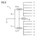
- Still another and even more refined staging can be achieved with an active staging control, where the group staging is actively regulated by a logic control piloting the control valves as a function of current measured values of e.g. emissions or hardware temperature or acoustic pulsations (flame stability), to ensure optimized fuel split over the load points.
- active staging control where the group staging is actively regulated by a logic control piloting the control valves as a function of current measured values of e.g. emissions or hardware temperature or acoustic pulsations (flame stability), to ensure optimized fuel split over the load points.
- fuel injection openings of different groups do not necessarily need to be neither identical nor different.
- the injection staging of the present invention provides means to always operate the burner such that optimum emission and flame stability is achieved by adapting the correct staging to different fuel injection openings.
- the combustor exit temperature profile is much better than in applications where (staged) groups of burners are operated within a moderate load range in two operating modes.
- a fuel injection staging proposed by the present invention all the burners are operating homogeneously, without firing temperature difference between burners as in the hot and cold groups of burners in the case, where the burners are grouped.
- the prior art burner grouping temperature profile variation will be even worse than in annular combustor systems, because there is no mixing between cans to even out the can to can temperature variations.
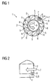
- FIG 1 illustrates a typical swirler 1 used as premix fuel injection system in a gas turbine engine.
- the swirler 1 comprises twelve swirler vanes 2 arranged on a swirler vane support 3.
- the swirler vanes 2 can be fixed to a burner head with their sides showing away from the swirler vane support 3.
- Neighbouring swirler vanes 2, burner head and swirler vane support 3 form swirler passages 4.
- fuel injection openings 5,6 are arranged in these swirler passages 4.
- compressor air 7 flows into the swirler passages 4.
- fuel 8 is injected through the fuel injection openings 5,6 into the streaming compressor air 7.
- the fuel/air mixture 9 then leaves the swirler passage 4 and streams through a central opening 10 of the swirler vane support 3 into a pre-chamber (not shown) and to the combustion zone, where it is burned.
- Figure 2 shows in more detail a perspective view of a swirler passage 4 with a swirler vane 2, compressor air 7 entering the swirler passage 4, and fuel 8 entering the swirler passage 4 through a fuel injection opening 5,6 and mixing with the compressor air 7 in the swirler passage 4.
- FIG. 3 a schematic diagram for fuel-air premixing arrangement 11 with constant fuel staging is shown. Constant fuel staging is the easiest way of staging the fuel supply.
- a control valve 12 controls the fuel flow in the main fuel supply line 13.
- the fuel flow to the fuel injection openings 5 of the first group is constantly and over the complete load range reduced by a valve element 14, an orifice 15, which is static and arranged in the common rail 16 of the fuel injection openings 5 of the first group.
- the common rail 17 of the second group of fuel injection openings 6 has no orifice. Thus the fuel flow in the common rail 17 of the second group is unimpeded.
- Figure 4 shows the chart for the constant fuel-air premixing arrangement 11 shown in Figure 3 .
- the fuel split is load-independent.
- Valve elements 14 allowing for dynamic control, control valves 12, are arranged in the common rails 16,17 of the first and second groups of fuel injection openings 5,6, respectively.
- the control valves 12 allow for an individual control of fuel mass flow in the common rails 16 and 17 of the respective groups of fuel injection openings 5 and 6.
- Figures 6 to 8 show charts for different preset fuel splits over load corresponding to the passive fuel staging concept shown in Figure 5.
- Figure 6 illustrates the case, where one of the two groups of fuel injection openings 5 is enriched at low load operation and both groups of fuel injection openings 5,6 are operated homogeneously at high load operation.
- Figure 7 illustrates the case, where one of the groups of fuel injection openings 5 is enriched over the complete load range.
- Figure 9 shows the corresponding schematic diagram.
- the fuel split between the groups of fuel injection openings 5,6 is not preset, but adjusted by a control logic 18, taking into account current measured values of e.g. emissions, dynamics and hardware temperature.
Landscapes
- Engineering & Computer Science (AREA)
- Chemical & Material Sciences (AREA)
- Combustion & Propulsion (AREA)
- Mechanical Engineering (AREA)
- General Engineering & Computer Science (AREA)
Priority Applications (5)
| Application Number | Priority Date | Filing Date | Title |
|---|---|---|---|
| EP07005408A EP1970629A1 (de) | 2007-03-15 | 2007-03-15 | Gestufte Brennstoffversorgung |
| PCT/EP2008/052875 WO2008110554A1 (en) | 2007-03-15 | 2008-03-11 | Burner fuel staging |
| EP08717622.8A EP2118570B1 (de) | 2007-03-15 | 2008-03-11 | Brennstoffversorgung für einen brenner |
| US12/531,351 US8484979B2 (en) | 2007-03-15 | 2008-03-11 | Burner fuel staging |
| CN200880008389.7A CN101636619B (zh) | 2007-03-15 | 2008-03-11 | 燃料-空气预混合布置结构、燃烧器及操作燃烧器的方法 |
Applications Claiming Priority (1)
| Application Number | Priority Date | Filing Date | Title |
|---|---|---|---|
| EP07005408A EP1970629A1 (de) | 2007-03-15 | 2007-03-15 | Gestufte Brennstoffversorgung |
Publications (1)
| Publication Number | Publication Date |
|---|---|
| EP1970629A1 true EP1970629A1 (de) | 2008-09-17 |
Family
ID=38520741
Family Applications (2)
| Application Number | Title | Priority Date | Filing Date |
|---|---|---|---|
| EP07005408A Withdrawn EP1970629A1 (de) | 2007-03-15 | 2007-03-15 | Gestufte Brennstoffversorgung |
| EP08717622.8A Not-in-force EP2118570B1 (de) | 2007-03-15 | 2008-03-11 | Brennstoffversorgung für einen brenner |
Family Applications After (1)
| Application Number | Title | Priority Date | Filing Date |
|---|---|---|---|
| EP08717622.8A Not-in-force EP2118570B1 (de) | 2007-03-15 | 2008-03-11 | Brennstoffversorgung für einen brenner |
Country Status (4)
| Country | Link |
|---|---|
| US (1) | US8484979B2 (de) |
| EP (2) | EP1970629A1 (de) |
| CN (1) | CN101636619B (de) |
| WO (1) | WO2008110554A1 (de) |
Families Citing this family (9)
| Publication number | Priority date | Publication date | Assignee | Title |
|---|---|---|---|---|
| DE102009054669A1 (de) * | 2009-12-15 | 2011-06-16 | Man Diesel & Turbo Se | Brenner für eine Turbine |
| JP4841679B2 (ja) * | 2010-04-15 | 2011-12-21 | 川崎重工業株式会社 | ガスタービンの制御装置 |
| US8468822B1 (en) * | 2010-12-07 | 2013-06-25 | Rix E. Evans | Charge preparation system for internal combustion engines |
| US9303562B2 (en) * | 2013-01-15 | 2016-04-05 | General Electric Company | Methods and systems for operating gas turbine engines |
| CN104696988A (zh) * | 2013-12-10 | 2015-06-10 | 中航商用航空发动机有限责任公司 | 燃气轮机的燃烧室及燃烧室的操作方法 |
| CN109854387A (zh) * | 2019-03-21 | 2019-06-07 | 贵州黎阳天翔科技有限公司 | 一种小型涡喷柴油发动机分段供油装置和分段燃烧方法 |
| US11174792B2 (en) | 2019-05-21 | 2021-11-16 | General Electric Company | System and method for high frequency acoustic dampers with baffles |
| US11156164B2 (en) | 2019-05-21 | 2021-10-26 | General Electric Company | System and method for high frequency accoustic dampers with caps |
| CN110454785B (zh) * | 2019-08-16 | 2021-03-12 | 乔永 | 一种低氮燃烧器 |
Citations (5)
| Publication number | Priority date | Publication date | Assignee | Title |
|---|---|---|---|---|
| EP0399336A1 (de) * | 1989-05-24 | 1990-11-28 | Hitachi, Ltd. | Brennkammer und ihre Arbeitsweise |
| US5311742A (en) * | 1991-11-29 | 1994-05-17 | Kabushiki Kaisha Toshiba | Gas turbine combustor with nozzle pressure ratio control |
| US5319931A (en) * | 1992-12-30 | 1994-06-14 | General Electric Company | Fuel trim method for a multiple chamber gas turbine combustion system |
| US20060257807A1 (en) * | 2002-12-23 | 2006-11-16 | Robert Hicks | Combustion device |
| JP2006336995A (ja) * | 2005-06-06 | 2006-12-14 | Mitsubishi Heavy Ind Ltd | ガスタービンの燃焼器 |
Family Cites Families (17)
| Publication number | Priority date | Publication date | Assignee | Title |
|---|---|---|---|---|
| US4027473A (en) * | 1976-03-05 | 1977-06-07 | United Technologies Corporation | Fuel distribution valve |
| US5036657A (en) * | 1987-06-25 | 1991-08-06 | General Electric Company | Dual manifold fuel system |
| US4817389A (en) * | 1987-09-24 | 1989-04-04 | United Technologies Corporation | Fuel injection system |
| US5099644A (en) | 1990-04-04 | 1992-03-31 | General Electric Company | Lean staged combustion assembly |
| US5235814A (en) * | 1991-08-01 | 1993-08-17 | General Electric Company | Flashback resistant fuel staged premixed combustor |
| EP0592717B1 (de) | 1992-10-16 | 1998-02-25 | Asea Brown Boveri Ag | Gasbetriebener Vormischbrenner |
| GB2284884B (en) * | 1993-12-16 | 1997-12-10 | Rolls Royce Plc | A gas turbine engine combustion chamber |
| JP2950720B2 (ja) * | 1994-02-24 | 1999-09-20 | 株式会社東芝 | ガスタービン燃焼装置およびその燃焼制御方法 |
| GB2319078B (en) * | 1996-11-08 | 1999-11-03 | Europ Gas Turbines Ltd | Combustor arrangement |
| GB2333832A (en) * | 1998-01-31 | 1999-08-04 | Europ Gas Turbines Ltd | Multi-fuel gas turbine engine combustor |
| EP0974789B1 (de) | 1998-07-22 | 2004-05-06 | ALSTOM Technology Ltd | Verfahren zum Betrieb einer Gasturbinenbrennkammer mit flüssigem Brennstoff |
| DE59810344D1 (de) | 1998-07-27 | 2004-01-15 | Alstom Switzerland Ltd | Verfahren zum Betrieb einer Gasturbinenbrennkammer mit gasförmigem Brennstoff |
| SE521293C2 (sv) * | 2001-02-06 | 2003-10-21 | Volvo Aero Corp | Förfarande och anordning för tillförsel av bränsle till en brännkammare |
| DE60217768T2 (de) * | 2001-07-18 | 2007-11-15 | Rolls-Royce Plc | Kraftstofffördervorrichtung |
| US7836699B2 (en) * | 2005-12-20 | 2010-11-23 | United Technologies Corporation | Combustor nozzle |
| US7665309B2 (en) * | 2007-09-14 | 2010-02-23 | Siemens Energy, Inc. | Secondary fuel delivery system |
| US8122725B2 (en) * | 2007-11-01 | 2012-02-28 | General Electric Company | Methods and systems for operating gas turbine engines |
-
2007
- 2007-03-15 EP EP07005408A patent/EP1970629A1/de not_active Withdrawn
-
2008
- 2008-03-11 WO PCT/EP2008/052875 patent/WO2008110554A1/en active Application Filing
- 2008-03-11 EP EP08717622.8A patent/EP2118570B1/de not_active Not-in-force
- 2008-03-11 US US12/531,351 patent/US8484979B2/en not_active Expired - Fee Related
- 2008-03-11 CN CN200880008389.7A patent/CN101636619B/zh not_active Expired - Fee Related
Patent Citations (5)
| Publication number | Priority date | Publication date | Assignee | Title |
|---|---|---|---|---|
| EP0399336A1 (de) * | 1989-05-24 | 1990-11-28 | Hitachi, Ltd. | Brennkammer und ihre Arbeitsweise |
| US5311742A (en) * | 1991-11-29 | 1994-05-17 | Kabushiki Kaisha Toshiba | Gas turbine combustor with nozzle pressure ratio control |
| US5319931A (en) * | 1992-12-30 | 1994-06-14 | General Electric Company | Fuel trim method for a multiple chamber gas turbine combustion system |
| US20060257807A1 (en) * | 2002-12-23 | 2006-11-16 | Robert Hicks | Combustion device |
| JP2006336995A (ja) * | 2005-06-06 | 2006-12-14 | Mitsubishi Heavy Ind Ltd | ガスタービンの燃焼器 |
Also Published As
| Publication number | Publication date |
|---|---|
| US8484979B2 (en) | 2013-07-16 |
| CN101636619A (zh) | 2010-01-27 |
| EP2118570B1 (de) | 2013-09-18 |
| WO2008110554A1 (en) | 2008-09-18 |
| EP2118570A1 (de) | 2009-11-18 |
| CN101636619B (zh) | 2013-02-06 |
| US20100064692A1 (en) | 2010-03-18 |
Similar Documents
| Publication | Publication Date | Title |
|---|---|---|
| EP2118570B1 (de) | Brennstoffversorgung für einen brenner | |
| US5640851A (en) | Gas turbine engine combustion chamber | |
| EP1426689B1 (de) | Gasturbinenbrennkammer mit Vormischbrennern, die eine verschiedene Geometrie aufweisen | |
| EP2613082B1 (de) | System und Verfahren für die Zufuhr eines Arbeitsmittels in einer Brennkammer | |
| US6016658A (en) | Low emissions combustion system for a gas turbine engine | |
| US6684642B2 (en) | Gas turbine engine having a multi-stage multi-plane combustion system | |
| US8850821B2 (en) | System for fuel injection in a fuel nozzle | |
| EP1960650B1 (de) | Verbesserte luftstromverteilung zu einer gasturbinen-brennkammer | |
| US9671112B2 (en) | Air diffuser for a head end of a combustor | |
| RU2506499C2 (ru) | Топливные форсунки газовой турбины с противоположными направлениями завихрения | |
| US8677753B2 (en) | System for supplying a working fluid to a combustor | |
| US7878799B2 (en) | Multiple burner arrangement for operating a combustion chamber, and method for operating the multiple burner arrangement | |
| US20140090396A1 (en) | Combustor with radially staged premixed pilot for improved | |
| US20140190170A1 (en) | Fuel injector for supplying fuel to a combustor | |
| US20030106321A1 (en) | Lean premix burner for a gas turbine and operating method for a lean premix burner | |
| US20180045414A1 (en) | Swirler, burner and combustor for a gas turbine engine | |
| EP2615372A2 (de) | System und Verfahren für die Zufuhr eines Arbeitsfluids zu einem Brenner | |
| EP2340398B1 (de) | Hauptdrallvorrichtungen mit abwechselnder drallrichtung in magervorgemischten gasturbinenbrennkammern | |
| US8726671B2 (en) | Operation of a combustor apparatus in a gas turbine engine |
Legal Events
| Date | Code | Title | Description |
|---|---|---|---|
| PUAI | Public reference made under article 153(3) epc to a published international application that has entered the european phase |
Free format text: ORIGINAL CODE: 0009012 |
|
| AK | Designated contracting states |
Kind code of ref document: A1 Designated state(s): AT BE BG CH CY CZ DE DK EE ES FI FR GB GR HU IE IS IT LI LT LU LV MC MT NL PL PT RO SE SI SK TR |
|
| AX | Request for extension of the european patent |
Extension state: AL BA HR MK RS |
|
| AKX | Designation fees paid | ||
| REG | Reference to a national code |
Ref country code: DE Ref legal event code: 8566 |
|
| STAA | Information on the status of an ep patent application or granted ep patent |
Free format text: STATUS: THE APPLICATION IS DEEMED TO BE WITHDRAWN |
|
| 18D | Application deemed to be withdrawn |
Effective date: 20090318 |