EP1970593A1 - Hydraulic shock absorber - Google Patents
Hydraulic shock absorber Download PDFInfo
- Publication number
- EP1970593A1 EP1970593A1 EP08004623A EP08004623A EP1970593A1 EP 1970593 A1 EP1970593 A1 EP 1970593A1 EP 08004623 A EP08004623 A EP 08004623A EP 08004623 A EP08004623 A EP 08004623A EP 1970593 A1 EP1970593 A1 EP 1970593A1
- Authority
- EP
- European Patent Office
- Prior art keywords
- oil chamber
- oil
- shock absorber
- piston
- piston rod
- Prior art date
- Legal status (The legal status is an assumption and is not a legal conclusion. Google has not performed a legal analysis and makes no representation as to the accuracy of the status listed.)
- Granted
Links
Images


Classifications
-
- F—MECHANICAL ENGINEERING; LIGHTING; HEATING; WEAPONS; BLASTING
- F16—ENGINEERING ELEMENTS AND UNITS; GENERAL MEASURES FOR PRODUCING AND MAINTAINING EFFECTIVE FUNCTIONING OF MACHINES OR INSTALLATIONS; THERMAL INSULATION IN GENERAL
- F16F—SPRINGS; SHOCK-ABSORBERS; MEANS FOR DAMPING VIBRATION
- F16F9/00—Springs, vibration-dampers, shock-absorbers, or similarly-constructed movement-dampers using a fluid or the equivalent as damping medium
- F16F9/32—Details
- F16F9/43—Filling or drainage arrangements, e.g. for supply of gas
- F16F9/435—Filling or drainage arrangements, e.g. for supply of gas via opening in cylinder wall
-
- F—MECHANICAL ENGINEERING; LIGHTING; HEATING; WEAPONS; BLASTING
- F16—ENGINEERING ELEMENTS AND UNITS; GENERAL MEASURES FOR PRODUCING AND MAINTAINING EFFECTIVE FUNCTIONING OF MACHINES OR INSTALLATIONS; THERMAL INSULATION IN GENERAL
- F16F—SPRINGS; SHOCK-ABSORBERS; MEANS FOR DAMPING VIBRATION
- F16F9/00—Springs, vibration-dampers, shock-absorbers, or similarly-constructed movement-dampers using a fluid or the equivalent as damping medium
- F16F9/06—Springs, vibration-dampers, shock-absorbers, or similarly-constructed movement-dampers using a fluid or the equivalent as damping medium using both gas and liquid
- F16F9/061—Mono-tubular units
-
- F—MECHANICAL ENGINEERING; LIGHTING; HEATING; WEAPONS; BLASTING
- F16—ENGINEERING ELEMENTS AND UNITS; GENERAL MEASURES FOR PRODUCING AND MAINTAINING EFFECTIVE FUNCTIONING OF MACHINES OR INSTALLATIONS; THERMAL INSULATION IN GENERAL
- F16F—SPRINGS; SHOCK-ABSORBERS; MEANS FOR DAMPING VIBRATION
- F16F9/00—Springs, vibration-dampers, shock-absorbers, or similarly-constructed movement-dampers using a fluid or the equivalent as damping medium
- F16F9/10—Springs, vibration-dampers, shock-absorbers, or similarly-constructed movement-dampers using a fluid or the equivalent as damping medium using liquid only; using a fluid of which the nature is immaterial
- F16F9/14—Devices with one or more members, e.g. pistons, vanes, moving to and fro in chambers and using throttling effect
- F16F9/16—Devices with one or more members, e.g. pistons, vanes, moving to and fro in chambers and using throttling effect involving only straight-line movement of the effective parts
- F16F9/18—Devices with one or more members, e.g. pistons, vanes, moving to and fro in chambers and using throttling effect involving only straight-line movement of the effective parts with a closed cylinder and a piston separating two or more working spaces therein
- F16F9/20—Devices with one or more members, e.g. pistons, vanes, moving to and fro in chambers and using throttling effect involving only straight-line movement of the effective parts with a closed cylinder and a piston separating two or more working spaces therein with the piston-rod extending through both ends of the cylinder, e.g. constant-volume dampers
Definitions
- This invention relates to a hydraulic shock absorber suspended between a wheel side which is one part of a shock-absorbed body and a vehicle-body side which is another part of the shock-absorbed body, for absorbing an impact force applied to the shock-absorbed body in case that the shock-absorbed body is, for example, a suspension system of an automobile.
- the hydraulic shock absorber is a single-rod type including: a cylinder tube connected to one part of a shock-absorbed body which is a suspension system of an automobile; a free piston fitted in the cylinder tube slidably in the axial direction for dividing the cylinder tube into an oil chamber filled with hydraulic oil and a gas chamber filled with high-pressure gas; a piston fitted in the oil chamber slidably in the axial direction for dividing the oil chamber into a first and second oil chambers; a piston rod projecting from the piston and extending to the outside of the cylinder tube through the first oil chamber located opposite to the gas chamber with its extension end being connected to another part of the shock-absorbed body; and a damping force generator for generating a damping force with the hydraulic oil flowing between the first and second oil chambers.
- the gas chamber and the gas filled in the gas chamber function as an oil chamber pressurizing means for normally pressurizing the hydraulic oil in the first and second oil chambers.
- the oil chamber pressurizing means With the oil chamber pressurizing means, occurrence of such a problem that bubbles are generated in the hydraulic oil due to the negative pressure in the first and second oil chambers when the shock absorber is operated or the volume of the hydraulic oil varies with temperature change can be prevented. Thereby, damping characteristics of the shock absorber can be maintained better.
- a shock absorber adapted to a suspension system of an automobile is generally configured as follows. That is, the cylinder tube is connected to the wheel side and the extension end of the piston rod is connected to the vehicle-body side via a rubber mount. A suspension spring is provided between the cylinder tube and the vehicle-body side for urging the shock absorber for its extension movement.
- each of axial end surfaces of the piston is a pressure receiving surface which receives pressure of the hydraulic oil.
- the pressure receiving area of one pressure receiving surface is larger than that of another pressure receiving surface from which the piston rod projects by the sectional area of the piston rod. Therefore, as described above, when the hydraulic oil is normally pressurized by pressure of the gas of the oil chamber pressurizing means, the piston is urged in an extending direction of the piston rod by an urging force (R), which is a pressurized reaction force generated by the pressure of the hydraulic oil based on the oil chamber pressurizing means and the difference of the pressure receiving area described above.
- R urging force
- the urging force (R) urges the rubber mount upward. Therefore, for example, when the automobile is in a stationary state, an initial elastic deformation appears on the rubber mount in the upward pulling direction caused by the urging force (R).
- the rubber mount makes elastic deformation with elasticity uniform as much as possible (desired elastic deformation) in each type of operation.
- the rubber mount is designed to obtain such rubber mount characteristics that when an upward load is applied, the rubber mount softly makes elastic deformation in the pulling direction, while when a downward load is provided, the rubber mount stiffly makes elastic deformation in the compression direction.
- the rubber mount with the "desired elastic deformation” would be obtained in each of compression or extension movement of the shock absorber described above under the condition that the initial elastic deformation appears on the rubber mount caused by the urging force (R) in the stationary state of the automobile.
- the hydraulic shock absorber is a double-rod type including: a cylinder tube connected to one part of a shock-absorbed body; a piston fitted in the cylinder tube slidably in an axial direction thereof for dividing the cylinder tube into a first and second oil chambers; a main piston rod extending from the piston to the outside of the first oil chamber through the first oil chamber with its extension end being connected to another part of the shock-absorbed body; a sub piston rod extending from the piston to the outside of the second oil chamber through the second oil chamber; an oil chamber pressurizing means for normally pressurizing hydraulic oil in the first and second oil chambers; and a damping force generator for generating a damping force with the hydraulic oil flowing between the first and second oil chambers.
- Patent Document 1 JP-A-2004-232845
- Patent Document 2 JP-A-Hei11-165521
- each piston rod extends from each axial end surface to the outside of each cylinder tube. Accordingly, the pressure receiving area of each pressure receiving surface of the piston becomes generally equal. Therefore, though the oil chamber pressurizing means normally pressurizes the hydraulic oil, the urging force (R), which is a pressurized reaction force of the gas is not generated. As a result, the piston is not urged to either of axial directions together with each piston rod. That is, the double-rod type shock absorber does not have characteristics that make the extension movement in the free state.
- the rubber mount first starts to deform elastically from the free state, and the elastic deformation proceeds to reach the initial elastic deformation state and then the rubber mount exhibits damping characteristics similar to those of the single-rod type shock absorber for the first time.
- the double-rod type shock absorber is adapted instead of the single-rod type shock absorber with the rubber mount unchanged, a time lag occurs in generating a damping force, which makes the rubber mount characteristics unsuitable. This may cause deterioration of the riding comfort of the automobile and therefore is not preferable.
- the present invention has been made in view of the foregoing situation and the object of the invention is to provide a hydraulic shock absorber which easily adjusts the urging force for urging a shock absorber so that the shock absorber normally makes an extension movement in the free state and thereby improves adaptation flexibility of the shock absorber in such a manner that the shock absorber can be easily adapted to any rubber mounts with various rubber mount characteristics such as, for example, a rubber mount that has rubber mount characteristics suitable for a single-rod type shock absorber in a suspension system on an automobile.
- a hydraulic shock absorber comprising: a cylinder tube connected to one part of a shock-absorbed body; a piston fitted into the cylinder tube slidably in an axial direction thereof for dividing the cylinder tube into first and second oil chambers; a main piston rod extending from the piston to the outside of the first oil chamber through the first oil chamber, the main piston rod having an extension end being connected to another part of the shock-absorbed body; an oil chamber pressurizing means for pressurizing an hydraulic oil in the first and second oil chambers; a sub piston rod extending from the piston to the outside of the second oil chamber through the second oil chamber; and a sealed space for accommodating an extension end of the sub piston rod, wherein a gas having a pressure larger than atmospheric pressure and smaller than a pressure applied on the hydraulic oil by the oil chamber pressurizing means is provided in the sealed space.
- the hydraulic shock absorber further comprises a damping force generator for generating a damping force with the hydraulic oil flowing between the first and second oil chambers.
- the hydraulic shock absorber further comprises an injection valve for achieving injection or discharge of the gas in or from the sealed space.
- the cylinder tube includes: a tube body extending in an axial direction thereof; a fixed rod guide fixed to the tube body in such a manner that an end opening in the first oil chamber positioned opposite to the piston is closed, the main piston rod slidably passing through the fixed rod guide; and a movable rod guide slidably fitted in the tube body in an axial direction thereof in such a manner that an end opening in the second oil chamber positioned opposite to the piston is closed, the sub piston rod slidably passing through the movable rod guide, and wherein a solid spring as the oil chamber pressurizing means for normally urging the movable rod guide toward the first and second oil chambers side is provided in the sealed space.
- the cylinder tube includes: a tube body extending in an axial direction thereof; a fixed rod guide fixed to the tube body in such a manner that an end opening in the first oil chamber positioned opposite to the piston is closed, and main piston rod slidably passing through the fixed rod guide; and another fixed rod guide fixed to the tube body in such a manner that an end opening in the second oil chamber positioned opposite to the piston is closed, the sub piston rod slidably passing through the other fixed rod guide, and wherein an accumulator as the oil chamber pressurizing means is provided for normally pressurizing the hydraulic oil in the first and second oil chambers by a pressure of another gas.
- a hydraulic shock absorber includes: a cylinder tube connected to one part of a shock-absorbed body; a piston fitted in the cylinder tube slidably in an axial direction thereof for dividing the cylinder tube into a first and second oil chambers; a main piston rod extending from the piston to the outside of the first oil chamber through the first oil chamber with its extension end being connected to another part of the shock-absorbed body; a sub piston rod extending from the piston to the outside of the second oil chamber through the second oil chamber; an oil chamber pressurizing means for normally pressurizing hydraulic oil in the first and second oil chambers; and a damping force generator for generating a damping force with the hydraulic oil flowing between the first and second oil chambers.
- a sealed space for containing an extension end of the sub piston rod is defined. Gas having a pressure larger than atmospheric pressure and smaller than a pressure applied on the hydraulic oil by the oil chamber pressurizing means is filled in the sealed space.
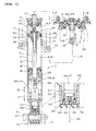
- reference numeral 1 denotes a double-rod type hydraulic shock absorber.
- the shock absorber 1 is suspended between one part 3 and another part 4 of a shock-absorbed body 2.
- the shock-absorbed body 2 is, for example, a suspension system of a vehicle such as an automobile and a motorcycle.
- the one part 3 is a wheel side and the other part 4 is a vehicle-body side.
- the shock absorber 1 and the other part 4 are connected with each other by a rubber mount 5 interposed therebetween.
- the shock absorber 1 includes: a cylinder tube 7 connected to the one part 3 of the shock-absorbed body 2 with its axis 6 extending vertically; a piston 11 fitted in one end (upper end) of the cylinder tube 7 slidably in an axial direction thereof for dividing the cylinder tube 7 into a first and second oil chambers 9, 10 filled with hydraulic oil 8; a main piston rod 12 extending from the piston 11 to the outside of the first oil chamber 9 through the first oil chamber 9 with its extension end 12a being connected to the other part 4 of the shock-absorbed body 2; a sub piston rod 13 extending from the piston 11 to the outside of the second oil chamber 10 through the second oil chamber 10; a fastener 14 for detachably fixing a proximal side of the sub piston rod 13 to the piston 11; and an oil chamber pressurizing means 15 for normally pressurizing the hydraulic oil 8 in the first and second oil chambers 9, 10.
- the main and sub piston rods 12, 13 have a generally same diameter. Therefore, when each axial end surface of the piston 11 receives pressure from the hydraulic oil 8 in the first and second oil chambers 9, 10, the pressure receiving area faced to the hydraulic oil 8 of each end surface of the piston 11 becomes generally equal.
- the cylinder tube 7 includes: a cylindrical tube body 16 extending in an axial direction thereof; a fixed rod guide 17 fixed to the tube body 16 in such a manner that an end opening in the first oil chamber 9 positioned opposite to the piston 11 is closed, the main piston rod 12 slidably passing through the fixed rod guide 17; and a movable rod guide 18 slidably fitted in the tube body 16 in such a manner that an end opening in the second oil chamber 10 positioned opposite to the piston 11 is closed, the sub piston rod 13 slidably passing through the movable rod guide 18.
- the lower end of the cylinder tube 7 is pivotally supported via a connector 21 on the one part 3 of the shock-absorbed body 2.
- the connector 21 includes: a connector body 23 detachably engaged with a male thread 22 formed at the lower end of the tube body 16; a known absorbing body 26 pressed into a round hole formed in the connector body 23; and a pivot shaft 27 inserted by the absorbing body 26 for enabling the one part 3 of the shock-absorbed body 2 and the cylinder tube 7 to pivotally support each other.
- the extension end 12a of the main piston rod 12 is connected to the other part 4 of the shock-absorbed body 2 by a fastener 29 via the rubber mount 5.
- the rubber mount 5 has such rubber mount characteristics that when an upward load is applied to the rubber mount 5, the rubber mount 5 softly makes elastic deformation in the pulling direction, while when a downward load is applied, the rubber mount 5 stiffly makes elastic deformation in the compression direction.
- the shock absorber 1 can make an extension movement A and a compression movement B by the piston 11 sliding relative to the cylinder tube 7.
- a suspension spring 30 is interposed between the other part 4 of the shock-absorbed body 2 and the cylinder tube 7 to enable the shock absorber 1 to make the extension movement A.
- An extension side damping force generator 33 is provided for generating a damping force by flowing the hydraulic oil 8 from the first oil chamber 9 to the second oil chamber 10, when the shock absorber 1 makes the extension movement A.
- the extension side damping force generator 33 includes an extension side oil passage 34 formed in the piston 11 for communicating the first oil chamber 9 with the second oil chamber 10 and an extension side damping valve 35, which is a leaf valve, attached to the piston 11 to be opened or closed resiliently for closing the extension side oil passage 34 from the second oil chamber 10 side.
- a compression side damping force generator 37 for generating a damping force by flowing the hydraulic oil 8 from the second oil chamber 10 to the first oil chamber 9.
- the compression side damping force generator 37 includes: a compression side oil passage 38 formed in the piston 11 for communicating the first oil chamber 9 with the second oil chamber 10; and a compression side damping valve 39, which is a leaf valve, attached to the piston 11 to be opened or closed resiliently for closing the compression side oil passage 38 from the first oil chamber 9 side.
- the extension side damping force generator 33 and the compression side damping force generator 37 each include as a common component: another oil passage 40 formed between the piston rod 11 and the main piston rod 12 for communicating the first oil chamber 9 with the second oil chamber 10; an adjustment valve 41, which is a needle valve, fitted in a hole formed on the axis 6 of the main piston rod 12 for adjusting an opening degree of a part of the other oil passage 40 in the main piston rod 12; an engaging operation part 42 in a plug shape screwed on the extension end 12a of the piston rod 12 and to be engaged with a tool; and an operation shaft 43 inserted in the hole formed on the axis 6 of the main piston rod 12.
- the opening degree of the other oil passage 40 can be adjusted by the adjustment valve 41 in conjunction with an operation by the tool on the engaging operation part 42 via the operation shaft 43.
- a sealed space 46 for containing an extension end 13a of the sub piston rod 13 is defined.
- Nitrogen gas 47 is filled, of which pressure (0.5 -0.8 Mpa) is larger than atmospheric pressure and smaller than a pressure (approximately 2 Mpa) applied on the hydraulic oil 8 by the oil chamber pressurizing means 15. Filling and pressure adjustment of the gas 47 are generally carried out in the assembling process of the shock absorber 1 on an assembly line of the shock absorber 1. However, the shock absorber 1 may be adjusted in its assembly form without disassembling components of the shock absorber 1 after assembling the shock absorber 1 as described below.
- the extension end 13a of the sub piston rod 13 is disposed inside the lower part of the cylinder tube 7.
- a lid 48 with a small diameter in a cylindrical shape is fixed to the lower end of the cylinder tube 7.
- a plug 49 is screwed in an opening of the lid 48 on the axis 6. Thereby, the opening of the lid 48 is controlled to be opened or closed.
- An O-ring 50 provides a seal between an inner surface of the opening of the lid 48 and the plug 49. Thereby, the sealed space 46 is defined inside the lower part of the cylinder tube 7.
- a through hole 53 is formed in the plug 49 on the axis 6.
- An injection valve 54 made of rubber block is secured from the sealed space 46 side for closing the through hole 53.
- the injection valve 54 allows for injection or discharge of the gas 47 in or from the sealed space 46.
- injection or discharge of the gas 47 for the sealed space 46 is performed with a needle-shaped injector 55 which can be inserted in the injection valve 54.
- the injection or discharge of the gas 47 is performed in the state that the cylinder tube 7 is separated from the connector 21.
- Pressure of the gas 47 at the injector 55 can be detected by a pressure gauge and thereby pressure of the gas 47 in the sealed space 46 can be adjusted to a desired pressure value.
- a solid spring 58 for normally urging the movable rod guide 18 toward the first and second oil chambers 9, 10 side and a cylindrical sliding member 59 interposed between the movable rod guide 18 and the solid spring 58 in the axial direction of the cylinder tube 7, through which the sub piston rod 13 extends are provided.
- the spring 58 is a coil spring made of metal or plastic positioned on the axis 6 and interposed between the lid 48 and the sliding member 59.
- the sliding member 59 is fitted with no play in the tube body 16 to be slidable in the axial direction.
- the movable rod guide 18 side end surface of the sliding member 59 is formed to cross the axis 6 perpendicularly and is in surface contact with an axial end surface of the movable rod guide 18.
- the shock absorber 1 makes the extension movement A by an urging force of the suspension spring 30.
- the hydraulic oil 8 in the first oil chamber 9 flows to the second oil chamber 10 through the extension side oil passage 34 of the extension side damping force generator 33.
- the extension side damping valve 35 elastically deforms to open the valve with hydraulic pressure generated by the hydraulic oil 8 in the first oil chamber 9 exceeding an elastic urging force of the extension side damping valve 35.
- the hydraulic oil 8 then flows with elastic resistance from the extension side damping valve 35 through the extension side oil passage 34 which is opened as described above. This flow generates the damping force which absorbs the impact force.
- the shock absorber 1 with the impact force makes the compression movement B against the urging force of the suspension spring 30.
- the hydraulic oil 8 in the second oil chamber 10 flows to the first oil chamber 9 through the compression side oil passage 38 of the compression side damping force generator 37.
- the compression side damping valve 39 elastically deforms to open the valve with hydraulic pressure generated by the hydraulic oil 8 in the second oil chamber 10 exceeding an elastic urging force of the compression side damping valve 39.
- the hydraulic oil 8 then flows with elastic resistance from the compression side damping valve 39 through the compression side oil passage 38 which is opened as described above. This flow generates the damping force which absorbs the impact force.
- the shock absorber 1 makes the extension movement A or the compression movement B as described above, the hydraulic oil 8 flows between the first and second oil chambers 9, 10 through the other oil passage 40. These flows also generate the damping force which absorbs the impact force.
- the damping force generated by the extension movement A or the compression movement B of the shock absorber 1 can be adjusted by adjusting the opening degree of the other oil passage 40 with the adjustment valve 41 by the operation of the engaging operation part 42.
- the hydraulic oil 8 in the first and second oil chambers 9, 10 is normally pressurized by the urging force of the spring 58 via the movable rod guide 18.
- occurrence of such a problem that bubbles are generated in the hydraulic oil 8 due to the negative pressure in the first and second oil chambers 9, 10 when the shock absorber 1 is operated or the volume of the hydraulic oil 8 varies with temperature change can be prevented.
- damping characteristics of the shock absorber 1 can be maintained better.
- the sealed space 46 for containing the extension end 13a of the sub piston rod 13 is defined and the gas 47 having a pressure larger than atmospheric pressure and smaller than the pressure applied on the hydraulic oil 8 by the oil chamber pressurizing means 15, is filled in the sealed space 46.
- an urging force (R') is provided to the extension end 13a of the sub piston rod 13 contained in the sealed space 46 based on values of the cross sectional area S of the sub piston rod 13 and the pressure of the gas 47. Accordingly, for example, when the diameters of the main piston rod 12 and the sub piston rod 13 are set larger in order to change capacity and strength of the shock absorber 1, the urging force (R') can be adjusted to a relatively small value by decreasing the pressure of the gas 47 on the other hand. That is, according to the above embodiment, the urging force (R') for urging the shock absorber 1 to normally make the extension movement in its free state can be easily adjusted only by adjusting the pressure of the gas 47 in the sealed space 46. Thereby, adaptation flexibility of the shock absorber 1 can be advantageously improved.
- the pressure of the gas 47 filled in the sealed space 46 is smaller than the pressure applied on the hydraulic oil 8 by the oil chamber pressurizing means 15. Accordingly, fine adjustments of the urging force (R') can be easily achieved by varying the pressure of the gas 47.
- the urging force (R') urges the rubber mount 5 upward. Therefore, for example, when the automobile is in a stationary state, an initial elastic deformation appears on the rubber mount 5 in the upward pulling direction caused by the urging force (R').
- the shock absorber 1 makes the extension movement A or the compression movement B under the conditions described above.
- the urging force (R') generates the initial elastic deformation on the rubber mount 5.
- the spring reaction force of the rubber mount 5 rapidly responds to the compression movement B and the piston 11 responsively slides in the cylinder tube 7.
- the hydraulic oil 8 responsively flows between the first and second oil chambers 9, 10 through the damping force generators 33, 37. Thereby, this flow generates the damping force which absorbs the impact force.
- This function is similar to that in case that the single-rod type shock absorber is adapted.
- the rubber mount 5 with all types of rubber mount characteristics such as, for example, a rubber mount 5 that has rubber mount characteristics suitable for a single-rod type shock absorber 1 in a suspension system on an automobile can be easily adapted to the shock absorber 1.
- the injection valve 54 is provided for achieving injection or discharge of the gas 47 in or from the sealed space 46.
- the cylinder tube 7 includes: the tube body 16 extending in an axial direction thereof; the fixed rod guide 17 fixed to the tube body 16 in such a manner that an end opening in the first oil chamber 9 positioned opposite to the piston 11 is closed, the main piston rod 12 slidably passing through the fixed rod guide 17; and a movable rod guide 18 slidably fitted in the tube body 16 in an axial direction thereof in such a manner that an end opening in the second oil chamber 10 positioned opposite to the piston 11 is closed, the sub piston rod 13 slidably passing through the movable rod guide 18.
- the solid spring 58 for normally urging the movable rod guide 18 toward the first and second oil chambers 9, 10 side is provided in the sealed space 46.
- the shock absorber 1 can be constructed simply by using the solid spring 58, which has a simple construction and has no possibility of fluid leak, as the oil chamber pressurizing means 15.
- the spring 58 is disposed in the sealed space 46.
- the sealed space 46 for containing the gas 47 is utilized for locating the spring 58, thereby making the shock absorber 1 compact.
- the shock absorber 1 may constructed to be upside down and may be disposed horizontally or aslant.
- the damping force generator may be a fixed orifice or the like provided outside the cylinder tube 7.
- the sealed space 46 may be defined separately from the cylinder tube 7. injection or discharge of the gas 47 in or from the sealed space 46 may be performed only on an assembly line and may be inhibited for the user to perform by omitting to provide the injection valve 54 for example.
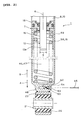
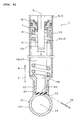
- FIGs. 2 to 5 illustrate second to fifth embodiments of the present teaching.
- the components, functions and effects of these embodiments are similar in many respects to those of the first embodiment above. Therefore, those parts corresponding to the components in the first embodiment are identified with the same reference numerals and symbols in the drawings and their description is not repeated, and their differences are mainly described below.
- the structures of the parts of the embodiments may be combined in various ways in the light of the objects and effects of the present teaching.
- the lid 48 is fixed to the lower end of the cylinder tube 7 in order to close the opening thereof.
- a connector body 23 of the connector 21 is fixed to the lid 48.
- a gas passage 62 is formed in the lid 48 for communicating the outside and inside of the sealed space 46.
- the injection valve 54 is pressed into the gas passage 62 at the outside end of the sealed space 46 and a plug 63 formed with the through hole 53 is detachably screwed in the end opening of the gas passage 62.
- a hole axis of the through hole 53 is generally perpendicular to the axis 6.
- a hole is formed on a lower wall of the cylinder tube 7 which defines the sealed space 46.
- a socket 64 is fixed on the lower sidewall to be communicated with the hole.
- the injection valve 54 is pressed into the socket 64 and a plug 49 formed with the through hole 53 is screwed to the socket 64.
- a hole axis of the through hole 53 is generally perpendicular to the axis 6.
- the through hole 53 is formed in the connector body 23 and the injection valve 54 is sandwiched between the lid 48 and the connector body 23 of the connector 21.
- the injection valve 54 provides a seal between the lid 48 and the connector body 23.
- a hole axis of the through hole 53 extends obliquely upward toward the injection valve 54.
- tube body 16 is separated into an upper and lower tube. Separated ends thereof are engaged with each other and fixed by a fastener 65.
- the movable rod guide 18 in the first embodiment is replaced with another fixed rod guide 17' which instead is fixed on the tube body 16.
- An accumulator 67 is provided for normally pressurizing the hydraulic oil 8 in the first and second oil chambers 9, 10 with another gas 66 as the oil chamber pressurizing means 15.
- the accumulator 67 is fixed to the cylinder tube 7 by a fastener 68.
- the accumulator 67 includes another cylinder tube 69 provided outside the cylinder tube 7 and a free piston 72 slidably fitted in the cylinder tube 69 in an axial direction thereof for dividing the cylinder tube 69 into an oil chamber 70 and a gas chamber 71.
- the oil chamber 70 is filled with the hydraulic oil 8 and communicated with the second oil chamber 10 through an oil passage 74 formed in a bolt of the fastener 68.
- the other gas 66 which is high-pressure (approximately 2 Mpa) nitrogen gas, is contained in the gas chamber 71 and pressurizes the hydraulic oil 8 in the first and second oil chambers 9, 10 via the free piston 72.
- the pressure which normally pressurizes the hydraulic oil 8 can be easily adjusted by adjusting the pressure of the other gas 66 in the accumulator 67, thereby easily obtaining the suitable shock absorber 1.
- a hydraulic shock absorber including: a cylinder tube 7 connected to one part 3 of a shock-absorbed body 2; a piston 11 fitted in the cylinder tube 7 slidably in an axial direction thereof for dividing the cylinder tube 7 into a first and second oil chambers 9, 10; a main piston rod 12 extending from the piston 11 to the outside of the first oil chamber 9 through the first oil chamber 9, the main piston rod 12 having an extension end 12a being connected to another part 4 of the shock-absorbed body 2; a sub piston rod 13 extending from the piston 11 to the outside of the second oil chamber 10 through the second oil chamber 10; an oil chamber pressurizing means 15 for normally pressurizing a hydraulic oil 8 in the first and second oil chambers 9, 10; and damping force generators 33, 37 for generating a damping force with the hydraulic oil 8 flowing between the first and second oil chambers 9, 10, in which a sealed space 46 for containing an extension end 13a of a sub piston rod 13
- an hydraulic shock absorber in which an injection valve 54 is provided for achieving injection or discharge of the gas 47 in or from the sealed space 46.
- a hydraulic shock absorber in which the cylinder tube 7 includes: a tube body 16 extending in an axial direction thereof; a fixed rod guide 17 fixed to the tube body 16 in such a manner that an end opening in the first oil chamber 9 positioned opposite to the piston 11 is closed, the main piston rod 12 slidably passing through the fixed rod guide 17; and a movable rod guide 18 slidably fitted in the tube body 16 in an axial direction thereof in such a manner that an end opening in the second oil chamber 10 positioned opposite to the piston 11 is closed, the sub piston rod 13 slidably passing through the movable rod guide 18, and in which a solid spring 58 as the oil chamber pressurizing means 15 for normally urging the movable rod guide 18 toward the first and second oil chambers 9, 10 side is provided in the sealed space 46.
- a hydraulic shock absorber in which the cylinder tube 7 includes: a tube body 16 extending in an axial direction thereof; a fixed rod guide 17 fixed to the tube body 16 in such a manner that an end opening in the first oil chamber 9 positioned opposite to the piston 11 is closed, the main piston rod 12 slidably passing through the fixed rod guide 17; and another fixed rod guide 17' fixed to the tube body 16 in such a manner that an end opening in the second oil chamber 10 positioned opposite to the piston 11 is closed, the sub piston rod 13 slidably passing through the other fixed rod guide 17', and in which an accumulator 67 as the oil chamber pressurizing means 15 is provided for normally pressurizing the hydraulic oil 8 in the first and second oil chambers 9, 10 by a pressure of another gas 66.
- the hydraulic shock absorber includes: a cylinder tube connected to one part of a shock-absorbed body; a piston fitted in the cylinder tube slidably in an axial direction thereof for dividing the cylinder tube into a first and second oil chambers; a main piston rod extending from the piston to the outside of the first oil chamber through the first oil chamber with its extension end being connected to another part of the shock-absorbed body; a sub piston rod extending from the piston to the outside of the second oil chamber through the second oil chamber; an oil chamber pressurizing means for normally pressurizing hydraulic oil in the first and second oil chambers; and a damping force generator for generating a damping force with the hydraulic oil flowing between the first and second oil chambers, in which a sealed space for containing an extension end of the sub piston rod is defined and gas having a pressure lager than atmospheric pressure and smaller than a pressure applied on the hydraulic oil by the oil chamber pressurizing means is filled in the sealed space.
- an urging force is applied to the extension end of the sub piston rod contained in the sealed space based on values of the cross sectional area of the sub piston rod and the pressure of the gas. Accordingly, for example, when the diameters of the main piston rod and the sub piston rod are set larger in order to change capacity and strength of the shock absorber, the urging force can be adjusted to a relatively small value by decreasing the pressure of the gas on the other hand. That is, according to the present teaching, the urging force can be easily adjusted so that the shock absorber normally makes the extension movement in its free state only by adjusting the pressure of the gas in the sealed space. Thereby, adaptation flexibility of the shock absorber can be advantageously improved.
- the pressure of the gas filled in the sealed space is smaller than the pressure applied on the hydraulic oil by the oil chamber pressurizing means. Accordingly, fine adjustments of the urging force can be easily achieved by varying the pressure of the gas.
- the rubber mount with all types of rubber mount characteristics such as, for example, a rubber mount that has rubber mount characteristics suitable for a single-rod type shock absorber in a suspension system on an automobile can be easily adapted to the shock absorber.
- an injection valve for achieving injection or discharge of the gas in or from the sealed space.
- a cylinder tube including: a tube body extending in an axial direction thereof; a fixed rod guide fixed to the tube body in such a manner that an end opening in the first oil chamber positioned opposite to the piston is closed, the main piston rod slidably passing through the fixed rod guide; and a movable rod guide slidably fitted in the tube body in such a manner that an end opening in the second oil chamber positioned opposite to the piston is closed, the sub piston rod slidably passing through the movable rod guide, and provides a solid spring as the oil chamber pressurizing means for normally urging the movable rod guide toward the first and second oil chambers side in the sealed space.
- the shock absorber can be constructed simply by using the solid spring, which has a simple construction and has no possibility of fluid leak, as the oil chamber pressurizing means.
- the spring is disposed in the sealed space as described above.
- the sealed space for containing the gas is utilized for locating the spring, thereby making the shock absorber compact.
- a cylinder tube including: a tube body extending in the an direction thereof; a fixed rod guide fixed to the tube body in such a manner that an end opening in the first oil chamber positioned opposite to the piston is closed, the main piston rod slidably passing through the fixed rod guide; and another fixed rod guide fixed to the tube body in such a manner that an end opening in the second oil chamber positioned opposite to the piston is closed, the sub piston rod slidably passing through the other fixed rod guide, and provides an accumulator for normally pressurizing the hydraulic oil in the first and second oil chambers by the pressure of another gas as the oil chamber pressurizing means.
- the pressure which normally pressurizes the hydraulic oil can be easily adjusted by adjusting the pressure of the other gas in the accumulator, thereby easily obtaining a suitable shock absorber.
- a hydraulic shock absorber comprising: a cylinder tube connected to one part of a shock-absorbed body; a piston fitted into the cylinder tube slidably in an axial direction thereof for dividing the cylinder tube into a first and second oil chambers; a main piston rod extending from the piston to the outside of the first oil chamber through the first oil chamber, the main piston rod having an extension end being connected to another part of the shock-absorbed body; a sub piston rod extending from the piston to the outside of the second oil chamber through the second oil chamber; an oil chamber pressurizing means for normally pressurizing an hydraulic oil in the first and second oil chambers; and a damping force generator for generating a damping force with the hydraulic oil flowing between the first and second oil chambers, wherein a sealed space for containing an extension end of the sub piston rod is defined and a gas having a pressure lager than atmospheric pressure and smaller than a pressure applied on the hydraulic oil by the oil chamber pressurizing means is filled in the sealed space.
- an injection valve is provided for achieving injection or discharge of the gas in or from the sealed space.
- the cylinder tube includes: a tube body extending in an axial direction thereof; a fixed rod guide fixed to the tube body in such a manner that an end opening in the first oil chamber positioned opposite to the piston is closed, the main piston rod slidably passing through the fixed rod guide; and a movable rod guide slidably fitted in the tube body in an axial direction thereof in such a manner that an end opening in the second oil chamber positioned opposite to the piston is closed, the sub piston rod slidably passing through the movable rod guide, and wherein a solid spring as the oil chamber pressurizing means for normally urging the movable rod guide toward the first and second oil chambers side is provided in the sealed space.
- the cylinder tube may include: a tube body extending in an axial direction thereof; a fixed rod guide fixed to the tube body in such a manner that an end opening in the first oil chamber positioned opposite to the piston is closed, and main piston rod slidably passing through the fixed rod guide; and another fixed rod guide fixed to the tube body in such a manner that an end opening in the second oil chamber positioned opposite to the piston is closed, the sub piston rod slidably passing through the other fixed rod guide, and wherein an accumulator as the oil chamber pressurizing means is provided for normally pressurizing the hydraulic oil in the first and second oil chambers by a pressure of another gas.
- a shock absorber 1 which includes: a cylinder tube 7 connected to one part 3 of a shock-absorbed body 2; a main piston rod 12 extending from a piston 11 with its extension end 12a being connected to another part 4 of the shock-absorbed body 2; a sub piston rod 13 extending from the piston 11; an oil chamber pressurizing means 15 for normally pressurizing a hydraulic oil 8; and damping force generators 33, 37 for generating a damping force with the hydraulic oil 8 flowing between a first and second oil chambers 9, 10.
- a sealed space 46 for containing an extension end 13a of the sub piston rod 13 is defined.
- Gas 47 having a pressure larger than atmospheric pressure and smaller than a pressure applied on the hydraulic oil 8 by the oil chamber pressurizing means 15, is filled in the sealed space 46.
Landscapes
- Engineering & Computer Science (AREA)
- General Engineering & Computer Science (AREA)
- Mechanical Engineering (AREA)
- Fluid-Damping Devices (AREA)
Abstract
Description
- This invention relates to a hydraulic shock absorber suspended between a wheel side which is one part of a shock-absorbed body and a vehicle-body side which is another part of the shock-absorbed body, for absorbing an impact force applied to the shock-absorbed body in case that the shock-absorbed body is, for example, a suspension system of an automobile.
- One conventional hydraulic shock absorber is disclosed in
Patent Document 1 below. According to the disclosed publication, the hydraulic shock absorber is a single-rod type including: a cylinder tube connected to one part of a shock-absorbed body which is a suspension system of an automobile; a free piston fitted in the cylinder tube slidably in the axial direction for dividing the cylinder tube into an oil chamber filled with hydraulic oil and a gas chamber filled with high-pressure gas; a piston fitted in the oil chamber slidably in the axial direction for dividing the oil chamber into a first and second oil chambers; a piston rod projecting from the piston and extending to the outside of the cylinder tube through the first oil chamber located opposite to the gas chamber with its extension end being connected to another part of the shock-absorbed body; and a damping force generator for generating a damping force with the hydraulic oil flowing between the first and second oil chambers. - In the above case, the gas chamber and the gas filled in the gas chamber function as an oil chamber pressurizing means for normally pressurizing the hydraulic oil in the first and second oil chambers. With the oil chamber pressurizing means, occurrence of such a problem that bubbles are generated in the hydraulic oil due to the negative pressure in the first and second oil chambers when the shock absorber is operated or the volume of the hydraulic oil varies with temperature change can be prevented. Thereby, damping characteristics of the shock absorber can be maintained better.
- A shock absorber adapted to a suspension system of an automobile is generally configured as follows. That is, the cylinder tube is connected to the wheel side and the extension end of the piston rod is connected to the vehicle-body side via a rubber mount. A suspension spring is provided between the cylinder tube and the vehicle-body side for urging the shock absorber for its extension movement.
- Here, each of axial end surfaces of the piston is a pressure receiving surface which receives pressure of the hydraulic oil. In the single-rod type shock absorber described above, of the both pressure receiving surfaces, the pressure receiving area of one pressure receiving surface is larger than that of another pressure receiving surface from which the piston rod projects by the sectional area of the piston rod. Therefore, as described above, when the hydraulic oil is normally pressurized by pressure of the gas of the oil chamber pressurizing means, the piston is urged in an extending direction of the piston rod by an urging force (R), which is a pressurized reaction force generated by the pressure of the hydraulic oil based on the oil chamber pressurizing means and the difference of the pressure receiving area described above. As a result, the single-rod type shock absorber has characteristics that normally make the extension movement in the free state.
- Therefore, in the above automobile, the vehicle-body side weight (W) corresponding to the shock absorber is supported on the wheel side by the spring reaction force (F) of the suspension spring and is also supported on the wheel side by the urging force (R) of the oil chamber pressurizing means via the piston, the piston rod, and the rubber mount on the shock absorber (W=F+R). In this case, the urging force (R) urges the rubber mount upward. Therefore, for example, when the automobile is in a stationary state, an initial elastic deformation appears on the rubber mount in the upward pulling direction caused by the urging force (R).
- Here, when the shock absorber makes a compression or extension movement with an impact force under conditions described above while the automobile is driven, it is preferable that the rubber mount makes elastic deformation with elasticity uniform as much as possible (desired elastic deformation) in each type of operation.
- Considering the rubber mount as a single part without being provided with the shock absorber, the rubber mount is designed to obtain such rubber mount characteristics that when an upward load is applied, the rubber mount softly makes elastic deformation in the pulling direction, while when a downward load is provided, the rubber mount stiffly makes elastic deformation in the compression direction. Thus, a lot of efforts are made so that the rubber mount with the "desired elastic deformation" would be obtained in each of compression or extension movement of the shock absorber described above under the condition that the initial elastic deformation appears on the rubber mount caused by the urging force (R) in the stationary state of the automobile.
- Meanwhile, another conventional hydraulic shock absorber is disclosed in Patent Document 2 below. According to the disclosed publication, the hydraulic shock absorber is a double-rod type including: a cylinder tube connected to one part of a shock-absorbed body; a piston fitted in the cylinder tube slidably in an axial direction thereof for dividing the cylinder tube into a first and second oil chambers; a main piston rod extending from the piston to the outside of the first oil chamber through the first oil chamber with its extension end being connected to another part of the shock-absorbed body; a sub piston rod extending from the piston to the outside of the second oil chamber through the second oil chamber; an oil chamber pressurizing means for normally pressurizing hydraulic oil in the first and second oil chambers; and a damping force generator for generating a damping force with the hydraulic oil flowing between the first and second oil chambers.
- Patent Document 1:
JP-A-2004-232845 - Patent Document 2:
JP-A-Hei11-165521 - Recently, in a single-rod type shock absorber adapted to a suspension system of an automobile described in
Patent Document 1, there is a case that the diameter of the piston rod in this shock absorber is required to be increased by the reason of capacity and strength. When the diameter of the piston rod is increased, the urging force (R) increases in the rate of the increased area. - However, even though the urging force (R) in the shock absorber increases, it is not easy to obtain desired rubber mount characteristics for achieving the "desired elastic deformation" on the rubber mount due to limitation of the construction of the rubber mount and limitation in strength. Therefore, under the above situation, it is practically very difficult to achieve the "desired elastic deformation."
- Meanwhile, there may be a case that a shock absorber is changed to a double-rod type described in Patent Document 2 on a single-rod type shock absorber adapted to a suspension system of an automobile described in
Patent Document 1 with the rubber mount unchanged. - However, in the pistons on the double-rod type shock absorber, each piston rod extends from each axial end surface to the outside of each cylinder tube. Accordingly, the pressure receiving area of each pressure receiving surface of the piston becomes generally equal. Therefore, though the oil chamber pressurizing means normally pressurizes the hydraulic oil, the urging force (R), which is a pressurized reaction force of the gas is not generated. As a result, the piston is not urged to either of axial directions together with each piston rod. That is, the double-rod type shock absorber does not have characteristics that make the extension movement in the free state.
- Therefore, as described above, when a double-rod type shock absorber is applied to a suspension system of an automobile to which a single-rod type shock absorber should be adapted, the vehicle-body side weight (W) is supported to the wheel side only by the spring reaction force (F) by the suspension spring and no urging force (R) as on the single-rod type shock absorber is applied to the rubber mount. Therefore, the rubber mount stays in the free state and the initial elastic deformation generated by adapting the single-rod type shock absorber does not occur.
- As a result, for example, when an impact force is applied to the shock absorber in its axial direction thereby making the compression movement while the automobile is running on a flat road, the rubber mount first starts to deform elastically from the free state, and the elastic deformation proceeds to reach the initial elastic deformation state and then the rubber mount exhibits damping characteristics similar to those of the single-rod type shock absorber for the first time.
- Therefore, in case that the double-rod type shock absorber is adapted instead of the single-rod type shock absorber with the rubber mount unchanged, a time lag occurs in generating a damping force, which makes the rubber mount characteristics unsuitable. This may cause deterioration of the riding comfort of the automobile and therefore is not preferable.
- The present invention has been made in view of the foregoing situation and the object of the invention is to provide a hydraulic shock absorber which easily adjusts the urging force for urging a shock absorber so that the shock absorber normally makes an extension movement in the free state and thereby improves adaptation flexibility of the shock absorber in such a manner that the shock absorber can be easily adapted to any rubber mounts with various rubber mount characteristics such as, for example, a rubber mount that has rubber mount characteristics suitable for a single-rod type shock absorber in a suspension system on an automobile.
- This object is solved in an inventive manner by a hydraulic shock absorber comprising: a cylinder tube connected to one part of a shock-absorbed body; a piston fitted into the cylinder tube slidably in an axial direction thereof for dividing the cylinder tube into first and second oil chambers; a main piston rod extending from the piston to the outside of the first oil chamber through the first oil chamber, the main piston rod having an extension end being connected to another part of the shock-absorbed body; an oil chamber pressurizing means for pressurizing an hydraulic oil in the first and second oil chambers; a sub piston rod extending from the piston to the outside of the second oil chamber through the second oil chamber; and a sealed space for accommodating an extension end of the sub piston rod, wherein a gas having a pressure larger than atmospheric pressure and smaller than a pressure applied on the hydraulic oil by the oil chamber pressurizing means is provided in the sealed space.
- According to a preferred embodiment, the hydraulic shock absorber further comprises a damping force generator for generating a damping force with the hydraulic oil flowing between the first and second oil chambers.
- According to a further preferred embodiment, the hydraulic shock absorber further comprises an injection valve for achieving injection or discharge of the gas in or from the sealed space.
- Preferably, the cylinder tube includes: a tube body extending in an axial direction thereof; a fixed rod guide fixed to the tube body in such a manner that an end opening in the first oil chamber positioned opposite to the piston is closed, the main piston rod slidably passing through the fixed rod guide; and a movable rod guide slidably fitted in the tube body in an axial direction thereof in such a manner that an end opening in the second oil chamber positioned opposite to the piston is closed, the sub piston rod slidably passing through the movable rod guide, and wherein a solid spring as the oil chamber pressurizing means for normally urging the movable rod guide toward the first and second oil chambers side is provided in the sealed space.
- Further, preferably the cylinder tube includes: a tube body extending in an axial direction thereof; a fixed rod guide fixed to the tube body in such a manner that an end opening in the first oil chamber positioned opposite to the piston is closed, and main piston rod slidably passing through the fixed rod guide; and another fixed rod guide fixed to the tube body in such a manner that an end opening in the second oil chamber positioned opposite to the piston is closed, the sub piston rod slidably passing through the other fixed rod guide, and wherein an accumulator as the oil chamber pressurizing means is provided for normally pressurizing the hydraulic oil in the first and second oil chambers by a pressure of another gas.
- In the following, the present invention is explained in greater detail with respect to several embodiments thereof in conjunction with the accompanying drawings, wherein:
- FIG. 1
- is a side sectional and partially broken view, showing a shock absorber as a first embodiment,
- FIG. 2
- is a view corresponding to
FIG. 1 , showing a second embodiment, - FIG. 3
- is a view corresponding to
FIG. 1 , showing a third embodiment, - FIG. 4
- is a view corresponding to
FIG. 1 , showing a fourth embodiment, and - FIG. 5
- is a view corresponding to
FIG. 1 , showing a fifth embodiment. -
- 1: shock absorber
- 2: shock-absorbed body
- 3: one part
- 4: other part
- 5: rubber mount
- 6: axis
- 7: cylinder tube
- 8: hydraulic oil
- 9: first oil chamber
- 10: second oil chamber
- 11: piston
- 12: main piston rod
- 12a: extension end
- 13: sub piston rod
- 13a: extension end
- 14: fastener
- 15: oil chamber pressurizing means
- 16: tube body
- 17: fixed rod guide
- 18: movable rod guide
- 21: connector
- 30: suspension spring
- 33: extension side damping force generator
- 37: compression side damping force generator
- 46: sealed space
- 47: gas
- 48: lid
- 49: plug
- 50: O-ring
- 53: through hole
- 54: injection valve
- 58: spring
- 59: sliding member
- 66: other gas
- 67: accumulator
- A: extension movement
- B: compression movement
- S: cross sectional area
- W: vehicle-body side weight
- F: spring reaction force
- R': urging force
- Relating to a hydraulic shock absorber of the present teaching, the following is a best mode for carrying out the teaching in order to achieve such an object that easily adjusts the urging force for urging a shock absorber so that the shock absorber normally makes an extension movement in the free state and thereby improves adaptation flexibility of the shock absorber.
- That is, a hydraulic shock absorber includes: a cylinder tube connected to one part of a shock-absorbed body; a piston fitted in the cylinder tube slidably in an axial direction thereof for dividing the cylinder tube into a first and second oil chambers; a main piston rod extending from the piston to the outside of the first oil chamber through the first oil chamber with its extension end being connected to another part of the shock-absorbed body; a sub piston rod extending from the piston to the outside of the second oil chamber through the second oil chamber; an oil chamber pressurizing means for normally pressurizing hydraulic oil in the first and second oil chambers; and a damping force generator for generating a damping force with the hydraulic oil flowing between the first and second oil chambers. A sealed space for containing an extension end of the sub piston rod is defined. Gas having a pressure larger than atmospheric pressure and smaller than a pressure applied on the hydraulic oil by the oil chamber pressurizing means is filled in the sealed space.
- Description will be hereinafter made of a first embodiment of the present teaching in detail with reference to
FIG. 1 of the accompanying drawings. - In
FIG. 1 ,reference numeral 1 denotes a double-rod type hydraulic shock absorber. Theshock absorber 1 is suspended between onepart 3 and another part 4 of a shock-absorbed body 2. The shock-absorbed body 2 is, for example, a suspension system of a vehicle such as an automobile and a motorcycle. The onepart 3 is a wheel side and the other part 4 is a vehicle-body side. Theshock absorber 1 and the other part 4 are connected with each other by arubber mount 5 interposed therebetween. - The
shock absorber 1 includes: acylinder tube 7 connected to the onepart 3 of the shock-absorbed body 2 with itsaxis 6 extending vertically; apiston 11 fitted in one end (upper end) of thecylinder tube 7 slidably in an axial direction thereof for dividing thecylinder tube 7 into a first and second oil chambers 9, 10 filled with hydraulic oil 8; amain piston rod 12 extending from thepiston 11 to the outside of the first oil chamber 9 through the first oil chamber 9 with itsextension end 12a being connected to the other part 4 of the shock-absorbed body 2; asub piston rod 13 extending from thepiston 11 to the outside of the second oil chamber 10 through the second oil chamber 10; afastener 14 for detachably fixing a proximal side of thesub piston rod 13 to thepiston 11; and an oil chamber pressurizing means 15 for normally pressurizing the hydraulic oil 8 in the first and second oil chambers 9, 10. - The main and
sub piston rods piston 11 receives pressure from the hydraulic oil 8 in the first and second oil chambers 9, 10, the pressure receiving area faced to the hydraulic oil 8 of each end surface of thepiston 11 becomes generally equal. - The
cylinder tube 7 includes: acylindrical tube body 16 extending in an axial direction thereof; a fixedrod guide 17 fixed to thetube body 16 in such a manner that an end opening in the first oil chamber 9 positioned opposite to thepiston 11 is closed, themain piston rod 12 slidably passing through the fixedrod guide 17; and amovable rod guide 18 slidably fitted in thetube body 16 in such a manner that an end opening in the second oil chamber 10 positioned opposite to thepiston 11 is closed, thesub piston rod 13 slidably passing through themovable rod guide 18. - The lower end of the
cylinder tube 7 is pivotally supported via aconnector 21 on the onepart 3 of the shock-absorbed body 2. Theconnector 21 includes: aconnector body 23 detachably engaged with amale thread 22 formed at the lower end of thetube body 16; a known absorbingbody 26 pressed into a round hole formed in theconnector body 23; and apivot shaft 27 inserted by the absorbingbody 26 for enabling the onepart 3 of the shock-absorbed body 2 and thecylinder tube 7 to pivotally support each other. - On the other hand, the
extension end 12a of themain piston rod 12 is connected to the other part 4 of the shock-absorbed body 2 by afastener 29 via therubber mount 5. Considering therubber mount 5 as a single part without being provided with theshock absorber 1, therubber mount 5 has such rubber mount characteristics that when an upward load is applied to therubber mount 5, therubber mount 5 softly makes elastic deformation in the pulling direction, while when a downward load is applied, therubber mount 5 stiffly makes elastic deformation in the compression direction. - The
shock absorber 1 can make an extension movement A and a compression movement B by thepiston 11 sliding relative to thecylinder tube 7. Asuspension spring 30 is interposed between the other part 4 of the shock-absorbed body 2 and thecylinder tube 7 to enable theshock absorber 1 to make the extension movement A. - An extension side damping
force generator 33 is provided for generating a damping force by flowing the hydraulic oil 8 from the first oil chamber 9 to the second oil chamber 10, when theshock absorber 1 makes the extension movement A. The extension side dampingforce generator 33 includes an extensionside oil passage 34 formed in thepiston 11 for communicating the first oil chamber 9 with the second oil chamber 10 and an extensionside damping valve 35, which is a leaf valve, attached to thepiston 11 to be opened or closed resiliently for closing the extensionside oil passage 34 from the second oil chamber 10 side. - On the other hand, when the
shock absorber 1 makes the compression movement B, a compression side dampingforce generator 37 is provided for generating a damping force by flowing the hydraulic oil 8 from the second oil chamber 10 to the first oil chamber 9. The compression side dampingforce generator 37 includes: a compressionside oil passage 38 formed in thepiston 11 for communicating the first oil chamber 9 with the second oil chamber 10; and a compressionside damping valve 39, which is a leaf valve, attached to thepiston 11 to be opened or closed resiliently for closing the compressionside oil passage 38 from the first oil chamber 9 side. - The extension side damping
force generator 33 and the compression side dampingforce generator 37 each include as a common component: anotheroil passage 40 formed between thepiston rod 11 and themain piston rod 12 for communicating the first oil chamber 9 with the second oil chamber 10; anadjustment valve 41, which is a needle valve, fitted in a hole formed on theaxis 6 of themain piston rod 12 for adjusting an opening degree of a part of theother oil passage 40 in themain piston rod 12; anengaging operation part 42 in a plug shape screwed on theextension end 12a of thepiston rod 12 and to be engaged with a tool; and anoperation shaft 43 inserted in the hole formed on theaxis 6 of themain piston rod 12. The opening degree of theother oil passage 40 can be adjusted by theadjustment valve 41 in conjunction with an operation by the tool on theengaging operation part 42 via theoperation shaft 43. - A sealed space 46 for containing an
extension end 13a of thesub piston rod 13 is defined. Nitrogen gas 47 is filled, of which pressure (0.5 -0.8 Mpa) is larger than atmospheric pressure and smaller than a pressure (approximately 2 Mpa) applied on the hydraulic oil 8 by the oil chamber pressurizing means 15. Filling and pressure adjustment of the gas 47 are generally carried out in the assembling process of theshock absorber 1 on an assembly line of theshock absorber 1. However, theshock absorber 1 may be adjusted in its assembly form without disassembling components of theshock absorber 1 after assembling theshock absorber 1 as described below. - Specifically, the
extension end 13a of thesub piston rod 13 is disposed inside the lower part of thecylinder tube 7. Alid 48 with a small diameter in a cylindrical shape is fixed to the lower end of thecylinder tube 7. Aplug 49 is screwed in an opening of thelid 48 on theaxis 6. Thereby, the opening of thelid 48 is controlled to be opened or closed. An O-ring 50 provides a seal between an inner surface of the opening of thelid 48 and theplug 49. Thereby, the sealed space 46 is defined inside the lower part of thecylinder tube 7. - A through
hole 53 is formed in theplug 49 on theaxis 6. Aninjection valve 54 made of rubber block is secured from the sealed space 46 side for closing the throughhole 53. Theinjection valve 54 allows for injection or discharge of the gas 47 in or from the sealed space 46. - injection or discharge of the gas 47 for the sealed space 46 is performed with a needle-shaped
injector 55 which can be inserted in theinjection valve 54. The injection or discharge of the gas 47 is performed in the state that thecylinder tube 7 is separated from theconnector 21. Pressure of the gas 47 at theinjector 55 can be detected by a pressure gauge and thereby pressure of the gas 47 in the sealed space 46 can be adjusted to a desired pressure value. - As the oil chamber pressurizing means 15, a solid spring 58 for normally urging the
movable rod guide 18 toward the first and second oil chambers 9, 10 side and a cylindrical slidingmember 59 interposed between themovable rod guide 18 and the solid spring 58 in the axial direction of thecylinder tube 7, through which thesub piston rod 13 extends are provided. The spring 58 is a coil spring made of metal or plastic positioned on theaxis 6 and interposed between thelid 48 and the slidingmember 59. - The sliding
member 59 is fitted with no play in thetube body 16 to be slidable in the axial direction. Themovable rod guide 18 side end surface of the slidingmember 59 is formed to cross theaxis 6 perpendicularly and is in surface contact with an axial end surface of themovable rod guide 18. - Therefore, even though an axial end surface of the spring 58 abutting on the other end surface of the sliding
member 59 slightly slants from the perpendicular plane to the axis in the free state of the spring 58, slanting of the slidingmember 59 with respect to theaxis 6 due to the urging force of the spring 58 can be prevented. Accordingly, themovable rod guide 18 abutting on the one end surface of the slidingmember 59 is also prevented from slanting with respect to theaxis 6 due to the urging force of the spring 58. As a result, smooth sliding of themovable rod guide 18 with thetube body 16 can be ensured. - In case that an external impact force is provided to the
shock absorber 1 in its axial direction when the vehicle is driven, theshock absorber 1 makes the extension movement A by an urging force of thesuspension spring 30. Then, the hydraulic oil 8 in the first oil chamber 9 flows to the second oil chamber 10 through the extensionside oil passage 34 of the extension side dampingforce generator 33. At this time, the extensionside damping valve 35 elastically deforms to open the valve with hydraulic pressure generated by the hydraulic oil 8 in the first oil chamber 9 exceeding an elastic urging force of the extensionside damping valve 35. The hydraulic oil 8 then flows with elastic resistance from the extensionside damping valve 35 through the extensionside oil passage 34 which is opened as described above. This flow generates the damping force which absorbs the impact force. - On the other hand, the
shock absorber 1 with the impact force makes the compression movement B against the urging force of the suspension spring 30.Then, the hydraulic oil 8 in the second oil chamber 10 flows to the first oil chamber 9 through the compressionside oil passage 38 of the compression side dampingforce generator 37. At this time, the compressionside damping valve 39 elastically deforms to open the valve with hydraulic pressure generated by the hydraulic oil 8 in the second oil chamber 10 exceeding an elastic urging force of the compressionside damping valve 39. The hydraulic oil 8 then flows with elastic resistance from the compressionside damping valve 39 through the compressionside oil passage 38 which is opened as described above. This flow generates the damping force which absorbs the impact force. - When the
shock absorber 1 makes the extension movement A or the compression movement B as described above, the hydraulic oil 8 flows between the first and second oil chambers 9, 10 through theother oil passage 40. These flows also generate the damping force which absorbs the impact force. In this case, the damping force generated by the extension movement A or the compression movement B of theshock absorber 1 can be adjusted by adjusting the opening degree of theother oil passage 40 with theadjustment valve 41 by the operation of theengaging operation part 42. - Incidentally, the hydraulic oil 8 in the first and second oil chambers 9, 10 is normally pressurized by the urging force of the spring 58 via the
movable rod guide 18. Thereby, occurrence of such a problem that bubbles are generated in the hydraulic oil 8 due to the negative pressure in the first and second oil chambers 9, 10 when theshock absorber 1 is operated or the volume of the hydraulic oil 8 varies with temperature change can be prevented. Thereby, damping characteristics of theshock absorber 1 can be maintained better. - In the above construction, the sealed space 46 for containing the
extension end 13a of thesub piston rod 13 is defined and the gas 47 having a pressure larger than atmospheric pressure and smaller than the pressure applied on the hydraulic oil 8 by the oil chamber pressurizing means 15, is filled in the sealed space 46. - Therefore, an urging force (R') is provided to the
extension end 13a of thesub piston rod 13 contained in the sealed space 46 based on values of the cross sectional area S of thesub piston rod 13 and the pressure of the gas 47. Accordingly, for example, when the diameters of themain piston rod 12 and thesub piston rod 13 are set larger in order to change capacity and strength of theshock absorber 1, the urging force (R') can be adjusted to a relatively small value by decreasing the pressure of the gas 47 on the other hand. That is, according to the above embodiment, the urging force (R') for urging theshock absorber 1 to normally make the extension movement in its free state can be easily adjusted only by adjusting the pressure of the gas 47 in the sealed space 46. Thereby, adaptation flexibility of theshock absorber 1 can be advantageously improved. - As described above, the pressure of the gas 47 filled in the sealed space 46 is smaller than the pressure applied on the hydraulic oil 8 by the oil chamber pressurizing means 15. Accordingly, fine adjustments of the urging force (R') can be easily achieved by varying the pressure of the gas 47.
- According to the
shock absorber 1, in the automobile, the vehicle-body side weight (W), which is the other part 4 corresponding to theshock absorber 1, is supported on the wheel side, which is the onepart 3 on the automobile, by the spring reaction force (F) of thesuspension spring 30 and is also supported on the wheel side by the urging force (R') (R'< R described above) generated by the pressure of the gas 47 via thepiston 11, themain piston rod 12, and therubber mount 5 on the shock absorber 1 (W=F+R').In this case, the urging force (R') urges therubber mount 5 upward. Therefore, for example, when the automobile is in a stationary state, an initial elastic deformation appears on therubber mount 5 in the upward pulling direction caused by the urging force (R'). - When an impact force is applied to the
shock absorber 1 in its axial direction while the automobile is driven, theshock absorber 1 makes the extension movement A or the compression movement B under the conditions described above. For example, when an impact force is applied to theshock absorber 1 in its axial direction thereby making the compression movement B while the automobile is running on a flat road, the urging force (R') generates the initial elastic deformation on therubber mount 5. As a result, the spring reaction force of therubber mount 5 rapidly responds to the compression movement B and thepiston 11 responsively slides in thecylinder tube 7. Accordingly, the hydraulic oil 8 responsively flows between the first and second oil chambers 9, 10 through the dampingforce generators - As a result, according to the
shock absorber 1, therubber mount 5 with all types of rubber mount characteristics such as, for example, arubber mount 5 that has rubber mount characteristics suitable for a single-rodtype shock absorber 1 in a suspension system on an automobile can be easily adapted to theshock absorber 1. - Also, as described above, the
injection valve 54 is provided for achieving injection or discharge of the gas 47 in or from the sealed space 46. - Therefore, injection or discharge of the gas 47 in or from the sealed space 46 can be easily achieved by the
injection valve 54. Thereby, adjustment of the pressure of the gas 47 in the sealed space 46 can be further easily achieved. Accordingly, fine adjustments of the urging force for urging theshock absorber 1 to normally make the extension movement can be easily achieved, thereby further improving adaptation flexibility of theshock absorber 1. - As described above, the
cylinder tube 7 includes: thetube body 16 extending in an axial direction thereof; the fixedrod guide 17 fixed to thetube body 16 in such a manner that an end opening in the first oil chamber 9 positioned opposite to thepiston 11 is closed, themain piston rod 12 slidably passing through the fixedrod guide 17; and amovable rod guide 18 slidably fitted in thetube body 16 in an axial direction thereof in such a manner that an end opening in the second oil chamber 10 positioned opposite to thepiston 11 is closed, thesub piston rod 13 slidably passing through themovable rod guide 18. Also, as the oil chamber pressurizing means 15, the solid spring 58 for normally urging themovable rod guide 18 toward the first and second oil chambers 9, 10 side is provided in the sealed space 46. - Therefore, the
shock absorber 1 can be constructed simply by using the solid spring 58, which has a simple construction and has no possibility of fluid leak, as the oil chamber pressurizing means 15. - The spring 58 is disposed in the sealed space 46.
- Thus, the sealed space 46 for containing the gas 47 is utilized for locating the spring 58, thereby making the
shock absorber 1 compact. - The above description is based on the illustrated sample. However, the
shock absorber 1 may constructed to be upside down and may be disposed horizontally or aslant. Also, the damping force generator may be a fixed orifice or the like provided outside thecylinder tube 7. The sealed space 46 may be defined separately from thecylinder tube 7. injection or discharge of the gas 47 in or from the sealed space 46 may be performed only on an assembly line and may be inhibited for the user to perform by omitting to provide theinjection valve 54 for example. -
FIGs. 2 to 5 illustrate second to fifth embodiments of the present teaching. The components, functions and effects of these embodiments are similar in many respects to those of the first embodiment above. Therefore, those parts corresponding to the components in the first embodiment are identified with the same reference numerals and symbols in the drawings and their description is not repeated, and their differences are mainly described below. The structures of the parts of the embodiments may be combined in various ways in the light of the objects and effects of the present teaching. - For the purpose of describing the present teaching in further detail, the second embodiment is described with reference to
FIG. 2 attached hereto. - In
FIG. 2 , thelid 48 is fixed to the lower end of thecylinder tube 7 in order to close the opening thereof. Aconnector body 23 of theconnector 21 is fixed to thelid 48. Agas passage 62 is formed in thelid 48 for communicating the outside and inside of the sealed space 46. - The
injection valve 54 is pressed into thegas passage 62 at the outside end of the sealed space 46 and aplug 63 formed with the throughhole 53 is detachably screwed in the end opening of thegas passage 62. A hole axis of the throughhole 53 is generally perpendicular to theaxis 6. - Description will be hereinafter made of the third embodiment in detail with reference to
FIG. 3 attached hereto. - In
FIG. 3 , a hole is formed on a lower wall of thecylinder tube 7 which defines the sealed space 46. Asocket 64 is fixed on the lower sidewall to be communicated with the hole. Theinjection valve 54 is pressed into thesocket 64 and aplug 49 formed with the throughhole 53 is screwed to thesocket 64. A hole axis of the throughhole 53 is generally perpendicular to theaxis 6. - Description will be hereinafter made of the fourth embodiment in detail with reference to
FIG. 4 attached hereto. - In
FIG. 4 , the throughhole 53 is formed in theconnector body 23 and theinjection valve 54 is sandwiched between thelid 48 and theconnector body 23 of theconnector 21. Theinjection valve 54 provides a seal between thelid 48 and theconnector body 23. A hole axis of the throughhole 53 extends obliquely upward toward theinjection valve 54. - Description will be hereinafter made of the fifth embodiment in detail with reference to
FIG. 5 attached hereto. - In
FIG. 5 ,tube body 16 is separated into an upper and lower tube. Separated ends thereof are engaged with each other and fixed by afastener 65. Themovable rod guide 18 in the first embodiment is replaced with another fixed rod guide 17' which instead is fixed on thetube body 16. An accumulator 67 is provided for normally pressurizing the hydraulic oil 8 in the first and second oil chambers 9, 10 with another gas 66 as the oil chamber pressurizing means 15. The accumulator 67 is fixed to thecylinder tube 7 by afastener 68. - The accumulator 67 includes another
cylinder tube 69 provided outside thecylinder tube 7 and afree piston 72 slidably fitted in thecylinder tube 69 in an axial direction thereof for dividing thecylinder tube 69 into an oil chamber 70 and a gas chamber 71. The oil chamber 70 is filled with the hydraulic oil 8 and communicated with the second oil chamber 10 through anoil passage 74 formed in a bolt of thefastener 68. The other gas 66, which is high-pressure (approximately 2 Mpa) nitrogen gas, is contained in the gas chamber 71 and pressurizes the hydraulic oil 8 in the first and second oil chambers 9, 10 via thefree piston 72. - With the above construction, the pressure which normally pressurizes the hydraulic oil 8 can be easily adjusted by adjusting the pressure of the other gas 66 in the accumulator 67, thereby easily obtaining the
suitable shock absorber 1. - As shown in all the accompanying drawings, the description discloses, according to a preferred first aspect, a hydraulic shock absorber including: a cylinder tube 7 connected to one part 3 of a shock-absorbed body 2; a piston 11 fitted in the cylinder tube 7 slidably in an axial direction thereof for dividing the cylinder tube 7 into a first and second oil chambers 9, 10; a main piston rod 12 extending from the piston 11 to the outside of the first oil chamber 9 through the first oil chamber 9, the main piston rod 12 having an extension end 12a being connected to another part 4 of the shock-absorbed body 2; a sub piston rod 13 extending from the piston 11 to the outside of the second oil chamber 10 through the second oil chamber 10; an oil chamber pressurizing means 15 for normally pressurizing a hydraulic oil 8 in the first and second oil chambers 9, 10; and damping force generators 33, 37 for generating a damping force with the hydraulic oil 8 flowing between the first and second oil chambers 9, 10, in which a sealed space 46 for containing an extension end 13a of a sub piston rod 13 is defined and gas 47 having a pressure larger than atmospheric pressure and smaller than a pressure applied on the hydraulic oil 8 by the oil chamber pressurizing means 15, is filled in the sealed space 46.
- As shown in all the accompanying drawings, the description discloses, according to a preferred second aspect, an hydraulic shock absorber in which an
injection valve 54 is provided for achieving injection or discharge of the gas 47 in or from the sealed space 46. - As shown in
FIGs. 1 to 4 , the description above discloses, according to a preferred third aspect, a hydraulic shock absorber in which thecylinder tube 7 includes: atube body 16 extending in an axial direction thereof; a fixedrod guide 17 fixed to thetube body 16 in such a manner that an end opening in the first oil chamber 9 positioned opposite to thepiston 11 is closed, themain piston rod 12 slidably passing through the fixedrod guide 17; and amovable rod guide 18 slidably fitted in thetube body 16 in an axial direction thereof in such a manner that an end opening in the second oil chamber 10 positioned opposite to thepiston 11 is closed, thesub piston rod 13 slidably passing through themovable rod guide 18, and in which a solid spring 58 as the oil chamber pressurizing means 15 for normally urging themovable rod guide 18 toward the first and second oil chambers 9, 10 side is provided in the sealed space 46. - As shown in
FIG. 5 , the description above discloses, according to a preferred fourth aspect, a hydraulic shock absorber in which thecylinder tube 7 includes: atube body 16 extending in an axial direction thereof; a fixedrod guide 17 fixed to thetube body 16 in such a manner that an end opening in the first oil chamber 9 positioned opposite to thepiston 11 is closed, themain piston rod 12 slidably passing through the fixedrod guide 17; and another fixed rod guide 17' fixed to thetube body 16 in such a manner that an end opening in the second oil chamber 10 positioned opposite to thepiston 11 is closed, thesub piston rod 13 slidably passing through the other fixed rod guide 17', and in which an accumulator 67 as the oil chamber pressurizing means 15 is provided for normally pressurizing the hydraulic oil 8 in the first and second oil chambers 9, 10 by a pressure of another gas 66. - It should be noted that the reference numerals and symbols appended to the terms referred to in this section do not limit the scope of the teaching to any one of preferred embodiments and appended drawings to be described later.
- The effects of the present aspects are described below:
- The hydraulic shock absorber, according to the first preferred aspect, includes: a cylinder tube connected to one part of a shock-absorbed body; a piston fitted in the cylinder tube slidably in an axial direction thereof for dividing the cylinder tube into a first and second oil chambers; a main piston rod extending from the piston to the outside of the first oil chamber through the first oil chamber with its extension end being connected to another part of the shock-absorbed body; a sub piston rod extending from the piston to the outside of the second oil chamber through the second oil chamber; an oil chamber pressurizing means for normally pressurizing hydraulic oil in the first and second oil chambers; and a damping force generator for generating a damping force with the hydraulic oil flowing between the first and second oil chambers, in which a sealed space for containing an extension end of the sub piston rod is defined and gas having a pressure lager than atmospheric pressure and smaller than a pressure applied on the hydraulic oil by the oil chamber pressurizing means is filled in the sealed space.
- Therefore, an urging force is applied to the extension end of the sub piston rod contained in the sealed space based on values of the cross sectional area of the sub piston rod and the pressure of the gas. Accordingly, for example, when the diameters of the main piston rod and the sub piston rod are set larger in order to change capacity and strength of the shock absorber, the urging force can be adjusted to a relatively small value by decreasing the pressure of the gas on the other hand. That is, according to the present teaching, the urging force can be easily adjusted so that the shock absorber normally makes the extension movement in its free state only by adjusting the pressure of the gas in the sealed space. Thereby, adaptation flexibility of the shock absorber can be advantageously improved.
- As described above, the pressure of the gas filled in the sealed space is smaller than the pressure applied on the hydraulic oil by the oil chamber pressurizing means. Accordingly, fine adjustments of the urging force can be easily achieved by varying the pressure of the gas.
- As a result, according to the shock absorber, the rubber mount with all types of rubber mount characteristics such as, for example, a rubber mount that has rubber mount characteristics suitable for a single-rod type shock absorber in a suspension system on an automobile can be easily adapted to the shock absorber.
- According to the second preferred aspect, there is provided an injection valve for achieving injection or discharge of the gas in or from the sealed space.
- Therefore, injection or discharge of the gas in or from the sealed space can be easily achieved by the injection valve. Thereby, adjustment of the pressure of the gas in the sealed space can be further easily achieved. Accordingly, fine adjustments of the urging force for urging the shock absorber in order to normally make the extension movement can be easily achieved, thereby further improving adaptation flexibility of the shock absorber.
- According to the third preferred aspect, there is provided a cylinder tube including: a tube body extending in an axial direction thereof; a fixed rod guide fixed to the tube body in such a manner that an end opening in the first oil chamber positioned opposite to the piston is closed, the main piston rod slidably passing through the fixed rod guide; and a movable rod guide slidably fitted in the tube body in such a manner that an end opening in the second oil chamber positioned opposite to the piston is closed, the sub piston rod slidably passing through the movable rod guide, and provides a solid spring as the oil chamber pressurizing means for normally urging the movable rod guide toward the first and second oil chambers side in the sealed space.
- Therefore, the shock absorber can be constructed simply by using the solid spring, which has a simple construction and has no possibility of fluid leak, as the oil chamber pressurizing means.
- The spring is disposed in the sealed space as described above.
- Thus, the sealed space for containing the gas is utilized for locating the spring, thereby making the shock absorber compact.
- According to the preferred fourth aspect, there is provided a cylinder tube including: a tube body extending in the an direction thereof; a fixed rod guide fixed to the tube body in such a manner that an end opening in the first oil chamber positioned opposite to the piston is closed, the main piston rod slidably passing through the fixed rod guide; and another fixed rod guide fixed to the tube body in such a manner that an end opening in the second oil chamber positioned opposite to the piston is closed, the sub piston rod slidably passing through the other fixed rod guide, and provides an accumulator for normally pressurizing the hydraulic oil in the first and second oil chambers by the pressure of another gas as the oil chamber pressurizing means.
- Therefore, the pressure which normally pressurizes the hydraulic oil can be easily adjusted by adjusting the pressure of the other gas in the accumulator, thereby easily obtaining a suitable shock absorber.
- Thus, according to the first preferred aspect, there is provided a hydraulic shock absorber comprising: a cylinder tube connected to one part of a shock-absorbed body; a piston fitted into the cylinder tube slidably in an axial direction thereof for dividing the cylinder tube into a first and second oil chambers; a main piston rod extending from the piston to the outside of the first oil chamber through the first oil chamber, the main piston rod having an extension end being connected to another part of the shock-absorbed body; a sub piston rod extending from the piston to the outside of the second oil chamber through the second oil chamber; an oil chamber pressurizing means for normally pressurizing an hydraulic oil in the first and second oil chambers; and a damping force generator for generating a damping force with the hydraulic oil flowing between the first and second oil chambers, wherein a sealed space for containing an extension end of the sub piston rod is defined and a gas having a pressure lager than atmospheric pressure and smaller than a pressure applied on the hydraulic oil by the oil chamber pressurizing means is filled in the sealed space.
- Preferably, an injection valve is provided for achieving injection or discharge of the gas in or from the sealed space.
- Further, preferably the cylinder tube includes: a tube body extending in an axial direction thereof; a fixed rod guide fixed to the tube body in such a manner that an end opening in the first oil chamber positioned opposite to the piston is closed, the main piston rod slidably passing through the fixed rod guide; and a movable rod guide slidably fitted in the tube body in an axial direction thereof in such a manner that an end opening in the second oil chamber positioned opposite to the piston is closed, the sub piston rod slidably passing through the movable rod guide, and wherein a solid spring as the oil chamber pressurizing means for normally urging the movable rod guide toward the first and second oil chambers side is provided in the sealed space.
- Alternatively, the cylinder tube may include: a tube body extending in an axial direction thereof; a fixed rod guide fixed to the tube body in such a manner that an end opening in the first oil chamber positioned opposite to the piston is closed, and main piston rod slidably passing through the fixed rod guide; and another fixed rod guide fixed to the tube body in such a manner that an end opening in the second oil chamber positioned opposite to the piston is closed, the sub piston rod slidably passing through the other fixed rod guide, and wherein an accumulator as the oil chamber pressurizing means is provided for normally pressurizing the hydraulic oil in the first and second oil chambers by a pressure of another gas.
- According to a particularly preferred embodiment, in order to achieve such an object that easily adjusts the urging force for urging a shock absorber so that the shock absorber normally makes an extension movement in the free state and thereby improves adaptation flexibility of the shock absorber, there is provided a
shock absorber 1 which includes: acylinder tube 7 connected to onepart 3 of a shock-absorbed body 2; amain piston rod 12 extending from apiston 11 with itsextension end 12a being connected to another part 4 of the shock-absorbed body 2; asub piston rod 13 extending from thepiston 11; an oil chamber pressurizing means 15 for normally pressurizing a hydraulic oil 8; and dampingforce generators extension end 13a of thesub piston rod 13 is defined. Gas 47 having a pressure larger than atmospheric pressure and smaller than a pressure applied on the hydraulic oil 8 by the oil chamber pressurizing means 15, is filled in the sealed space 46.
Claims (5)
- Hydraulic shock absorber (1) comprising:a cylinder tube (7) connected to one part (3) of a shock-absorbed body (2);a piston (11) fitted into the cylinder tube slidably in an axial direction thereof for dividing the cylinder tube into first and second oil chambers (9,10);a main piston rod (12) extending from the piston (11) to the outside of the first oil chamber (9) through the first oil chamber (9), the main piston rod (12) having an extension end (12a) being connected to another part (4) of the shock-absorbed body (2);an oil chamber pressurizing means (15) for pressurizing an hydraulic oil in the first and second oil chambers (9,10);a sub piston rod (13) extending from the piston (11) to the outside of the second oil chamber (10) through the second oil chamber (10); anda sealed space (46) for accommodating an extension end (13a) of the sub piston rod (13), wherein a gas (7) having a pressure larger than atmospheric pressure and smaller than a pressure applied on the hydraulic oil by the oil chamber pressurizing means (15) is provided in the sealed space.
- Hydraulic shock absorber according to claim 1, further comprising a damping force generator (33,37) for generating a damping force with the hydraulic oil flowing between the first and second oil chambers (9,10).
- Hydraulic shock absorber according to claim 1 or 2, further comprising an injection valve for achieving injection or discharge of the gas in or from the sealed space.
- Hydraulic shock absorber according to one of the claims 1 to 3, wherein the cylinder tube includes: a tube body extending in an axial direction thereof; a fixed rod guide fixed to the tube body in such a manner that an end opening in the first oil chamber positioned opposite to the piston is closed, the main piston rod slidably passing through the fixed rod guide; and a movable rod guide slidably fitted in the tube body in an axial direction thereof in such a manner that an end opening in the second oil chamber positioned opposite to the piston is closed, the sub piston rod slidably passing through the movable rod guide, and wherein a solid spring as the oil chamber pressurizing means for normally urging the movable rod guide toward the first and second oil chambers side is provided in the sealed space.
- Hydraulic shock absorber according to one of the claims 1 to 3, wherein the cylinder tube includes: a tube body extending in an axial direction thereof; a fixed rod guide fixed to the tube body in such a manner that an end opening in the first oil chamber positioned opposite to the piston is closed, and main piston rod slidably passing through the fixed rod guide; and another fixed rod guide fixed to the tube body in such a manner that an end opening in the second oil chamber positioned opposite to the piston is closed, the sub piston rod slidably passing through the other fixed rod guide, and wherein an accumulator as the oil chamber pressurizing means is provided for normally pressurizing the hydraulic oil in the first and second oil chambers by a pressure of another gas.
Applications Claiming Priority (1)
| Application Number | Priority Date | Filing Date | Title |
|---|---|---|---|
| JP2007061559A JP4753903B2 (en) | 2007-03-12 | 2007-03-12 | Hydraulic shock absorber |
Publications (2)
| Publication Number | Publication Date |
|---|---|
| EP1970593A1 true EP1970593A1 (en) | 2008-09-17 |
| EP1970593B1 EP1970593B1 (en) | 2010-12-08 |
Family
ID=39495114
Family Applications (1)
| Application Number | Title | Priority Date | Filing Date |
|---|---|---|---|
| EP08004623A Ceased EP1970593B1 (en) | 2007-03-12 | 2008-03-12 | Hydraulic shock absorber |
Country Status (4)
| Country | Link |
|---|---|
| US (1) | US7540480B2 (en) |
| EP (1) | EP1970593B1 (en) |
| JP (1) | JP4753903B2 (en) |
| DE (1) | DE602008003852D1 (en) |
Cited By (7)
| Publication number | Priority date | Publication date | Assignee | Title |
|---|---|---|---|---|
| EP2165863A1 (en) * | 2008-09-22 | 2010-03-24 | Yamaha Hatsudoki Kabushiki Kaisha | Hydraulic damper |
| US8511448B2 (en) | 2010-02-01 | 2013-08-20 | Trek Bicycle Corp. | Bicycle air shock assemblies with tunable suspension performance |
| CN109595285A (en) * | 2018-12-18 | 2019-04-09 | 卫德义 | Damping shock absorber |
| EP3835614A1 (en) * | 2019-12-13 | 2021-06-16 | Vapsint Srl | Shock absorber device |
| CN114877004A (en) * | 2022-04-13 | 2022-08-09 | 山东阿诺达汽车零件制造有限公司 | Double-oil-cylinder variable damping structure for shock absorber |
| CN117090883A (en) * | 2023-08-16 | 2023-11-21 | 东莞市比高德智能科技有限公司 | Bidirectional damping shock absorber and wheelbarrow |
| CN119289021A (en) * | 2024-11-19 | 2025-01-10 | 广州澳森液压元件有限公司 | Oil-gas hybrid shock absorber |
Families Citing this family (11)
| Publication number | Priority date | Publication date | Assignee | Title |
|---|---|---|---|---|
| WO2007052581A1 (en) * | 2005-10-31 | 2007-05-10 | Yamaha Hatsudoki Kabushiki Kaisha | Damper |
| JP5248852B2 (en) * | 2007-12-27 | 2013-07-31 | ヤマハ発動機株式会社 | Vibration damping device for car body |
| US8910807B2 (en) | 2009-05-20 | 2014-12-16 | Manitowoc Crane Companies, Llc | Compressible stop member for use on a crane |
| EP3027932B1 (en) * | 2013-07-31 | 2018-11-21 | BeijingWest Industries Co. Ltd. | Hydraulic suspension damper |
| WO2015045558A1 (en) * | 2013-09-25 | 2015-04-02 | ヤマハ発動機株式会社 | Hydraulic shock absorber |
| WO2018163523A1 (en) * | 2017-03-10 | 2018-09-13 | ヤマハ発動機株式会社 | Shock absorber for vehicle |
| CN108331875B (en) * | 2018-02-06 | 2019-08-16 | 王海林 | A kind of positive/negative-pressure bimodulus buffer unit and application |
| CN110529544B (en) * | 2018-05-25 | 2024-07-09 | 新疆北方建设集团有限公司 | Engine vibration isolator used on engineering machinery |
| CN109667875B (en) * | 2019-01-21 | 2024-03-01 | 桂林电子科技大学 | A hydraulic damping shock absorber with variable stiffness and adaptive variable damping |
| CN112943840B (en) * | 2021-01-26 | 2023-02-17 | 中车青岛四方车辆研究所有限公司 | Gas-liquid-solid coupling vibration damper |
| CN118517441B (en) * | 2024-07-22 | 2024-10-01 | 宁波市特种设备检验研究院 | Piston type energy storage pressure vessel |
Citations (5)
| Publication number | Priority date | Publication date | Assignee | Title |
|---|---|---|---|---|
| US4099602A (en) * | 1977-08-31 | 1978-07-11 | P. L. Porter Company | Hydraulic positioner with bidirectional detenting action |
| EP0381188A2 (en) * | 1989-02-01 | 1990-08-08 | Stabilus GmbH | A hydraulically blockable gas spring |
| DE4431626A1 (en) * | 1993-11-19 | 1995-05-24 | Stabilus Gmbh | Lock to lock two objects that move relative to each other |
| JPH11165521A (en) * | 1997-12-01 | 1999-06-22 | Showa Corp | Damper device for stabilizer |
| EP1054185A2 (en) * | 1999-05-19 | 2000-11-22 | Mannesmann Sachs AG | Vibration damper |
Family Cites Families (9)
| Publication number | Priority date | Publication date | Assignee | Title |
|---|---|---|---|---|
| DE2024749C3 (en) * | 1970-05-21 | 1980-08-14 | Stabilus Gmbh, 5400 Koblenz | Device for continuously adjusting the inclination of the backrest of seats, in particular motor vehicle seats |
| DE2907100A1 (en) * | 1979-02-23 | 1980-08-28 | Bauer Fritz & Soehne Ohg | LENGTH ADJUSTABLE GAS SPRINGS |
| US4741516A (en) * | 1984-06-28 | 1988-05-03 | Liquidspring Investors, Ltd. | Fluid suspension spring and damper for vehicle suspension system |
| DE3934960A1 (en) * | 1989-10-20 | 1991-04-25 | Stabilus Gmbh | RELEASE DEVICE FOR PNEUMATIC AND HYDROPNEUMATIC HEIGHT ADJUSTMENT DEVICES |
| US4993552A (en) * | 1990-04-12 | 1991-02-19 | Marc Bugbey | Packaging device |
| IT1271059B (en) * | 1993-11-19 | 1997-05-26 | Stabilus Gmbh | STOP DEVICE TO FIX TWO MOVABLE OBJECTS ONE RELATIVE TO THE OTHER |
| JP4230607B2 (en) * | 1998-07-24 | 2009-02-25 | 株式会社ショーワ | Damping damper with preload |
| JP2004232845A (en) | 2003-02-03 | 2004-08-19 | Kayaba Ind Co Ltd | Single cylinder type hydraulic shock absorber |
| WO2007052581A1 (en) | 2005-10-31 | 2007-05-10 | Yamaha Hatsudoki Kabushiki Kaisha | Damper |
-
2007
- 2007-03-12 JP JP2007061559A patent/JP4753903B2/en not_active Expired - Fee Related
-
2008
- 2008-03-11 US US12/045,817 patent/US7540480B2/en active Active
- 2008-03-12 DE DE602008003852T patent/DE602008003852D1/en active Active
- 2008-03-12 EP EP08004623A patent/EP1970593B1/en not_active Ceased
Patent Citations (5)
| Publication number | Priority date | Publication date | Assignee | Title |
|---|---|---|---|---|
| US4099602A (en) * | 1977-08-31 | 1978-07-11 | P. L. Porter Company | Hydraulic positioner with bidirectional detenting action |
| EP0381188A2 (en) * | 1989-02-01 | 1990-08-08 | Stabilus GmbH | A hydraulically blockable gas spring |
| DE4431626A1 (en) * | 1993-11-19 | 1995-05-24 | Stabilus Gmbh | Lock to lock two objects that move relative to each other |
| JPH11165521A (en) * | 1997-12-01 | 1999-06-22 | Showa Corp | Damper device for stabilizer |
| EP1054185A2 (en) * | 1999-05-19 | 2000-11-22 | Mannesmann Sachs AG | Vibration damper |
Cited By (9)
| Publication number | Priority date | Publication date | Assignee | Title |
|---|---|---|---|---|
| EP2165863A1 (en) * | 2008-09-22 | 2010-03-24 | Yamaha Hatsudoki Kabushiki Kaisha | Hydraulic damper |
| JP2010096347A (en) * | 2008-09-22 | 2010-04-30 | Yamaha Motor Co Ltd | Hydraulic damper |
| US8511448B2 (en) | 2010-02-01 | 2013-08-20 | Trek Bicycle Corp. | Bicycle air shock assemblies with tunable suspension performance |
| US8894083B2 (en) | 2010-02-01 | 2014-11-25 | Trek Bicycle Corporation | Bicycle air shock assemblies with tunable suspension performance |
| CN109595285A (en) * | 2018-12-18 | 2019-04-09 | 卫德义 | Damping shock absorber |
| EP3835614A1 (en) * | 2019-12-13 | 2021-06-16 | Vapsint Srl | Shock absorber device |
| CN114877004A (en) * | 2022-04-13 | 2022-08-09 | 山东阿诺达汽车零件制造有限公司 | Double-oil-cylinder variable damping structure for shock absorber |
| CN117090883A (en) * | 2023-08-16 | 2023-11-21 | 东莞市比高德智能科技有限公司 | Bidirectional damping shock absorber and wheelbarrow |
| CN119289021A (en) * | 2024-11-19 | 2025-01-10 | 广州澳森液压元件有限公司 | Oil-gas hybrid shock absorber |
Also Published As
| Publication number | Publication date |
|---|---|
| JP4753903B2 (en) | 2011-08-24 |
| EP1970593B1 (en) | 2010-12-08 |
| US7540480B2 (en) | 2009-06-02 |
| DE602008003852D1 (en) | 2011-01-20 |
| JP2008223849A (en) | 2008-09-25 |
| US20080223673A1 (en) | 2008-09-18 |
Similar Documents
| Publication | Publication Date | Title |
|---|---|---|
| EP1970593B1 (en) | Hydraulic shock absorber | |
| CN100422591C (en) | trip-related bypass | |
| US8991571B2 (en) | Hydraulic shock absorber | |
| EP2584215B1 (en) | Hydraulic damper | |
| CN103375528B (en) | Hydraulic bjuffer | |
| US6659242B2 (en) | Hydraulic shock absorber for vehicle | |
| CN104937304B (en) | Buffer unit | |
| JP2009085245A (en) | Damping force adjustment structure of hydraulic shock absorber | |
| CN111108302B (en) | Front fork and method for manufacturing front fork | |
| CN108884897A (en) | buffer | |
| CN101881314A (en) | Vehicle suspension component and adaptive damping valve thereof | |
| US10533623B2 (en) | Front fork | |
| JP6779027B2 (en) | Buffer and manufacturing method of buffer | |
| EP1944523A1 (en) | Damper | |
| EP3051174B1 (en) | Hydraulic shock absorber | |
| US8146721B2 (en) | Self leveling shock absorber | |
| JP2009156348A (en) | Hydraulic shock absorber | |
| KR20230064359A (en) | Shock absorber | |
| JP4965490B2 (en) | Hydraulic shock absorber | |
| JP5878807B2 (en) | Shock absorber | |
| CN1955506B (en) | Hydraulic shock absorber | |
| CN101482157A (en) | Oil gas spring with energy accumulator in rod | |
| JP4870005B2 (en) | Damping force generator | |
| JP6853625B2 (en) | Damping valve and shock absorber | |
| JP2011252526A (en) | Fluid pressure buffer |
Legal Events
| Date | Code | Title | Description |
|---|---|---|---|
| PUAI | Public reference made under article 153(3) epc to a published international application that has entered the european phase |
Free format text: ORIGINAL CODE: 0009012 |
|
| AK | Designated contracting states |
Kind code of ref document: A1 Designated state(s): AT BE BG CH CY CZ DE DK EE ES FI FR GB GR HR HU IE IS IT LI LT LU LV MC MT NL NO PL PT RO SE SI SK TR |
|
| AX | Request for extension of the european patent |
Extension state: AL BA MK RS |
|
| 17P | Request for examination filed |
Effective date: 20090129 |
|
| 17Q | First examination report despatched |
Effective date: 20090309 |
|
| AKX | Designation fees paid |
Designated state(s): DE GB |
|
| GRAP | Despatch of communication of intention to grant a patent |
Free format text: ORIGINAL CODE: EPIDOSNIGR1 |
|
| GRAS | Grant fee paid |
Free format text: ORIGINAL CODE: EPIDOSNIGR3 |
|
| GRAA | (expected) grant |
Free format text: ORIGINAL CODE: 0009210 |
|
| AK | Designated contracting states |
Kind code of ref document: B1 Designated state(s): DE GB |
|
| REG | Reference to a national code |
Ref country code: GB Ref legal event code: FG4D |
|
| REF | Corresponds to: |
Ref document number: 602008003852 Country of ref document: DE Date of ref document: 20110120 Kind code of ref document: P |
|
| PLBE | No opposition filed within time limit |
Free format text: ORIGINAL CODE: 0009261 |
|
| STAA | Information on the status of an ep patent application or granted ep patent |
Free format text: STATUS: NO OPPOSITION FILED WITHIN TIME LIMIT |
|
| 26N | No opposition filed |
Effective date: 20110909 |
|
| REG | Reference to a national code |
Ref country code: DE Ref legal event code: R097 Ref document number: 602008003852 Country of ref document: DE Effective date: 20110909 |
|
| PGFP | Annual fee paid to national office [announced via postgrant information from national office to epo] |
Ref country code: DE Payment date: 20240320 Year of fee payment: 17 Ref country code: GB Payment date: 20240320 Year of fee payment: 17 |
|
| REG | Reference to a national code |
Ref country code: DE Ref legal event code: R119 Ref document number: 602008003852 Country of ref document: DE |
|
| GBPC | Gb: european patent ceased through non-payment of renewal fee |
Effective date: 20250312 |
|
| PG25 | Lapsed in a contracting state [announced via postgrant information from national office to epo] |
Ref country code: DE Free format text: LAPSE BECAUSE OF NON-PAYMENT OF DUE FEES Effective date: 20251001 |
|
| PG25 | Lapsed in a contracting state [announced via postgrant information from national office to epo] |
Ref country code: GB Free format text: LAPSE BECAUSE OF NON-PAYMENT OF DUE FEES Effective date: 20250312 |