EP1970586A1 - Joint assembly and vehicle-use bearing unit, and axle module provided with them - Google Patents
Joint assembly and vehicle-use bearing unit, and axle module provided with them Download PDFInfo
- Publication number
- EP1970586A1 EP1970586A1 EP06843021A EP06843021A EP1970586A1 EP 1970586 A1 EP1970586 A1 EP 1970586A1 EP 06843021 A EP06843021 A EP 06843021A EP 06843021 A EP06843021 A EP 06843021A EP 1970586 A1 EP1970586 A1 EP 1970586A1
- Authority
- EP
- European Patent Office
- Prior art keywords
- constant velocity
- velocity universal
- circumferential surface
- joint
- wheel
- Prior art date
- Legal status (The legal status is an assumption and is not a legal conclusion. Google has not performed a legal analysis and makes no representation as to the accuracy of the status listed.)
- Granted
Links
Images








Classifications
-
- F—MECHANICAL ENGINEERING; LIGHTING; HEATING; WEAPONS; BLASTING
- F16—ENGINEERING ELEMENTS AND UNITS; GENERAL MEASURES FOR PRODUCING AND MAINTAINING EFFECTIVE FUNCTIONING OF MACHINES OR INSTALLATIONS; THERMAL INSULATION IN GENERAL
- F16D—COUPLINGS FOR TRANSMITTING ROTATION; CLUTCHES; BRAKES
- F16D3/00—Yielding couplings, i.e. with means permitting movement between the connected parts during the drive
- F16D3/84—Shrouds, e.g. casings, covers; Sealing means specially adapted therefor
- F16D3/843—Shrouds, e.g. casings, covers; Sealing means specially adapted therefor enclosed covers
- F16D3/845—Shrouds, e.g. casings, covers; Sealing means specially adapted therefor enclosed covers allowing relative movement of joint parts due to the flexing of the cover
-
- B—PERFORMING OPERATIONS; TRANSPORTING
- B60—VEHICLES IN GENERAL
- B60B—VEHICLE WHEELS; CASTORS; AXLES FOR WHEELS OR CASTORS; INCREASING WHEEL ADHESION
- B60B27/00—Hubs
- B60B27/0005—Hubs with ball bearings
-
- B—PERFORMING OPERATIONS; TRANSPORTING
- B60—VEHICLES IN GENERAL
- B60B—VEHICLE WHEELS; CASTORS; AXLES FOR WHEELS OR CASTORS; INCREASING WHEEL ADHESION
- B60B27/00—Hubs
- B60B27/0015—Hubs for driven wheels
- B60B27/0036—Hubs for driven wheels comprising homokinetic joints
- B60B27/0042—Hubs for driven wheels comprising homokinetic joints characterised by the fixation of the homokinetic joint to the hub
-
- B—PERFORMING OPERATIONS; TRANSPORTING
- B60—VEHICLES IN GENERAL
- B60B—VEHICLE WHEELS; CASTORS; AXLES FOR WHEELS OR CASTORS; INCREASING WHEEL ADHESION
- B60B27/00—Hubs
- B60B27/0094—Hubs one or more of the bearing races are formed by the hub
-
- B—PERFORMING OPERATIONS; TRANSPORTING
- B60—VEHICLES IN GENERAL
- B60K—ARRANGEMENT OR MOUNTING OF PROPULSION UNITS OR OF TRANSMISSIONS IN VEHICLES; ARRANGEMENT OR MOUNTING OF PLURAL DIVERSE PRIME-MOVERS IN VEHICLES; AUXILIARY DRIVES FOR VEHICLES; INSTRUMENTATION OR DASHBOARDS FOR VEHICLES; ARRANGEMENTS IN CONNECTION WITH COOLING, AIR INTAKE, GAS EXHAUST OR FUEL SUPPLY OF PROPULSION UNITS IN VEHICLES
- B60K17/00—Arrangement or mounting of transmissions in vehicles
- B60K17/22—Arrangement or mounting of transmissions in vehicles characterised by arrangement, location, or type of main drive shafting, e.g. cardan shaft
-
- F—MECHANICAL ENGINEERING; LIGHTING; HEATING; WEAPONS; BLASTING
- F16—ENGINEERING ELEMENTS AND UNITS; GENERAL MEASURES FOR PRODUCING AND MAINTAINING EFFECTIVE FUNCTIONING OF MACHINES OR INSTALLATIONS; THERMAL INSULATION IN GENERAL
- F16D—COUPLINGS FOR TRANSMITTING ROTATION; CLUTCHES; BRAKES
- F16D1/00—Couplings for rigidly connecting two coaxial shafts or other movable machine elements
- F16D1/06—Couplings for rigidly connecting two coaxial shafts or other movable machine elements for attachment of a member on a shaft or on a shaft-end
- F16D1/064—Couplings for rigidly connecting two coaxial shafts or other movable machine elements for attachment of a member on a shaft or on a shaft-end non-disconnectable
- F16D1/072—Couplings for rigidly connecting two coaxial shafts or other movable machine elements for attachment of a member on a shaft or on a shaft-end non-disconnectable involving plastic deformation
-
- F—MECHANICAL ENGINEERING; LIGHTING; HEATING; WEAPONS; BLASTING
- F16—ENGINEERING ELEMENTS AND UNITS; GENERAL MEASURES FOR PRODUCING AND MAINTAINING EFFECTIVE FUNCTIONING OF MACHINES OR INSTALLATIONS; THERMAL INSULATION IN GENERAL
- F16D—COUPLINGS FOR TRANSMITTING ROTATION; CLUTCHES; BRAKES
- F16D3/00—Yielding couplings, i.e. with means permitting movement between the connected parts during the drive
- F16D3/16—Universal joints in which flexibility is produced by means of pivots or sliding or rolling connecting parts
- F16D3/20—Universal joints in which flexibility is produced by means of pivots or sliding or rolling connecting parts one coupling part entering a sleeve of the other coupling part and connected thereto by sliding or rolling members
-
- F—MECHANICAL ENGINEERING; LIGHTING; HEATING; WEAPONS; BLASTING
- F16—ENGINEERING ELEMENTS AND UNITS; GENERAL MEASURES FOR PRODUCING AND MAINTAINING EFFECTIVE FUNCTIONING OF MACHINES OR INSTALLATIONS; THERMAL INSULATION IN GENERAL
- F16C—SHAFTS; FLEXIBLE SHAFTS; ELEMENTS OR CRANKSHAFT MECHANISMS; ROTARY BODIES OTHER THAN GEARING ELEMENTS; BEARINGS
- F16C19/00—Bearings with rolling contact, for exclusively rotary movement
- F16C19/02—Bearings with rolling contact, for exclusively rotary movement with bearing balls essentially of the same size in one or more circular rows
- F16C19/14—Bearings with rolling contact, for exclusively rotary movement with bearing balls essentially of the same size in one or more circular rows for both radial and axial load
- F16C19/18—Bearings with rolling contact, for exclusively rotary movement with bearing balls essentially of the same size in one or more circular rows for both radial and axial load with two or more rows of balls
- F16C19/181—Bearings with rolling contact, for exclusively rotary movement with bearing balls essentially of the same size in one or more circular rows for both radial and axial load with two or more rows of balls with angular contact
- F16C19/183—Bearings with rolling contact, for exclusively rotary movement with bearing balls essentially of the same size in one or more circular rows for both radial and axial load with two or more rows of balls with angular contact with two rows at opposite angles
- F16C19/184—Bearings with rolling contact, for exclusively rotary movement with bearing balls essentially of the same size in one or more circular rows for both radial and axial load with two or more rows of balls with angular contact with two rows at opposite angles in O-arrangement
- F16C19/187—Bearings with rolling contact, for exclusively rotary movement with bearing balls essentially of the same size in one or more circular rows for both radial and axial load with two or more rows of balls with angular contact with two rows at opposite angles in O-arrangement with all four raceways integrated on parts other than race rings, e.g. fourth generation hubs
-
- F—MECHANICAL ENGINEERING; LIGHTING; HEATING; WEAPONS; BLASTING
- F16—ENGINEERING ELEMENTS AND UNITS; GENERAL MEASURES FOR PRODUCING AND MAINTAINING EFFECTIVE FUNCTIONING OF MACHINES OR INSTALLATIONS; THERMAL INSULATION IN GENERAL
- F16C—SHAFTS; FLEXIBLE SHAFTS; ELEMENTS OR CRANKSHAFT MECHANISMS; ROTARY BODIES OTHER THAN GEARING ELEMENTS; BEARINGS
- F16C2326/00—Articles relating to transporting
- F16C2326/01—Parts of vehicles in general
- F16C2326/02—Wheel hubs or castors
-
- F—MECHANICAL ENGINEERING; LIGHTING; HEATING; WEAPONS; BLASTING
- F16—ENGINEERING ELEMENTS AND UNITS; GENERAL MEASURES FOR PRODUCING AND MAINTAINING EFFECTIVE FUNCTIONING OF MACHINES OR INSTALLATIONS; THERMAL INSULATION IN GENERAL
- F16C—SHAFTS; FLEXIBLE SHAFTS; ELEMENTS OR CRANKSHAFT MECHANISMS; ROTARY BODIES OTHER THAN GEARING ELEMENTS; BEARINGS
- F16C43/00—Assembling bearings
- F16C43/04—Assembling rolling-contact bearings
-
- Y—GENERAL TAGGING OF NEW TECHNOLOGICAL DEVELOPMENTS; GENERAL TAGGING OF CROSS-SECTIONAL TECHNOLOGIES SPANNING OVER SEVERAL SECTIONS OF THE IPC; TECHNICAL SUBJECTS COVERED BY FORMER USPC CROSS-REFERENCE ART COLLECTIONS [XRACs] AND DIGESTS
- Y10—TECHNICAL SUBJECTS COVERED BY FORMER USPC
- Y10S—TECHNICAL SUBJECTS COVERED BY FORMER USPC CROSS-REFERENCE ART COLLECTIONS [XRACs] AND DIGESTS
- Y10S464/00—Rotary shafts, gudgeons, housings, and flexible couplings for rotary shafts
- Y10S464/904—Homokinetic coupling
- Y10S464/906—Torque transmitted via radially spaced balls
Definitions
- the present invention relates to a joint assembly comprising a pair of constant velocity universal joints and a drive shaft connected to them; a wheel bearing apparatus formed of a united combination of a secured type constant velocity universal joint and a double row rolling bearing for rotationally supporting a wheel of vehicle relative to a knuckle forming a suspension apparatus; and a wheel bearing assembly (hereinafter referred to as an "axle module) having them.
- a power transmitting apparatus for transmitting an engine power of vehicle such as an automobile etc. to wheels is required not only to transmit the engine power to wheels but to allow radial and axial displacements and a moment displacement of wheels caused by bounds of wheel or turning of vehicle during running on a rough road.
- an engine side e.g. a transmission
- a wheel are connected via a drive shaft 100 one end of which is connected to a differential apparatus 102 via a slide type constant velocity universal joint 101 and the other end of which is connected to a wheel 105 via a wheel bearing apparatus 104 including a secured type constant velocity universal joint 103.
- the wheel bearing apparatus 104 comprises a so-called “third generation” type wheel bearing 106 and the secured type constant velocity universal joint 103 detachably connected to the wheel bearing apparatus 106.
- the third generation structure is shifted to a so-called “fourth generation” structure in which the wheel bearing 106 and the secured type constant velocity universal joint 103 are combined as a unit.
- such an axle module is formed by a wheel bearing apparatus comprising an outer member 50 formed on its outer circumferential surface with a body mounting flange 50b adapted to be mounted on a knuckle "N” a fitting surface 50c to be inserted into the knuckle "N” and on its inner circumferential surface with double row outer raceway surfaces 50a, 50a; and an inner member 55 including a hub wheel 53 inserted into the outer member 50 via double row balls 51, 51 and integrally formed on its one end with a wheel mounting flange 52 and on its outer circumferential surface with one inner raceway surface 53a opposite to one of the double row outer raceway surfaces 50a, 50a and also including an outer joint member 54 formed on its outer circumferential surface with another inner raceway surface 54a opposite to the other one of the double row outer raceway surfaces 50a, 50a; and a joint assembly "JA" connected to the wheel bearing apparatus.
- a wheel bearing apparatus comprising an outer member 50 formed on its outer circumferential surface with a body mounting flange
- the outer diameter of the fitting surface 50c is formed larger than the maximum outer diameter of the constant velocity universal joint and a unit cover 57 of elastomer formed as a cylindrical member for covering the periphery of the joint assembly "JA” and formed with contracted portions 57a, 57a at its opposite ends.
- the joint assembly "JA” comprises a pair of constant velocity universal joints 56, 58 and a drive shaft 59 connected to these constant velocity universal joints 56, 58.
- the provision of the unit cover 57 for covering the periphery of the joint assembly "JA” enables to protect the joint assembly "JA” and to make a handling such as transportation easy.
- provision of the elastic contracted portions 57a, 57b on the unit cover 57 enables to easily mount by a "one-touch” manner "the unit cover 57 onto the outer joint member 54 of the constant velocity universal joint 56 and to prevent the unit cover 57 from being fallen out (see Japanese Laid-open Patent Publication No. 256938/2005 ).
- an object of the present invention to provide a joint assembly comprising a pair of constant velocity universal joints and a drive shaft connecting them which can protect the constant velocity universal joints and prevent the hanging down of them by their own weight.
- An other object of the present invention is to provide a wheel bearing apparatus which can reduce its weight and size and can improve the workability in assembly of it to a vehicle.
- a further object of the present invention is to provide an axle module which can improve the workability in assembly of it to a vehicle and to simplify the assembly and transportation of it.
- a joint assembly comprising a pair of constant velocity universal joints and a drive shaft connected to the constant velocity universal joints in which: one constant velocity universal joint of the pair of constant velocity universal joints is a secured type constant velocity universal joint and includes: an outer joint member formed on its inner circumferential surface with a plurality of curved and axially extending track grooves; a joint inner ring formed on its outer circumferential surface with track grooves oppositely to the track grooves; torque transmitting balls contained within ball tracks formed by the track grooves; a cage for rollably holding the torque transmitting balls within the ball tracks; the drive shaft one end of which being connected to the joint inner ring, and a boot mounted on the drive shaft and on an outer circumferential portion at an opened side of the outer joint member; and the other constant velocity universal joint of the pair of constant velocity universal joints is a slide type constant velocity universal joint and connected to the other end of the drive shaft characterized in that a cylindrical unit cover is arranged so that it covers outer circumferential surfaces of
- the cylindrical unit cover is arranged so that it covers outer circumferential surfaces of the pair of constant velocity universal joints and boots thereof, the unit cover being formed of elastomer by injection molding and having on its inner circumferential surface a configuration corresponding to configurations of outlines of the pair of constant velocity universal joints and the boots, it is possible to protect the constant velocity universal joints and prevent the hanging down of them by their own weight.
- the unit cover is separated in its radial direction. This enables assembly of the unit cover easy.
- the unit cover is formed so that it has an outline of a streamlined configuration recessed at its substantially center in an axial direction. This enables to further improve the workability in assembly of the axle module to the knuckle and to reduce the weight and size thereof.
- an axle module comprising: a wheel bearing apparatus, the wheel bearing including: an outer member formed on its outer circumferential surface with a body mounting flange adapted to be mounted on a knuckle forming a portion of a suspension apparatus and a fitting surface and on its inner circumferential surface with double row outer raceway surfaces; an inner member including a hub wheel integrally formed on its one end with a wheel mounting flange and on its outer circumferential surface with one inner raceway surface opposite to one of the double row outer raceway surfaces and also including an outer joint member of the constant velocity universal joint adapted to be fitted into the hub wheel and formed on its outer circumferential surface with another inner raceway surface opposite to the other one of the double row outer raceway surfaces; and a plurality of rolling elements freely rollably contained between the inner member and the outer member; a joint assembly connected to the hub wheel via a torque transmittable manner; and a unit cover for covering the joint assembly characterized in that the outer diameter of the fitting surface of the outer member is formed larger than
- the axle module of the present invention of claim 4 since the outer diameter of the fitting surface of the outer member is formed larger than the outer diameter of the unit cover, it is possible to make the assembly and transportation of the axle module easy and simple and thus to improve the assembly of it to a vehicle.
- a wheel bearing apparatus of united combination of a hub wheel, a double row rolling bearing and a constant velocity universal joint comprising: an outer member integrally formed on its outer circumferential surface with a body mounting flange and on its inner circumferential surface with double row outer raceway surfaces; an inner member including a hub wheel integrally formed on its one end with a wheel mounting flange and on its outer circumferential surface with one inner raceway surface opposite to one of the double row outer raceway surfaces and a cylindrical portion axially extending from the one inner raceway surface and also including an outer joint member forming the constant velocity universal joint formed on its outer circumferential surface with another inner raceway surface opposite to the other one of the double row outer raceway surfaces and a shaft portion axially extending from the another inner raceway surface and being adapted to be fitted into the hub wheel; and a plurality of rolling elements freely rollably contained between the inner and outer raceway surfaces respectively of the inner member and the outer member, the hub wheel and the outer joint member being integrally connected via
- the recessed and projected portion is a crossed-groove formed by crossing substantially orthogonally a plurality of annular independent grooves formed axially along the inner circumferential surface of the hub wheel and a plurality of axial grooves formed equidistantly along the inner circumferential surface of the hub wheel, and that the biting of the hardened recessed and projected portion of the hub wheel into the shaft portion of the outer joint member is performed so that the material of the shaft portion does not extend to the bottoms of the axial grooves and thus voids are remained in the recessed of the axial grooves, it is possible to provide a wheel bearing apparatus of the fourth generation type which can suppress deformation of the hub wheel and thus generation of excessive stress in the hub wheel and has high durability and reliability for a long term.
- each axial groove is formed of the recess of a circular arc and a projection of substantially straight lines, and wherein the biting of the recessed and projected portion into the shaft portion is suppressed by the projections so that the void can be remained in the recess. This enables to suppress deformation of the hub wheel and thus generation of excessive stress in the hub wheel.
- the included angle if the projection is set to substantially 90°. This enables to increase the biting power and thus the reliability of connection between the hub wheel and the outer joint member.
- the diameter d1 of the bottom of the annular groove is set smaller than the diameter d2 of the bottom of the axial groove (i.e. d1 ⁇ d2). This enables to improve an accuracy of machining during formation of the axial grooves using a broach after formation of the annular grooves with avoiding discontinuous cutting of the broach and suppressing vibrations during the machining.
- a wheel bearing apparatus comprising: an outer member integrally formed on its outer circumferential surface with a body mounting flange and on its inner circumferential surface with double row outer raceway surfaces; an inner member including a hub wheel integrally formed on its one end with a wheel mounting flange and on its outer circumferential surface with one inner raceway surface opposite to one of the double row outer raceway surfaces and also including an outer joint member of the constant velocity universal joint formed on its outer circumferential surface with another inner raceway surface opposite to the other one of the double row outer raceway surfaces; and a plurality of rolling elements freely rollably contained between the inner member and the outer member; the hub wheel and the outer joint member being integrally connected via a plastic deformation characterized in that the axial gap of the bearing between the hub wheel and the outer joint member before the plastically deformed connection of them is set to become a negative gap (claim 9).
- the negative gap between the hub wheel and the outer joint member before the plastically deformed connection of them is increased by the plastically deformed connection and set to a predetermined axial gap therebetween. This makes it possible to exactly and stably measure an amount of gap variation due to plastic deformation machining and thus to obtain an optimum axial gap as well as to extend the service life of the bearing.
- a wheel bearing apparatus comprising: an outer member integrally formed with a body mounting flange adapted to be mounted on a knuckle and formed on its inner circumferential surface with double row outer raceway surfaces; an inner member including a hub wheel freely rollably supported on the outer member and integrally formed on its one end with a wheel mounting flange and on its outer circumferential surface with one inner raceway surface opposite to one of the double row outer raceway surfaces and a cylindrical portion axially extending from the one inner raceway surface and also including an outer joint member of the constant velocity universal joint formed on its outer circumferential surface with another inner raceway surface opposite to the other one of the double row outer raceway surfaces and a shaft portion axially extending from the another inner raceway surface and being adapted to be fitted into the hub wheel; and a plurality of rolling elements freely rollably contained between the inner member and the outer member; the hub wheel and the outer joint member being integrally connected via a plastic deformation by caulking the shaft portion of the outer joint member
- a boot is mounted on the outer joint member, that a boot band for fastening the boot has on its outer circumferential surface a projection projected radially outward beyond the maximum outer diameter of the constant velocity universal joint, the boot is secured on the outer joint member by caulking the projection to reduce the diameter of the boot band, and the configuration and dimension of the projection are determined so that the projection can pass through the slit of the knuckle, it is possible to arrange the knuckle around the wheel bearing apparatus and thus to provide a wheel bearing apparatus which can reduce the weight and size of the knuckle and suspension apparatus and improve the workability in assembly of the wheel bearing apparatus to a vehicle.
- the hub wheel and the outer joint member being integrally connected via a plastically deformed caulking by radially expanding the shaft portion of the outer joint member and by biting a hardened recessed and projected portion formed on the inner circumferential surface of the hub wheel into the outer circumferential surface of the shaft portion of the outer joint member.
- an axle module comprising: said wheel bearing apparatus; a pair of constant velocity universal joints including a secured type constant velocity universal joint forming the wheel bearing apparatus and a slide type constant velocity universal joint of the inner side; and a drive shaft connected to the pair of constant velocity universal joints characterized in that the maximum outer diameters of the pair of constant velocity universal joints are set smaller than the inner diameter of the knuckle (claim 13).
- the constant velocity universal joint of the inner side is formed of a tripod type constant velocity universal joint comprising an outer joint member including a cylindrical member, a shoulder forming the bottom of the cylindrical member, and a shaft portion axially extending from the shoulder; a tripod member having on its outer circumferential portion three legs projected radially outward therefrom spaced equidistantly each other; and rollers freely rollably mounted on the legs.
- the best mode for carrying out the present invention is an axle module comprising: a wheel bearing apparatus, the wheel bearing including: an outer member formed on its outer circumferential surface with a body mounting flange adapted to be mounted on a knuckle forming a portion of a suspension apparatus and a fitting surface and on its inner circumferential surface with double row outer raceway surfaces; an inner member including a hub wheel integrally formed on its one end with a wheel mounting flange and on its outer circumferential surface with one inner raceway surface opposite to one of the double row outer raceway surfaces and also including an inner ring or outer joint member of the constant velocity universal joint adapted to be fitted onto or into the hub wheel and formed on its outer circumferential surface with another inner raceway surface opposite to the other one of the double row outer raceway surfaces; and a plurality of rolling elements freely rollably contained between the inner member and the outer member; a secured type joint connected to the hub wheel via a torque transmittable manner; a drive shaft one end of which is connected to the constant velocity universal joint; and further compris
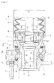
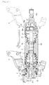
- Fig. 1 is a longitudinal section view showing a first embodiment of an axle module on which a unit cover of the present invention is mounted
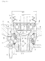
- Fig. 2 is an enlarged longitudinal section view showing a wheel bearing apparatus of Fig. 1
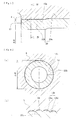
- Fig. 3 is a partially enlarged view of Fig. 2
- Fig. 4(a) is a cross section view along a line IV-IV of Fig. 3
- Fig. 4(b) is a partially enlarged view of Fig. 4(a)
- Fig. 5(a) is a partially enlarged view of a condition before caulking
- Fig. 1 is a longitudinal section view showing a first embodiment of an axle module on which a unit cover of the present invention is mounted
- Fig. 2 is an enlarged longitudinal section view showing a wheel bearing apparatus of Fig. 1
- Fig. 3 is a partially enlarged view of Fig. 2
- Fig. 4(a) is a cross section view along a line IV-IV of Fig. 3
- FIG. 5(b) is a partially enlarged view of a condition after caulking
- Figs. 6(a) and 6(b) are explanatory view showing a gap measuring method during assembly
- Figs. 7(a) and 7(b) are explanatory view showing rotational torque measuring method before and after caulking
- Fig. 8 is a graph showing a relation between a starting torque and an amount of elastic displacement in the axial direction
- Fig. 9 is a graph showing a pre-load amount and a starting torque of the bearing
- Fig. 10 is an explanatory view showing a method for assembling a unit cover of Fig. 1
- Fig. 11 is a longitudinal section view showing another unit cover
- Fig. 12 is an explanatory view showing a method for assembling the axle module and the knuckle
- Fig. 13 is an explanatory view showing another assembling method.
- a term “outer side” (left hand side in the drawings) of the apparatus denotes a side which is positioned outside of the vehicle body
- a term “inner side” (right hand side in the drawings) of the apparatus denotes a side which is positioned inside of the body when the bearing apparatus is mounted on the vehicle body.
- an axle module of the present invention comprises a pair of constant velocity universal joint 1, 2, a wheel bearing apparatus which is formed as a unit of a double row rolling bearing 3 rotationally supporting a wheel (not shown) and the constant velocity universal joint 1 of the outer side, a drive shaft 4 connected to the pair of the constant velocity universal joint 1, 2, and a unit cover 5 for protecting the pair of constant velocity universal joint 1, 2 and the drive shaft 4.
- the double row rolling bearing 3 forming the wheel bearing apparatus has a structure of a so-called fourth generation comprising an inner member 8 including a hub wheel 6 and an outer joint member 7 of the constant velocity universal joint 1, and an outer member 10 inserted around the inner member 8 via double row rolling elements (balls) 9, 9.
- the hub wheel 6 is made of medium carbon steel including carbon of 0.40 ⁇ 0.80%by weight such as S53C and has a wheel mounting flange 11 on its outer side end portion.
- the hub wheel 6 is formed on its outer circumferential surface with an outer side inner raceway surface 6a and a cylindrical portion 6b axially extending from the inner receway surface 6a and on its inner circumferential surface with a recessed and projected portion 12 hardened as having its surface hardness of 54 ⁇ 64 HRC. It is preferable to use as the heat treatment a high frequency induction heating which can easily carry out local heating and setting of the depth of the hardened layer.
- a plurality of hub bolts 13 are mounted on the wheel mounting flange equidistantly spaced along the periphery of the wheel mounting flange 11.
- the recessed and projected portion 12 of the hub wheel 6 comprises a crossed-groove formed by crossing substantially orthogonally a plurality of annular independent grooves 12a formed by turning axially along the inner circumferential surface of the hub wheel 6 and a plurality of axial grooves 12b formed by broaching equidistantly along the inner circumferential surface of the hub wheel 6.
- the crossed-groove may be formed by helical grooves inclined opposite directions each other.
- a bottom diameter d1 of the annular grooves 12a and a bottom diameter d2 of the axial grooves 12b are perfectly equalized and thus the height of the circumferential projections and that of the axial projections are equalized each other so as to form a group of pyramids each having a sharp tip in projections of the recessed and projected portion 12.
- the bottom diameter d1 of the annular grooves 12a is set smaller than the bottom diameter d2 of the axial grooves 12b (d1 ⁇ d2). This enables to improve the machining accuracy by suppress vibration in machining process with avoiding discontinuous cutting during formation of the axial grooves 12b after the formation of the annular grooves 12a.
- each axial groove 12b is formed of the recess (bottom of groove) 12ba of a circular arc and a projection (tip) 12bb is formed of substantially straight lines, and the included angle if the projection 12bb is set to substantially 90°.
- the biting of the recessed and projected portion 12 into the shaft portion 20 is suppressed by projections 12bb formed by linear outline so that the void 34 can be remained in the recess 12ba.
- This enables suppress deformation of the hub wheel 6 and thus excessive stress in the hub wheel 6 and accordingly it is possible to provide the wheel bearing apparatus of the fourth generation type which can keep the durability for a long term and improve its reliability.
- the outer member 10 is made of medium carbon steel including carbon of 0.40 ⁇ 0.80% by weight such as S53C and integrally formed on its outer circumferential surface with a body mounting flange 10b to be mounted on a knuckle (not shown) forming a suspension apparatus of a vehicle and on its inner circumferential surface with double row outer raceway surfaces 10a, 10a.
- the double row outer raceway surfaces 10a, 10a are hardened by high frequency induction quenching so as to have a surface hardness of 58 ⁇ 64 HRC.
- the constant velocity universal joint 1 comprises the outer joint member 7, a joint inner ring 14, a cage 15 and torque transmitting balls 16.
- the outer joint member 7 is made of medium carbon steel including carbon of 0.40 ⁇ 0.80%by weight such as S53C and integrally formed by a cup shaped mouth portion 18 on which a plastic boot 17 is mounted around the periphery of an opening, a shoulder 19 forming a bottom of the mouth portion 18 and formed with the other (inner side) inner raceway surface 7a on its outer circumferential surface, and a hollow shaft portion 20 axially extending from the shoulder portion 19.
- the shaft portion 20 is formed on its outer circumferential surface with a spigot portion 20a fitted into the cylindrical portion 6b of the hub wheel 6 via a predetermined interference and a fitting portion 20b axially extending from the spigot portion 20a.
- leakage of lubricating oil contained in the mouth portion 18 and ingress of rain water or dusts into inside of the joint from the outside can be prevented by the boot 17 and an end cap 21 fitted in the shoulder 19 of the outer joint member 7.
- the mouth portion 18 is formed with on its inner circumferential surface eight curved track grooves 18a and the joint inner ring 14 is formed on its outer circumferential surface with eight track grooves 14a corresponding to the track grooves 18a.
- the torque transmitting balls 16 are contained between the track grooves 18a, 14a and held therein by the cage 15.
- the track grooves 18a, the shoulder portion 19 and the shaft portion 20 are hardened so as to have a surface hardness of 58 ⁇ 64 HRC however the fitting portion 20b of the shaft portion 20 is remained not-hardened.
- Double row balls 9, 9 are contained between the double row inner raceway surfaces 6a, 7a of the inner member 8 and the double row outer raceway surfaces 10a, 10a of the outer member 10 and held therein freely rollably by cages 22, 22.
- Seals 23, 24 are arranged in annular openings formed between the outer member 10 and the hub wheel 6/outer joint member to prevent leakage of lubricating oil contained in the bearing and ingress of rain water or dusts into the bearing from the outside.
- the shaft portion 20 of the outer joint member 7 is press fitted into the hub wheel 6 via the interference fit having a some interference.
- the axial gap of the bearing is set to a negative gap in the pitch dimension P0 and an axial gap S1 is formed between the end face of the cylindrical portion 6b and the shoulder portion 19 of the outer joint member 7.
- the hub wheel 6 and the outer joint member 7 are integrally connected via a plastically deformed caulking by inserting an expanding tool such as a mandrel into the fitting portion 20b of the shaft portion 20 from the outer side, by radially expanding the fitting portion 20b and by biting a hardened recessed and projected portion 12 formed on the inner circumferential surface of the hub wheel 6 into the fitting portion 20b of the shaft portion 20.
- the end face of the cylindrical portion 6b of the hub wheel 6 is butted against the shoulder portion 19 of the outer joint member 7 by the caulking process as shown in Fig. 5(b) .
- P1 P0-P1
- a method for measuring the bearing gap during the assembly of the wheel bearing apparatus will be described using Figs 6 and 7 .
- the outer joint member 7 is press fitted into the cylindrical portion 6b of the hub wheel 6 and stopped once just before the shoulder portion 19 of the outer joint member 7 is butted to the cylindrical portion 6b of the hub wheel 6.
- the axial gap of the bearing is positive and the predetermined axial gap S1 is remained between the cylindrical portion 6b of the hub wheel 6 and the shoulder 19 of the outer joint member 7.
- an axial dimension H0 from a reference surface (end face of the mouth portion 18) 18b of the outer joint member 7 to a reference surface (side face of the flange 11) 11a is measured and an initial axial gap ⁇ 0 of the bearing is measured from an axial shift amount of the outer member 10 relative to the inner member 8.
- the outer joint member 7 is press fitted into the hub wheel 6 until the shoulder portion 19 of the outer joint member 7 abuts against the end face of the cylindrical portion 6b and then an axial dimension H1 from the reference surface 18b of the outer joint member 7 to the reference surface 11a of the hub wheel 6 is measured.
- the axial gap ⁇ 1 of the bearing before the caulking is set negative in this case.
- the rotational torque T1 before the caulking process of the bearing is measured as shown in Fig. 7(a) . That is, the rotational torque of a rotational member "R” is measured by longitudinally placing the wheel bearing apparatus and mounting the rotational member "R” on the body mounting flange 10b of the outer member 10.
- the hub wheel 6 and the outer joint member 7 are integrally connected via a plastically deformed caulking by inserting an expanding tool such as a mandrel into the fitting portion 20b of the shaft portion 20 from the outer side, by radially expanding the fitting portion 20b and by biting a hardened recessed and projected portion 12 formed on the inner circumferential surface of the hub wheel 6 into the fitting portion 20b of the shaft portion 20. Then the rotational torque T2 of the bearing after the caulking is measured by the torque measuring instrument T/S as shown in Fig. 7(b) .
- the negative gap of the bearing is increased by the caulking and the rotational torque T2 after the caulking is increased as compared with the rotational torque T1 before the caulking (T2>T1).
- T2>T1 the measurement of the rotational torque of the bearing is illustrated and described, a starting torque of the bearing may be measured in place of the measurement of the rotational torque.
- the rotational torque T can be obtained by previously setting a relation formula from the relation between the rotational torque and the amount of elastic displacement and then by substituting the axial gap ⁇ 1 after press fitting of the outer joint member 7 into the cylindrical portion 6b of the hub wheel 6 for the relation formula.
- Fig. 8 is an example showing the relation between the starting torque of the bearing and the amount of elastic displacement.
- the amount of elastic displacement of the bearing can be obtained by substituting the rotational torque T3 for the relation formula between the rotational torque and the amount of elastic displacement.
- This amount of elastic displacement becomes the axial gap (negative gap) of the bearing after caulking.
- Fig. 9 is an example showing the relation between the pre-load amount of the bearing and the starting torque.
- the axial gap of the bearing before the caulking is set to the negative gap
- the axial gap of the bearing is obtained by calculating the rotational torque T3 by adding the increment ⁇ T of the rotational torque obtained from the rotational torque T1, T2 respectively measured before and after the caulking to the rotational torque T obtained from the axial gap previously measured ⁇ 1 before the caulking and then by substituting the rotational torque T3 for the relation formula between the rotational torque and the amount of elastic displacement
- the axial gap before the connection between the hub wheel and the outer joint member via plastic deformation can be stably measured by the rotational torque etc. and the bearing gap can be exactly controlled with suppressing the influence of angular run-out of the bearing.
- a region of the outer circumferential surface of the hub wheel 6 forming a seal land portion on which sealing lips of an outer side seal 23 slides and the cylindrical portion 6b is hardened by high frequency induction quenching so as to have a predetermined surface hardness of 58 ⁇ 64 HRC.
- This enables to improve not only the wear resistance of the seal land portion but the mechanical strength and durability of the hub wheel 6 against the rotary bending moment.
- a relation between an outer diameter Da of the fitting surface 10c of the outer member 10 to be fitted into the knuckle and a maximum outer diameter of the joint assembly 32 later mentioned (in this case an outer diameter Db of the unit cover 5) is set as Da ⁇ Db.
- constant velocity universal joint 1 of a compact type using 8 balls the present invention is not limited to such an example and any constant velocity universal joint satisfying the condition Da ⁇ Db may be used and thus a generally used constant velocity universal joint having six balls may be used.
- any type of constant velocity universal joint may be used in the present invention. For example that having straight track grooves and a so-called "undercut free type" constant velocity universal joint may be used if it is a secured type constant velocity universal joint.
- one end of the drive shaft 4 is inserted into the joint inner ring 14 of the outer side constant velocity universal joint 1 via a serration 14b and the other end of the drive shaft 4 is inserted into a tripod member 26 of the slide type constant velocity universal joint 2 connected to a differential apparatus (not shown) via a serration 26b.
- the slide type constant velocity universal joint 2 of inner side comprises the outer joint member 25, the tripod member 26 having three legs 26a equidistantly projected from its outer circumferential surface, and rollers 28 rollably mounted on the legs 26a via needle bearings.
- the outer joint member 25 is made of medium carbon steel including carbon of 0.40 ⁇ 0.80%by weight such as S53C and comprises a hollow cylindrical portion 29 and a shaft portion 30 extending from the bottom of the cylindrical portion 29.
- the shaft portion 30 is formed on its outer circumferential surface with serration 30a to be connected to the differential apparatus.
- Three axially extending straight track grooves 29a are formed on the inner circumferential surface of the cylindrical portion 29 and the rollers 28 roll on the track groove 29a.
- the surfaces of the track grooves 29a and the shaft 30 are hardened by high frequency induction quenching so as to form a predetermined hardened layer of 58 ⁇ 64 HRC.
- An opening of the cylindrical portion 29 is covered by a boot 31 of synthetic rubber to prevent leakage of grease contained in the cylindrical portion 29 and ingress of rain water and dusts from outside into the joint member 25.
- any sliding type constant velocity universal joint may be used for example as other tripod type having a different structure and a double offset type constant velocity universal joint (DOJ).
- DOJ double offset type constant velocity universal joint
- a cylindrical unit cover 5 is mounted on the outer joint members7, 25 of the pair of constant velocity universal joints 1, 2 respectively for covering the outer circumferential surfaces of the constant velocity universal joints 1, 2 and the drive shaft 4 (hereinafter referred to as "joint assembly").
- the unit cover 5 is made by injection molding of elastomer such as PA (polyamide) 66 and formed of a two-separated structure comprising an upper cover 5a and an under cover 5b as shown in Fig. 10 .
- the unit cover 5 has a straight cylindrical outer surface and an inner surface formed as having a configuration corresponding to outlines of the outer joint members 7, 25 and boots 17, 31. This enables to protect the joint assembly 32 and to prevent the constant velocity universal joints from being hung down by their own weight. Accordingly it is possible to provide an axle module which is easy in handling during its transportation and assembly and can improve the workability in its assembly to a vehicle.
- unit cover 5 is shown as an upper and lower two separated type, any other types of unit cover may be used in the present invention which can be radially separated and mounted on the joint assembly from the outside thereof.
- three separated type of unit cover may be used or a two separated type in which two halves are connected each other by a hinge may be also used.
- the unit cover 5 may be made of suitable material e.g. POM (polyacetal), PBT (polybutyleneterephthalate), PET (polyethyleneterephthalate) etc. other than PA 66.
- the material forming the unit cover 5 is not limited to these thermoplastic resin and other material of low price and good formability such as synthetic rubber having a predetermined rigidity may be also used.
- the outline configuration of the unit cover 5 is not limited to a cylinder and a configuration shown in Fig. 11 may be used.
- This unit cover 33 has an inner circumferential surface having a configuration corresponding to outlines of the outer joint members 7, 25 and boots 17, 31 similarly to the unit cover 5 previously described and an outer circumferential surface of a streamlined configuration recessed at its substantially center in an axial direction. This enables to improve the workability of assembling the axle module to a knuckle and to reduce the weight and size of the axle module.
- Fig. 12 is an explanatory drawing showing a method for mounting the knuckle "N" to the axle module comprising the wheel bearing apparatus including the joint assembly 32. Since the unit cover 5 is mounted on the joint assembly 32, the constant velocity universal joints 1, 2 are prevented from being hung down by their own weight and thus their angular attitude is stabled. Accordingly it is possible to smoothly insert the knuckle "N" from the inner side constant velocity universal joint 2 toward the body mounting flange 10b of the outer member 10 along the outer surface of the unit cover 5 as shown by an arrow. Further it is possible to prevent the axle module from being contaminated or damaged and thus to keep the mounted condition in place until assembly of a corner module of suspension apparatus or a vehicle is carried out.
- Fig. 14 is a longitudinal section view showing a second embodiment of an axle module of the present invention
- Fig. 15 is a longitudinal section view showing a wheel bearing apparatus of Fig. 14
- Fig. 16(a) is a longitudinal section view showing a knuckle of the present invention
- Fig. 16(b) is a front elevation view thereof
- Fig. 17 is an explanatory view showing a method for assembling the axle module of the present invention to a vehicle.
- Same reference numerals are used herein for designating same parts as those having same functions used in the first embodiment.
- This axle module of the present invention is intended to transmit a power from an engine to a wheel and to rotationally support the wheel relative to a suspension apparatus of a vehicle.
- the fundamental structure of the axle module comprises a wheel bearing apparatus formed as a unit of the hub wheel 6, the double row rolling bearing 3 and the secured type constant velocity universal joint 1; and the slide type constant velocity universal joint 2 connected to the constant velocity universal joint 1 via the drive shaft 4.
- the maximum outer diameter Dc of the constant velocity universal joint 2 forms an outer diameter of a boot 31.
- the wheel bearing apparatus has a structure of the fourth generation type in which the hub wheel 6, the double row rolling bearing 3, and the constant velocity universal joint 1 is formed as a unit.
- the outer member 10 of the double row rolling bearing 3 is integrally formed on its outer circumferential surface with the body mounting flange 10b to be mounted on the knuckle N1 forming part of the suspension apparatus and the fitting surface 10c to be fitted into the knuckle N1 is formed on the body mounting flange 10b at the inner side thereof.
- a bellows shaped boot 17 for example of thermoplastic resin is mounted on the outer circumferential portion at an opening side of the mouth portion 18 and on the drive shaft 4.
- the boot 17 allows the outer joint member 7 to bend relative to the drive shaft 4 and prevents cooperating with the end cap 21 mounted on the hollow shaft portion 20 grease contained within the mouth portion 18 from being leaked therefrom and rain water or dusts from entering into the inside of the bearing.
- a boot 17 of plastic resin has high strength and durability, its rigidity is higher than that of a conventional boot made of synthetic resin and thus it is necessary to fasten its opened end by a boot band 35.
- This boot band 35 is formed on its outer circumferential surface with circumferentially extending pleats (not shown) and also formed on a portion of the outer circumferential surface with a projection 35a.
- the projection 35a is caulked to reduce the diameter of the boot band 35 in order to uniformly and rigidly fasten the boot 17.
- the projection 35a project radially outward larger than the outer diameter of the boot 17 which forms the maximum outer diameter Db of the constant velocity universal joint 1. Accordingly since the outer diameter of the projection 35a is larger than the outer diameter (i.e. the inner diameter of the knuckle N1) Da of the fitting surface 10c of the outer member 10, the knuckle N1 cannot pass through the outer diameter of the constant velocity universal joint 1 and thus assembly of the wheel bearing apparatus to a vehicle is impossible.
- the knuckle N1 comprises a securing portion 36 adapted to be fitted onto the fitting surface 10c of the outer member 10 and a connecting portion 37 including arms 37a, 37b, 37c to be connected to a suspension apparatus (not shown).
- the securing portion 36 is formed with bolt apertures 36a for securing bolts (not shown) and an axially extending slit 38 having a substantially rectangular cross section and for permitting passage of the projection 35a of the boot band 35.
- This slit 38 enables to assemble the constant velocity universal joint 1 to a vehicle by inserting it into the knuckle N1 without the knuckle N1 interfering the boot band 35 only by aligning the position of the projection 35a with that of the slit 38.
- the maximum outer diameter of the inner side constant velocity universal joint 2 in this case the outer diameter of the boot 31) Dc is set smaller than the maximum outer diameter of the outer side constant velocity universal joint 1 (in this case the outer diameter of the boot 17) Db
- the axle module comprising the pair of constant velocity universal joints 1, 2, the drive shaft 4 connected to these constant velocity universal joints 1, 2, and the wheel bearing apparatus as a unit to a vehicle.
- it is possible to easily assemble the axle module to the knuckle N1 to realize modularization of a suspension and its related parts, and thus to further improve the workability in assembly of a vehicle.
- a method for inserting the knuckle N1 onto the axle module using Fig. 17 Firstly the knuckle N1 is passed over the constant velocity universal joint 2 from the inner side (right hand side in Fig. 17 ) thereof. Then the knuckle N1 is moved toward the constant velocity universal joint 1 with aligning the slit 38 formed on the knuckle N1 with the projection 35a of the boot band 35. Then the knuckle N1 is fitted on the fitting surface 10c of the outer member 10, and finally the knuckle N1 is fastened to the outer member 10 by bolts (not shown).
- the knuckle N1 is formed with the slit 38 allowing passage of the projection 35a of the boot band 35, it is possible to pass the knuckle N1 over the axle module and thus to reduce the weight and size of the knuckle N1 and its related suspension parts as well as to improve the workability in assembly of the axle module to a vehicle.
- the wheel bearing apparatus of the present invention can be applied to the wheel bearing apparatus of the fourth generation type in which the hub wheel forming the bearing portion and the outer joint member of the constant velocity universal joint are united each other via plastic deformation between them.
- the unit cover is mounted on constant velocity universal joints and a drive shaft connected thereto forming a power transmitting apparatus of a vehicle for protecting the constant velocity universal joints and improving the workability in assembly thereof and can be applied to an axle module of any power transmitting apparatus despite of types of the constant velocity universal joints and wheel bearings connected thereto.
Landscapes
- Engineering & Computer Science (AREA)
- Mechanical Engineering (AREA)
- General Engineering & Computer Science (AREA)
- Chemical & Material Sciences (AREA)
- Combustion & Propulsion (AREA)
- Transportation (AREA)
- Rolling Contact Bearings (AREA)
Abstract
Description
- The present invention relates to a joint assembly comprising a pair of constant velocity universal joints and a drive shaft connected to them; a wheel bearing apparatus formed of a united combination of a secured type constant velocity universal joint and a double row rolling bearing for rotationally supporting a wheel of vehicle relative to a knuckle forming a suspension apparatus; and a wheel bearing assembly (hereinafter referred to as an "axle module) having them.
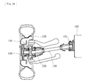
- A power transmitting apparatus for transmitting an engine power of vehicle such as an automobile etc. to wheels is required not only to transmit the engine power to wheels but to allow radial and axial displacements and a moment displacement of wheels caused by bounds of wheel or turning of vehicle during running on a rough road. Accordingly as shown in
Fig. 18 , an engine side (e.g. a transmission) and a wheel are connected via adrive shaft 100 one end of which is connected to adifferential apparatus 102 via a slide type constant velocityuniversal joint 101 and the other end of which is connected to awheel 105 via awheel bearing apparatus 104 including a secured type constant velocityuniversal joint 103. - The wheel bearing
apparatus 104 comprises a so-called "third generation" type wheel bearing 106 and the secured type constant velocityuniversal joint 103 detachably connected to thewheel bearing apparatus 106. In recent years it is a tendency that the third generation structure is shifted to a so-called "fourth generation" structure in which the wheel bearing 106 and the secured type constant velocityuniversal joint 103 are combined as a unit. - In an axle module in which a wheel bearing apparatus of the fourth generation, a constant velocity universal joint forming the wheel bearing apparatus and a drive shaft connected to a pair of constant velocity universal joint including said constant velocity universal joint are combined as a unit, it is known that further combine a unit cover for improving the workability of assembly of the axle module to a vehicle as well as for protecting a boots of the constant velocity universal joint during assembly and transportation of the axle module. As shown in
Fig. 19 such an axle module is formed by a wheel bearing apparatus comprising anouter member 50 formed on its outer circumferential surface with abody mounting flange 50b adapted to be mounted on a knuckle "N" afitting surface 50c to be inserted into the knuckle "N" and on its inner circumferential surface with double rowouter raceway surfaces inner member 55 including ahub wheel 53 inserted into theouter member 50 viadouble row balls wheel mounting flange 52 and on its outer circumferential surface with oneinner raceway surface 53a opposite to one of the double rowouter raceway surfaces outer joint member 54 formed on its outer circumferential surface with anotherinner raceway surface 54a opposite to the other one of the double rowouter raceway surfaces fitting surface 50c is formed larger than the maximum outer diameter of the constant velocity universal joint and aunit cover 57 of elastomer formed as a cylindrical member for covering the periphery of the joint assembly "JA" and formed with contractedportions universal joints drive shaft 59 connected to these constant velocityuniversal joints - The provision of the
unit cover 57 for covering the periphery of the joint assembly "JA" enables to protect the joint assembly "JA" and to make a handling such as transportation easy. In addition provision of the elastic contractedportions unit cover 57 enables to easily mount by a "one-touch" manner "theunit cover 57 onto theouter joint member 54 of the constant velocityuniversal joint 56 and to prevent theunit cover 57 from being fallen out (see Japanese Laid-open Patent Publication No.256938/2005 - In such an axle module of the prior art, the constant velocity
universal joints unit cover 57 of the prior art cannot prevent the hanging down of them, it is difficult to assemble the axle module to the knuckle "N" and to handle it during its packaging or transportation. - It is, therefore, an object of the present invention to provide a joint assembly comprising a pair of constant velocity universal joints and a drive shaft connecting them which can protect the constant velocity universal joints and prevent the hanging down of them by their own weight.
- An other object of the present invention is to provide a wheel bearing apparatus which can reduce its weight and size and can improve the workability in assembly of it to a vehicle.
- A further object of the present invention is to provide an axle module which can improve the workability in assembly of it to a vehicle and to simplify the assembly and transportation of it.
- For achieving the objects of the present invention above, there is provided a joint assembly comprising a pair of constant velocity universal joints and a drive shaft connected to the constant velocity universal joints in which: one constant velocity universal joint of the pair of constant velocity universal joints is a secured type constant velocity universal joint and includes: an outer joint member formed on its inner circumferential surface with a plurality of curved and axially extending track grooves; a joint inner ring formed on its outer circumferential surface with track grooves oppositely to the track grooves; torque transmitting balls contained within ball tracks formed by the track grooves; a cage for rollably holding the torque transmitting balls within the ball tracks; the drive shaft one end of which being connected to the joint inner ring, and a boot mounted on the drive shaft and on an outer circumferential portion at an opened side of the outer joint member; and the other constant velocity universal joint of the pair of constant velocity universal joints is a slide type constant velocity universal joint and connected to the other end of the drive shaft characterized in that a cylindrical unit cover is arranged so that it covers outer circumferential surfaces of the pair of constant velocity universal joints and boots thereof, the unit cover being formed of elastomer by injection molding and having on its inner circumferential surface a configuration corresponding to configurations of outlines of the pair of constant velocity universal joints and the boots (claim 1).
- According to the joint assembly comprising a pair of constant velocity universal joints and a drive shaft connected to the constant velocity universal joints of the present invention of
claim 1, since the cylindrical unit cover is arranged so that it covers outer circumferential surfaces of the pair of constant velocity universal joints and boots thereof, the unit cover being formed of elastomer by injection molding and having on its inner circumferential surface a configuration corresponding to configurations of outlines of the pair of constant velocity universal joints and the boots, it is possible to protect the constant velocity universal joints and prevent the hanging down of them by their own weight. - It is preferable as defined in
claim 2 that the unit cover is separated in its radial direction. This enables assembly of the unit cover easy. - It is also preferable as defined in
claim 3 that the unit cover is formed so that it has an outline of a streamlined configuration recessed at its substantially center in an axial direction. This enables to further improve the workability in assembly of the axle module to the knuckle and to reduce the weight and size thereof. - According to the present invention there is also provided an axle module comprising: a wheel bearing apparatus, the wheel bearing including: an outer member formed on its outer circumferential surface with a body mounting flange adapted to be mounted on a knuckle forming a portion of a suspension apparatus and a fitting surface and on its inner circumferential surface with double row outer raceway surfaces; an inner member including a hub wheel integrally formed on its one end with a wheel mounting flange and on its outer circumferential surface with one inner raceway surface opposite to one of the double row outer raceway surfaces and also including an outer joint member of the constant velocity universal joint adapted to be fitted into the hub wheel and formed on its outer circumferential surface with another inner raceway surface opposite to the other one of the double row outer raceway surfaces; and a plurality of rolling elements freely rollably contained between the inner member and the outer member; a joint assembly connected to the hub wheel via a torque transmittable manner; and a unit cover for covering the joint assembly characterized in that the outer diameter of the fitting surface of the outer member is formed larger than the outer diameter of the unit cover (claim 4).
- According to the axle module of the present invention of
claim 4, since the outer diameter of the fitting surface of the outer member is formed larger than the outer diameter of the unit cover, it is possible to make the assembly and transportation of the axle module easy and simple and thus to improve the assembly of it to a vehicle. - Further according to the present invention there is provided a wheel bearing apparatus of united combination of a hub wheel, a double row rolling bearing and a constant velocity universal joint comprising: an outer member integrally formed on its outer circumferential surface with a body mounting flange and on its inner circumferential surface with double row outer raceway surfaces; an inner member including a hub wheel integrally formed on its one end with a wheel mounting flange and on its outer circumferential surface with one inner raceway surface opposite to one of the double row outer raceway surfaces and a cylindrical portion axially extending from the one inner raceway surface and also including an outer joint member forming the constant velocity universal joint formed on its outer circumferential surface with another inner raceway surface opposite to the other one of the double row outer raceway surfaces and a shaft portion axially extending from the another inner raceway surface and being adapted to be fitted into the hub wheel; and a plurality of rolling elements freely rollably contained between the inner and outer raceway surfaces respectively of the inner member and the outer member, the hub wheel and the outer joint member being integrally connected via a plastically deformed caulking by radially expanding a fitting portion of the shaft portion of the outer joint member and by biting a hardened recessed and projected portion formed on the inner circumferential surface of the hub wheel into the outer circumferential surface of the shaft portion of the outer joint member characterized in that the recessed and projected portion is a crossed-groove formed by crossing substantially orthogonally a plurality of annular independent grooves formed axially along the inner circumferential surface of the hub wheel and a plurality of axial grooves formed equidistantly along the inner circumferential surface of the hub wheel, and that the biting of the hardened recessed and projected portion of the hub wheel into the shaft portion of the outer joint member is performed so that the material of the shaft portion does not extend to the bottoms of the axial grooves and thus voids are remained in the recessed portions of the axial grooves (claim 5).
- In the wheel bearing apparatus of the fourth generation type in which the hub wheel and the outer joint member are plastically connected each other by caulking of radial expansion of the shaft portion of the outer joint member, since the recessed and projected portion is a crossed-groove formed by crossing substantially orthogonally a plurality of annular independent grooves formed axially along the inner circumferential surface of the hub wheel and a plurality of axial grooves formed equidistantly along the inner circumferential surface of the hub wheel, and that the biting of the hardened recessed and projected portion of the hub wheel into the shaft portion of the outer joint member is performed so that the material of the shaft portion does not extend to the bottoms of the axial grooves and thus voids are remained in the recessed of the axial grooves, it is possible to provide a wheel bearing apparatus of the fourth generation type which can suppress deformation of the hub wheel and thus generation of excessive stress in the hub wheel and has high durability and reliability for a long term.
- It is preferable as defined in
claim 6 that the cross sectional configuration of each axial groove is formed of the recess of a circular arc and a projection of substantially straight lines, and wherein the biting of the recessed and projected portion into the shaft portion is suppressed by the projections so that the void can be remained in the recess. This enables to suppress deformation of the hub wheel and thus generation of excessive stress in the hub wheel. - It is also preferable as defined in
claim 7 that the included angle if the projection is set to substantially 90°. This enables to increase the biting power and thus the reliability of connection between the hub wheel and the outer joint member. - It is preferable as defined in
claim 8 that the diameter d1 of the bottom of the annular groove is set smaller than the diameter d2 of the bottom of the axial groove (i.e. d1≤d2). This enables to improve an accuracy of machining during formation of the axial grooves using a broach after formation of the annular grooves with avoiding discontinuous cutting of the broach and suppressing vibrations during the machining. - According to the present invention there is also provided a wheel bearing apparatus comprising: an outer member integrally formed on its outer circumferential surface with a body mounting flange and on its inner circumferential surface with double row outer raceway surfaces; an inner member including a hub wheel integrally formed on its one end with a wheel mounting flange and on its outer circumferential surface with one inner raceway surface opposite to one of the double row outer raceway surfaces and also including an outer joint member of the constant velocity universal joint formed on its outer circumferential surface with another inner raceway surface opposite to the other one of the double row outer raceway surfaces; and a plurality of rolling elements freely rollably contained between the inner member and the outer member; the hub wheel and the outer joint member being integrally connected via a plastic deformation characterized in that the axial gap of the bearing between the hub wheel and the outer joint member before the plastically deformed connection of them is set to become a negative gap (claim 9).
- In the wheel bearing apparatus in which the inner member i.e. the hub wheel and the outer joint member are integrally connected via the plastic deformation, since axial gap of the bearing between the hub wheel and the outer joint member before the plastically deformed connection of them is set to become a negative gap, it is possible to stably measure the axial gap before the connection via plastic deformation e.g. using a rotational torque, to suppress influences of an angular run-out of the bearing, and to accurately control the bearing gap.
- It is preferable as defined in
claim 10 that the negative gap between the hub wheel and the outer joint member before the plastically deformed connection of them is increased by the plastically deformed connection and set to a predetermined axial gap therebetween. This makes it possible to exactly and stably measure an amount of gap variation due to plastic deformation machining and thus to obtain an optimum axial gap as well as to extend the service life of the bearing. - Further according to the present invention there is provided a wheel bearing apparatus comprising: an outer member integrally formed with a body mounting flange adapted to be mounted on a knuckle and formed on its inner circumferential surface with double row outer raceway surfaces; an inner member including a hub wheel freely rollably supported on the outer member and integrally formed on its one end with a wheel mounting flange and on its outer circumferential surface with one inner raceway surface opposite to one of the double row outer raceway surfaces and a cylindrical portion axially extending from the one inner raceway surface and also including an outer joint member of the constant velocity universal joint formed on its outer circumferential surface with another inner raceway surface opposite to the other one of the double row outer raceway surfaces and a shaft portion axially extending from the another inner raceway surface and being adapted to be fitted into the hub wheel; and a plurality of rolling elements freely rollably contained between the inner member and the outer member; the hub wheel and the outer joint member being integrally connected via a plastic deformation by caulking the shaft portion of the outer joint member onto the inner circumferential surface of the hub wheel characterized in that an axially extending slit having a substantially rectangular cross section is formed on the inner circumferential surface of the knuckle, that a boot is mounted on the outer joint member, that a boot band for fastening the boot has on its outer circumferential surface a projection projected radially outward beyond the maximum outer diameter of the constant velocity universal joint, that the boot is secured on the outer joint member by caulking the projection to reduce the diameter of the boot band, and that the configuration and dimension of the projection are determined so that the projection can pass through the slit of the knuckle (claim 11).
- According to the wheel bearing apparatus of
claim 11, since an axially extending slit having a substantially rectangular cross section is formed on the inner circumferential surface of the knuckle, a boot is mounted on the outer joint member, that a boot band for fastening the boot has on its outer circumferential surface a projection projected radially outward beyond the maximum outer diameter of the constant velocity universal joint, the boot is secured on the outer joint member by caulking the projection to reduce the diameter of the boot band, and the configuration and dimension of the projection are determined so that the projection can pass through the slit of the knuckle, it is possible to arrange the knuckle around the wheel bearing apparatus and thus to provide a wheel bearing apparatus which can reduce the weight and size of the knuckle and suspension apparatus and improve the workability in assembly of the wheel bearing apparatus to a vehicle. - It is preferable as defined in
claim 12 that the hub wheel and the outer joint member being integrally connected via a plastically deformed caulking by radially expanding the shaft portion of the outer joint member and by biting a hardened recessed and projected portion formed on the inner circumferential surface of the hub wheel into the outer circumferential surface of the shaft portion of the outer joint member. This makes it possible to reduce the weight and size of the wheel bearing apparatus, to improve the strength and durability of the hub wheel, and to keep the pre-load amount of the hub wheel for a long term. - Further according to the present invention there is provided an axle module comprising: said wheel bearing apparatus; a pair of constant velocity universal joints including a secured type constant velocity universal joint forming the wheel bearing apparatus and a slide type constant velocity universal joint of the inner side; and a drive shaft connected to the pair of constant velocity universal joints characterized in that the maximum outer diameters of the pair of constant velocity universal joints are set smaller than the inner diameter of the knuckle (claim 13). This makes it possible to arrange the knuckle around the wheel bearing apparatus and thus to provide a wheel bearing apparatus which can reduce the weight and size of the knuckle and suspension apparatus and improve the workability in assembly of the wheel bearing apparatus to a vehicle.
- It is also preferable as defined in
claim 14 that the constant velocity universal joint of the inner side is formed of a tripod type constant velocity universal joint comprising an outer joint member including a cylindrical member, a shoulder forming the bottom of the cylindrical member, and a shaft portion axially extending from the shoulder; a tripod member having on its outer circumferential portion three legs projected radially outward therefrom spaced equidistantly each other; and rollers freely rollably mounted on the legs. This makes it possible to easily set the maximum outer diameter of the tripod type constant velocity universal joint smaller than that of the secured type constant velocity universal joint. - The best mode for carrying out the present invention is an axle module comprising: a wheel bearing apparatus, the wheel bearing including: an outer member formed on its outer circumferential surface with a body mounting flange adapted to be mounted on a knuckle forming a portion of a suspension apparatus and a fitting surface and on its inner circumferential surface with double row outer raceway surfaces; an inner member including a hub wheel integrally formed on its one end with a wheel mounting flange and on its outer circumferential surface with one inner raceway surface opposite to one of the double row outer raceway surfaces and also including an inner ring or outer joint member of the constant velocity universal joint adapted to be fitted onto or into the hub wheel and formed on its outer circumferential surface with another inner raceway surface opposite to the other one of the double row outer raceway surfaces; and a plurality of rolling elements freely rollably contained between the inner member and the outer member; a secured type joint connected to the hub wheel via a torque transmittable manner; a drive shaft one end of which is connected to the constant velocity universal joint; and further comprising a joint assembly including a slide type constant velocity universal joint; characterized in that a cylindrical unit cover is arranged so that it covers outer circumferential surfaces of the pair of constant velocity universal joints and boots thereof, the unit cover being formed of elastomer by injection molding and having on its inner circumferential surface a configuration corresponding to configurations of outlines of the pair of constant velocity universal joints and the boots; and that the outer diameter of the fitting surface of the outer member is formed larger than the outer diameter of the unit cover.
- Preferable embodiments of the present invention will be hereinafter described with reference to the drawings.
Fig. 1 is a longitudinal section view showing a first embodiment of an axle module on which a unit cover of the present invention is mounted,Fig. 2 is an enlarged longitudinal section view showing a wheel bearing apparatus ofFig. 1 ,Fig. 3 is a partially enlarged view ofFig. 2 ,Fig. 4(a) is a cross section view along a line IV-IV ofFig. 3, and Fig. 4(b) is a partially enlarged view ofFig. 4(a) ,Fig. 5(a) is a partially enlarged view of a condition before caulking, andFig. 5(b) is a partially enlarged view of a condition after caulking,Figs. 6(a) and 6(b) are explanatory view showing a gap measuring method during assembly,Figs. 7(a) and 7(b) are explanatory view showing rotational torque measuring method before and after caulking,Fig. 8 is a graph showing a relation between a starting torque and an amount of elastic displacement in the axial direction,Fig. 9 is a graph showing a pre-load amount and a starting torque of the bearing,Fig. 10 is an explanatory view showing a method for assembling a unit cover ofFig. 1 ,Fig. 11 is a longitudinal section view showing another unit cover,Fig. 12 is an explanatory view showing a method for assembling the axle module and the knuckle, andFig. 13 is an explanatory view showing another assembling method. In the description below, a term "outer side" (left hand side in the drawings) of the apparatus denotes a side which is positioned outside of the vehicle body and a term "inner side" (right hand side in the drawings) of the apparatus denotes a side which is positioned inside of the body when the bearing apparatus is mounted on the vehicle body. - As shown in
Fig. 1 , an axle module of the present invention comprises a pair of constant velocityuniversal joint universal joint 1 of the outer side, adrive shaft 4 connected to the pair of the constant velocityuniversal joint unit cover 5 for protecting the pair of constant velocityuniversal joint drive shaft 4. - As shown in
Fig. 2 the double row rolling bearing 3 forming the wheel bearing apparatus has a structure of a so-called fourth generation comprising aninner member 8 including ahub wheel 6 and anouter joint member 7 of the constant velocityuniversal joint 1, and anouter member 10 inserted around theinner member 8 via double row rolling elements (balls) 9, 9. Thehub wheel 6 is made of medium carbon steel including carbon of 0.40∼0.80%by weight such as S53C and has awheel mounting flange 11 on its outer side end portion. Thehub wheel 6 is formed on its outer circumferential surface with an outer sideinner raceway surface 6a and acylindrical portion 6b axially extending from theinner receway surface 6a and on its inner circumferential surface with a recessed and projectedportion 12 hardened as having its surface hardness of 54∼64 HRC. It is preferable to use as the heat treatment a high frequency induction heating which can easily carry out local heating and setting of the depth of the hardened layer. A plurality ofhub bolts 13 are mounted on the wheel mounting flange equidistantly spaced along the periphery of thewheel mounting flange 11. - As shown in
Figs. 3 and 4 , the recessed and projectedportion 12 of thehub wheel 6 comprises a crossed-groove formed by crossing substantially orthogonally a plurality of annularindependent grooves 12a formed by turning axially along the inner circumferential surface of thehub wheel 6 and a plurality ofaxial grooves 12b formed by broaching equidistantly along the inner circumferential surface of thehub wheel 6. Although not shown in drawings, the crossed-groove may be formed by helical grooves inclined opposite directions each other. - It is preferable that a bottom diameter d1 of the
annular grooves 12a and a bottom diameter d2 of theaxial grooves 12b are perfectly equalized and thus the height of the circumferential projections and that of the axial projections are equalized each other so as to form a group of pyramids each having a sharp tip in projections of the recessed and projectedportion 12. However it is difficult in fact to equalize the bottom diameters d1, d2 each other since machined surfaces formed by turning and broaching exist in a mingled manner. Accordingly in the present invention the bottom diameter d1 of theannular grooves 12a is set smaller than the bottom diameter d2 of theaxial grooves 12b (d1≤d2). This enables to improve the machining accuracy by suppress vibration in machining process with avoiding discontinuous cutting during formation of theaxial grooves 12b after the formation of theannular grooves 12a. - According to the present invention the amount of radial expansion of the
fitting portion 20b of theshaft portion 20 is suppressed so that the material of theshaft portion 20 does not extend to the bottoms of theaxial grooves 12b and thus voids 34 are remained in the recessed portions 12ba of theaxial grooves 12b as shown inFig. 4(b) . More in detail, the cross sectional configuration of eachaxial groove 12b is formed of the recess (bottom of groove) 12ba of a circular arc and a projection (tip) 12bb is formed of substantially straight lines, and the included angle if the projection 12bb is set to substantially 90°. The biting of the recessed and projectedportion 12 into theshaft portion 20 is suppressed by projections 12bb formed by linear outline so that the void 34 can be remained in the recess 12ba. This enables suppress deformation of thehub wheel 6 and thus excessive stress in thehub wheel 6 and accordingly it is possible to provide the wheel bearing apparatus of the fourth generation type which can keep the durability for a long term and improve its reliability. - The
outer member 10 is made of medium carbon steel including carbon of 0.40∼0.80% by weight such as S53C and integrally formed on its outer circumferential surface with abody mounting flange 10b to be mounted on a knuckle (not shown) forming a suspension apparatus of a vehicle and on its inner circumferential surface with double rowouter raceway surfaces outer raceway surfaces - The constant velocity
universal joint 1 comprises the outerjoint member 7, a jointinner ring 14, acage 15 andtorque transmitting balls 16. The outerjoint member 7 is made of medium carbon steel including carbon of 0.40∼0.80%by weight such as S53C and integrally formed by a cup shapedmouth portion 18 on which aplastic boot 17 is mounted around the periphery of an opening, ashoulder 19 forming a bottom of themouth portion 18 and formed with the other (inner side)inner raceway surface 7a on its outer circumferential surface, and ahollow shaft portion 20 axially extending from theshoulder portion 19. Theshaft portion 20 is formed on its outer circumferential surface with aspigot portion 20a fitted into thecylindrical portion 6b of thehub wheel 6 via a predetermined interference and afitting portion 20b axially extending from thespigot portion 20a. In addition leakage of lubricating oil contained in themouth portion 18 and ingress of rain water or dusts into inside of the joint from the outside can be prevented by theboot 17 and anend cap 21 fitted in theshoulder 19 of the outerjoint member 7. - The
mouth portion 18 is formed with on its inner circumferential surface eightcurved track grooves 18a and the jointinner ring 14 is formed on its outer circumferential surface with eighttrack grooves 14a corresponding to thetrack grooves 18a. Thetorque transmitting balls 16 are contained between thetrack grooves cage 15. Thetrack grooves 18a, theshoulder portion 19 and theshaft portion 20 are hardened so as to have a surface hardness of 58∼64 HRC however thefitting portion 20b of theshaft portion 20 is remained not-hardened. -
Double row balls inner raceway surfaces inner member 8 and the double rowouter raceway surfaces outer member 10 and held therein freely rollably bycages Seals outer member 10 and thehub wheel 6/outer joint member to prevent leakage of lubricating oil contained in the bearing and ingress of rain water or dusts into the bearing from the outside. - The
shaft portion 20 of the outerjoint member 7 is press fitted into thehub wheel 6 via the interference fit having a some interference. In this condition, as shown inFig. 5(a) , the axial gap of the bearing is set to a negative gap in the pitch dimension P0 and an axial gap S1 is formed between the end face of thecylindrical portion 6b and theshoulder portion 19 of the outerjoint member 7. Then thehub wheel 6 and the outerjoint member 7 are integrally connected via a plastically deformed caulking by inserting an expanding tool such as a mandrel into thefitting portion 20b of theshaft portion 20 from the outer side, by radially expanding thefitting portion 20b and by biting a hardened recessed and projectedportion 12 formed on the inner circumferential surface of thehub wheel 6 into thefitting portion 20b of theshaft portion 20. The end face of thecylindrical portion 6b of thehub wheel 6 is butted against theshoulder portion 19 of the outerjoint member 7 by the caulking process as shown inFig. 5(b) . Accordingly the axial gap of the bearing is further increased by a gap S1 as a negative gap and become a predetermined axial gap of a pitch dimension P1 (P1= P0-P1). Thus it is possible to easily and stably control the negative gap of the bearing since the axial gap of the bearing can be additionally reduced by the caulking process. - Then a method for measuring the bearing gap during the assembly of the wheel bearing apparatus will be described using
Figs 6 and7 . As shown inFig. 6(a) , the outerjoint member 7 is press fitted into thecylindrical portion 6b of thehub wheel 6 and stopped once just before theshoulder portion 19 of the outerjoint member 7 is butted to thecylindrical portion 6b of thehub wheel 6. At this point of time, the axial gap of the bearing is positive and the predetermined axial gap S1 is remained between thecylindrical portion 6b of thehub wheel 6 and theshoulder 19 of the outerjoint member 7. In this condition, an axial dimension H0 from a reference surface (end face of the mouth portion 18) 18b of the outerjoint member 7 to a reference surface (side face of the flange 11) 11a is measured and an initial axial gapδ0 of the bearing is measured from an axial shift amount of theouter member 10 relative to theinner member 8. - As shown in
Fig. 6(b) , the outerjoint member 7 is press fitted into thehub wheel 6 until theshoulder portion 19 of the outerjoint member 7 abuts against the end face of thecylindrical portion 6b and then an axial dimension H1 from thereference surface 18b of the outerjoint member 7 to thereference surface 11a of thehub wheel 6 is measured. Thus theaxial gap 5 in this case can be calculated from a following formula: δ1=δ0- ( H0 - H1 ) . According to the present invention the axial gapδ1 of the bearing before the caulking is set negative in this case. It is possible to stop the press fitting of the outerjoint member 7 with remaining a slight axial gap in place of press fitting the outerjoint member 7 into thehub wheel 6 until theshoulder 19 is abutted against thecylindrical portion 6b and to obtain a desirable bearing gap (negative gap) by pushing the outerjoint member 7 toward the outer side by caulking process and then by abutting theshoulder portion 19 of the outerjoint member 7 against thecylindrical portion 6b of thehub wheel 6. - On the other hand, the rotational torque T1 before the caulking process of the bearing is measured as shown in
Fig. 7(a) . That is, the rotational torque of a rotational member "R" is measured by longitudinally placing the wheel bearing apparatus and mounting the rotational member "R" on thebody mounting flange 10b of theouter member 10. In this case, since the rotational torque T1 of the bearing before the caulking can be measured by a torque measuring instrument T/S with setting the axial gapδ1 to a negative gap and rotating the rotational member "R" by engaging the rotational member "R" with abolt inserting aperture 10c formed in thebody mounting flange 10b, it is possible to stabilize the measurement of rotational torque, to suppress an influence of the angular run-out of the bearing to the measurement and thus to accurately measure the rotational torque. - Then the
hub wheel 6 and the outerjoint member 7 are integrally connected via a plastically deformed caulking by inserting an expanding tool such as a mandrel into thefitting portion 20b of theshaft portion 20 from the outer side, by radially expanding thefitting portion 20b and by biting a hardened recessed and projectedportion 12 formed on the inner circumferential surface of thehub wheel 6 into thefitting portion 20b of theshaft portion 20. Then the rotational torque T2 of the bearing after the caulking is measured by the torque measuring instrument T/S as shown inFig. 7(b) . According to the present invention the negative gap of the bearing is increased by the caulking and the rotational torque T2 after the caulking is increased as compared with the rotational torque T1 before the caulking (T2>T1). Although the measurement of the rotational torque of the bearing is illustrated and described, a starting torque of the bearing may be measured in place of the measurement of the rotational torque. - There is a correlation between the pre-load amount and the rotational torque (or the starting torque) and the amount of elastic displacement. Accordingly, the rotational torque T can be obtained by previously setting a relation formula from the relation between the rotational torque and the amount of elastic displacement and then by substituting the axial gapδ1 after press fitting of the outer
joint member 7 into thecylindrical portion 6b of thehub wheel 6 for the relation formula.Fig. 8 is an example showing the relation between the starting torque of the bearing and the amount of elastic displacement. Furthermore the rotational torque T3 (T3 = T + ΔT) can be obtained by adding a torque increment ΔT (ΔT = T2 - T1) to the rotational torque T. The amount of elastic displacement of the bearing can be obtained by substituting the rotational torque T3 for the relation formula between the rotational torque and the amount of elastic displacement. This amount of elastic displacement becomes the axial gap (negative gap) of the bearing after caulking. In addition, it is possible to obtain the pre-load amount of the bearing by substituting said rotational torque T3 for the relation formula between the pre-load amount and the rotational torque.Fig. 9 is an example showing the relation between the pre-load amount of the bearing and the starting torque. - As described above, according to the present invention since the axial gap of the bearing before the caulking is set to the negative gap, and since the axial gap of the bearing is obtained by calculating the rotational torque T3 by adding the increment ΔT of the rotational torque obtained from the rotational torque T1, T2 respectively measured before and after the caulking to the rotational torque T obtained from the axial gap previously measured δ1 before the caulking and then by substituting the rotational torque T3 for the relation formula between the rotational torque and the amount of elastic displacement, it is possible to exclude causes causing the variation of rotational torque such as the positive gap of bearing, agitating resistance of lubricating grease sealed within the bearing, the interference of seals, etc. and to exactly and stably set the bearing gap. That is, the axial gap before the connection between the hub wheel and the outer joint member via plastic deformation can be stably measured by the rotational torque etc. and the bearing gap can be exactly controlled with suppressing the influence of angular run-out of the bearing. In addition it is possible to exactly measure the gap variation due to the plastic deformation and thus to easily obtain an optimum bearing gap and to extend the service life of the bearing.
- A region of the outer circumferential surface of the
hub wheel 6 forming a seal land portion on which sealing lips of anouter side seal 23 slides and thecylindrical portion 6b is hardened by high frequency induction quenching so as to have a predetermined surface hardness of 58∼64 HRC. This enables to improve not only the wear resistance of the seal land portion but the mechanical strength and durability of thehub wheel 6 against the rotary bending moment. It is preferable to leave thefitting portion 20b to be radially expanded as a not-hardened region having a surface hardness less than 24 HRC after forging and to set a difference in hardness more than 30 HRC as compared to saidsurface hardness 54∼64 HRC of the recessed and projectedportion 12 of thehub wheel 6. This enables the recessed and projectedportion 12 to easily and deeply bite into the material of thefitting portion 20b and thus rigidly connect the recessed and projectedportion 12 and thefitting portion 20b without causing deformation of tips of the projections. - A relation between an outer diameter Da of the
fitting surface 10c of theouter member 10 to be fitted into the knuckle and a maximum outer diameter of thejoint assembly 32 later mentioned (in this case an outer diameter Db of the unit cover 5) is set as Da≥Db. This makes it possible to mount a previously assembled doublerow rolling bearing 3 and constant velocityuniversal joint 1 to the knuckle and thus to further improve the workability in assembling the axle module to a vehicle and in checks or service of the axle module. - Although it is shown as an example the constant velocity
universal joint 1 of a compact type using 8 balls, the present invention is not limited to such an example and any constant velocity universal joint satisfying the condition Da≥Db may be used and thus a generally used constant velocity universal joint having six balls may be used. In addition any type of constant velocity universal joint may be used in the present invention. For example that having straight track grooves and a so-called "undercut free type" constant velocity universal joint may be used if it is a secured type constant velocity universal joint. - As shown in
Fig. 1 , one end of thedrive shaft 4 is inserted into the jointinner ring 14 of the outer side constant velocityuniversal joint 1 via aserration 14b and the other end of thedrive shaft 4 is inserted into atripod member 26 of the slide type constant velocityuniversal joint 2 connected to a differential apparatus (not shown) via aserration 26b. - The slide type constant velocity
universal joint 2 of inner side comprises the outerjoint member 25, thetripod member 26 having threelegs 26a equidistantly projected from its outer circumferential surface, androllers 28 rollably mounted on thelegs 26a via needle bearings. The outerjoint member 25 is made of medium carbon steel including carbon of 0.40∼0.80%by weight such as S53C and comprises a hollowcylindrical portion 29 and ashaft portion 30 extending from the bottom of thecylindrical portion 29. Theshaft portion 30 is formed on its outer circumferential surface withserration 30a to be connected to the differential apparatus. - Three axially extending
straight track grooves 29a are formed on the inner circumferential surface of thecylindrical portion 29 and therollers 28 roll on thetrack groove 29a. The surfaces of thetrack grooves 29a and theshaft 30 are hardened by high frequency induction quenching so as to form a predetermined hardened layer of 58∼64 HRC. An opening of thecylindrical portion 29 is covered by aboot 31 of synthetic rubber to prevent leakage of grease contained in thecylindrical portion 29 and ingress of rain water and dusts from outside into thejoint member 25. Although it is shown an example of the inner side constant velocityuniversal joint 2 of a tripod type, any sliding type constant velocity universal joint may be used for example as other tripod type having a different structure and a double offset type constant velocity universal joint (DOJ). - According to the present invention, a
cylindrical unit cover 5 is mounted on the outer joint members7, 25 of the pair of constant velocityuniversal joints universal joints unit cover 5 is made by injection molding of elastomer such as PA (polyamide) 66 and formed of a two-separated structure comprising anupper cover 5a and an undercover 5b as shown inFig. 10 . Theunit cover 5 has a straight cylindrical outer surface and an inner surface formed as having a configuration corresponding to outlines of the outerjoint members boots joint assembly 32 and to prevent the constant velocity universal joints from being hung down by their own weight. Accordingly it is possible to provide an axle module which is easy in handling during its transportation and assembly and can improve the workability in its assembly to a vehicle. - Although the
unit cover 5 is shown as an upper and lower two separated type, any other types of unit cover may be used in the present invention which can be radially separated and mounted on the joint assembly from the outside thereof. For example, three separated type of unit cover may be used or a two separated type in which two halves are connected each other by a hinge may be also used. Theunit cover 5 may be made of suitable material e.g. POM (polyacetal), PBT (polybutyleneterephthalate), PET (polyethyleneterephthalate) etc. other than PA 66. In addition the material forming theunit cover 5 is not limited to these thermoplastic resin and other material of low price and good formability such as synthetic rubber having a predetermined rigidity may be also used. - The outline configuration of the
unit cover 5 is not limited to a cylinder and a configuration shown inFig. 11 may be used. This unit cover 33 has an inner circumferential surface having a configuration corresponding to outlines of the outerjoint members boots unit cover 5 previously described and an outer circumferential surface of a streamlined configuration recessed at its substantially center in an axial direction. This enables to improve the workability of assembling the axle module to a knuckle and to reduce the weight and size of the axle module. -
Fig. 12 is an explanatory drawing showing a method for mounting the knuckle "N" to the axle module comprising the wheel bearing apparatus including thejoint assembly 32. Since theunit cover 5 is mounted on thejoint assembly 32, the constant velocityuniversal joints universal joint 2 toward thebody mounting flange 10b of theouter member 10 along the outer surface of theunit cover 5 as shown by an arrow. Further it is possible to prevent the axle module from being contaminated or damaged and thus to keep the mounted condition in place until assembly of a corner module of suspension apparatus or a vehicle is carried out. - Then a method for assembling the axle module to the knuckle "N" which has been already mounted on a suspension apparatus will be described in detail using
Fig. 13 . In this case only thelower cover 5b of theunit cover 5 is used. That is, thejoint assembly 32 on which thelower cover 5b is mounted to prevent the hanging down of the constant velocityuniversal joints - Although it is shown an example of a structure of wheel bearing apparatus of the fourth generation type formed as a unit of combination of the
hub wheel 6, the doublerow rolling bearing 3, and the constant velocityuniversal joint 1, it should be noted that a wheel bearing apparatus of the third generation type in which the constant velocity universal joint is detachably connected via a serration may be used in the present invention since theunit cover 5 is intended to be used to protect thejoint assembly 32 and to to improve the workability in assembly of the axle module.Embodiment 2 -
Fig. 14 is a longitudinal section view showing a second embodiment of an axle module of the present invention,Fig. 15 is a longitudinal section view showing a wheel bearing apparatus ofFig. 14 ,Fig. 16(a) is a longitudinal section view showing a knuckle of the present invention,Fig. 16(b) is a front elevation view thereof, andFig. 17 is an explanatory view showing a method for assembling the axle module of the present invention to a vehicle. Same reference numerals are used herein for designating same parts as those having same functions used in the first embodiment. - This axle module of the present invention is intended to transmit a power from an engine to a wheel and to rotationally support the wheel relative to a suspension apparatus of a vehicle. The fundamental structure of the axle module comprises a wheel bearing apparatus formed as a unit of the
hub wheel 6, the doublerow rolling bearing 3 and the secured type constant velocityuniversal joint 1; and the slide type constant velocityuniversal joint 2 connected to the constant velocityuniversal joint 1 via thedrive shaft 4. - In this embodiment the maximum outer diameter Dc of the constant velocity
universal joint 2 forms an outer diameter of aboot 31. - As shown in the enlarged view of
Fig. 15 , the wheel bearing apparatus has a structure of the fourth generation type in which thehub wheel 6, the doublerow rolling bearing 3, and the constant velocityuniversal joint 1 is formed as a unit. Theouter member 10 of the doublerow rolling bearing 3 is integrally formed on its outer circumferential surface with thebody mounting flange 10b to be mounted on the knuckle N1 forming part of the suspension apparatus and thefitting surface 10c to be fitted into the knuckle N1 is formed on thebody mounting flange 10b at the inner side thereof. - A bellows shaped
boot 17 for example of thermoplastic resin is mounted on the outer circumferential portion at an opening side of themouth portion 18 and on thedrive shaft 4. Theboot 17 allows the outerjoint member 7 to bend relative to thedrive shaft 4 and prevents cooperating with theend cap 21 mounted on thehollow shaft portion 20 grease contained within themouth portion 18 from being leaked therefrom and rain water or dusts from entering into the inside of the bearing. Although such kind of aboot 17 of plastic resin has high strength and durability, its rigidity is higher than that of a conventional boot made of synthetic resin and thus it is necessary to fasten its opened end by aboot band 35. Thisboot band 35 is formed on its outer circumferential surface with circumferentially extending pleats (not shown) and also formed on a portion of the outer circumferential surface with aprojection 35a. Theprojection 35a is caulked to reduce the diameter of theboot band 35 in order to uniformly and rigidly fasten theboot 17. - In this embodiment since the
boot 17 is used and theboot 17 is secured by the caulkingtype boot band 35, theprojection 35a project radially outward larger than the outer diameter of theboot 17 which forms the maximum outer diameter Db of the constant velocityuniversal joint 1. Accordingly since the outer diameter of theprojection 35a is larger than the outer diameter (i.e. the inner diameter of the knuckle N1) Da of thefitting surface 10c of theouter member 10, the knuckle N1 cannot pass through the outer diameter of the constant velocityuniversal joint 1 and thus assembly of the wheel bearing apparatus to a vehicle is impossible. - As shown in
Fig. 16 , the knuckle N1 comprises a securingportion 36 adapted to be fitted onto thefitting surface 10c of theouter member 10 and a connectingportion 37 includingarms portion 36 is formed withbolt apertures 36a for securing bolts (not shown) and anaxially extending slit 38 having a substantially rectangular cross section and for permitting passage of theprojection 35a of theboot band 35. This slit 38 enables to assemble the constant velocityuniversal joint 1 to a vehicle by inserting it into the knuckle N1 without the knuckle N1 interfering theboot band 35 only by aligning the position of theprojection 35a with that of theslit 38. In addition according to the present invention since the maximum outer diameter of the inner side constant velocity universal joint 2 (in this case the outer diameter of the boot 31) Dc is set smaller than the maximum outer diameter of the outer side constant velocity universal joint 1 (in this case the outer diameter of the boot 17) Db, it is possible to assemble the axle module comprising the pair of constant velocityuniversal joints drive shaft 4 connected to these constant velocityuniversal joints - Then a method for inserting the knuckle N1 onto the axle module using
Fig. 17 .
Firstly the knuckle N1 is passed over the constant velocityuniversal joint 2 from the inner side (right hand side inFig. 17 ) thereof. Then the knuckle N1 is moved toward the constant velocityuniversal joint 1 with aligning theslit 38 formed on the knuckle N1 with theprojection 35a of theboot band 35. Then the knuckle N1 is fitted on thefitting surface 10c of theouter member 10, and finally the knuckle N1 is fastened to theouter member 10 by bolts (not shown). - According to this embodiment since the knuckle N1 is formed with the
slit 38 allowing passage of theprojection 35a of theboot band 35, it is possible to pass the knuckle N1 over the axle module and thus to reduce the weight and size of the knuckle N1 and its related suspension parts as well as to improve the workability in assembly of the axle module to a vehicle. - The present invention has been described with reference to the preferred embodiments. Obviously, modifications and alternations will occur to those of ordinary skill in the art upon reading and understanding the preceding detailed description. It is intended that the present invention be construed as including all such alternations and modifications insofar as they come within the scope of the appended claims or the equivalents thereof.
- The wheel bearing apparatus of the present invention can be applied to the wheel bearing apparatus of the fourth generation type in which the hub wheel forming the bearing portion and the outer joint member of the constant velocity universal joint are united each other via plastic deformation between them. The unit cover is mounted on constant velocity universal joints and a drive shaft connected thereto forming a power transmitting apparatus of a vehicle for protecting the constant velocity universal joints and improving the workability in assembly thereof and can be applied to an axle module of any power transmitting apparatus despite of types of the constant velocity universal joints and wheel bearings connected thereto.
-
-
Fig. 1 is a longitudinal section view showing a first embodiment of an axle module on which a unit cover of the present invention is mounted; -
Fig. 2 is an enlarged longitudinal section view showing a wheel bearing apparatus ofFig. 1 ; -
Fig. 3 is a partially enlarged view ofFig. 2 ; -
Fig. 4(a) is a cross section view along a line IV-IV ofFig. 3, and Fig. 4(b) is a partially enlarged view ofFig. 4(a) ; -
Fig. 5(a) is a partially enlarged view of a condition before caulking , andFig. 5(b) is a partially enlarged view of a condition after caulking,; -
Figs. 6(a) and 6(b) are explanatory view showing a gap measuring method during assembly; -
Figs. 7(a) and 7(b) are explanatory view showing rotational torque measuring method before and after caulking; -
Fig. 8 is a graph showing a relation between a starting torque and an amount of elastic displacement in the axial direction; -
Fig. 9 is a graph showing a pre-load amount and a starting torque of the bearing; -
Fig. 10 is an explanatory view showing a method for assembling a unit cover. ofFig. 1 ; -
Fig. 11 is a longitudinal section view showing another unit cover; -
Fig. 12 is an explanatory view showing a method for assembling the axle module and the knuckle; -
Fig. 13 is an explanatory view showing another assembling method; -
Fig. 14 is a longitudinal section view showing a second embodiment of an axle module of the present invention; -
Fig. 15 is a longitudinal section view showing a wheel bearing apparatus ofFig. 14 ; -
Fig. 16(a) is a longitudinal section view showing a knuckle of the present invention, andFig. 16(b) is a front elevation view thereof; -
Fig. 17 is an explanatory view showing a method for assembling the axle module of the present invention to a vehicle; -
Fig. 18 is a longitudinal section view showing one example of a power transmitting apparatus to which the wheel bearing apparatus has been assembled; and -
Fig. 19 is a longitudinal section view showing an axle module to which a unit cover of the prior art is mounted. -
- 1, 2
- constant velocity universal joint
- 3
- double row rolling bearing
- 4
- drive shaft
- 5, 33
- unit cover
- 5a
- upper cover
- 5b
- under cover
- 6
- hub wheel
- 6a, 7a
- inner raceway surface
- 6b
- cylindrical portion
- 7, 25
- outer joint member
- 8
- inner member
- 9
- rolling elements
- 10
- outer member
- 10a
- outer raceway surfaces
- 10b
- body mounting flange
- 10c
- fitting surface
- 11
- wheel mounting flange
- 11a
- reference surface of the hub wheel
- 12
- recessed and projected portion
- 12a
- annular groove
- 12b
- axial grooves
- 12ba
- recess
- 12bb
- projection
- 13
- hub bolts
- 14
- joint inner ring
- 14a, 18a, 29a
- track grooves
- 14b, 26b, 30a
- serration
- 15
- cage
- 16
- torque transmitting balls
- 17, 31
- boot
- 18
- mouth portion
- 18b
- reference surface of the outer joint member
- 19
- shoulder portion
- 20, 30
- shaft portion
- 20a
- spigot portion
- 20b
- fitting portion
- 21
- end cap
- 22
- cage
- 23, 24
- seal
- 26
- tripod member
- 26a
- legs
- 27
- needle bearings
- 28
- rollers
- 29
- cylindrical portion
- 32
- joint assembly
- 34
- void
- 35
- boot band
- 35a
- projection
- 36
- securing portion
- 36a
- bolt apertures
- 37
- connecting portion
- 37a,
- 37b, 37c arm
- 38
- slit
- 50
- outer member
- 50a
- outer raceway surface
- 50b
- body mounting flange
- 50c
- fitting surface
- 51
- ball
- 52
- wheel mounting flange
- 53
- hub wheel
- 53a, 54a
- inner raceway surface
- 54
- outer joint member
- 55
- inner member
- 56, 58
- constant velocity universal joint
- 57
- unit cover
- 57a, 57b
- contracted portion
- 59, 100
- drive shaft
- 101
- slide type constant velocity universal joint
- 102
- differential apparatus
- 103
- secured type constant velocity universal joint
- 104
- wheel bearing apparatus
- 105
- wheel
- 106
- wheel bearing
- Da
- outer diameter of the fitting surface of the outer member
- Db
- maximum outer diameter of the constant velocity universal joint
- H0, H1
- axial dimension from a reference surface of the outer joint member to a reference surface of the hub wheel
- JA
- joint assembly
- N, N1
- knuckle
- P0
- pitch dimension before caulking process
- P1
- pitch dimension after caulking process
- R
- rotational member
- S1
- axial gap formed between the end face of the cylindrical portion and the shoulder portion
- T,
- T1, T2, T3 rotational torque
- ΔT
- torque increment
- T/S
- torque measuring instrument
- δ0, δ1
- axial gap
Claims (14)
- A joint assembly comprising a pair of constant velocity universal joints (1, 2) and a drive shaft (4) connected to the constant velocity universal joints (1, 2) in which:one constant velocity universal joint (1) of the pair of constant velocity universal joints is a secured type constant velocity universal joint and includes: an outer joint member (7) formed on its inner circumferential surface with a plurality of curved and axially extending track grooves (18a); a joint inner ring (14) formed on its outer circumferential surface with track grooves (14a) oppositely to the track grooves (18a); torque transmitting balls (16) contained within ball tracks formed by the track grooves (14a, 18a); a cage (15) for rollably holding the torque transmitting balls (16) within the ball tracks; the drive shaft (4) one end of which being connected to the joint inner ring (14), and a boot (17) mounted on the drive shaft (4) and on an outer circumferential portion at an opened side of the outer joint member (7);and the other constant velocity universal joint (2) of the pair of constant velocity universal joints is a slide type constant velocity universal joint and connected to the other end of the drive shaft (4) characterized in:that a cylindrical unit cover (5) is arranged so that it covers outer circumferential surfaces of the pair of constant velocity universal joints (1, 2) and boots (17, 31) thereof, the unit cover being formed of elastomer by injection molding and having on its inner circumferential surface a configuration corresponding to configurations of outlines of the pair of constant velocity universal joints (1, 2) and the boots (17, 31).
- A joint assembly of claim 1 wherein the unit cover (5) is separated in its radial direction.
- A joint assembly of claim 1or 2 wherein the unit cover (5) is formed so that it has an outline of a streamlined configuration recessed at its substantially center in an axial direction.
- An axle module comprising:a wheel bearing apparatus, the wheel bearing including:an outer member (10) formed on its outer circumferential surface with a body mounting flange (10b) adapted to be mounted on a knuckle (N, N1) forming a portion of a suspension apparatus and a fitting surface (10c) and on its inner circumferential surface with double row outer raceway surfaces (10a, 10a);an inner member (8) including a hub wheel (6) integrally formed on its one end with a wheel mounting flange (11) and on its outer circumferential surface with one inner raceway surface (6a) opposite to one of the double row outer raceway surfaces (10a, 10a) and also including an outer joint member (7) of the constant velocity universal joint (1) adapted to be fitted into the hub wheel (6) and formed on its outer circumferential surface with another inner raceway surface (7a) opposite to the other one of the double row outer raceway surfaces (10a, 10a); anda plurality of rolling elements (9) freely rollably contained between the inner member (8) and the outer member (10);a joint assembly (32) of any one of claims 1~3 connected to the hub wheel (6) via a torque transmittable manner;
anda unit cover (5) for covering the joint assembly (32) characterized in:that the outer diameter (Da) of the fitting surface (10c) of the outer member (10) is formed larger than the outer diameter (Db) of the unit cover (5). - A wheel bearing apparatus of united combination of a hub wheel (6), a double row rolling bearing (3) and a constant velocity universal joint (1) comprising:an outer member (10) integrally formed on its outer circumferential surface with a body mounting flange (10b) and on its inner circumferential surface with double row outer raceway surfaces (10a, 10a);an inner member (8) including a hub wheel (6) integrally formed on its one end with a wheel mounting flange (11) and on its outer circumferential surface with one inner raceway surface (6a) opposite to one of the double row outer raceway surfaces (10a, 10a) and a cylindrical portion (6b) axially extending from the one inner raceway surface (6a) and also including an outer joint member (7) forming the constant velocity universal joint (1) formed on its outer circumferential surface with another inner raceway surface (7a) opposite to the other one of the double row outer raceway surfaces (10a, 10a) and a shaft portion (20) axially extending from the another inner raceway surface (7a) and being adapted to be fitted into the hub wheel (6); anda plurality of rolling elements (9) freely rollably contained between the inner and outer raceway surfaces (6a, 7a; 10a, 10a) respectively of the inner member (8) and the outer member (10),the hub wheel (6) and the outer joint member (7) being integrally connected via a plastically deformed caulking by radially expanding a fitting portion (20b) of the shaft portion (20) of the outer joint member (7) and by biting a hardened recessed and projected portion (12) formed on the inner circumferential surface of the hub wheel (6) into the outer circumferential surface of the shaft portion (20) of the outer joint member (7)characterized in:that the recessed and projected portion (12) is a crossed-groove formed by crossing substantially orthogonally a plurality of annular independent grooves (12a) formed axially along the inner circumferential surface of the hub wheel (6) and a plurality of axial grooves (12b) formed equidistantly along the inner circumferential surface of the hub wheel (6), and that the biting of the hardened recessed and projected portion (12) of the hub wheel (6) into the shaft portion (20) of the outer joint member (7) is performed so that the material of the shaft portion (20) does not extend to the bottoms of the axial grooves (12b) and thus voids (34) are remained in the recessed portions (12ba) of the axial grooves (12b).
- A wheel bearing apparatus of claim 5 wherein the cross sectional configuration of each axial groove (12b) is formed of the recess (12ba) of a circular arc and a projection (12bb) of substantially straight lines, and wherein the biting of the recessed and projected portion (12) into the shaft portion (20) is suppressed by the projections (12bb) so that the void (34) can be remained in the recess (12ba).
- A wheel bearing apparatus of claim 6 wherein the included angle if the projection (12bb) is set to substantially 90°.
- A wheel bearing apparatus of any one of claims 5∼7
wherein the diameter (d1) of the bottom of the annular groove (12a) is set smaller than the diameter (d2) of the bottom of the axial groove (12b) (i.e. d1≤d2). - A wheel bearing apparatus comprising:an outer member (10) integrally formed on its outer circumferential surface with a body mounting flange (10b) and on its inner circumferential surface with double row outer raceway surfaces (10a, 10);an inner member (8) including a hub wheel (6) integrally formed on its one end with a wheel mounting flange (11) and on its outer circumferential surface with one inner raceway surface (6a) opposite to one of the double row outer raceway surfaces (10a, 10a) and also including an outer joint member (7) of the constant velocity universal joint (1) formed on its outer circumferential surface with another inner raceway surface (7a) opposite to the other one of the double row outer raceway surfaces (10a, 10a); anda plurality of rolling elements (9) freely rollably contained between the inner member (8) and the outer member (10);the hub wheel (6) and the outer joint member (7) being integrally connected via a plastic deformation characterized in:that the axial gap of the bearing between the hub wheel (6) and the outer joint member (7) before the plastically deformed connection of them is set to become a negative gap.
- A wheel bearing apparatus of claim 9 wherein the negative gap between the hub wheel (6) and the outer joint member (7) before the plastically deformed connection of them is increased by the plastically deformed connection and set to a predetermined axial gap therebetween.
- A wheel bearing apparatus comprising:an outer member (10) integrally formed with a body mounting flange (10b) adapted to be mounted on a knuckle (N1) and formed on its inner circumferential surface with double row outer raceway surfaces (10a, 10a);an inner member (8) including a hub wheel (6) freely rollably supported on the outer member (10) and integrally formed on its one end with a wheel mounting flange (11) and on its outer circumferential surface with one inner raceway surface (6a) opposite to one of the double row outer raceway surfaces (10a, 10a) and a cylindrical portion (6b) axially extending from the one inner raceway surface (6a) and also including an outer joint member (7) of the constant velocity universal joint (1) formed on its outer circumferential surface with another inner raceway surface (7a) opposite to the other one of the double row outer raceway surfaces (10a, 10a) and a shaft portion (20) axially extending from the another inner raceway surface (7a) and being adapted to be fitted into the hub wheel (6); anda plurality of rolling elements (9) freely rollably contained between the inner member (8) and the outer member (10);the hub wheel (6) and the outer joint member (7) being integrally connected via a plastic deformation by caulking the shaft portion (20) of the outer joint member (7) onto the inner circumferential surface of the hub wheel (6) characterized in:that an axially extending slit (38) having a substantially rectangular cross section is formed on the inner circumferential surface of the knuckle (N1),that a boot (17) is mounted on the outer joint member (7),that a boot band (35) for fastening the boot (17) has on its outer circumferential surface a projection (35a) projected radially outward beyond the maximum outer diameter of the constant velocity universal joint (1), that the boot (17) is secured on the outer joint member (7) by caulking the projection (35a) to reduce the diameter of the boot band (35), andthat the configuration and dimension of the projection (35a) are determined so that the projection (35a) can pass through the slit (38) of the knuckle (N1).
- A wheel bearing apparatus of any one of claims 9∼11
wherein the hub wheel (6) and the outer joint member (7) being integrally connected via a plastically deformed caulking by radially expanding the shaft portion (20) of the outer joint member (7) and by biting a hardened recessed and projected portion (12) formed on the inner circumferential surface of the hub wheel (6) into the outer circumferential surface of the shaft portion (20) of the outer joint member (7). - An axle module comprising:a wheel bearing apparatus of any one of claims 9∼12; a pair of constant velocity universal joints (1, 2) including a secured type constant velocity universal joint (1) forming the wheel bearing apparatus and a slide type constant velocity universal joint (2) of the inner side; and a drive shaft (4) connected to the pair of constant velocity universal joints (1, 2) characterized in that:the maximum outer diameters (Db, Dc) of the pair of constant velocity universal joints (1, 2) are set smaller than the inner diameter (Da) of the knuckle (N1).
- An axle module of any one of claims 1∼4 and claim 13
wherein the constant velocity universal joint (2) of the inner side is formed of a tripod type constant velocity universal joint comprising an outer joint member (25) including a cylindrical member (29), a shoulder forming the bottom of the cylindrical member (29), and a shaft portion (30) axially extending from the shoulder; a tripod member (26) having on its outer circumferential portion three legs (26a) projected radially outward therefrom spaced equidistantly each other; and rollers (28) freely rollably mounted on the legs (26a).
Applications Claiming Priority (5)
| Application Number | Priority Date | Filing Date | Title |
|---|---|---|---|
| JP2005370150A JP4799169B2 (en) | 2005-12-22 | 2005-12-22 | Fitting assembly and axle module with the same |
| JP2006003353A JP2007187175A (en) | 2006-01-11 | 2006-01-11 | Bearing device for wheel and axle module equipped with the same |
| JP2006011039A JP2007192298A (en) | 2006-01-19 | 2006-01-19 | Bearing device for wheel |
| JP2006034924A JP2007211946A (en) | 2006-02-13 | 2006-02-13 | Bearing device for wheel |
| PCT/JP2006/325547 WO2007072926A1 (en) | 2005-12-22 | 2006-12-21 | Joint assembly and vehicle-use bearing unit, and axle module provided with them |
Publications (3)
| Publication Number | Publication Date |
|---|---|
| EP1970586A1 true EP1970586A1 (en) | 2008-09-17 |
| EP1970586A4 EP1970586A4 (en) | 2010-05-26 |
| EP1970586B1 EP1970586B1 (en) | 2011-11-30 |
Family
ID=38188702
Family Applications (1)
| Application Number | Title | Priority Date | Filing Date |
|---|---|---|---|
| EP06843021A Not-in-force EP1970586B1 (en) | 2005-12-22 | 2006-12-21 | Joint assembly and vehicle-use bearing unit, and axle module provided with them |
Country Status (3)
| Country | Link |
|---|---|
| US (2) | US7753801B2 (en) |
| EP (1) | EP1970586B1 (en) |
| WO (1) | WO2007072926A1 (en) |
Cited By (3)
| Publication number | Priority date | Publication date | Assignee | Title |
|---|---|---|---|---|
| WO2010091777A1 (en) * | 2009-02-13 | 2010-08-19 | Audi Ag | Wheel suspension for motor vehicles having an actuator assigned to the wheel carrier for setting a toe and/or camber angle |
| DE102016207202A1 (en) * | 2016-04-27 | 2017-11-02 | Volkswagen Aktiengesellschaft | Protective element for a steering cuff |
| EP4202243A4 (en) * | 2020-08-19 | 2024-01-24 | NTN Corporation | Preload inspection method for wheel bearing device |
Families Citing this family (13)
| Publication number | Priority date | Publication date | Assignee | Title |
|---|---|---|---|---|
| WO2007072926A1 (en) * | 2005-12-22 | 2007-06-28 | Ntn Corporation | Joint assembly and vehicle-use bearing unit, and axle module provided with them |
| KR101567365B1 (en) | 2007-09-18 | 2015-11-10 | 엔티엔 가부시키가이샤 | Bearing device for wheel |
| JP5642343B2 (en) * | 2007-09-18 | 2014-12-17 | Ntn株式会社 | Wheel bearing device |
| WO2009125657A1 (en) * | 2008-04-10 | 2009-10-15 | Ntn株式会社 | Bearing device for wheel |
| CN103314119B (en) | 2011-01-21 | 2015-09-02 | Ntn株式会社 | The manufacture method of lasso, lasso and rolling bearing |
| JP2014206191A (en) * | 2013-04-11 | 2014-10-30 | Ntn株式会社 | Bearing clearance control method of bearing device for wheel |
| DE102016201046A1 (en) * | 2016-01-26 | 2017-07-27 | Zf Friedrichshafen Ag | Ball joint for a vehicle, in particular for an off-road vehicle |
| US11028883B2 (en) | 2017-11-13 | 2021-06-08 | Arctic Cat Inc. | Off-road recreational vehicle |
| SE541857C2 (en) * | 2018-04-19 | 2019-12-27 | Atlas Copco Ind Technique Ab | A constant-velocity joint assembly and a power tool comprising the same |
| JP6806827B2 (en) | 2019-03-04 | 2021-01-06 | Ntn株式会社 | Preload inspection method and assembly method for wheel bearing equipment |
| US11712925B2 (en) * | 2019-07-01 | 2023-08-01 | Textron Inc. | Axial plunging half-shaft assembly |
| JP7049297B2 (en) | 2019-09-26 | 2022-04-06 | Ntn株式会社 | Preload inspection method for wheel bearing devices |
| WO2023058042A1 (en) * | 2021-10-06 | 2023-04-13 | Tvs Motor Company Limited | A vehicle |
Family Cites Families (18)
| Publication number | Priority date | Publication date | Assignee | Title |
|---|---|---|---|---|
| US3962889A (en) * | 1974-07-11 | 1976-06-15 | Kenneth G. Fraser | Lubricated joint assembly |
| DE2717029A1 (en) * | 1977-04-04 | 1978-10-26 | Leopold F Schmid | Vehicle front wheel half shaft sealing bellows - contains medium to preserve ductility of bellows material and seal leaks |
| BR8201276A (en) * | 1981-03-20 | 1983-01-18 | Gates Rubber Co | CORRUGATED FLEXIBLE PROTECTOR CONJUGATED TEMPLATE TO PRODUCE PAIRS OF PROTECTORS |
| SU1059306A1 (en) * | 1982-02-05 | 1983-12-07 | Kuznetsov Nikolaj V | Elastic coupling |
| JPS5828172B2 (en) * | 1982-03-04 | 1983-06-14 | トヨタ自動車株式会社 | How to protect joint boots on drive shafts |
| JPS61184128A (en) * | 1985-02-08 | 1986-08-16 | Nissan Motor Co Ltd | Drive power distributing device in four-wheel drive vehicle |
| JPS61184128U (en) * | 1985-05-10 | 1986-11-17 | ||
| US5312300A (en) * | 1992-09-02 | 1994-05-17 | General Motors Corporation | Protective cover for universal joint seal boot |
| JPH08202466A (en) * | 1995-01-31 | 1996-08-09 | Kinugawa Rubber Ind Co Ltd | Sound insulation structure of shift lever |
| US5931738A (en) * | 1997-10-21 | 1999-08-03 | Dana Corporation | Universal joint assembly protected by a boot |
| US6406186B1 (en) * | 1999-09-09 | 2002-06-18 | Ntn Corporation | Wheel bearing device |
| JP2003527271A (en) * | 2000-02-23 | 2003-09-16 | ジー・ケー・エヌ・オートモーティヴ・ゲゼルシャフト・ミット・ベシュレンクテル・ハフツング | Component unit for supporting and drivingly coupling wheels |
| DE10314626A1 (en) * | 2002-04-11 | 2004-01-29 | Ntn Corp. | Bearing device for a drive wheel of a vehicle |
| DE10325584A1 (en) * | 2002-06-18 | 2004-03-11 | Ntn Corp. | wheel bearing device |
| US6942223B2 (en) * | 2003-09-05 | 2005-09-13 | Gkn Driveline North America, Inc. | Dual layer roll boot |
| JP4361402B2 (en) | 2004-03-11 | 2009-11-11 | Ntn株式会社 | Unit cover / joint assembly and drive wheel bearing assembly comprising the same |
| WO2007072926A1 (en) | 2005-12-22 | 2007-06-28 | Ntn Corporation | Joint assembly and vehicle-use bearing unit, and axle module provided with them |
| KR100845422B1 (en) * | 2007-06-27 | 2008-07-10 | 한국프랜지공업 주식회사 | CV joint and mounting structure of bearing |
-
2006
- 2006-12-21 WO PCT/JP2006/325547 patent/WO2007072926A1/en not_active Ceased
- 2006-12-21 EP EP06843021A patent/EP1970586B1/en not_active Not-in-force
-
2008
- 2008-06-20 US US12/142,926 patent/US7753801B2/en not_active Expired - Fee Related
-
2010
- 2010-05-19 US US12/782,959 patent/US8057314B2/en not_active Expired - Fee Related
Cited By (4)
| Publication number | Priority date | Publication date | Assignee | Title |
|---|---|---|---|---|
| WO2010091777A1 (en) * | 2009-02-13 | 2010-08-19 | Audi Ag | Wheel suspension for motor vehicles having an actuator assigned to the wheel carrier for setting a toe and/or camber angle |
| DE102016207202A1 (en) * | 2016-04-27 | 2017-11-02 | Volkswagen Aktiengesellschaft | Protective element for a steering cuff |
| EP4202243A4 (en) * | 2020-08-19 | 2024-01-24 | NTN Corporation | Preload inspection method for wheel bearing device |
| US12352648B2 (en) | 2020-08-19 | 2025-07-08 | Ntn Corporation | Preload inspection method for bearing device for vehicle wheel |
Also Published As
| Publication number | Publication date |
|---|---|
| US20090069100A1 (en) | 2009-03-12 |
| US20110053696A1 (en) | 2011-03-03 |
| EP1970586A4 (en) | 2010-05-26 |
| EP1970586B1 (en) | 2011-11-30 |
| US8057314B2 (en) | 2011-11-15 |
| WO2007072926A1 (en) | 2007-06-28 |
| US7753801B2 (en) | 2010-07-13 |
Similar Documents
| Publication | Publication Date | Title |
|---|---|---|
| US7753801B2 (en) | Joint assembly, a wheel bearing apparatus, and the assemblies included in an axle module | |
| US9505266B2 (en) | Wheel bearing apparatus and axle module | |
| EP2127902B1 (en) | Bearing device for driving wheel, and its assembling method | |
| EP2093444B1 (en) | Joint assembly, and total assembly of bearing device having the joint assembly and adapted for use for drive wheel | |
| US8814278B2 (en) | Driving-wheel supporting hub unit and its manufacturing method | |
| EP3023263B1 (en) | Bearing device for wheels and assembly method | |
| WO2001092739A1 (en) | Wheel driving unit and method of manufacturing the unit | |
| EP2915683B1 (en) | Bearing for wheel, and bearing device for wheel | |
| US20170368873A1 (en) | Wheel Bearing Device | |
| JP4361402B2 (en) | Unit cover / joint assembly and drive wheel bearing assembly comprising the same | |
| US7677808B2 (en) | Bearing apparatus for a driving wheel of a vehicle | |
| JP4150317B2 (en) | Wheel bearing device | |
| EP2045101A1 (en) | Bearing device for drive wheel | |
| JP4883693B2 (en) | Assembly method for wheel bearing device | |
| JP2007085372A (en) | Bearing device for drive wheel | |
| JP2006010006A (en) | Wheel bearing device | |
| JP4799169B2 (en) | Fitting assembly and axle module with the same | |
| JP4969836B2 (en) | Wheel bearing device | |
| JP2007139073A (en) | Wheel bearing device and its assembling method | |
| JP2010001908A (en) | Wheel bearing device | |
| JP2007132455A (en) | Bearing device for wheel | |
| JP2006153072A (en) | Multiple row angular ball bearing | |
| JP2010047092A (en) | Bearing device for wheel | |
| JP2007016814A (en) | Bearing device for wheel | |
| JP2003206948A (en) | Drive wheel bearing device |
Legal Events
| Date | Code | Title | Description |
|---|---|---|---|
| PUAI | Public reference made under article 153(3) epc to a published international application that has entered the european phase |
Free format text: ORIGINAL CODE: 0009012 |
|
| 17P | Request for examination filed |
Effective date: 20080715 |
|
| AK | Designated contracting states |
Kind code of ref document: A1 Designated state(s): DE FR |
|
| DAX | Request for extension of the european patent (deleted) | ||
| RBV | Designated contracting states (corrected) |
Designated state(s): DE FR |
|
| A4 | Supplementary search report drawn up and despatched |
Effective date: 20100428 |
|
| RIC1 | Information provided on ipc code assigned before grant |
Ipc: F16D 3/84 20060101AFI20110202BHEP Ipc: B60B 35/14 20060101ALI20110202BHEP Ipc: F16D 3/20 20060101ALI20110202BHEP |
|
| GRAP | Despatch of communication of intention to grant a patent |
Free format text: ORIGINAL CODE: EPIDOSNIGR1 |
|
| GRAS | Grant fee paid |
Free format text: ORIGINAL CODE: EPIDOSNIGR3 |
|
| 17Q | First examination report despatched |
Effective date: 20110912 |
|
| GRAA | (expected) grant |
Free format text: ORIGINAL CODE: 0009210 |
|
| AK | Designated contracting states |
Kind code of ref document: B1 Designated state(s): DE FR |
|
| REG | Reference to a national code |
Ref country code: DE Ref legal event code: R096 Ref document number: 602006026217 Country of ref document: DE Effective date: 20120301 |
|
| PLBE | No opposition filed within time limit |
Free format text: ORIGINAL CODE: 0009261 |
|
| STAA | Information on the status of an ep patent application or granted ep patent |
Free format text: STATUS: NO OPPOSITION FILED WITHIN TIME LIMIT |
|
| 26N | No opposition filed |
Effective date: 20120831 |
|
| REG | Reference to a national code |
Ref country code: DE Ref legal event code: R097 Ref document number: 602006026217 Country of ref document: DE Effective date: 20120831 |
|
| REG | Reference to a national code |
Ref country code: FR Ref legal event code: PLFP Year of fee payment: 10 |
|
| REG | Reference to a national code |
Ref country code: FR Ref legal event code: PLFP Year of fee payment: 11 |
|
| PGFP | Annual fee paid to national office [announced via postgrant information from national office to epo] |
Ref country code: FR Payment date: 20161111 Year of fee payment: 11 Ref country code: DE Payment date: 20161213 Year of fee payment: 11 |
|
| REG | Reference to a national code |
Ref country code: DE Ref legal event code: R119 Ref document number: 602006026217 Country of ref document: DE |
|
| REG | Reference to a national code |
Ref country code: FR Ref legal event code: ST Effective date: 20180831 |
|
| PG25 | Lapsed in a contracting state [announced via postgrant information from national office to epo] |
Ref country code: FR Free format text: LAPSE BECAUSE OF NON-PAYMENT OF DUE FEES Effective date: 20180102 Ref country code: DE Free format text: LAPSE BECAUSE OF NON-PAYMENT OF DUE FEES Effective date: 20180703 |