EP1970516A2 - Device for controlling the safety of a frame during its movement - Google Patents
Device for controlling the safety of a frame during its movement Download PDFInfo
- Publication number
- EP1970516A2 EP1970516A2 EP08004338A EP08004338A EP1970516A2 EP 1970516 A2 EP1970516 A2 EP 1970516A2 EP 08004338 A EP08004338 A EP 08004338A EP 08004338 A EP08004338 A EP 08004338A EP 1970516 A2 EP1970516 A2 EP 1970516A2
- Authority
- EP
- European Patent Office
- Prior art keywords
- safety
- controlling
- fact
- frame
- electronic accelerometer
- Prior art date
- Legal status (The legal status is an assumption and is not a legal conclusion. Google has not performed a legal analysis and makes no representation as to the accuracy of the status listed.)
- Granted
Links
Images

Classifications
-
- E—FIXED CONSTRUCTIONS
- E05—LOCKS; KEYS; WINDOW OR DOOR FITTINGS; SAFES
- E05F—DEVICES FOR MOVING WINGS INTO OPEN OR CLOSED POSITION; CHECKS FOR WINGS; WING FITTINGS NOT OTHERWISE PROVIDED FOR, CONCERNED WITH THE FUNCTIONING OF THE WING
- E05F15/00—Power-operated mechanisms for wings
- E05F15/40—Safety devices, e.g. detection of obstructions or end positions
- E05F15/41—Detection by monitoring transmitted force or torque; Safety couplings with activation dependent upon torque or force, e.g. slip couplings
-
- E—FIXED CONSTRUCTIONS
- E05—LOCKS; KEYS; WINDOW OR DOOR FITTINGS; SAFES
- E05D—HINGES OR SUSPENSION DEVICES FOR DOORS, WINDOWS OR WINGS
- E05D15/00—Suspension arrangements for wings
- E05D15/36—Suspension arrangements for wings moving along slide-ways so arranged that one guide-member of the wing moves in a direction substantially perpendicular to the movement of another guide member
- E05D15/38—Suspension arrangements for wings moving along slide-ways so arranged that one guide-member of the wing moves in a direction substantially perpendicular to the movement of another guide member for upwardly-moving wings, e.g. up-and-over doors
-
- E—FIXED CONSTRUCTIONS
- E05—LOCKS; KEYS; WINDOW OR DOOR FITTINGS; SAFES
- E05F—DEVICES FOR MOVING WINGS INTO OPEN OR CLOSED POSITION; CHECKS FOR WINGS; WING FITTINGS NOT OTHERWISE PROVIDED FOR, CONCERNED WITH THE FUNCTIONING OF THE WING
- E05F15/00—Power-operated mechanisms for wings
- E05F15/40—Safety devices, e.g. detection of obstructions or end positions
-
- E—FIXED CONSTRUCTIONS
- E05—LOCKS; KEYS; WINDOW OR DOOR FITTINGS; SAFES
- E05D—HINGES OR SUSPENSION DEVICES FOR DOORS, WINDOWS OR WINGS
- E05D15/00—Suspension arrangements for wings
- E05D15/40—Suspension arrangements for wings supported on arms movable in vertical planes
- E05D15/44—Suspension arrangements for wings supported on arms movable in vertical planes with pivoted arms and vertically-sliding guides
- E05D15/445—Suspension arrangements for wings supported on arms movable in vertical planes with pivoted arms and vertically-sliding guides specially adapted for overhead wings
-
- E—FIXED CONSTRUCTIONS
- E05—LOCKS; KEYS; WINDOW OR DOOR FITTINGS; SAFES
- E05Y—INDEXING SCHEME ASSOCIATED WITH SUBCLASSES E05D AND E05F, RELATING TO CONSTRUCTION ELEMENTS, ELECTRIC CONTROL, POWER SUPPLY, POWER SIGNAL OR TRANSMISSION, USER INTERFACES, MOUNTING OR COUPLING, DETAILS, ACCESSORIES, AUXILIARY OPERATIONS NOT OTHERWISE PROVIDED FOR, APPLICATION THEREOF
- E05Y2400/00—Electronic control; Electrical power; Power supply; Power or signal transmission; User interfaces
- E05Y2400/10—Electronic control
-
- E—FIXED CONSTRUCTIONS
- E05—LOCKS; KEYS; WINDOW OR DOOR FITTINGS; SAFES
- E05Y—INDEXING SCHEME ASSOCIATED WITH SUBCLASSES E05D AND E05F, RELATING TO CONSTRUCTION ELEMENTS, ELECTRIC CONTROL, POWER SUPPLY, POWER SIGNAL OR TRANSMISSION, USER INTERFACES, MOUNTING OR COUPLING, DETAILS, ACCESSORIES, AUXILIARY OPERATIONS NOT OTHERWISE PROVIDED FOR, APPLICATION THEREOF
- E05Y2400/00—Electronic control; Electrical power; Power supply; Power or signal transmission; User interfaces
- E05Y2400/10—Electronic control
- E05Y2400/32—Position control, detection or monitoring
- E05Y2400/322—Position control, detection or monitoring by using absolute position sensors
- E05Y2400/326—Position control, detection or monitoring by using absolute position sensors of the angular type
-
- E—FIXED CONSTRUCTIONS
- E05—LOCKS; KEYS; WINDOW OR DOOR FITTINGS; SAFES
- E05Y—INDEXING SCHEME ASSOCIATED WITH SUBCLASSES E05D AND E05F, RELATING TO CONSTRUCTION ELEMENTS, ELECTRIC CONTROL, POWER SUPPLY, POWER SIGNAL OR TRANSMISSION, USER INTERFACES, MOUNTING OR COUPLING, DETAILS, ACCESSORIES, AUXILIARY OPERATIONS NOT OTHERWISE PROVIDED FOR, APPLICATION THEREOF
- E05Y2400/00—Electronic control; Electrical power; Power supply; Power or signal transmission; User interfaces
- E05Y2400/10—Electronic control
- E05Y2400/52—Safety arrangements associated with the wing motor
- E05Y2400/53—Wing impact prevention or reduction
- E05Y2400/54—Obstruction or resistance detection
- E05Y2400/55—Obstruction or resistance detection by using load sensors
-
- E—FIXED CONSTRUCTIONS
- E05—LOCKS; KEYS; WINDOW OR DOOR FITTINGS; SAFES
- E05Y—INDEXING SCHEME ASSOCIATED WITH SUBCLASSES E05D AND E05F, RELATING TO CONSTRUCTION ELEMENTS, ELECTRIC CONTROL, POWER SUPPLY, POWER SIGNAL OR TRANSMISSION, USER INTERFACES, MOUNTING OR COUPLING, DETAILS, ACCESSORIES, AUXILIARY OPERATIONS NOT OTHERWISE PROVIDED FOR, APPLICATION THEREOF
- E05Y2600/00—Mounting or coupling arrangements for elements provided for in this subclass
- E05Y2600/40—Mounting location; Visibility of the elements
- E05Y2600/46—Mounting location; Visibility of the elements in or on the wing
-
- E—FIXED CONSTRUCTIONS
- E05—LOCKS; KEYS; WINDOW OR DOOR FITTINGS; SAFES
- E05Y—INDEXING SCHEME ASSOCIATED WITH SUBCLASSES E05D AND E05F, RELATING TO CONSTRUCTION ELEMENTS, ELECTRIC CONTROL, POWER SUPPLY, POWER SIGNAL OR TRANSMISSION, USER INTERFACES, MOUNTING OR COUPLING, DETAILS, ACCESSORIES, AUXILIARY OPERATIONS NOT OTHERWISE PROVIDED FOR, APPLICATION THEREOF
- E05Y2900/00—Application of doors, windows, wings or fittings thereof
- E05Y2900/10—Application of doors, windows, wings or fittings thereof for buildings or parts thereof
- E05Y2900/106—Application of doors, windows, wings or fittings thereof for buildings or parts thereof for garages
Definitions
- This patent concerns the moving parts of garage doors, also entrances to premises, like entrance frames, gates and barriers, and more generally all those parts that when moving can accidentally come into contact with people and things. It is well-known that for the above-mentioned moving parts, when moved automatically, current regulations oblige the adoption of adequate devices to ensure people or things that are near said moving parts are not harmed or damaged: among other things, such standards require that in the event of the moving part of the automated door hitting people or things, that this is limited in intensity and duration.
- contact sensors are not easy to apply, since they cannot cover the whole moving part that might be involved in a collision.
- Motion control (or control over the force) on the other hand has the drawback of the response time, since the measuring of the force is carried out through the increase in the absorption of the current of the motors. This has a double disadvantage because the measuring is done upstream of the kinematic chain and because the measurement is indirect, sensing the results of a collision and not the collision itself.
- Another drawback is the need to distinguish the increase of the force due to normal factors, like for example an increase in wear and tear, from a real bump.
- This patent is to create a device for controlling the movement of a moving part of a frame that guarantees security in a valid way, limiting the force that it might have against any obstacles in the way of people or things that it might encounter while it is moving.
- Another purpose of this patent is to be able to regulate the speed of the movement of the moving part in those areas where it is necessary to limit the motion in the presence of an obstacle.
- Such a device known also by the commercial name of an electronic accelerometer, can be similar to the one used in other applications on the market.
- the main shortcoming in the numerous automation variants is that of the parameters taken into consideration for the movement of the wing, where the wing does not show up directly, but only shows up as a passive element that comes into play only when effected by bumps or when it encounters an obstacle during its movement.
- One of the drawbacks that current automated systems on the market have is the fact that they do not recognise the positions assumed by the wing during its travel, so the control of any counter forces that might present themselves at the ends is insufficient, and indeed to stop the door
- one of the most common solutions adopted is the use of limit stops that interrupt the power supply to the motors that power the motion.
- a further drawback of currently available automated systems is due to the fact that following a power cut one or more movements have to be carried out that are not so safe because the positions assumed by the wing during its movement are unknown.
- Said electronic accelerometer provides continuous analogue and digital signals on the basis of the angular position of said element that incorporates the electrical components that render it an electronic accelerometer.
- the above-mentioned accelerometer can be the more simple linear type, where the signals emitted (voltage) refer to two Cartesian axes x and y, and whose magnitude for each angular position are equalised to the relative trigonometric sine and cosine values.
- the element with the accelerometer is put securely on the wing, deciding for example that the x axis is parallel to the plane of the wing and when the wing is closed is in the vertical.
- the electronic accelerometer assumes its own angular position (which in the case in question is the same as that assumed by the wing) and emits a signal (voltage) that once transduced and processed becomes, together with the other movement parameters, an integral part of the automated control.
- the normal movement of the wing is regulated as speed by processing the signals emitted by the accelerometer and at the ends of the path the movement is progressively reduced so that in the closing stage the wing stops softly in the support, and in the opening stage the absorption of the current that powers the motors is regulated with a moderate push.
- the electronic accelerometer (fastened solidly to the wing) senses it as a variation in speed and emits a signal variation that when properly transduced and processed generates a rapid response with the stopping of the movement and with a possible inversion of the movement before an opposition force is established that is greater than a pre-set threshold.
- the above-described variation corresponds to the derivative of the wing's speed of movement: in the example, such a variation is proportional to the increase (or the diminution) of the variation of the sine of the angle formed by the position of the wing with the fixed part.
- One advantage of the device is that it can be fixed in a non-parallel position to the wing in such a way as to be able to use the zone of maximum sensitivity which in the case in question is proportional to the sine of the above-mentioned angle.
- the intervention of the electronic accelerometer that controls the reaction force of the wing during its movement against an obstacle or following a collision it can also not be limited to when said events effect the wing in the normal direction of the plane, but also when the above-mentioned events (collisions and obstacles) effect the wing in a crosswise direction.
- the device can distinguish the various directions of the collision described above so as to allow the appropriate distinct actions to be undertaken.
- the signal of the electronic accelerometer following a collision is used as a signal for managing the control device concerned with the collisions or bumps in a way consequent to the movement component observed, considering it a perpendicular or planar bump with respect to the frame that is moving.
- the device provides the continual verification of the presence of any jamming of the wing.
- more than one device can be installed with the above-mentioned characteristics, arranging them in areas of the wing considered the most critical, and in such a way that the signal is sensitive to the collisions even when there is, for example, a wing with considerable inertia.
- the signal received from the electronic accelerometer following a collision of the frame can usefully be combined and/or compared with at least one other signal that has been observed like the signal regarding current absorption, vibration, noise, etc. so as to obtain a quick, precise control, so there are no false alarms.
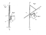
- Fig. 1 is a profile drawing of the wing of an up and over door in a closed position with the application of an element characterised by the fact it contains the electronic accelerometer that can emit signals according to its angular position.
- Fig. 2 outlines the element relative to the electronic accelerometer fixed solidly to the wing, highlighting the signal entity as a projection of the component that experiences gravity g on the reference axis.
- Fig. 3 is a representation corresponding to Fig. 1 where the wing of the door is in an intermediate position between closed and open and it establishes an angular position with respect to the vertical (different to the value of 0 degrees) which is the same angular position established by the element fixed solidly to it containing the electronic accelerometer.
- Fig. 4 also shows the element relative to the electronic accelerometer fixed solidly to the wing, showing that the projection of the component that experiences gravity g on the reference axis has changed (in diminution) compared to Fig. 2 .
- Fig. 5 is a representation corresponding to fig. 1 where the wing of the door is almost in the horizontal position of open and creates an angular position with respect to the vertical (about 90 degrees) which is the same angle established by the element fixed solidly to it containing the electronic accelerometer.
- Fig. 6 also here outlines the element relative to the electronic accelerometer fixed solidly to the wing, showing that the projection of the component that experiences gravity g on the reference axis has changed (towards 0) compared to Fig. 2 .
- Element 3 is installed in such a way that when the wing 1 is closed the x axis is parallel to the vertical position of the wing.
- the signals emitted by the electronic accelerometer relative to the x axis is determined as a function of the projection that the inertial part 4 (symbolically represented with a portion of the rod acting as a pendulum), with respect to gravity "g", effectuates on the x axis during the variation of the angular position assumed by the element 3. Because element 3 is solidly fixed to the wing 1, each signal emitted by the electronic accelerometer corresponding to each of its angular positions precisely identifies the position assumed by the wing while it is moving.
Landscapes
- Engineering & Computer Science (AREA)
- Mechanical Engineering (AREA)
- Power-Operated Mechanisms For Wings (AREA)
- Burglar Alarm Systems (AREA)
- Invalid Beds And Related Equipment (AREA)
Abstract
Description
- This patent concerns the moving parts of garage doors, also entrances to premises, like entrance frames, gates and barriers, and more generally all those parts that when moving can accidentally come into contact with people and things. It is well-known that for the above-mentioned moving parts, when moved automatically, current regulations oblige the adoption of adequate devices to ensure people or things that are near said moving parts are not harmed or damaged: among other things, such standards require that in the event of the moving part of the automated door hitting people or things, that this is limited in intensity and duration.
- On the market there are 2 approaches for limiting the forces: contact sensors and motion control.
- In both cases the idea is to limit or stop the movement, or reverse its direction.
- In this application we will not take into consideration presence sensors that prevent access to the moving part since they do protect the moving part by getting the collision signal from the same moving part. While contact sensors are generally applied to the parts most likely to hit something, and when they intervene they react immediately, motion control intervenes through the kinematic chain. Both solutions described above have their drawbacks. There are numerous problems connected to the contact sensors.
- In fact, contact sensors are not easy to apply, since they cannot cover the whole moving part that might be involved in a collision.
- For an adequate and complete coverage using contact sensors the relative costs would render protection costly to install and maintain. Moreover, they intervene with a narrow angle of impact.
- Motion control (or control over the force) on the other hand has the drawback of the response time, since the measuring of the force is carried out through the increase in the absorption of the current of the motors. This has a double disadvantage because the measuring is done upstream of the kinematic chain and because the measurement is indirect, sensing the results of a collision and not the collision itself.
- Another drawback is the need to distinguish the increase of the force due to normal factors, like for example an increase in wear and tear, from a real bump.
- The purpose of this patent is to create a device for controlling the movement of a moving part of a frame that guarantees security in a valid way, limiting the force that it might have against any obstacles in the way of people or things that it might encounter while it is moving. Another purpose of this patent is to be able to regulate the speed of the movement of the moving part in those areas where it is necessary to limit the motion in the presence of an obstacle.
- This is obtained by using a device like the one described in claim 1.
- Such a device, known also by the commercial name of an electronic accelerometer, can be similar to the one used in other applications on the market.
- To more fully highlight the attainment of the aims mentioned above, we can consider the concrete case of the wing of an up and over door moved by one of the automated methods available on the market.
- Similarly the above-mentioned device can be applied for the same purposes described above, and which will be clarified more fully in the description, also to other moving parts that have in common the requirement to control their operation following impact with people or things.
- The main shortcoming in the numerous automation variants is that of the parameters taken into consideration for the movement of the wing, where the wing does not show up directly, but only shows up as a passive element that comes into play only when effected by bumps or when it encounters an obstacle during its movement. One of the drawbacks that current automated systems on the market have is the fact that they do not recognise the positions assumed by the wing during its travel, so the control of any counter forces that might present themselves at the ends is insufficient, and indeed to stop the door one of the most common solutions adopted is the use of limit stops that interrupt the power supply to the motors that power the motion.
- Another drawback of currently available automated systems comes from the difficulty of intervening quickly to block the movement of the wing following a collision or the presence of an obstacle because this should provoke an increase in the supply of current that exceeds a threshold, which cannot be too low because it is counter to the normal functionality of the movement.
- A further drawback of currently available automated systems is due to the fact that following a power cut one or more movements have to be carried out that are not so safe because the positions assumed by the wing during its movement are unknown.
- This happens with bigger problems also in the case of the disengagement of the motors from the movable part.
- Avoiding the above-mentioned drawbacks falls within the purposes of this patent and to attain said purposes an electronic accelerometer is used as mentioned earlier.
- Said electronic accelerometer provides continuous analogue and digital signals on the basis of the angular position of said element that incorporates the electrical components that render it an electronic accelerometer.
- The above-mentioned accelerometer can be the more simple linear type, where the signals emitted (voltage) refer to two Cartesian axes x and y, and whose magnitude for each angular position are equalised to the relative trigonometric sine and cosine values.
- The element with the accelerometer is put securely on the wing, deciding for example that the x axis is parallel to the plane of the wing and when the wing is closed is in the vertical.
- For each position assumed along the path of the movement of the wing (which goes form the initial completely closed position of the wing (vertical) to the completely open position (horizontal and vice versa) the electronic accelerometer assumes its own angular position (which in the case in question is the same as that assumed by the wing) and emits a signal (voltage) that once transduced and processed becomes, together with the other movement parameters, an integral part of the automated control.
- The positions assumed by the wing during its movement, characterised by its angular positions, (taking into account that the accelerometer is solidly fixed to the wing) are clearly known because they are related to the signals emitted by the electronic accelerometer regarding its own angular positions.
- So, the normal movement of the wing is regulated as speed by processing the signals emitted by the accelerometer and at the ends of the path the movement is progressively reduced so that in the closing stage the wing stops softly in the support, and in the opening stage the absorption of the current that powers the motors is regulated with a moderate push.
- The main reason for this patent is that following a bump of the wing against an obstacle that the wing encounters while it is moving, the electronic accelerometer (fastened solidly to the wing) senses it as a variation in speed and emits a signal variation that when properly transduced and processed generates a rapid response with the stopping of the movement and with a possible inversion of the movement before an opposition force is established that is greater than a pre-set threshold.
- In particular, surmising a constant angular movement of the wing, the above-described variation corresponds to the derivative of the wing's speed of movement: in the example, such a variation is proportional to the increase (or the diminution) of the variation of the sine of the angle formed by the position of the wing with the fixed part.
- Properly analysing this latter value and its course, we can reasonably recognise the type of bump, against a non-deformable object or an supple bump and eventually consider the response to make.
- One advantage of the device is that it can be fixed in a non-parallel position to the wing in such a way as to be able to use the zone of maximum sensitivity which in the case in question is proportional to the sine of the above-mentioned angle.
- It should be made clear here that the intervention of the electronic accelerometer that controls the reaction force of the wing during its movement against an obstacle or following a collision, it can also not be limited to when said events effect the wing in the normal direction of the plane, but also when the above-mentioned events (collisions and obstacles) effect the wing in a crosswise direction.
- In this specific case, the device can distinguish the various directions of the collision described above so as to allow the appropriate distinct actions to be undertaken.
- The signal of the electronic accelerometer following a collision is used as a signal for managing the control device concerned with the collisions or bumps in a way consequent to the movement component observed, considering it a perpendicular or planar bump with respect to the frame that is moving.
- The device provides the continual verification of the presence of any jamming of the wing.
- This could be better implemented if the electronic accelerometer is positioned on opposite ends of the moving frame and the relative signals are combined to get more information and/or accuracy regarding identifying the collision and/or jamming of the wing.
- It needs to be said that more than one device can be installed with the above-mentioned characteristics, arranging them in areas of the wing considered the most critical, and in such a way that the signal is sensitive to the collisions even when there is, for example, a wing with considerable inertia.
- It should be repeated that what has been said of an up and over door, which moves along the guiderails of the fixed frame, is also valid for bar wings that are subject only to rotation (both in the vertical direction, as well as in the horizontal) or for any other part whose movement, even indirectly, is referable to a rotating component.
- It should be said, finally, that this patent covers every other solution where in the place of an electronic accelerometer an angular position sensor is used that emits signal with similar functions to those of an electronic accelerometer, like a gyroscope.
- Naturally the signal received from the electronic accelerometer following a collision of the frame can usefully be combined and/or compared with at least one other signal that has been observed like the signal regarding current absorption, vibration, noise, etc. so as to obtain a quick, precise control, so there are no false alarms.
- What has been described can be clarified by examining the attached drawings.
-
Fig. 1 is a profile drawing of the wing of an up and over door in a closed position with the application of an element characterised by the fact it contains the electronic accelerometer that can emit signals according to its angular position. -
Fig. 2 outlines the element relative to the electronic accelerometer fixed solidly to the wing, highlighting the signal entity as a projection of the component that experiences gravity g on the reference axis. -
Fig. 3 is a representation corresponding toFig. 1 where the wing of the door is in an intermediate position between closed and open and it establishes an angular position with respect to the vertical (different to the value of 0 degrees) which is the same angular position established by the element fixed solidly to it containing the electronic accelerometer. -
Fig. 4 also shows the element relative to the electronic accelerometer fixed solidly to the wing, showing that the projection of the component that experiences gravity g on the reference axis has changed (in diminution) compared toFig. 2 . -
Fig. 5 is a representation corresponding tofig. 1 where the wing of the door is almost in the horizontal position of open and creates an angular position with respect to the vertical (about 90 degrees) which is the same angle established by the element fixed solidly to it containing the electronic accelerometer. -
Fig. 6 also here outlines the element relative to the electronic accelerometer fixed solidly to the wing, showing that the projection of the component that experiences gravity g on the reference axis has changed (towards 0) compared toFig. 2 . - According to the outline shown in the diagrams it is applied to the wing 1 of an up and over door, which in its movement rotates, using its two pivots 2 along the guiderails in the fixed frame, identified in the diagram with the vertical of its K-K plane, the element A that incorporates the electronic accelerometer with the two axes x and y.
- Element 3 is installed in such a way that when the wing 1 is closed the x axis is parallel to the vertical position of the wing.
- The signals emitted by the electronic accelerometer relative to the x axis is determined as a function of the projection that the inertial part 4 (symbolically represented with a portion of the rod acting as a pendulum), with respect to gravity "g", effectuates on the x axis during the variation of the angular position assumed by the element 3. Because element 3 is solidly fixed to the wing 1, each signal emitted by the electronic accelerometer corresponding to each of its angular positions precisely identifies the position assumed by the wing while it is moving.
- In the case of the representations of the various diagrams, because the projections of the inertial part 4 are on the x axis, corresponding to the trigonometric cosine, the value of the signal with the wing 1 closed (vertical) will be 1 and with the wing open (horizontal) it will be 0.
- Following what has been said earlier, we can understand the enormous importance of the inventive capacity of this patent, which revolutionises the methodology used until now regarding safety, since the electronic accelerometer that is solidly fixed to the moving part, when said part is bumped or encounters a pre-fixed obstacle it emits a variation of the signal that when transduced and processed quickly blocks the movement and/or inverts the direction of the movement.
Claims (13)
- Device for controlling the safety of a door or window frame during its movement, characterised by the fact that an electronic accelerometer (A, G) is used that emits signals with each collision or each obstacle encountered by a frame (1) that is moving, and which includes a rotation component to which frame (1) said accelerometer (A, G) is joined.
- Device for controlling the safety of a door or window frame during its movement according to claim 1, characterised by the fact that an electronic accelerometer (A, G) is used that emits signals with each collision or each obstacle encountered by a frame (1) that moves in a straight line, whose movement is related to a rotation movement..
- Device for controlling the safety of a frame during its movement according claim 1 or 2, characterised by the fact that said moving frame (1) is the wing (1) of a loading door.
- Device for controlling the safety of a frame during its movement according to one of the preceding claims, characterised by the fact that the electronic accelerometer (A, G) is directly positioned on the moving frame (1).
- Device for controlling the safety of a frame during its movement according to one of the previous claims characterised by the fact that the signal of the electronic accelerometer (A, G) is related to the values of the current absorbed by the motors during the movement of the frame (1).
- Device for controlling the safety of a frame during its movement according to one of the previous claims characterised by the fact that the signal of the electronic accelerometer (A, G) following a collision is used as a signal for managing the control device regarding the collisions and bumps.
- Device for controlling the safety of a frame during its movement according to one of the previous claims characterised by the fact that the signal of the electronic accelerometer (A, G) following a collision is used as a signal for managing the control device regarding the collisions and bumps in a manner consequent to the moving component, considering it either a perpendicular or planar type of bump with respect to the moving frame (1).
- Device for controlling the safety of a frame during its movement according to one or more of the preceding claims, characterised by the fact that the electronic accelerometer (A, G) is positioned with the x axis in a way that is not parallel to the position of the wing in such a way that it emits the maximum value signal corresponding to the positions assumed by the wing where one wants to obtain the maximum sensitivity to the effects of the collision.
- Device for controlling the safety of a frame during its movement according to one or more of the previous claims characterised by the fact that the electronic accelerometer (A, G) is an electronic accelerometer with a linear gravimetric inertia sensor (G), with at least one axis (x, y) that emits analogical and/or digital signals.
- Device for controlling the safety of a frame during its movement according to one or more of the previous claims characterised by the fact that the signal from the electronic accelerometer (A, G) following a collision of the frame (1) is combined and/or compared with at least one other signal like the signal for current absorption, vibration, noise, etc.
- Device for controlling the safety of a frame during its movement according to one or more of the previous claims characterised by the fact that the signal from the electronic accelerometer (A, G) is replaced by a collision or bump sensor that emits analogical signals like a gyroscope.
- Device for controlling the safety of a frame during its movement according to one or more of the previous claims characterised by the fact that the electronic accelerometer (A, G) is positioned on both opposite ends of the moving frame (1) and the relative signals are combined to get more information and/or precision regarding the identification of the collision.
- Device for controlling the safety of a frame during its movement according to one or more of the previous claims characterised by the fact that the signals supplied by the electronic accelerometer (A, G) relative to the various axes (x, y) are related to the direction of the collision with respect to the moving frame(1).
Applications Claiming Priority (1)
| Application Number | Priority Date | Filing Date | Title |
|---|---|---|---|
| IT000093A ITPD20070093A1 (en) | 2007-03-15 | 2007-03-15 | DEVICE FOR CHECKING THE SECURITY OF A WINDOW DURING ITS HANDLING. |
Publications (3)
| Publication Number | Publication Date |
|---|---|
| EP1970516A2 true EP1970516A2 (en) | 2008-09-17 |
| EP1970516A3 EP1970516A3 (en) | 2013-11-20 |
| EP1970516B1 EP1970516B1 (en) | 2024-06-12 |
Family
ID=39493408
Family Applications (1)
| Application Number | Title | Priority Date | Filing Date |
|---|---|---|---|
| EP08004338.3A Active EP1970516B1 (en) | 2007-03-15 | 2008-03-10 | Device for controlling the safety of a frame during its movement |
Country Status (2)
| Country | Link |
|---|---|
| EP (1) | EP1970516B1 (en) |
| IT (1) | ITPD20070093A1 (en) |
Cited By (4)
| Publication number | Priority date | Publication date | Assignee | Title |
|---|---|---|---|---|
| EP2216478A2 (en) | 2009-02-06 | 2010-08-11 | Somfy SAS | Method for detecting the presence of an element between a threshold of an opening and one end of a motorised home-automation screen |
| EP2905408A1 (en) | 2014-02-05 | 2015-08-12 | BFT SpA | Method for detecting obstacles to be applied to a gate moving horizontally or pivoting about a vertical axis |
| US10774574B2 (en) | 2018-03-26 | 2020-09-15 | Honda Motor Co., Ltd. | Operation of vehicle power doors |
| US12221822B2 (en) | 2019-06-17 | 2025-02-11 | Assa Abloy Entrance Systems Ab | Door operation management system |
Family Cites Families (2)
| Publication number | Priority date | Publication date | Assignee | Title |
|---|---|---|---|---|
| US7070226B2 (en) * | 2001-04-26 | 2006-07-04 | Litens Automotive | Powered opening mechanism and control system |
| US7119681B2 (en) * | 2004-05-11 | 2006-10-10 | Honeywell International, Inc. | MEMS based garage door sensor |
-
2007
- 2007-03-15 IT IT000093A patent/ITPD20070093A1/en unknown
-
2008
- 2008-03-10 EP EP08004338.3A patent/EP1970516B1/en active Active
Non-Patent Citations (1)
| Title |
|---|
| None * |
Cited By (8)
| Publication number | Priority date | Publication date | Assignee | Title |
|---|---|---|---|---|
| EP2216478A2 (en) | 2009-02-06 | 2010-08-11 | Somfy SAS | Method for detecting the presence of an element between a threshold of an opening and one end of a motorised home-automation screen |
| FR2941991A1 (en) * | 2009-02-06 | 2010-08-13 | Somfy Sas | METHOD OF DETECTING THE PRESENCE OF AN ELEMENT BETWEEN A THRESHOLD OF AN OPENING AND AN END OF A MOTORIZED DOMOTIC SCREEN. |
| CN101806921A (en) * | 2009-02-06 | 2010-08-18 | Somfy两合公司 | The method that object exists between the threshold of detection door opening and the motorization door curtain end |
| JP2010180696A (en) * | 2009-02-06 | 2010-08-19 | Somfy Sas | Method for detecting existence of element between sill of opening and end of electric home automation screen |
| EP2216478A3 (en) * | 2009-02-06 | 2012-08-22 | Somfy SAS | Method for detecting the presence of an element between a threshold of an opening and one end of a motorised home-automation screen |
| EP2905408A1 (en) | 2014-02-05 | 2015-08-12 | BFT SpA | Method for detecting obstacles to be applied to a gate moving horizontally or pivoting about a vertical axis |
| US10774574B2 (en) | 2018-03-26 | 2020-09-15 | Honda Motor Co., Ltd. | Operation of vehicle power doors |
| US12221822B2 (en) | 2019-06-17 | 2025-02-11 | Assa Abloy Entrance Systems Ab | Door operation management system |
Also Published As
| Publication number | Publication date |
|---|---|
| EP1970516A3 (en) | 2013-11-20 |
| ITPD20070093A1 (en) | 2008-09-16 |
| EP1970516B1 (en) | 2024-06-12 |
Similar Documents
| Publication | Publication Date | Title |
|---|---|---|
| US8991103B2 (en) | Method and device for monitoring a drive unit, especially of a window lifter, comprising a rotating drive motor | |
| CA2416912C (en) | Vehicle closure anti-pinch assembly having a non-contact sensor | |
| JP5519514B2 (en) | How to control a vertically or horizontally moving gate to keep the gate's closing surface safe against intruders | |
| EP3963166B1 (en) | Swing door-based entrance system with automatic recognition of linkage reduction curve | |
| EP2395274B1 (en) | Dynamically adaptable safety zones | |
| US7109677B1 (en) | Motorized barrier operator system for controlling a barrier after an obstruction detection and related methods | |
| US7305290B2 (en) | Controlling device of a regulating device of a motor vehicle | |
| US7119681B2 (en) | MEMS based garage door sensor | |
| EP1970516B1 (en) | Device for controlling the safety of a frame during its movement | |
| US20180119472A1 (en) | Monitoring system | |
| EP3101444A1 (en) | Door and window contact system and method that include time of flight sensors | |
| US20190136603A1 (en) | System and method for automated motor actuation in response to a travel-limit displacement of a movable barrier | |
| US9466164B2 (en) | Monitoring and control device for a door unit | |
| US20130277437A1 (en) | Spring cycle counter | |
| DE102006030639B4 (en) | motor vehicle | |
| JP7775094B2 (en) | Door opening/closing control device | |
| CA2918129C (en) | Automatic closure system impact detection | |
| JP5740495B2 (en) | Automatic door control system | |
| JP5747067B2 (en) | Automatic door control system | |
| KR20070045073A (en) | Swing automatic door safety device using acceleration sensor | |
| US20050099150A1 (en) | Door control apparatus and method | |
| WO2026099266A1 (en) | Detecting a collision during operation of an automatic door system | |
| WO2026098929A1 (en) | Detecting a collision during operation of an automatic door system | |
| CN1948688A (en) | Building or yard closing apparatus | |
| WO2020058835A2 (en) | Automatic gate with beating leaves |
Legal Events
| Date | Code | Title | Description |
|---|---|---|---|
| PUAI | Public reference made under article 153(3) epc to a published international application that has entered the european phase |
Free format text: ORIGINAL CODE: 0009012 |
|
| AK | Designated contracting states |
Kind code of ref document: A2 Designated state(s): AT BE BG CH CY CZ DE DK EE ES FI FR GB GR HR HU IE IS IT LI LT LU LV MC MT NL NO PL PT RO SE SI SK TR |
|
| AX | Request for extension of the european patent |
Extension state: AL BA MK RS |
|
| PUAL | Search report despatched |
Free format text: ORIGINAL CODE: 0009013 |
|
| AK | Designated contracting states |
Kind code of ref document: A3 Designated state(s): AT BE BG CH CY CZ DE DK EE ES FI FR GB GR HR HU IE IS IT LI LT LU LV MC MT NL NO PL PT RO SE SI SK TR |
|
| AX | Request for extension of the european patent |
Extension state: AL BA MK RS |
|
| RIC1 | Information provided on ipc code assigned before grant |
Ipc: E05F 15/00 20060101AFI20131011BHEP Ipc: E05F 15/20 20060101ALI20131011BHEP Ipc: E05D 15/44 20060101ALN20131011BHEP |
|
| 17P | Request for examination filed |
Effective date: 20140519 |
|
| RBV | Designated contracting states (corrected) |
Designated state(s): AT BE BG CH CY CZ DE DK EE ES FI FR GB GR HR HU IE IS IT LI LT LU LV MC MT NL NO PL PT RO SE SI SK TR |
|
| AKX | Designation fees paid |
Designated state(s): AT BE BG CH CY LI |
|
| REG | Reference to a national code |
Ref country code: DE Ref legal event code: R108 |
|
| REG | Reference to a national code |
Ref country code: DE Ref legal event code: R108 Effective date: 20140723 |
|
| RBV | Designated contracting states (corrected) |
Designated state(s): AT BE BG CH CY CZ DE DK EE ES FI FR GB GR HR HU IE IS IT LI LT LU LV MC MT NL NO PL PT RO SE SI SK TR |
|
| 17Q | First examination report despatched |
Effective date: 20160617 |
|
| STAA | Information on the status of an ep patent application or granted ep patent |
Free format text: STATUS: EXAMINATION IS IN PROGRESS |
|
| GRAP | Despatch of communication of intention to grant a patent |
Free format text: ORIGINAL CODE: EPIDOSNIGR1 |
|
| STAA | Information on the status of an ep patent application or granted ep patent |
Free format text: STATUS: GRANT OF PATENT IS INTENDED |
|
| RIC1 | Information provided on ipc code assigned before grant |
Ipc: E05D 15/44 20060101ALI20240213BHEP Ipc: E05F 15/41 20150101ALI20240213BHEP Ipc: E05F 15/40 20150101ALI20240213BHEP Ipc: E05D 15/38 20060101ALI20240213BHEP Ipc: E05F 15/00 20060101AFI20240213BHEP |
|
| INTG | Intention to grant announced |
Effective date: 20240312 |
|
| GRAS | Grant fee paid |
Free format text: ORIGINAL CODE: EPIDOSNIGR3 |
|
| GRAA | (expected) grant |
Free format text: ORIGINAL CODE: 0009210 |
|
| STAA | Information on the status of an ep patent application or granted ep patent |
Free format text: STATUS: THE PATENT HAS BEEN GRANTED |
|
| AK | Designated contracting states |
Kind code of ref document: B1 Designated state(s): AT BE BG CH CY CZ DE DK EE ES FI FR GB GR HR HU IE IS IT LI LT LU LV MC MT NL NO PL PT RO SE SI SK TR |
|
| REG | Reference to a national code |
Ref country code: GB Ref legal event code: FG4D |
|
| REG | Reference to a national code |
Ref country code: CH Ref legal event code: EP |
|
| REG | Reference to a national code |
Ref country code: IE Ref legal event code: FG4D |
|
| REG | Reference to a national code |
Ref country code: DE Ref legal event code: R096 Ref document number: 602008065047 Country of ref document: DE |
|
| PG25 | Lapsed in a contracting state [announced via postgrant information from national office to epo] |
Ref country code: BG Free format text: LAPSE BECAUSE OF FAILURE TO SUBMIT A TRANSLATION OF THE DESCRIPTION OR TO PAY THE FEE WITHIN THE PRESCRIBED TIME-LIMIT Effective date: 20240612 |
|
| PG25 | Lapsed in a contracting state [announced via postgrant information from national office to epo] |
Ref country code: FI Free format text: LAPSE BECAUSE OF FAILURE TO SUBMIT A TRANSLATION OF THE DESCRIPTION OR TO PAY THE FEE WITHIN THE PRESCRIBED TIME-LIMIT Effective date: 20240612 Ref country code: HR Free format text: LAPSE BECAUSE OF FAILURE TO SUBMIT A TRANSLATION OF THE DESCRIPTION OR TO PAY THE FEE WITHIN THE PRESCRIBED TIME-LIMIT Effective date: 20240612 |
|
| REG | Reference to a national code |
Ref country code: LT Ref legal event code: MG9D |
|
| PG25 | Lapsed in a contracting state [announced via postgrant information from national office to epo] |
Ref country code: GR Free format text: LAPSE BECAUSE OF FAILURE TO SUBMIT A TRANSLATION OF THE DESCRIPTION OR TO PAY THE FEE WITHIN THE PRESCRIBED TIME-LIMIT Effective date: 20240913 |
|
| REG | Reference to a national code |
Ref country code: NL Ref legal event code: MP Effective date: 20240612 |
|
| PG25 | Lapsed in a contracting state [announced via postgrant information from national office to epo] |
Ref country code: ES Free format text: LAPSE BECAUSE OF FAILURE TO SUBMIT A TRANSLATION OF THE DESCRIPTION OR TO PAY THE FEE WITHIN THE PRESCRIBED TIME-LIMIT Effective date: 20240612 |
|
| PG25 | Lapsed in a contracting state [announced via postgrant information from national office to epo] |
Ref country code: LV Free format text: LAPSE BECAUSE OF FAILURE TO SUBMIT A TRANSLATION OF THE DESCRIPTION OR TO PAY THE FEE WITHIN THE PRESCRIBED TIME-LIMIT Effective date: 20240612 |
|
| PG25 | Lapsed in a contracting state [announced via postgrant information from national office to epo] |
Ref country code: NO Free format text: LAPSE BECAUSE OF FAILURE TO SUBMIT A TRANSLATION OF THE DESCRIPTION OR TO PAY THE FEE WITHIN THE PRESCRIBED TIME-LIMIT Effective date: 20240912 Ref country code: LV Free format text: LAPSE BECAUSE OF FAILURE TO SUBMIT A TRANSLATION OF THE DESCRIPTION OR TO PAY THE FEE WITHIN THE PRESCRIBED TIME-LIMIT Effective date: 20240612 Ref country code: HR Free format text: LAPSE BECAUSE OF FAILURE TO SUBMIT A TRANSLATION OF THE DESCRIPTION OR TO PAY THE FEE WITHIN THE PRESCRIBED TIME-LIMIT Effective date: 20240612 Ref country code: GR Free format text: LAPSE BECAUSE OF FAILURE TO SUBMIT A TRANSLATION OF THE DESCRIPTION OR TO PAY THE FEE WITHIN THE PRESCRIBED TIME-LIMIT Effective date: 20240913 Ref country code: FI Free format text: LAPSE BECAUSE OF FAILURE TO SUBMIT A TRANSLATION OF THE DESCRIPTION OR TO PAY THE FEE WITHIN THE PRESCRIBED TIME-LIMIT Effective date: 20240612 Ref country code: ES Free format text: LAPSE BECAUSE OF FAILURE TO SUBMIT A TRANSLATION OF THE DESCRIPTION OR TO PAY THE FEE WITHIN THE PRESCRIBED TIME-LIMIT Effective date: 20240612 Ref country code: BG Free format text: LAPSE BECAUSE OF FAILURE TO SUBMIT A TRANSLATION OF THE DESCRIPTION OR TO PAY THE FEE WITHIN THE PRESCRIBED TIME-LIMIT Effective date: 20240612 |
|
| PG25 | Lapsed in a contracting state [announced via postgrant information from national office to epo] |
Ref country code: NL Free format text: LAPSE BECAUSE OF FAILURE TO SUBMIT A TRANSLATION OF THE DESCRIPTION OR TO PAY THE FEE WITHIN THE PRESCRIBED TIME-LIMIT Effective date: 20240612 |
|
| REG | Reference to a national code |
Ref country code: AT Ref legal event code: MK05 Ref document number: 1694385 Country of ref document: AT Kind code of ref document: T Effective date: 20240612 |
|
| PG25 | Lapsed in a contracting state [announced via postgrant information from national office to epo] |
Ref country code: NL Free format text: LAPSE BECAUSE OF FAILURE TO SUBMIT A TRANSLATION OF THE DESCRIPTION OR TO PAY THE FEE WITHIN THE PRESCRIBED TIME-LIMIT Effective date: 20240612 |
|
| PG25 | Lapsed in a contracting state [announced via postgrant information from national office to epo] |
Ref country code: PT Free format text: LAPSE BECAUSE OF FAILURE TO SUBMIT A TRANSLATION OF THE DESCRIPTION OR TO PAY THE FEE WITHIN THE PRESCRIBED TIME-LIMIT Effective date: 20241014 |
|
| PG25 | Lapsed in a contracting state [announced via postgrant information from national office to epo] |
Ref country code: PT Free format text: LAPSE BECAUSE OF FAILURE TO SUBMIT A TRANSLATION OF THE DESCRIPTION OR TO PAY THE FEE WITHIN THE PRESCRIBED TIME-LIMIT Effective date: 20241014 |
|
| PG25 | Lapsed in a contracting state [announced via postgrant information from national office to epo] |
Ref country code: PL Free format text: LAPSE BECAUSE OF FAILURE TO SUBMIT A TRANSLATION OF THE DESCRIPTION OR TO PAY THE FEE WITHIN THE PRESCRIBED TIME-LIMIT Effective date: 20240612 |
|
| PG25 | Lapsed in a contracting state [announced via postgrant information from national office to epo] |
Ref country code: EE Free format text: LAPSE BECAUSE OF FAILURE TO SUBMIT A TRANSLATION OF THE DESCRIPTION OR TO PAY THE FEE WITHIN THE PRESCRIBED TIME-LIMIT Effective date: 20240612 |
|
| PG25 | Lapsed in a contracting state [announced via postgrant information from national office to epo] |
Ref country code: AT Free format text: LAPSE BECAUSE OF FAILURE TO SUBMIT A TRANSLATION OF THE DESCRIPTION OR TO PAY THE FEE WITHIN THE PRESCRIBED TIME-LIMIT Effective date: 20240612 Ref country code: IS Free format text: LAPSE BECAUSE OF FAILURE TO SUBMIT A TRANSLATION OF THE DESCRIPTION OR TO PAY THE FEE WITHIN THE PRESCRIBED TIME-LIMIT Effective date: 20241012 |
|
| PG25 | Lapsed in a contracting state [announced via postgrant information from national office to epo] |
Ref country code: CZ Free format text: LAPSE BECAUSE OF FAILURE TO SUBMIT A TRANSLATION OF THE DESCRIPTION OR TO PAY THE FEE WITHIN THE PRESCRIBED TIME-LIMIT Effective date: 20240612 |
|
| PG25 | Lapsed in a contracting state [announced via postgrant information from national office to epo] |
Ref country code: RO Free format text: LAPSE BECAUSE OF FAILURE TO SUBMIT A TRANSLATION OF THE DESCRIPTION OR TO PAY THE FEE WITHIN THE PRESCRIBED TIME-LIMIT Effective date: 20240612 Ref country code: SK Free format text: LAPSE BECAUSE OF FAILURE TO SUBMIT A TRANSLATION OF THE DESCRIPTION OR TO PAY THE FEE WITHIN THE PRESCRIBED TIME-LIMIT Effective date: 20240612 |
|
| PG25 | Lapsed in a contracting state [announced via postgrant information from national office to epo] |
Ref country code: SK Free format text: LAPSE BECAUSE OF FAILURE TO SUBMIT A TRANSLATION OF THE DESCRIPTION OR TO PAY THE FEE WITHIN THE PRESCRIBED TIME-LIMIT Effective date: 20240612 Ref country code: RO Free format text: LAPSE BECAUSE OF FAILURE TO SUBMIT A TRANSLATION OF THE DESCRIPTION OR TO PAY THE FEE WITHIN THE PRESCRIBED TIME-LIMIT Effective date: 20240612 Ref country code: PL Free format text: LAPSE BECAUSE OF FAILURE TO SUBMIT A TRANSLATION OF THE DESCRIPTION OR TO PAY THE FEE WITHIN THE PRESCRIBED TIME-LIMIT Effective date: 20240612 Ref country code: IS Free format text: LAPSE BECAUSE OF FAILURE TO SUBMIT A TRANSLATION OF THE DESCRIPTION OR TO PAY THE FEE WITHIN THE PRESCRIBED TIME-LIMIT Effective date: 20241012 Ref country code: EE Free format text: LAPSE BECAUSE OF FAILURE TO SUBMIT A TRANSLATION OF THE DESCRIPTION OR TO PAY THE FEE WITHIN THE PRESCRIBED TIME-LIMIT Effective date: 20240612 Ref country code: CZ Free format text: LAPSE BECAUSE OF FAILURE TO SUBMIT A TRANSLATION OF THE DESCRIPTION OR TO PAY THE FEE WITHIN THE PRESCRIBED TIME-LIMIT Effective date: 20240612 Ref country code: AT Free format text: LAPSE BECAUSE OF FAILURE TO SUBMIT A TRANSLATION OF THE DESCRIPTION OR TO PAY THE FEE WITHIN THE PRESCRIBED TIME-LIMIT Effective date: 20240612 |
|
| REG | Reference to a national code |
Ref country code: DE Ref legal event code: R097 Ref document number: 602008065047 Country of ref document: DE |
|
| PG25 | Lapsed in a contracting state [announced via postgrant information from national office to epo] |
Ref country code: DK Free format text: LAPSE BECAUSE OF FAILURE TO SUBMIT A TRANSLATION OF THE DESCRIPTION OR TO PAY THE FEE WITHIN THE PRESCRIBED TIME-LIMIT Effective date: 20240612 |
|
| PLBE | No opposition filed within time limit |
Free format text: ORIGINAL CODE: 0009261 |
|
| STAA | Information on the status of an ep patent application or granted ep patent |
Free format text: STATUS: NO OPPOSITION FILED WITHIN TIME LIMIT |
|
| 26N | No opposition filed |
Effective date: 20250313 |
|
| PG25 | Lapsed in a contracting state [announced via postgrant information from national office to epo] |
Ref country code: SE Free format text: LAPSE BECAUSE OF FAILURE TO SUBMIT A TRANSLATION OF THE DESCRIPTION OR TO PAY THE FEE WITHIN THE PRESCRIBED TIME-LIMIT Effective date: 20240612 |
|
| REG | Reference to a national code |
Ref country code: DE Ref legal event code: R119 Ref document number: 602008065047 Country of ref document: DE |
|
| PG25 | Lapsed in a contracting state [announced via postgrant information from national office to epo] |
Ref country code: MC Free format text: LAPSE BECAUSE OF FAILURE TO SUBMIT A TRANSLATION OF THE DESCRIPTION OR TO PAY THE FEE WITHIN THE PRESCRIBED TIME-LIMIT Effective date: 20240612 |
|
| REG | Reference to a national code |
Ref country code: CH Ref legal event code: H13 Free format text: ST27 STATUS EVENT CODE: U-0-0-H10-H13 (AS PROVIDED BY THE NATIONAL OFFICE) Effective date: 20251023 |
|
| PG25 | Lapsed in a contracting state [announced via postgrant information from national office to epo] |
Ref country code: LU Free format text: LAPSE BECAUSE OF NON-PAYMENT OF DUE FEES Effective date: 20250310 |
|
| GBPC | Gb: european patent ceased through non-payment of renewal fee |
Effective date: 20250310 |
|
| REG | Reference to a national code |
Ref country code: BE Ref legal event code: MM Effective date: 20250331 |
|
| PG25 | Lapsed in a contracting state [announced via postgrant information from national office to epo] |
Ref country code: DE Free format text: LAPSE BECAUSE OF NON-PAYMENT OF DUE FEES Effective date: 20251001 |
|
| PG25 | Lapsed in a contracting state [announced via postgrant information from national office to epo] |
Ref country code: GB Free format text: LAPSE BECAUSE OF NON-PAYMENT OF DUE FEES Effective date: 20250310 |
|
| PG25 | Lapsed in a contracting state [announced via postgrant information from national office to epo] |
Ref country code: FR Free format text: LAPSE BECAUSE OF NON-PAYMENT OF DUE FEES Effective date: 20250331 |
|
| PG25 | Lapsed in a contracting state [announced via postgrant information from national office to epo] |
Ref country code: BE Free format text: LAPSE BECAUSE OF NON-PAYMENT OF DUE FEES Effective date: 20250331 |
|
| PG25 | Lapsed in a contracting state [announced via postgrant information from national office to epo] |
Ref country code: CH Free format text: LAPSE BECAUSE OF NON-PAYMENT OF DUE FEES Effective date: 20250331 |
|
| PG25 | Lapsed in a contracting state [announced via postgrant information from national office to epo] |
Ref country code: IE Free format text: LAPSE BECAUSE OF NON-PAYMENT OF DUE FEES Effective date: 20250310 |
|
| PGFP | Annual fee paid to national office [announced via postgrant information from national office to epo] |
Ref country code: IT Payment date: 20260227 Year of fee payment: 19 |