EP1970433B1 - Algen-Mikroben-Photosynthese-Reaktionssystem und Verfahren dafür - Google Patents
Algen-Mikroben-Photosynthese-Reaktionssystem und Verfahren dafür Download PDFInfo
- Publication number
- EP1970433B1 EP1970433B1 EP08152764.0A EP08152764A EP1970433B1 EP 1970433 B1 EP1970433 B1 EP 1970433B1 EP 08152764 A EP08152764 A EP 08152764A EP 1970433 B1 EP1970433 B1 EP 1970433B1
- Authority
- EP
- European Patent Office
- Prior art keywords
- unit
- pipe
- nutrient solution
- liquid
- oxygen
- Prior art date
- Legal status (The legal status is an assumption and is not a legal conclusion. Google has not performed a legal analysis and makes no representation as to the accuracy of the status listed.)
- Ceased
Links
- 241000195493 Cryptophyta Species 0.000 title claims description 95
- 230000029553 photosynthesis Effects 0.000 title claims description 74
- 238000010672 photosynthesis Methods 0.000 title claims description 74
- 238000006243 chemical reaction Methods 0.000 title claims description 58
- 238000000034 method Methods 0.000 title claims description 15
- 239000007788 liquid Substances 0.000 claims description 127
- QVGXLLKOCUKJST-UHFFFAOYSA-N atomic oxygen Chemical compound [O] QVGXLLKOCUKJST-UHFFFAOYSA-N 0.000 claims description 117
- 229910052760 oxygen Inorganic materials 0.000 claims description 117
- 239000001301 oxygen Substances 0.000 claims description 117
- 235000015097 nutrients Nutrition 0.000 claims description 111
- 239000013589 supplement Substances 0.000 claims description 13
- XLYOFNOQVPJJNP-UHFFFAOYSA-N water Substances O XLYOFNOQVPJJNP-UHFFFAOYSA-N 0.000 claims description 13
- 238000009987 spinning Methods 0.000 claims description 10
- 239000007921 spray Substances 0.000 claims description 2
- 230000000149 penetrating effect Effects 0.000 claims 1
- 240000002900 Arthrospira platensis Species 0.000 description 9
- 235000016425 Arthrospira platensis Nutrition 0.000 description 9
- 229940082787 spirulina Drugs 0.000 description 9
- 241000168517 Haematococcus lacustris Species 0.000 description 6
- 230000004308 accommodation Effects 0.000 description 6
- 238000004519 manufacturing process Methods 0.000 description 5
- 230000000243 photosynthetic effect Effects 0.000 description 5
- 210000003495 flagella Anatomy 0.000 description 4
- 239000000463 material Substances 0.000 description 4
- 238000009423 ventilation Methods 0.000 description 4
- 230000002411 adverse Effects 0.000 description 3
- 230000003247 decreasing effect Effects 0.000 description 3
- 230000003203 everyday effect Effects 0.000 description 3
- 239000011521 glass Substances 0.000 description 3
- 238000012423 maintenance Methods 0.000 description 3
- 229910001220 stainless steel Inorganic materials 0.000 description 3
- 239000010935 stainless steel Substances 0.000 description 3
- 239000012780 transparent material Substances 0.000 description 3
- 230000008901 benefit Effects 0.000 description 2
- 238000004140 cleaning Methods 0.000 description 2
- 230000000694 effects Effects 0.000 description 2
- 230000002349 favourable effect Effects 0.000 description 2
- 230000012010 growth Effects 0.000 description 2
- 241001495180 Arthrospira Species 0.000 description 1
- JEBFVOLFMLUKLF-IFPLVEIFSA-N Astaxanthin Natural products CC(=C/C=C/C(=C/C=C/C1=C(C)C(=O)C(O)CC1(C)C)/C)C=CC=C(/C)C=CC=C(/C)C=CC2=C(C)C(=O)C(O)CC2(C)C JEBFVOLFMLUKLF-IFPLVEIFSA-N 0.000 description 1
- 241000192700 Cyanobacteria Species 0.000 description 1
- 102000004190 Enzymes Human genes 0.000 description 1
- 108090000790 Enzymes Proteins 0.000 description 1
- NIXOWILDQLNWCW-UHFFFAOYSA-N acrylic acid group Chemical group C(C=C)(=O)O NIXOWILDQLNWCW-UHFFFAOYSA-N 0.000 description 1
- 230000009471 action Effects 0.000 description 1
- 230000005791 algae growth Effects 0.000 description 1
- 239000003963 antioxidant agent Substances 0.000 description 1
- 235000006708 antioxidants Nutrition 0.000 description 1
- 235000013793 astaxanthin Nutrition 0.000 description 1
- MQZIGYBFDRPAKN-ZWAPEEGVSA-N astaxanthin Chemical compound C([C@H](O)C(=O)C=1C)C(C)(C)C=1/C=C/C(/C)=C/C=C/C(/C)=C/C=C/C=C(C)C=CC=C(C)C=CC1=C(C)C(=O)[C@@H](O)CC1(C)C MQZIGYBFDRPAKN-ZWAPEEGVSA-N 0.000 description 1
- 229940022405 astaxanthin Drugs 0.000 description 1
- 239000001168 astaxanthin Substances 0.000 description 1
- 230000005587 bubbling Effects 0.000 description 1
- 210000004027 cell Anatomy 0.000 description 1
- 238000013461 design Methods 0.000 description 1
- 230000002542 deteriorative effect Effects 0.000 description 1
- 238000003306 harvesting Methods 0.000 description 1
- 235000013402 health food Nutrition 0.000 description 1
- 239000004615 ingredient Substances 0.000 description 1
- 229910052500 inorganic mineral Inorganic materials 0.000 description 1
- 239000011707 mineral Substances 0.000 description 1
- 238000012986 modification Methods 0.000 description 1
- 230000004048 modification Effects 0.000 description 1
- 235000016709 nutrition Nutrition 0.000 description 1
- 230000035764 nutrition Effects 0.000 description 1
- 235000008935 nutritious Nutrition 0.000 description 1
- 230000035479 physiological effects, processes and functions Effects 0.000 description 1
- 230000002265 prevention Effects 0.000 description 1
- 230000008569 process Effects 0.000 description 1
- 102000004169 proteins and genes Human genes 0.000 description 1
- 108090000623 proteins and genes Proteins 0.000 description 1
- 239000011555 saturated liquid Substances 0.000 description 1
- 238000012360 testing method Methods 0.000 description 1
- 235000013343 vitamin Nutrition 0.000 description 1
- 229940088594 vitamin Drugs 0.000 description 1
- 229930003231 vitamin Natural products 0.000 description 1
- 239000011782 vitamin Substances 0.000 description 1
Images


Classifications
-
- C—CHEMISTRY; METALLURGY
- C12—BIOCHEMISTRY; BEER; SPIRITS; WINE; VINEGAR; MICROBIOLOGY; ENZYMOLOGY; MUTATION OR GENETIC ENGINEERING
- C12M—APPARATUS FOR ENZYMOLOGY OR MICROBIOLOGY; APPARATUS FOR CULTURING MICROORGANISMS FOR PRODUCING BIOMASS, FOR GROWING CELLS OR FOR OBTAINING FERMENTATION OR METABOLIC PRODUCTS, i.e. BIOREACTORS OR FERMENTERS
- C12M31/00—Means for providing, directing, scattering or concentrating light
- C12M31/10—Means for providing, directing, scattering or concentrating light by light emitting elements located inside the reactor, e.g. LED or OLED
-
- C—CHEMISTRY; METALLURGY
- C12—BIOCHEMISTRY; BEER; SPIRITS; WINE; VINEGAR; MICROBIOLOGY; ENZYMOLOGY; MUTATION OR GENETIC ENGINEERING
- C12M—APPARATUS FOR ENZYMOLOGY OR MICROBIOLOGY; APPARATUS FOR CULTURING MICROORGANISMS FOR PRODUCING BIOMASS, FOR GROWING CELLS OR FOR OBTAINING FERMENTATION OR METABOLIC PRODUCTS, i.e. BIOREACTORS OR FERMENTERS
- C12M21/00—Bioreactors or fermenters specially adapted for specific uses
- C12M21/02—Photobioreactors
-
- C—CHEMISTRY; METALLURGY
- C12—BIOCHEMISTRY; BEER; SPIRITS; WINE; VINEGAR; MICROBIOLOGY; ENZYMOLOGY; MUTATION OR GENETIC ENGINEERING
- C12M—APPARATUS FOR ENZYMOLOGY OR MICROBIOLOGY; APPARATUS FOR CULTURING MICROORGANISMS FOR PRODUCING BIOMASS, FOR GROWING CELLS OR FOR OBTAINING FERMENTATION OR METABOLIC PRODUCTS, i.e. BIOREACTORS OR FERMENTERS
- C12M23/00—Constructional details, e.g. recesses, hinges
- C12M23/02—Form or structure of the vessel
- C12M23/06—Tubular
-
- C—CHEMISTRY; METALLURGY
- C12—BIOCHEMISTRY; BEER; SPIRITS; WINE; VINEGAR; MICROBIOLOGY; ENZYMOLOGY; MUTATION OR GENETIC ENGINEERING
- C12M—APPARATUS FOR ENZYMOLOGY OR MICROBIOLOGY; APPARATUS FOR CULTURING MICROORGANISMS FOR PRODUCING BIOMASS, FOR GROWING CELLS OR FOR OBTAINING FERMENTATION OR METABOLIC PRODUCTS, i.e. BIOREACTORS OR FERMENTERS
- C12M23/00—Constructional details, e.g. recesses, hinges
- C12M23/44—Multiple separable units; Modules
-
- C—CHEMISTRY; METALLURGY
- C12—BIOCHEMISTRY; BEER; SPIRITS; WINE; VINEGAR; MICROBIOLOGY; ENZYMOLOGY; MUTATION OR GENETIC ENGINEERING
- C12M—APPARATUS FOR ENZYMOLOGY OR MICROBIOLOGY; APPARATUS FOR CULTURING MICROORGANISMS FOR PRODUCING BIOMASS, FOR GROWING CELLS OR FOR OBTAINING FERMENTATION OR METABOLIC PRODUCTS, i.e. BIOREACTORS OR FERMENTERS
- C12M29/00—Means for introduction, extraction or recirculation of materials, e.g. pumps
- C12M29/20—Degassing; Venting; Bubble traps
- C12M29/22—Oxygen discharge
-
- C—CHEMISTRY; METALLURGY
- C12—BIOCHEMISTRY; BEER; SPIRITS; WINE; VINEGAR; MICROBIOLOGY; ENZYMOLOGY; MUTATION OR GENETIC ENGINEERING
- C12M—APPARATUS FOR ENZYMOLOGY OR MICROBIOLOGY; APPARATUS FOR CULTURING MICROORGANISMS FOR PRODUCING BIOMASS, FOR GROWING CELLS OR FOR OBTAINING FERMENTATION OR METABOLIC PRODUCTS, i.e. BIOREACTORS OR FERMENTERS
- C12M41/00—Means for regulation, monitoring, measurement or control, e.g. flow regulation
- C12M41/12—Means for regulation, monitoring, measurement or control, e.g. flow regulation of temperature
Definitions
- the invention generally relates to a photosynthesis reaction system and method and particularly to an algae microbe photosynthesis reaction system and method thereof.
- Spirulina algae's nutrient solution is used by photosynthesis reaction system which supplies the required nutrition for algae cells to grow and ventilates oxygen generated within the nutrient solution so that Spirulina algae can be cultivated in mass.
- a conventional photosynthesis reaction system for Spirulina is performed in an air-exposed culture pool.
- the nutrient solution of Spirulina is placed into the exposed pool for photosynthesis.
- the pool requires a large area and consumes a lot of energy.
- the weather can be a restricting factor.
- the obtained algae are also easily polluted, deteriorating its quality.
- Another conventional photosynthesis reaction system such as disclosed in CN Patent NO 95219504.6 , is a photosynthetic reaction system for spirulina, comprising a photosynthetic reaction unit and a vertical dual-spiral pipe.
- the photosynthetic reaction unit and the vertical dual-spiral pipe are transparent for the photosynthesis of the nutrient solution therein.
- the photosynthetic reaction unit has a bubbling plate and a thermal exchanger to ventilate oxygen generated in the nutrient solution and controls the temperature of the nutrient solution.
- the reaction system aims at providing a closed circulation environment to overcome shortages of large culture pool.
- WO 96/23865 describes another process for cultivating microalgae in a closed circuit.
- An object of the invention is to provide a method and a system for photosynthesis reaction of algae microbe with reduced use in area, reduced energy requirement, no restrain from everyday weather, and prevention from pollution in order to maintain the quality of algae obtained, and further more ensures the ventilation of oxygen generated by the algae and the accurate control of the temperature and light intensity of the nutrient solution, so that algae can be cultivated quickly in mass with lower cost.
- the method of the invention comprises (a) providing a photosynthesis reaction unit, comprising a transparent piping, a communicating unit (communicating in the present invention strictly means connecting, and should not be confused with telecommunication), a collecting valve, a pressured liquid transport unit with a transport pipe, an oxygen jet device with a liquid inlet, and a connecting pipe; and (b) injecting an algae and microbe nutrient solution into the transparent piping, circulating the nutrient solution within the transparent piping for photosynthesis to generate oxygen, wherein the nutrient solution flows to the communicating unit, the collecting valve, and the pressured liquid transport unit; (c) determining an included angle on a horizontal cross-sectional surface of the oxygen jet device between an axial line of the transport pipe and a normal line passing through a central point of the oxygen jet device, wherein the included angle is adjustable according to different kinds of algae; (d) opening the pressured liquid transport unit to force the nutrient solution flow toward the oxygen jet device from the transport pipe, wherein the nutrient
- Another aspect of the invention is to provide a system for photosynthesis reaction of algae microbe which comprises a photosynthesis reaction unit, which is a transparent piping; a communicating unit, connected to an exit of the transparent piping; a collecting valve, connected to an exit of the communicating unit; a pressured liquid transport unit, an entrance of which is connected to the collecting valve, and the pressured liquid transport unit has a transport pipe; an oxygen jet device, being a hollow pipe and comprising the oxygen ventilating column and a liquid collector at a lower end thereof, the oxygen ventilating column having a liquid inlet, an upper ventilator, and a pipe wall, the exit of the transport pipe communicating with the liquid inlet, wherein the exit of the transport pipe being connected to the liquid inlet along an included angle defined on a horizontal cross-sectional surface of the oxygen jet device between an axial line of the transport pipe and a normal line passing through a central point of the oxygen jet device, wherein the included angle is adjustable according to different kinds of algae, the upper ventilator being located at a top of the oxygen ventilating column,
- the enclosed branched configuration formed by the photosynthesis reaction unit, the communicating unit, the collecting valve, the pressured liquid transport unit, the transport pipe, the oxygen jet device and the connecting pipe allow the enclosed nutrient solution to circulate vertically therein for photosynthesis and oxygen ventilation. Its unique features such as small use of area, reduced energy requirement and no restrain from everyday weather greatly increases the algae yield and quality because the mostly enclosed algae can be protected from pollutions. Furthermore, light supplement unit can be added to one or both sides of the transparent piping for proper temperature and light intensity adjustment.
- the arrangement of the liquid inlet, the upper ventilator and the pipe wall makes the oxygen the oxygen formed in the nutrient solution easy to ventilate, thereby increasing the yield and is favorable for mass production.
- a temperature controlling unit is further mounted between the transparent piping and the pressured liquid transport unit to control the temperature within in the proper range for algae cultivation.
- a switch valve is mounted between the connecting piping and the liquid collector to drain out the nutrient solution when cleaning or to collect a nutrient solution sample.
- an algae microbe photosynthesis reaction system and method thereof are used to cultivate algae such as Spirulina or Haematococcus Pluvialis Flotow.
- the method comprises the following steps.
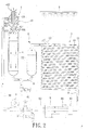
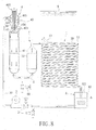
- Step (a) provides a photosynthesis reaction unit 1 which comprises a transparent piping made of transparent material such as glass, a communicating unit A, a collecting valve 2, a pressured liquid transport unit 3 having a transport pipe 30, an oxygen jet device 4 having a liquid inlet 401, and a connecting pipe 5.
- the transparent piping i.e. photosynthesis reaction unit 1
- the communicating unit A, the collecting valve 2, the pressured liquid transport unit 3, the oxygen jet device 4 and the connecting pipe 5 are connected to one another to form the algae microbe photosynthesis system according to the invention.
- Step (b) nutrient solution and algae seed are injected into the transparent piping.
- the nutrient solution flows through the transparent piping for photosynthesis to generate oxygen.
- the nutrient solution flows toward the communicating unit A and then flows to the collecting valve 2 and the pressured liquid transport unit 3.
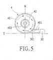
- an included angle on a horizontal cross-sectional surface of the oxygen jet device 4 between an axial line of the transport pipe 30 and a normal line N passing through a central point of the oxygen jet device 4 is determined, wherein the included angle is adjustable according to different kinds of algae.
- the transparent piping is a spiral transparent piping. Therefore, the nutrient solution flows up and down to circulate within the transparent piping so that the algae microbe absorbs sufficient light for photosynthesis for quick growth.
- the pressured liquid transport unit 3 is opened to force the nutrient solution to flow toward the oxygen jet device 4 from the transport pipe 30.
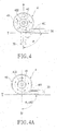
- the nutrient solution flows into the oxygen jet device 4 from the transport pipe 30 via the liquid inlet 401 along the included angle and caused a shear force on the algae, as shown in FIG. 4 .
- the nutrient solution is splashed into the oxygen jet device 4 to form a spinning splash by which the oxygen is ventilated, wherein the shear force is reduced when the included angle is smaller.
- the nutrient solution is splashed into an oxygen ventilating column 40 to form the spinning splash which is then ventilated through an upper ventilator 402.
- the nutrient solution drops to be collected by a neck 404 and then go on to hit an extension 421 of an exhaust 42 to form another splash so that oxygen is exhausted from a side ventilator 405. Finally, the nutrient solution drops to be collected inside a liquid collector 41 so that oxygen can be ventilated out from a top of the exhaust 42. Thereby, most of oxygen in the nutrient solution is ventilated out from the nutrient solution for further photosynthesis of algae microbe.
- Step (e) the nutrient solution is collected in the oxygen jet device 4 and the connecting pipe 5.
- Step (f) the nutrient solution flows into the transparent piping for further photosynthesis.
- the nutrient solution is collected in the liquid collector 41 and flows into the connecting piping 5 via a connector 6 for further photosynthesis reaction.
- the higher liquid level of the nutrient solution collected by the liquid collecting column 41 as compared to an upper layer in the transparent piping of the photosynthesis reaction unit 1, creates a potential drop to generate the pressure so that the algae nutrient solution automatically flows into the transparent piping via the connecting pipe 5.
- Step (g) after the nutrient solution flows through the transparent piping and the communicating unit A, the nutrient solution is taken from the collecting valve 2.
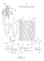
- a temperature controlling unit 8 is provided in a manner such that the nutrient solution flows toward the collecting valve 2 and the pressured liquid transport unit 3 after flowing through the communicating unit A and the temperature controlling unit 8. Thereby, the temperature of the nutrient solution can be controlled.
- a water sprayer 9 is used for Step (b) and Step (g).
- the water sprayer 9 sprays water over the transparent piping as needed to reduce the temperature of the nutrient solution inside the transparent piping.
- a light supplement unit B is further provided for Step (b) and Step (g) as shown in FIG. 6 .
- the light supplement unit B can be properly adjusted for the light intensity or the light source needed for the nutrient solution in the transparent piping.
- the photo synthesis unit 1 comprises a plurality of straight pipes 10 and a plurality of bent pipes 11.
- the straight pipes 10 and the bent pipes 11 are arranged in series in turns to form a dual-row tilt spiral transparent piping.
- An auxiliary opening 12 is formed at an upper most part of the transparent piping.
- the communicating unit A is connected to an exit of the transparent piping.
- the communicating unit A can be a connecting pipe which connects an exit of the transparent piping to an entrance of the pressured liquid transport unit 3 in order to allow the nutrient solution to directly flows into the pressured liquid transport unit 3.
- the communicating unit A comprises a liquid collecting sink A1 having an upward opening A11 and a liquid flowing pipe A2.
- the shape of the liquid collecting sink A1 is not specifically limited, and the liquid collecting sink A1 is made of the transparent material or opaque material.
- the liquid collecting sink A1 corresponds to an exit of the transparent piping for collecting the nutrient solution.
- the liquid flowing pipe A2 communicates with the liquid collecting sink A1 and an entrance of the collecting valve 2 so that the collected nutrient solution flows towards the pressure liquid transport unit 3.
- An opening A11 of the liquid collecting sink A1 can be covered by a transparent element to prevent any dusts from being dropping into the nutrient solution.
- the liquid collecting sink A1 is placed into a conservatory for preventing any dusts.
- the collecting valve 2 communicates with the exit of the communicating unit A for collecting the nutrient solution flowing within the transparent piping.
- the pressured liquid transport unit 3 is a pressured liquid pump whose entrance communicates with the collecting valve 2.
- the pressured liquid transport unit 2 has a transport pipe 30.
- the oxygen jet device 4 is a hollow pipe comprising the oxygen ventilating column 40 and a liquid collector 41.
- the oxygen ventilating column 40 is made of stainless steel.
- the liquid collector 41 is made of transparent glass or acrylic, or an opaque material such as stainless steel.
- the transport pipe 30 communicates with the liquid inlet 40.
- the upper ventilator 402 is located at the top of the oxygen ventilating column 40.
- the pipe wall 403 extends downward from the upper ventilator 402 opposite to an interior of the liquid inlet n401.
- the oxygen jet device 4 has a normal line N and a tangent line T intersecting the normal line N.
- the exit of the transport pipe 30 communicates with the liquid inlet 401 along an angle ⁇ between the tangent line T and the normal line N.
- the angle ⁇ can be 0-90 degrees.
- the angle ⁇ of the transport pipe 30 is in the range of 90-10 relative to the tangent line T.
- the oxygen ventilating column 40 has a neck 404 and a side ventilator 405 at its middle section.
- the side ventilator 405 is located under the neck 404.
- the oxygen ventilating device 4 further comprises the exhaust 42 assembled inside the oxygen ventilating column 40.
- An upper end of the exhaust 42 penetrates through the pipe wall 403.
- a lower end of the exhaust 42 has the extension 421 opposite to the interior of the side ventilator 405.
- the extension 421 can be formed, with any shape, depending on requirements of algae species.
- the connecting pipe 5 is a close pipe which can be an extending pipe 52. An end of the connecting pipe 5 connects to the photosynthesis reaction unit 1. The entrance of the transparent piping is bent downward to connect to the other end of the connecting pipe5.
- the algae photosynthesis system further comprises a connector 6 connecting a bottom of the liquid collector 41 to a bottom of the connecting pipe 5.
- the connector 6 further has a switch valve 60.
- the algae microbe photosynthesis system When the algae microbe photosynthesis system according to the invention is used, the algae microbe algae seeds and algae microbe nutrient solution are poured into the auxiliary opening 12 of the transparent piping. The nutrient solution and the algae microbe flow through the transparent piping to conduct the photosynthesis which generates oxygen. The nutrient solution flows to the communicating unit A, and then flows to the collecting valve 2 and the pressured liquid transport unit 3. The pressured liquid transport unit 3 forces the nutrient solution to flow to the oxygen jet device 4 from the communicating unit A.
- the nutrient solution is jetted into the oxygen ventilating column 40 via the liquid inlet 401 along the angle ⁇ between the exit of the transport pipe 30 and the liquid inlet 401 of the oxygen ventilating column 40.
- the nutrient solution strikes into the oxygen ventilating column 40 via the liquid inlet 401, the nutrient solution hits the oxygen ventilating column 40 of the oxygen jet device 4 to form a spinning splash by which the oxygen is ventilated through the upper ventilator 402.
- the nutrient solution drops to be collected to the neck 404 and then goes to hit an extension 421 of an exhaust 42 to form another splash so that oxygen is exhausted through the side ventilator 405.
- the nutrient solution drops to be collected inside a liquid collector 41 so that oxygen can be ventilated out from a top of the exhaust 42.
- oxygen ventilating column 40 can be made of opaque material such as stainless steel.
- the liquid collector 41 can be made of transparent material such as glass for further photosynthesis, or made of opaque material.
- the exit of the transport pipe 30 is connected to the liquid inlet 401 along the angle ⁇ as mentioned above.
- the transport pipe 30 is designed according to the requirement for different algae.
- the splash formed by jetting forms a shear force.
- Unduly large shear force adversely affects the cultivation of the algae or result in the death of the algae.
- the exit of the transport pipe 30 can be connected to the liquid inlet 401 along a particular angle so as to adjust the shear force formed when the nutrient solution is injected into the oxygen ventilating column 40.
- the angle can vary based on the requirements for algae.
- the angle ⁇ 1 can be 90 degrees as shown in FIG. 4A
- the angle ⁇ 2 can be 45 degrees as shown in FIG. 4B
- the angle ⁇ 3 can be 0 degree as shown in FIG. 4C .
- the exit of the transport pipe 30 is connected to liquid inlet 401 along the direction parallel to the tangent line T.
- the algae are Haematococcus Pluvialis Flotow, which has flagellum, unduly large shear force will cut off the flagellum and adversely affect the growth of the algae or make the growing algae die.
- the exit of the transport pipe 30 can be adjusted with the angle less than 90n degrees, i.e., the exit of the transport pipe 30 being not parallel to the tangent line T.
- the shear force is reduced to prevent the flagellum of Haematococcus Pluvialis Flotow from being broken.
- the switch valve 60 may temporarily opened to clean up heavier deposits, sample the nutrient solution for testing, or act as a harvest opening.
- the higher liquid level of the nutrient solution collected by the liquid collecting column 41 as compared with an upper layer in the transparent piping of the photosynthesis reaction unit 1, creates a potential drop to generate the pressure so that the algae nutrient solution automatically flows into the transparent piping via the connecting pipe 5, and then the nutrient solution flows into the pressured liquid transport unit 3.
- the nutrient solution can be circulated within the for algae microbe photosynthesis according to the invention to cultivate the algae microbe.
- the collecting valve 2 is opened to collect or the switch valve 60 is opened to collect.
- the nutrient solution flows into the connecting piping 5 via the connector 6. Since the connecting piping 5 has the extension pipe 52, the flowing speed of the nutrient solution slows down in the extension pipe 52. By this way, the nutrient solution stays in the connecting piping 5 for a period of time which is long enough for physiological accommodation of the algae. Any damage which might be caused by the pressured liquid transport unit 3 and the oxygen jet device 4 can therefore be eliminated, which contributes to optimal physiological status for the algae and therefore algae of increased quality.
- the exit of the liquid transport pipe 30 further has gradually reduced diameter to form a shrinking mouth 301.
- the nutrient solution flows to the shrinking mouth 301 from the pressured liquid transport unit 3 under pressure, the nutrient solution is jetted higher to get into the oxygen ventilating column 40.
- the nutrient solution hits the pipe wall 403, most oxygen can be ventilated without waiting for the spinning splash to drop. Therefore, the performance of ventilating oxygen improves.
- this embodiment is not suitable to culture the Haematococcus Pluvialis Flotow due to possible breakage of flagellum.
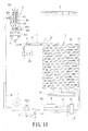
- a temperature controlling unit 8, a water sprayer 9 and at least one light supplement unit B can be further comprised in the system of the invention, as shown in FIG. 7 .
- the temperature controlling unit 8 is provided with a plurality of temperature increasing and decreasing tubes 80, an inlet adapter 81 and an exit adapter 82.
- the temperature increasing and decreasing tubes are respectively connected to an exit of the communicating unit A and an inlet of the pressured liquid transport unit 3.
- the temperature controlling unit 8 heats the water within the temperature controlling unit 8 either by manually operating or automatic control.
- the thermal energy of water is transferred to the temperature increasing and decreasing tubes 80 for controlling the temperature of the nutrient solution.
- cold water is poured into the temperature controlling unit 8 to reduce the temperature of the nutrient solution.
- the location of the temperature controlling unit 8 is not limited between the collecting valve 2 and the communicating unit A.
- the communicating unit 8 can be located at other places as long as the purpose of controlling temperature is achieved.
- the water sprayer 9 is located upon the photosynthesis reaction unit 1, and is operated either by manually operating or automatic control to reduce the temperature of the nutrient solution within the transparent piping.
- the light supplement unit B can be a fluorescent lamp or LED, for example.
- the number of the light supplement unit B may vary as needed.
- the light supplement unit B can be located on any side, such as upper side or lower side, of the transparent piping.
- the light supplement unit B is located on the lower side of the transparent piping, the light source of the light supplement unit B can be white light, red light or blue light.
- the connecting pipe 5 of the algae microbe photosynthesis reaction system has a straight pipe 53.
- One end of the connecting pipe 5 is connected to the photosynthesis reaction unit I, and the other end of the connecting pipe 5 is connected to the liquid collector 41.
- the algae microbe flows into the photosynthesis reaction unit 1 via the straight pipe 53 of the connecting pipe 5 to circulate for culture.
- the connecting pipe 5 is to adjust the physiological accommodation of the algae microbe in the connecting pipe 5.
- the connecting pipe 5 with the straight pipe 53 allows the algae microbe to quickly flow into the transparent piping for circulation.
- the connecting pipe 5 with the extension tube 52 is needed to slow down the flow of the algae microbe in the connecting pipe 5 so that the algae microbe has enough time to accommodate their physiology.
- the pipe wall 403 reaches the location above the liquid inlet 401, i.e., corresponds to the liquid inlet 401.
- the nutrient solution is injected into the oxygen ventilating column 40 via the liquid inlet 401 of the oxygen jet device 4 and hits the exhaust 42, part of oxygen is ventilated without waiting the spinning splash to drop, thereby increasing the amount of the oxygen ventilated.
- a few of the nutrient solution might sputters out of the upper ventilator 402 due to the splashing of the nutrient solution against the upper ventilator 402.
- the location of the temperature controlling unit 8 may vary.
- the temperature controlling unit 8 may be located inside the liquid collecting sink A1 for controlling the temperature of the nutrient solution, or the temperature controlling unit may also be located in other places more appropriate than the liquid collecting sink A1.
- the temperature controlling unit 8 can be arranged between the exit of the transparent piping and the entrance of the pressured liquid transport unit 3 to achieve the purpose of controlling the temperature of the nutrient solution.
- the liquid inlet 401 is located at a lower section of the oxygen ventilating column 40 and above the extension 421.
- the time to generate spinning splash from the nutrient solution is reduced so that the nutrient solution directly drops to the extension 421 and then into the liquid collector 41.
- the embodiment as shown in FIG. 10 illustrates the speed-up culture for specific algae which need not no physiological accommodation.
- the liquid collector 41 of the oxygen jet device 4 faces the oxygen ventilating column 40 and has its lower section shortened upward.
- the connecting pipe 5 is a horizontal tube 54 connecting the liquid collector 41 to the transparent piping so that the nutrient solution need not have any physiological accommodation allowance for the algae and the solution would quickly flow into the transparent piping.
- the system of the invention further comprises an adjustment column C1 and a joint C2.
- a bottom of the adjustment column C1 is connected to the exit of the collecting valve 2.
- the joint C 2 connects a top of the adjustment column C1 to the entrance of the pressured liquid transport unit 3.
- the pressured liquid transport unit 3 may open to force the nutrient solution into the oxygen jet device 4 by its suction action.
- the liquid collector 41 has a smaller diameter at its upper part so that the nutrient solution flows into the adjustment column C1 at slower speed.
- the suction of the pressured liquid transport unit 3 reduces the possibility of deposit onto the walls and accelerates the flow of the nutrient solution into the photosynthesis reaction unit 1 after the liquid collector 41. Thereby, the circulation can be speed up and thus the yield increases. Is this case, some elements such as the adjustment column C1 and the joint C2 etc and extra space are needed.
- the increase in production cost can be covered by increased yield which is obtained by reducing the sticking of particular algae on the walls. Therefore, the addition of the extra elements and space would not be a disadvantage in terms of total profit, considering its benefit.
- this invention also provides a system for photosynthesis reaction of algae microbe, comprising: a photosynthesis reaction unit 1, which is a transparent piping; a communicating unit A, connected to an exit of the transparent piping; a collecting valve 2, connected to an exit of the communicating unit A; a pressured liquid transport unit 3, an entrance of which is connected to the collecting valve 2, and the pressured liquid transport unit 3 has a transport pipe 30; an oxygen jet device 4, being a hollow pipe and comprising the oxygen ventilating column 40 and a liquid collector 41 at a lower end thereof, the oxygen ventilating column 40 having a liquid inlet 401, an upper ventilator 402, and a pipe wall 403, the exit of the transport pipe 30 communicating with the liquid inlet 401, wherein the exit of the transport pipe 30 being connected to the liquid inlet 401 along an included angle defined on a horizontal cross-sectional surface of the oxygen jet device 4 between an axial line of the transport pipe 30 and
- the included angle above is adjustable according to different kinds of algae.
- the upper ventilator 402 can be located at a top of the oxygen ventilating column 40, and the pipe wall 403 extends downward from the upper ventilator 402.
- the system also includes a connecting pipe 5, which is a close pipe.
- the connecting pipe 5 can be used to connect the liquid collector 41 to the photosynthesis reaction unit 1.
- an enclosed multi-piping configuration formed by the photosynthesis reaction unit 1, the communicating unit A, the collecting valve 2, the pressured liquid transport unit 3, the transport pipe 30, the oxygen jet device 4 and the connecting pipe 5 allow the enclosed nutrient solution to circulate therein for photosynthesis and oxygen ventilation. Its unique features such as small use of area, reduced energy requirement and no restrain from everyday weather greatly increases the algae yield and quality because the enclosed algae can be protected from pollutions especially when in the liquid collecting sink A1 of the communicating unit A. Additionally, the system of the invention can also be used in a partially enclosed environment.
- the entrance of the transport pipe 30 is connected to the liquid inlet 401 along the angle ⁇ between the normal line N and the tangent line T of the oxygen jet device 4.
- the angle ⁇ may vary as needed for different algae in order to prevent any unduly large shear force formed by spinning splash due to the injecting of the nutrient solution.
- the arrangement of the liquid inlet 401, the upper ventilator 402 and the pipe wall 403, also the arrangement of the exhaust 42 and the extension 421 make the oxygen formed in the nutrient solution easy to ventilate, thereby increasing the yield and is favorable for mass production.
- the assembly of the oxygen ventilating column 40 and the liquid collector 41 to form the oxygen jet device 4 is easy and strong, and therefore has lower cost in terms of assembling and maintenance.
- the assembly of the oxygen column 40 and the liquid collector 41, and the design of the transparent piping are easy for cleaning and maintenance so as to ensure the effect of photosynthesis and quality of algae.
- the arrangement of the temperature controlling unit 8, the water sprayer 9 and the light supplement unit B allows proper temperature adjustment and light intensity for the nutrient solution according to geography, seasons and weathers.
Landscapes
- Health & Medical Sciences (AREA)
- Life Sciences & Earth Sciences (AREA)
- Chemical & Material Sciences (AREA)
- Engineering & Computer Science (AREA)
- Organic Chemistry (AREA)
- Bioinformatics & Cheminformatics (AREA)
- Wood Science & Technology (AREA)
- Zoology (AREA)
- Biotechnology (AREA)
- Genetics & Genomics (AREA)
- General Health & Medical Sciences (AREA)
- Biochemistry (AREA)
- General Engineering & Computer Science (AREA)
- Biomedical Technology (AREA)
- Sustainable Development (AREA)
- Microbiology (AREA)
- Clinical Laboratory Science (AREA)
- Physics & Mathematics (AREA)
- Thermal Sciences (AREA)
- Analytical Chemistry (AREA)
- Molecular Biology (AREA)
- Apparatus Associated With Microorganisms And Enzymes (AREA)
- Micro-Organisms Or Cultivation Processes Thereof (AREA)
Claims (13)
- Ein Verfahren zur Photosynthese-Reaktion einer Algen-Mikrobe, aufweisend:a) Bereitstellen einer Photosynthese-Reaktionseinheit (1), aufweisend eine transparente Leitung, eine Verbindungseinheit (A), ein Sammelventil (2), eine Druck-Flüssigkeitstransporteinheit (3) mit einer Transportleitung (30), eine Sauerstoffausströmvorrichtung (4) mit einem Flüssigkeitseinlass (40) und eine Verbindungsleitung (5),b) Einspeisen einer Algen-und-Mikrobe-Nährlösung in die transparente Leitung, Zirkulieren der Nährlösung innerhalb der transparenten Leitung zur Photosynthese, um Sauerstoff zu erzeugen, wobei die Nährlösung zu der Verbindungseinheit (A), dem Sammelventil (2) und der Druck-Flüssigkeitstransporteinheit (3) strömt,c) Ermitteln eines eingeschlossenen Winkels in einer horizontalen Querschnittsfläche der Sauerstoffausströmvorrichtung (4) zwischen einer axialen Linie der Transportleitung (30) und einer normalen Linie (N), welche einen zentralen Punkt der Sauerstoffausströmvorrichtung (4) durchläuft, wobei der eingeschlossene Winkel gemäß verschiedenen Arten von Algen einstellbar ist,d) Öffnen der Druck-Flüssigkeitstransporteinheit (3), um die Nährlösung zu zwingen von der Transportleitung (30) zu der Sauerstoffausströmvorrichtung (4) zu strömen, wobei die Nährlösung von der Transportleitung (30) über den Flüssigkeitseinlass (401) entlang des eingeschlossenen Winkels in die Sauerstoffausströmvorrichtung (4) strömt, wobei eine Scherkraft auf die Algen verursacht wird, und in die Sauerstoffausströmvorrichtung (4) gespritzt wird, um ein wirbelndes Spritzen auszubilden, durch welches der Sauerstoff entlüftet wird, wobei die Scherkraft reduziert ist, wenn der eingeschlossene Winkel kleiner ist,e) Sammeln der Nährlösung in der Sauerstoffausströmvorrichtung (4) und der Verbindungsleitung (5),f) Strömen der Nährlösung in die transparente Leitung zur weiteren Photosynthese, undg) Entnehmen der Nährlösung aus dem Sammelventil (2).
- Das Verfahren nach Anspruch 1, wobei in Schritt (b) die Nährlösung nach oben und unten strömt, um innerhalb der transparenten Leitung zu zirkulieren.
- Das Verfahren nach Anspruch 1, wobei in Schritt (b) ferner eine Temperatursteuereinheit (8) bereitgestellt ist, wobei die Nährlösung nach der Temperatursteuereinheit (8) zu der Druck-Flüssigkeitstransporteinheit (3) strömt, wobei in Schritt (b) und (g) ferner ein Wasser-Sprüher (9) bereitgestellt ist, wobei der Wasser-Sprüher (9) über die transparente Leitung sprüht, und wobei in Schritt (b) und (g) ferner zumindest eine Lichtergänzungseinheit (B) bereitgestellt ist, um die transparente Leitung zu bestrahlen.
- Das Verfahren nach Anspruch 1, wobei in Schritt (g) die Verbindungseinheit (A) ferner ein Flüssigkeitssammelbecken (A1) hat, wobei die Nährlösung aus dem Flüssigkeitssammelbecken (A1) entnommen wird, nachdem sie in das Flüssigkeitssammelbecken (A1) geströmt ist.
- Ein System zur Photosynthese-Reaktion einer Algen-Mikrobe, aufweisend:eine Photosynthese-Reaktionseinheit (1), welche eine transparente Leitung ist,eine Verbindungseinheit (A), welche mit einem Ausgang der transparenten Leitung verbunden ist,ein Sammelventil (2), welches mit einem Ausgang der Verbindungseinheit (A) verbunden ist,eine Druck-Flüssigkeitstransporteinheit (3), von welcher ein Eingang mit dem Sammelventil (2) verbunden ist, und wobei die Druck-Flüssigkeitstransporteinheit (3) eine Transportleitung (30) hat,eine Sauerstoffausströmvorrichtung (4), welche eine hohle Leitung ist und die Sauerstoffentlüftungssäule (40) und einen Flüssigkeitssammler (41) an einem unteren Ende davon aufweist, wobei die Sauerstoffentlüftungssäule (40) einen Flüssigkeitseinlass (401), einen oberen Entlüfter (402) und eine Leitungswand (403) hat, wobei der Ausgang der Transportleitung (30) mit dem Flüssigkeitseinlass (401) in Verbindung ist, wobei der Ausgang der Transportleitung (30) mit dem Flüssigkeitseinlass (401) entlang eines eingeschlossenen Winkels verbunden ist, welcher in einer horizontalen Querschnittsfläche der Sauerstoffausströmvorrichtung (4) zwischen einer axialen Linie der Transportleitung (30) und einer normalen Linie (N), welche einen zentralen Punkt der Sauerstoffausströmvorrichtung (4) durchläuft, definiert ist, wobei der eingeschlossene Winkel gemäß verschiedenen Arten von Algen einstellbar ist, wobei der obere Entlüfter (402) an einem Oberteil der Sauerstoffentlüftungssäule (40) angeordnet ist und wobei sich die Leitungswand (403) von dem oberen Entlüfter (402) nach unten erstreckt, undeine Verbindungsleitung (5), welche eine geschlossene Leitung ist und den Flüssigkeitssammler (41) mit der Photosynthese-Reaktionseinheit (1) verbindet.
- Das System nach Anspruch 5, wobei die Photosynthese-Reaktionseinheit (1) eine Mehrzahl von geraden Leitungen (10) und eine Mehrzahl von gebogenen Leitungen (11) aufweist, wobei die geraden Leitungen (10) und die gebogenen Leitungen (11) in Reihe im Wechsel angeordnet sind, um eine zweireihige geneigte spiralförmige transparente Leitung auszubilden, und wobei eine Hilfsöffnung (12) an dem obersten Teil der transparenten Leitung ausgebildet ist.
- Das System nach Anspruch 5, wobei die Verbindungseinheit (A) eine Verbindungsleitung (5) ist, welche die transparente Leitung mit dem Sammelventil (2) verbindet, oder wobei die Verbindungseinheit (A) eine Flüssigkeitsströmungsleitung (A2) und ein Flüssigkeitssammelbecken (A1) mit einer Öffnung nach oben hat, wobei die Öffnung dem Ausgang der transparenten Leitung entspricht und wobei die Flüssigkeitsströmungsleitung (A2) das Flüssigkeitssammelbecken (A1) mit dem Eingang des Sammelventils (2) verbindet.
- Das System nach Anspruch 5, wobei der Ausgang der Transportleitung (30) ferner einen allmählich reduzierten Durchmesser hat, um eine kleiner werdende Mündung (301) auszubilden.
- Das System nach Anspruch 5, wobei die Sauerstoffausströmvorrichtung (4) ferner einen Auslass (42) aufweist, welcher innerhalb der Sauerstoffentlüftungssäule (40) montiert ist, wobei ein oberes Ende des Auslasses (42) die Leitungswand (403) durchdringt, wobei ein unteres Ende des Auslasses (42) die Ausweitung gegenüber des Innenteils des Seitenentlüfters (405) hat.
- Das System nach Anspruch 5, wobei die Verbindungsleitung (5) eine verbreiterte Leitung (52), eine gerade Leitung (53) oder eine horizontale Leitung ist, welche den Flüssigkeitssammler (41) mit der transparenten Leitung verbindet.
- Das System nach Anspruch 5, ferner aufweisend einen Verbinder (6), welcher ein Unterteil des Flüssigkeitssammlers (41) mit einem Unterteil der Verbindungsleitung (5) verbindet, und wobei der Verbinder (6) ferner ein Umschaltventil (60) aufweist.
- Das System nach Anspruch 5, ferner aufweisend eine Temperatursteuereinheit (8), einen Wasser-Sprüher (9) und zumindest eine Lichtergänzungseinheit (B), wobei die Temperatursteuereinheit (8) den Ausgang der transparenten Leitung mit dem Eingang des Sammelventils (2) verbindet, wobei der Wasser-Sprüher (9) über der Photosynthese-Reaktionseinheit (1) angeordnet ist und wobei die Lichtergänzungseinheit (B) auf einer Seite der transparenten Leitung angeordnet ist.
- Das System nach Anspruch 5, ferner aufweisend eine Einstellsäule (C1) und eine Verbindung (C2), wobei ein Unterteil der Einstellsäule (C1) mit dem Ausgang des Sammelventils (2) verbunden ist, wobei die Verbindung (C2) ein Oberteil der Einstellsäule (C1) mit dem Eingang der Druck-Flüssigkeitstransporteinheit (3) verbindet.
Applications Claiming Priority (1)
| Application Number | Priority Date | Filing Date | Title |
|---|---|---|---|
| DE200710012745 DE102007012745A1 (de) | 2007-03-16 | 2007-03-16 | Verfahren und System der photosynthetischen Reaktion von Algen und Mikroben |
Publications (2)
| Publication Number | Publication Date |
|---|---|
| EP1970433A1 EP1970433A1 (de) | 2008-09-17 |
| EP1970433B1 true EP1970433B1 (de) | 2015-09-02 |
Family
ID=39495953
Family Applications (1)
| Application Number | Title | Priority Date | Filing Date |
|---|---|---|---|
| EP08152764.0A Ceased EP1970433B1 (de) | 2007-03-16 | 2008-03-14 | Algen-Mikroben-Photosynthese-Reaktionssystem und Verfahren dafür |
Country Status (2)
| Country | Link |
|---|---|
| EP (1) | EP1970433B1 (de) |
| DE (1) | DE102007012745A1 (de) |
Cited By (1)
| Publication number | Priority date | Publication date | Assignee | Title |
|---|---|---|---|---|
| CN108570404A (zh) * | 2017-03-07 | 2018-09-25 | 林正仁 | 连续集藻处理装置及其使用方法 |
Families Citing this family (3)
| Publication number | Priority date | Publication date | Assignee | Title |
|---|---|---|---|---|
| EP3517601A1 (de) | 2018-01-29 | 2019-07-31 | Bioprodukte Prof. Steinberg GmbH | Verfahren und anlage zur herstellung von mikroalgen |
| CN114292731B (zh) * | 2022-02-11 | 2024-04-02 | 华润电力(深圳)有限公司 | 一种藻类培养系统 |
| WO2024143245A1 (ja) * | 2022-12-26 | 2024-07-04 | 株式会社村田製作所 | 藻類培養装置 |
Family Cites Families (4)
| Publication number | Priority date | Publication date | Assignee | Title |
|---|---|---|---|---|
| DE3784359T2 (de) * | 1986-03-19 | 1993-09-30 | Biotechna Ltd | Produktion von Biomasse. |
| WO1996023865A1 (en) | 1995-02-02 | 1996-08-08 | Aspitalia S.R.L. | Process and device for cultivating microalgae in a closed circuit |
| TWM264840U (en) * | 2004-09-21 | 2005-05-21 | Chau-Huei Lu | Vegetative algae and microorganisms photosynthesis reactor |
| US7056725B1 (en) * | 2004-12-23 | 2006-06-06 | Chao-Hui Lu | Vegetable alga and microbe photosynthetic reaction system and method for the same |
-
2007
- 2007-03-16 DE DE200710012745 patent/DE102007012745A1/de not_active Ceased
-
2008
- 2008-03-14 EP EP08152764.0A patent/EP1970433B1/de not_active Ceased
Cited By (2)
| Publication number | Priority date | Publication date | Assignee | Title |
|---|---|---|---|---|
| CN108570404A (zh) * | 2017-03-07 | 2018-09-25 | 林正仁 | 连续集藻处理装置及其使用方法 |
| CN108570404B (zh) * | 2017-03-07 | 2021-11-19 | 林正仁 | 连续集藻处理装置及其使用方法 |
Also Published As
| Publication number | Publication date |
|---|---|
| DE102007012745A1 (de) | 2008-09-25 |
| EP1970433A1 (de) | 2008-09-17 |
Similar Documents
| Publication | Publication Date | Title |
|---|---|---|
| US7851211B2 (en) | Alga microbe photosynthetic reaction system | |
| US7056725B1 (en) | Vegetable alga and microbe photosynthetic reaction system and method for the same | |
| US5981271A (en) | Process of outdoor thin-layer cultivation of microalgae and blue-green algae and bioreactor for performing the process | |
| AU749885B2 (en) | Fine algae culture device | |
| KR101731939B1 (ko) | 미생물 배양용 광합성 반응기 및 미생물의 배양 방법 | |
| CN101870953B (zh) | 一种养殖微藻的方法 | |
| US8658421B2 (en) | Circulatory photobioreactor | |
| US20110124091A1 (en) | Industrialized algae culturing method and system thereof | |
| JP2019141056A (ja) | 大規模混合栄養生産システム | |
| CN101497473A (zh) | 曝气式光生物反应器及其应用方法 | |
| EP1970433B1 (de) | Algen-Mikroben-Photosynthese-Reaktionssystem und Verfahren dafür | |
| CN110760439B (zh) | 一种藻类养殖光生物反应釜及含其的连续培养反应系统 | |
| KR100609736B1 (ko) | 미세조류 배양장치 및 미세조류 배양방법 | |
| CN101353619B (zh) | 藻类微生物光合反应系统 | |
| KR101061579B1 (ko) | 광생물 반응기용 led 조명장치 | |
| CN109251847A (zh) | 利用阳光培养光合微生物的装置及方法 | |
| CN212199205U (zh) | 培养藻类的光生物反应器 | |
| CN218527302U (zh) | 一种农业设施工厂化室内鳗鱼池养殖装置 | |
| CN211005401U (zh) | 一种微藻养殖反应釜 | |
| CN211931872U (zh) | 一种生物科技植物培养装置 | |
| CN101033448B (zh) | 藻类微生物光合反应系统 | |
| CN102344888A (zh) | 循环式光生物反应器 | |
| CN110903947A (zh) | 一种用于微藻养殖的开放式光生物反应器 | |
| AU2006201799B1 (en) | Alga microbe photosynthetic reaction system and method for the same | |
| CN220402313U (zh) | 一种发芽箱 |
Legal Events
| Date | Code | Title | Description |
|---|---|---|---|
| PUAI | Public reference made under article 153(3) epc to a published international application that has entered the european phase |
Free format text: ORIGINAL CODE: 0009012 |
|
| 17P | Request for examination filed |
Effective date: 20080314 |
|
| AK | Designated contracting states |
Kind code of ref document: A1 Designated state(s): AT BE BG CH CY CZ DE DK EE ES FI FR GB GR HR HU IE IS IT LI LT LU LV MC MT NL NO PL PT RO SE SI SK TR |
|
| AX | Request for extension of the european patent |
Extension state: AL BA MK RS |
|
| 17Q | First examination report despatched |
Effective date: 20081124 |
|
| AKX | Designation fees paid |
Designated state(s): DE FR GB |
|
| GRAP | Despatch of communication of intention to grant a patent |
Free format text: ORIGINAL CODE: EPIDOSNIGR1 |
|
| INTG | Intention to grant announced |
Effective date: 20150331 |
|
| GRAS | Grant fee paid |
Free format text: ORIGINAL CODE: EPIDOSNIGR3 |
|
| GRAA | (expected) grant |
Free format text: ORIGINAL CODE: 0009210 |
|
| AK | Designated contracting states |
Kind code of ref document: B1 Designated state(s): DE FR GB |
|
| REG | Reference to a national code |
Ref country code: GB Ref legal event code: FG4D |
|
| REG | Reference to a national code |
Ref country code: DE Ref legal event code: R096 Ref document number: 602008039897 Country of ref document: DE |
|
| REG | Reference to a national code |
Ref country code: FR Ref legal event code: PLFP Year of fee payment: 9 |
|
| REG | Reference to a national code |
Ref country code: DE Ref legal event code: R097 Ref document number: 602008039897 Country of ref document: DE |
|
| PLBE | No opposition filed within time limit |
Free format text: ORIGINAL CODE: 0009261 |
|
| STAA | Information on the status of an ep patent application or granted ep patent |
Free format text: STATUS: NO OPPOSITION FILED WITHIN TIME LIMIT |
|
| 26N | No opposition filed |
Effective date: 20160603 |
|
| REG | Reference to a national code |
Ref country code: FR Ref legal event code: PLFP Year of fee payment: 10 |
|
| REG | Reference to a national code |
Ref country code: FR Ref legal event code: PLFP Year of fee payment: 11 |
|
| PGFP | Annual fee paid to national office [announced via postgrant information from national office to epo] |
Ref country code: FR Payment date: 20190325 Year of fee payment: 12 Ref country code: GB Payment date: 20190307 Year of fee payment: 12 Ref country code: DE Payment date: 20190327 Year of fee payment: 12 |
|
| REG | Reference to a national code |
Ref country code: DE Ref legal event code: R119 Ref document number: 602008039897 Country of ref document: DE |
|
| PG25 | Lapsed in a contracting state [announced via postgrant information from national office to epo] |
Ref country code: DE Free format text: LAPSE BECAUSE OF NON-PAYMENT OF DUE FEES Effective date: 20201001 Ref country code: FR Free format text: LAPSE BECAUSE OF NON-PAYMENT OF DUE FEES Effective date: 20200331 |
|
| GBPC | Gb: european patent ceased through non-payment of renewal fee |
Effective date: 20200314 |
|
| PG25 | Lapsed in a contracting state [announced via postgrant information from national office to epo] |
Ref country code: GB Free format text: LAPSE BECAUSE OF NON-PAYMENT OF DUE FEES Effective date: 20200314 |