EP1970283A2 - Device for transporting a child - Google Patents
Device for transporting a child Download PDFInfo
- Publication number
- EP1970283A2 EP1970283A2 EP08102683A EP08102683A EP1970283A2 EP 1970283 A2 EP1970283 A2 EP 1970283A2 EP 08102683 A EP08102683 A EP 08102683A EP 08102683 A EP08102683 A EP 08102683A EP 1970283 A2 EP1970283 A2 EP 1970283A2
- Authority
- EP
- European Patent Office
- Prior art keywords
- frame
- wheel
- accordance
- stroller
- support bar
- Prior art date
- Legal status (The legal status is an assumption and is not a legal conclusion. Google has not performed a legal analysis and makes no representation as to the accuracy of the status listed.)
- Withdrawn
Links
Images


Classifications
-
- B—PERFORMING OPERATIONS; TRANSPORTING
- B62—LAND VEHICLES FOR TRAVELLING OTHERWISE THAN ON RAILS
- B62B—HAND-PROPELLED VEHICLES, e.g. HAND CARTS OR PERAMBULATORS; SLEDGES
- B62B7/00—Carriages for children; Perambulators, e.g. dolls' perambulators
- B62B7/04—Carriages for children; Perambulators, e.g. dolls' perambulators having more than one wheel axis; Steering devices therefor
- B62B7/06—Carriages for children; Perambulators, e.g. dolls' perambulators having more than one wheel axis; Steering devices therefor collapsible or foldable
- B62B7/068—Carriages for children; Perambulators, e.g. dolls' perambulators having more than one wheel axis; Steering devices therefor collapsible or foldable by sliding a bushing along a rod, e.g. like folding means of an umbrella
-
- B—PERFORMING OPERATIONS; TRANSPORTING
- B62—LAND VEHICLES FOR TRAVELLING OTHERWISE THAN ON RAILS
- B62B—HAND-PROPELLED VEHICLES, e.g. HAND CARTS OR PERAMBULATORS; SLEDGES
- B62B2205/00—Hand-propelled vehicles or sledges being foldable or dismountable when not in use
- B62B2205/003—Hand-propelled vehicles or sledges being foldable or dismountable when not in use with actuation mechanisms which drive the folding or unfolding operation
-
- B—PERFORMING OPERATIONS; TRANSPORTING
- B62—LAND VEHICLES FOR TRAVELLING OTHERWISE THAN ON RAILS
- B62B—HAND-PROPELLED VEHICLES, e.g. HAND CARTS OR PERAMBULATORS; SLEDGES
- B62B2205/00—Hand-propelled vehicles or sledges being foldable or dismountable when not in use
- B62B2205/12—Collapsible wheels
-
- B—PERFORMING OPERATIONS; TRANSPORTING
- B62—LAND VEHICLES FOR TRAVELLING OTHERWISE THAN ON RAILS
- B62B—HAND-PROPELLED VEHICLES, e.g. HAND CARTS OR PERAMBULATORS; SLEDGES
- B62B2205/00—Hand-propelled vehicles or sledges being foldable or dismountable when not in use
- B62B2205/20—Catches; Locking or releasing an articulation
- B62B2205/22—Catches; Locking or releasing an articulation remotely controlled, e.g. from the handlebar
-
- B—PERFORMING OPERATIONS; TRANSPORTING
- B62—LAND VEHICLES FOR TRAVELLING OTHERWISE THAN ON RAILS
- B62B—HAND-PROPELLED VEHICLES, e.g. HAND CARTS OR PERAMBULATORS; SLEDGES
- B62B2205/00—Hand-propelled vehicles or sledges being foldable or dismountable when not in use
- B62B2205/20—Catches; Locking or releasing an articulation
- B62B2205/23—Catches; Locking or releasing an articulation foot operated
-
- B—PERFORMING OPERATIONS; TRANSPORTING
- B62—LAND VEHICLES FOR TRAVELLING OTHERWISE THAN ON RAILS
- B62B—HAND-PROPELLED VEHICLES, e.g. HAND CARTS OR PERAMBULATORS; SLEDGES
- B62B2205/00—Hand-propelled vehicles or sledges being foldable or dismountable when not in use
- B62B2205/20—Catches; Locking or releasing an articulation
- B62B2205/24—Catches; Locking or releasing an articulation to hold in the folded position
-
- B—PERFORMING OPERATIONS; TRANSPORTING
- B62—LAND VEHICLES FOR TRAVELLING OTHERWISE THAN ON RAILS
- B62B—HAND-PROPELLED VEHICLES, e.g. HAND CARTS OR PERAMBULATORS; SLEDGES
- B62B7/00—Carriages for children; Perambulators, e.g. dolls' perambulators
- B62B7/04—Carriages for children; Perambulators, e.g. dolls' perambulators having more than one wheel axis; Steering devices therefor
- B62B7/14—Carriages for children; Perambulators, e.g. dolls' perambulators having more than one wheel axis; Steering devices therefor with detachable or rotatably-mounted body
- B62B7/147—Carriages for children; Perambulators, e.g. dolls' perambulators having more than one wheel axis; Steering devices therefor with detachable or rotatably-mounted body rotatable as a whole to transform from seating to lying
Definitions
- the invention concerns a device in accordance with the preamble of claim 1.
- the disadvantage of the known device is that the first wheel arms have insufficient stabilisation perpendicular to the plane in which they fold, which means that during use the wheels have no constant distance, which makes moving the device especially over uneven pavement very uncomfortable.
- the device according the invention is in accordance with claim 1. In this way the first wheel arms swivel in a common plane and are supported in a stable way in this common plane and also in the swivel direction by the slide. This improved support of the first wheel arms makes moving the device more comfortable.
- the device is in accordance with claim 2. This ensures that the wheels will move inwards when the distance between the first frame and the second frame increases during folding and so reduces the volume of the folded device.
- the device is in accordance with claim 3.
- the second wheel arms can be near the plane of the first frame and second frame when folded, so providing a reduced volume and they can unfold in a direction away from the first and second frame for increasing the height of the device when unfolded.
- the device is in accordance with claim 4.
- the first and second frame move towards the ground until they are more or less parallel to the ground.
- the device remains standing with its wheels on the ground and the frames and the child seat do not come near the dirty street.
- the frames remain above the wheels so that the user does not need to bend too deep.
- the device is in accordance with claim 5.
- folding or preferably unfolding of the device is assisted by the spring means so that for the user folding or unfolding is eased.
- the device is in accordance with claim 6.
- folding or unfolding is further eased by making it possible to use the leg muscles.
- the device is in accordance with claim 7.
- the child seat moves during folding towards the main frame so that in folded position the device takes less room.
- the device is in accordance with claim 8.
- this embodiment it is possible to have a stable and tiltable connection between the device and the child seat.
- the invention further concerns a child seat in accordance with claim 9.
- the child seat is fastened in a way that limits its wobbling in the longitudinal direction, which improves its stability.
- the child seat in accordance with claim 10.
- Figure 1 shows a stroller 1 with an infant carrier 2, which infant carrier 2 has a carrier frame 3 that is mounted on a support bracket 5 of the stroller 1.
- the stroller 1 has two first wheel sets 11 and two second wheel sets 13. Each wheel set can pivot around a vertical axis in a wheel pivot 10.
- the stroller 1 has wheel sets 11, 13 with two wheels that rotate around a common axis. In other embodiments instead of the two wheels a single wheel can be used.
- the wheel sets 11, 13 support an upper frame 15 and a lower frame 8 which frames 8, 15 can move relative one another and are connected by a rail 17 which is fastened to the lower frame 8 and can slide in a rail guide 36 of the upper frame 15 (see figure 10 ).
- the first wheel set 11 is mounted at one end of a first wheel arm 9, the other end of the first wheel arm 9 is coupled to the upper frame 15.
- first wheel arm 9 is supported in and can slide through a bearing bush 29 (see figures 4 - 11 ) which is mounted in the lower frame 8.
- the second wheel set 13 is mounted at one end of the second wheel arm 12; the other end of the second wheel arm 12 is fastened to the lower frame 8.
- a bar 14 connects the second wheel arm 12 approximately in the middle to the upper frame 15.
- Each support bracket 5 is connected by a lower support bar 6 to the lower frame 8 and by an upper support bar 16 to the upper frame 15.
- a push bar 18 is connected by a push bar axis 7 to the upper frame 15.
- the support bracket 5 has a release button (not shown).
- the support bracket 5 has a setting button 4.
- Figure 2 shows the stroller 1 with a child seat 21 with a seat frame 20 mounted on the support bracket 5.
- the seat frame 20 is part of the child seat 21 which includes a hood 19 and a leg support 22 that might be swivable in order to adjust the child seat 21.
- the figures 3 - 8 show how the stroller 1 is folded and the movements of the support bracket 5 with the seat frame 20 that represents the frame of the child seat 21.
- Figure 3 and figure 4 show the stroller 1 in the same position as shown in figure 2 whereby only the seat frame 20 is visible and whereby the other parts of the child seat 21 are not shown.
- Figure 3 shows that the U - shaped upper support bar 16 can rotate in an upper support bar bearing 25 and the U - shaped lower support bar 6 can rotate in a lower support bar bearing 23.
- the upper support bar bearing 25 is part of the upper frame 15 and the lower support bar bearing 23 is part of the lower frame 8.
- Figure 4 shows in interrupted lines that the lower support bar 6 and in the shown embodiment the upper support bar 16 are coupled to the support bracket 5 with slides which give this connection stability so that the support bracket 5 is firmly supported on the stroller 1.
- the lower support bar 6 has at its end a slide that slides in the support bracket 5 and the upper support bar 16 is connected with a pivot to the slide that is part of the lower support bar 6.
- Each first wheel arm 9 is coupled to the upper frame 15 by a wheel arm pivot 27 that has a rotation axis that is perpendicular to the rail 17.
- the first wheel arm 9 slides through a bearing bush 29 which can rotate around an axis parallel to the rotation axis of wheel arm pivot 27.
- both first wheel arms 9 move in a plane parallel to the rail 17 when the distance between the rotation axes changes during folding or unfolding of the stroller 1.
- the rail 17, which is connected to the lower frame 8 moves along a rail guide 36 (see figure 10 ) in the upper frame 15 and the distance between the upper frame 15 and the lower frame 8 changes.
- the first wheel arm 9 makes a changing angle with the direction of movement along rail 17, which angle increases as the upper frame 15 moves towards the lower frame 8.
- the distance between the two first wheel sets 11 increases thereby from approximately the width of the lower frame 8, for instance from 0,30 - 0,40m, to the distance suitable for use of the stroller 1, for instance approximately 0,60m.
- the wheel arm pivot 27 and the bearing 29 rotate respectively in the upper frame 15 and the lower frame 8 around a single axis which can be effected in a construction in a stable way with little backlash and the first wheel arm 9 is guided in a stable way.
- Each second wheel arm 12 is coupled with its end to the lower frame 8 by a wheel arm pivot 26.
- the second wheel arm 12 is connected with the bar 14 by a pivot 28 and by a pivot 30 to the upper frame 15.
- the rotation axes of the wheel arm pivot 26 and the pivots 28 and 30 are parallel and during folding or unfolding.
- the second wheel arms 12 move in planes that makes an angle of approximately 30 degrees with each other.
- the pivots 26, 28 and 30 each have only one rotation axis so that these pivots can rotate in a stable way with little backlash.
- a second wheel arm 12 is more or less in the plane of the first wheel arms 9.
- the distance between the second wheel sets 13 is then approximately the same as the distance between the first wheel sets 11 for instance between 0,30m and 0,40m.
- the distance between the second wheel sets 13 increases as the stroller 1 unfolds. In unfolded condition, this distance is more or less the same as the distance between the first wheel sets 11, for instance 0,60m.
- the plane in which the lower frame 8 and the upper frame 15 move makes in the unfolded condition, which is the condition of use, an angle of approximately 30 - 40 degrees with the plane on which the first wheel sets 11 and the second wheel sets 13 are placed. During folding, this angle reduces to approximately zero.
- the support bracket 5 is coupled to both the upper frame 15 and the lower frame 8 respectively by the upper support bar 16 and the lower support bar 6. As the stroller 1 folds the distance between the upper frame 15 and the lower frame 8 increases. By this movement the distance between the support bracket 5 and the plane of the upper frame 15 and the lower frame 8 decreases so that in folded condition (see figure 7 and 8 ) the height of the support bracket 5 above the wheels is reduced, which makes the folded stroller 1 easier to store.
- the orientation of the support bracket 5 in the folded situation is such that the seat frame 20 is approximately parallel to the plane of the upper frame 15 and lower frame 8 and the floor on which the folded stroller 1 is standing.
- the hood 19 can be folded in the plane of the seat frame 20, which reduces the volume of the folded stroller 1 so there is no need to remove the child seat 21 from the stroller 1.
- Figure 5 shows the stroller 1 of figure 4 whereby the seat frame 20 has been tilted. As can be seen the support bracket 5 has been rotated along the slide connected to the lower support bar 6.
- Figure 6 shows the stroller 1 of figure 4 whereby the upper support bar 16 is pivotable connected to the slide of the lower support bar 6 mounted in the support bracket 5.
- the figure 6 shows the rail 17 halfway in the upper frame 15, so that there is a distance between the upper frame 15 and the lower frame 8.
- the bearing bush 29 is approximately halfway the first wheel arm 9 and the bar 14 has moved the second wheel arm 12 towards the upper frame 15.
- the support bracket 5 is low and near the upper frame 15.
- Figure 7 and figure 8 show the stroller 1 of figure 6 completely folded and the first wheel arm 9 and the second wheel arm 12 (together with the bar 14) are more or less in the same plane as the upper frame 15 and the second frame 8.
- the push bar can be positioned above the upper frame 15, see figure 7 , or in the same plane as the wheel arms 9, 12 and the upper frame 15, see figure 8 .
- the upper support bar bearing 25 and/or the lower support bar bearing 23 in such a way that when the stroller 1 is in folded condition respectively the upper support bar 16 and/or the lower support bar 6 can be uncoupled from the bearing 25,23.
- the support brackets 5 can be moved away from the upper frame 15. If for instance the upper support bar 16 can be moved out of the upper support bar bearing 25 by removing a cover, the support bracket 5 can swivel in the lower support bar bearing 23 and can be located between the push bar 18 (see figure 8 ) so that the height of the folded stroller 1 is further reduced.
- the upper frame 15 and the lower frame 8 are designed such that in folded condition the support bracket 5 fits between the frames 8,18 and the wheel arms 9,12.
- the upper support bar bearing 25 and/or the lower support bar bearing 23 can be located at the underside of the upper frame 15 and the lower frame 8 respectively.
- Figure 9 shows the stroller 1 of figure 1 without the infant carrier 2.
- the infant carrier 2 can be supported on a support surface 40 of the support bracket 5.
- a first arcuate slide 32 which is connected to the lower support bar 6 can slide along an arcuate path.
- a second arcuate slide 33 which is connected to the upper support bar 16, can slide in the first arcuate slide 32.
- the support bracket 5 can rotate over a considerable angle relative to the stroller 1, which is suitable for the use with child seats for older children.
- the support bracket 5 includes a signal pin 31, that extends above the support surface 40 and that is activated by those child seats for which the rotation of the support bracket 5 must be limited. When activated, the signal pin 31 blocks the path of the first arcuate slide 32 and thereby prevents rotation of the support bracket 5 to undesirable angles.
- a fold button 34 is placed at the end of rail 17. Activation of the fold button 34 makes it possible that rail 17 slides in the rail guide 36 that is part of the upper frame 15 (see figure 10 ). It might be sufficient for folding the stroller 1 to push the fold button 34. It is however preferred that the user takes two separate actions. In this embodiment, the user first unlocks the swivelling of the push bar 18 by pressing a push bar release button 39 (see figure 11 ) and brings the push bar 18 approximately in the plane of the rail 17. The user then places his or her foot on the fold button 34 and pushes the rail 17 into the upper housing 15 while pulling on the push bar 18. The stroller 1 now folds and the fold button 34 lowers towards the ground while the push bar 18 slightly rotates in the push bar bearing 24. When the stroller 1 is completely folded, the rail 17 locks in the upper frame 15 (not shown).
- Figure 10 shows the stroller 1 in unfolded position in the view perpendicular to the plane of the first wheel arms 9, the upper frame 15 and rail 17.
- Figure 11 shows the front view and partially a section perpendicular to this plane.
- a gas spring 35 is mounted in rail 17 whereby its one end is coupled to the rail 17 and via the rail 17 to the lower frame 8 and its other end via a bracket 37 to the upper frame 15.
- the rail 17 is pressed into the upper frame 15 and slides along the rail guide 36 and the gas in the gas spring 35 is compressed.
- the rail 17 is moved by a foot of the user the additional force of the gas spring 35 is hardly noticed.
- the rail 17 is unlocked in the upper frame 15 (not shown) and the gas spring 35 pushes the rail 17 out of the upper frame 15 and the lower frame 8 and the upper frame 15 move towards each other.
- This movement pushes the second wheel arms 12 downwards and the upper frame 15 upwards and the second wheel sets 13 move outwards.
- the first wheel arms slide through the bearing bushes 29 and fold outwards until the stroller is completely unfolded and the rail 17 is locked in its unfolded position.
- the push bar 18 is brought in its position of use and locked in that position and the stroller 1 is ready for use.
Landscapes
- Engineering & Computer Science (AREA)
- Chemical & Material Sciences (AREA)
- Combustion & Propulsion (AREA)
- Transportation (AREA)
- Mechanical Engineering (AREA)
- Carriages For Children, Sleds, And Other Hand-Operated Vehicles (AREA)
- Handcart (AREA)
Abstract
Description
- The invention concerns a device in accordance with the preamble of
claim 1. The disadvantage of the known device is that the first wheel arms have insufficient stabilisation perpendicular to the plane in which they fold, which means that during use the wheels have no constant distance, which makes moving the device especially over uneven pavement very uncomfortable. In order to avoid this disadvantage the device according the invention is in accordance withclaim 1. In this way the first wheel arms swivel in a common plane and are supported in a stable way in this common plane and also in the swivel direction by the slide. This improved support of the first wheel arms makes moving the device more comfortable. - In accordance with an embodiment the device is in accordance with
claim 2. This ensures that the wheels will move inwards when the distance between the first frame and the second frame increases during folding and so reduces the volume of the folded device. - In accordance with an embodiment the device is in accordance with
claim 3. In this embodiment the second wheel arms can be near the plane of the first frame and second frame when folded, so providing a reduced volume and they can unfold in a direction away from the first and second frame for increasing the height of the device when unfolded. - In accordance with an embodiment the device is in accordance with claim 4. In this embodiment during folding the first and second frame move towards the ground until they are more or less parallel to the ground. Thereby the device remains standing with its wheels on the ground and the frames and the child seat do not come near the dirty street. In addition, the frames remain above the wheels so that the user does not need to bend too deep.
- In accordance with an embodiment the device is in accordance with
claim 5. In this embodiment folding or preferably unfolding of the device is assisted by the spring means so that for the user folding or unfolding is eased. - In accordance with an embodiment the device is in accordance with
claim 6. In this embodiment folding or unfolding is further eased by making it possible to use the leg muscles. - In accordance with an embodiment the device is in accordance with
claim 7. In this embodiment the child seat moves during folding towards the main frame so that in folded position the device takes less room. - In accordance with an embodiment the device is in accordance with
claim 8. In this embodiment it is possible to have a stable and tiltable connection between the device and the child seat. - The invention further concerns a child seat in accordance with
claim 9. In this way, the child seat is fastened in a way that limits its wobbling in the longitudinal direction, which improves its stability. - In accordance with an embodiment the child seatis in accordance with
claim 10. By having the child seat connected in four points to the device a child can be transported in a safe and stable way. - The invention is explained below with reference to one or more exemplary embodiments with the aid of a drawing, in which:
-
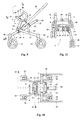
Figure 1 shows a perspective view of a stroller with an infant carrier, -
Figure 2 shows a perspective view of a stroller with a child seat for elder children, -
Figure 3 shows a perspective view of the stroller offigure 2 with the support bar for the child seat, -
Figure 4 shows the stroller offigure 3 in side view, -
Figure 5 shows the stroller offigure 4 whereby the support bar is tilted, -
Figure 6 shows the stroller offigure 4 whereby the stroller is partly folded, -
Figure 7 shows the stroller offigure 4 whereby the stroller is completely folded and the push bar is upright, -
Figure 8 shows the stroller offigure 4 whereby the stroller is completely folded and the push bar is flat, -
Figure 9 shows a side view of the stroller offigure 1 without the infant carrier, -
Figure 10 shows a top view perpendicular to the plane of the first wheel arms and the upper and lower frames, and -
Figure 11 shows a side view and section perpendicular to the plane of the first wheel arms and the upper and lower frames. -
Figure 1 shows astroller 1 with aninfant carrier 2, whichinfant carrier 2 has acarrier frame 3 that is mounted on asupport bracket 5 of thestroller 1. Thestroller 1 has twofirst wheel sets 11 and twosecond wheel sets 13. Each wheel set can pivot around a vertical axis in awheel pivot 10. In the illustrated embodiment, thestroller 1 haswheel sets upper frame 15 and alower frame 8 which frames 8, 15 can move relative one another and are connected by arail 17 which is fastened to thelower frame 8 and can slide in arail guide 36 of the upper frame 15 (seefigure 10 ). Thefirst wheel set 11 is mounted at one end of afirst wheel arm 9, the other end of thefirst wheel arm 9 is coupled to theupper frame 15. For support and stabilizing thefirst wheel arm 9 is supported in and can slide through a bearing bush 29 (seefigures 4 - 11 ) which is mounted in thelower frame 8. Thesecond wheel set 13 is mounted at one end of thesecond wheel arm 12; the other end of thesecond wheel arm 12 is fastened to thelower frame 8. For support and stabilizing the second wheel arm 12 abar 14 connects thesecond wheel arm 12 approximately in the middle to theupper frame 15. - Each
support bracket 5 is connected by alower support bar 6 to thelower frame 8 and by anupper support bar 16 to theupper frame 15. For pushing the stroller 1 apush bar 18 is connected by apush bar axis 7 to theupper frame 15. For uncoupling theinfant carrier 2 from thestroller 1 thesupport bracket 5 has a release button (not shown). For setting the tilting angle of thesupport bracket 5 thesupport bracket 5 has a setting button 4. -
Figure 2 shows thestroller 1 with achild seat 21 with aseat frame 20 mounted on thesupport bracket 5. Theseat frame 20 is part of thechild seat 21 which includes ahood 19 and aleg support 22 that might be swivable in order to adjust thechild seat 21. Thefigures 3 - 8 show how thestroller 1 is folded and the movements of thesupport bracket 5 with theseat frame 20 that represents the frame of thechild seat 21. -
Figure 3 and figure 4 show thestroller 1 in the same position as shown infigure 2 whereby only theseat frame 20 is visible and whereby the other parts of thechild seat 21 are not shown.Figure 3 shows that the U - shapedupper support bar 16 can rotate in an upper support bar bearing 25 and the U - shapedlower support bar 6 can rotate in a lower support bar bearing 23. The upper support bar bearing 25 is part of theupper frame 15 and the lower support bar bearing 23 is part of thelower frame 8.Figure 4 shows in interrupted lines that thelower support bar 6 and in the shown embodiment theupper support bar 16 are coupled to thesupport bracket 5 with slides which give this connection stability so that thesupport bracket 5 is firmly supported on thestroller 1. In another embodiment, seefigures 6 - 8 , only thelower support bar 6 has at its end a slide that slides in thesupport bracket 5 and theupper support bar 16 is connected with a pivot to the slide that is part of thelower support bar 6. - Each
first wheel arm 9 is coupled to theupper frame 15 by awheel arm pivot 27 that has a rotation axis that is perpendicular to therail 17. Thefirst wheel arm 9 slides through abearing bush 29 which can rotate around an axis parallel to the rotation axis ofwheel arm pivot 27. As these rotation axes are both perpendicular to therail 17, bothfirst wheel arms 9 move in a plane parallel to therail 17 when the distance between the rotation axes changes during folding or unfolding of thestroller 1. When folding or unfolding thestroller 1 therail 17, which is connected to thelower frame 8, moves along a rail guide 36 (seefigure 10 ) in theupper frame 15 and the distance between theupper frame 15 and thelower frame 8 changes. During this movement, thefirst wheel arm 9 makes a changing angle with the direction of movement alongrail 17, which angle increases as theupper frame 15 moves towards thelower frame 8. The distance between the twofirst wheel sets 11 increases thereby from approximately the width of thelower frame 8, for instance from 0,30 - 0,40m, to the distance suitable for use of thestroller 1, for instance approximately 0,60m. Thewheel arm pivot 27 and thebearing 29 rotate respectively in theupper frame 15 and thelower frame 8 around a single axis which can be effected in a construction in a stable way with little backlash and thefirst wheel arm 9 is guided in a stable way. - In the shown embodiment, there is a
single rail 17, which is oval and enclosed by theoval rail guide 36 so that theupper frame 15 and thelower frame 8 cannot rotate relative one another. Instead of onerail 17 the same effect can be obtained in a design for instance with tworails 17 that can be a round shaft whereby therail guide 36 is formed by two round bearings. - Each
second wheel arm 12 is coupled with its end to thelower frame 8 by awheel arm pivot 26. Along its length, for instance approximately in its middle thesecond wheel arm 12 is connected with thebar 14 by apivot 28 and by apivot 30 to theupper frame 15. The rotation axes of thewheel arm pivot 26 and thepivots second wheel arms 12 move in planes that makes an angle of approximately 30 degrees with each other. Thepivots - When the
stroller 1 is in folded condition whereby the distance between theupper frame 15 and thelower frame 8 is maximal asecond wheel arm 12 is more or less in the plane of thefirst wheel arms 9. The distance between the second wheel sets 13 is then approximately the same as the distance between the first wheel sets 11 for instance between 0,30m and 0,40m. As the plane in which thesecond wheel arm 12 moves makes an angle with the plane in which thelower frame 8 and theupper frame 15 move, the distance between the second wheel sets 13 increases as thestroller 1 unfolds. In unfolded condition, this distance is more or less the same as the distance between the first wheel sets 11, for instance 0,60m. - The plane in which the
lower frame 8 and theupper frame 15 move makes in the unfolded condition, which is the condition of use, an angle of approximately 30 - 40 degrees with the plane on which the first wheel sets 11 and the second wheel sets 13 are placed. During folding, this angle reduces to approximately zero. Thesupport bracket 5 is coupled to both theupper frame 15 and thelower frame 8 respectively by theupper support bar 16 and thelower support bar 6. As thestroller 1 folds the distance between theupper frame 15 and thelower frame 8 increases. By this movement the distance between thesupport bracket 5 and the plane of theupper frame 15 and thelower frame 8 decreases so that in folded condition (seefigure 7 and 8 ) the height of thesupport bracket 5 above the wheels is reduced, which makes the foldedstroller 1 easier to store. Also the orientation of thesupport bracket 5 in the folded situation is such that theseat frame 20 is approximately parallel to the plane of theupper frame 15 andlower frame 8 and the floor on which the foldedstroller 1 is standing. Thehood 19 can be folded in the plane of theseat frame 20, which reduces the volume of the foldedstroller 1 so there is no need to remove thechild seat 21 from thestroller 1. -
Figure 5 shows thestroller 1 offigure 4 whereby theseat frame 20 has been tilted. As can be seen thesupport bracket 5 has been rotated along the slide connected to thelower support bar 6. -
Figure 6 shows thestroller 1 offigure 4 whereby theupper support bar 16 is pivotable connected to the slide of thelower support bar 6 mounted in thesupport bracket 5. Thefigure 6 shows therail 17 halfway in theupper frame 15, so that there is a distance between theupper frame 15 and thelower frame 8. The bearingbush 29 is approximately halfway thefirst wheel arm 9 and thebar 14 has moved thesecond wheel arm 12 towards theupper frame 15. Thesupport bracket 5 is low and near theupper frame 15. -
Figure 7 and figure 8 show thestroller 1 offigure 6 completely folded and thefirst wheel arm 9 and the second wheel arm 12 (together with the bar 14) are more or less in the same plane as theupper frame 15 and thesecond frame 8. The push bar can be positioned above theupper frame 15, seefigure 7 , or in the same plane as thewheel arms upper frame 15, seefigure 8 . - In a further embodiment (not shown) it is possible to design the upper support bar bearing 25 and/or the lower support bar bearing 23 in such a way that when the
stroller 1 is in folded condition respectively theupper support bar 16 and/or thelower support bar 6 can be uncoupled from thebearing upper support bar 16 or thelower support bar 6 thesupport brackets 5 can be moved away from theupper frame 15. If for instance theupper support bar 16 can be moved out of the upper support bar bearing 25 by removing a cover, thesupport bracket 5 can swivel in the lower support bar bearing 23 and can be located between the push bar 18 (seefigure 8 ) so that the height of the foldedstroller 1 is further reduced. - According to another embodiment (not shown) the
upper frame 15 and thelower frame 8 are designed such that in folded condition thesupport bracket 5 fits between theframes wheel arms upper frame 15 and thelower frame 8 respectively. -
Figure 9 shows thestroller 1 offigure 1 without theinfant carrier 2. Theinfant carrier 2 can be supported on asupport surface 40 of thesupport bracket 5. In the support bracket 5 a firstarcuate slide 32 which is connected to thelower support bar 6 can slide along an arcuate path. A secondarcuate slide 33, which is connected to theupper support bar 16, can slide in the firstarcuate slide 32. Thesupport bracket 5 can rotate over a considerable angle relative to thestroller 1, which is suitable for the use with child seats for older children. For use with aninfant carrier 2 such as shown infigure 1 this is undesirable and therefore thesupport bracket 5 includes asignal pin 31, that extends above thesupport surface 40 and that is activated by those child seats for which the rotation of thesupport bracket 5 must be limited. When activated, thesignal pin 31 blocks the path of the firstarcuate slide 32 and thereby prevents rotation of thesupport bracket 5 to undesirable angles. - At the end of
rail 17, afold button 34 is placed. Activation of thefold button 34 makes it possible thatrail 17 slides in therail guide 36 that is part of the upper frame 15 (seefigure 10 ). It might be sufficient for folding thestroller 1 to push thefold button 34. It is however preferred that the user takes two separate actions. In this embodiment, the user first unlocks the swivelling of thepush bar 18 by pressing a push bar release button 39 (seefigure 11 ) and brings thepush bar 18 approximately in the plane of therail 17. The user then places his or her foot on thefold button 34 and pushes therail 17 into theupper housing 15 while pulling on thepush bar 18. Thestroller 1 now folds and thefold button 34 lowers towards the ground while thepush bar 18 slightly rotates in thepush bar bearing 24. When thestroller 1 is completely folded, therail 17 locks in the upper frame 15 (not shown). -
Figure 10 shows thestroller 1 in unfolded position in the view perpendicular to the plane of thefirst wheel arms 9, theupper frame 15 andrail 17.Figure 11 shows the front view and partially a section perpendicular to this plane. Agas spring 35 is mounted inrail 17 whereby its one end is coupled to therail 17 and via therail 17 to thelower frame 8 and its other end via abracket 37 to theupper frame 15. During folding of thestroller 1 therail 17 is pressed into theupper frame 15 and slides along therail guide 36 and the gas in thegas spring 35 is compressed. As therail 17 is moved by a foot of the user the additional force of thegas spring 35 is hardly noticed. For unfolding thestroller 1 therail 17 is unlocked in the upper frame 15 (not shown) and thegas spring 35 pushes therail 17 out of theupper frame 15 and thelower frame 8 and theupper frame 15 move towards each other. This movement pushes thesecond wheel arms 12 downwards and theupper frame 15 upwards and the second wheel sets 13 move outwards. The first wheel arms slide through the bearingbushes 29 and fold outwards until the stroller is completely unfolded and therail 17 is locked in its unfolded position. Now thepush bar 18 is brought in its position of use and locked in that position and thestroller 1 is ready for use.
Claims (10)
- Device for transporting a child in a child seat (2) comprising a first frame (15), a second frame (8), a linear guide (17, 36), two first wheel arms (9) and two second wheel arms (12), the wheel arms having at their wheel ends one or more wheels (11,13), whereby each wheel arm is coupled to both the first frame and the second frame and the first frame and the second frame are movable relative to one another along the linear guide for folding and unfolding the wheel arms characterized in that the first wheel arms (9) are connected at their other ends by a first pivot (27) to the first frame (15) and move during folding or unfolding in a common plane whereby a slide (29) that is connected by a second pivot (29) to the second frame (8) can move along the length of each first wheel arm.
- Device in accordance with claim 1 whereby the distance between the first pivots (27) is shorter than the distance between the second pivots (29).
- Device in accordance with claim 1 or 2 whereby the other ends of the second wheel arms (12) are coupled by a third pivot (26) to the second frame (8) and by a coupling bar (14) to the first frame (15).
- Device in accordance with claim 3 whereby the second wheel arms (12) are coupled such to the first frame (15) and the second frame (8) that they can pivot in two planes making a sharp angle.
- Device in accordance with one of the previous claims whereby spring means (35) can push the first frame (15) towards the second frame (8).
- Device in accordance with claim 5 whereby the first frame (15) or the second frame (8) is coupled to a foot support (34) for pushing with a foot against the spring force and the other frame has a handle (18) for holding it during pushing on the foot support.
- Device in accordance with one of the previous claims whereby the child seat (2) is coupled to a support bracket (5) which is connected by a first support bar (16) to the first frame (15) and by a second support bar (6) to the second frame (8).
- Device in accordance with claim 7 whereby the support bracket (5) comprises an arc shaped guide in which a slide (32) can move and whereby the first support bar (16) and/or the second support bar (6) are connected to the slide.
- Child seat suitable for use with the device in accordance with claim 7 or 8 whereby the largest distance between the connecting and/or supporting points (40) on a support bracket (5) is at least one third of the distance between the two brackets.
- Child seat in accordance with claim 9 whereby the child seat (2) has at least four connecting and/or supporting points (40) connectable to the two support brackets (5) .
Priority Applications (1)
| Application Number | Priority Date | Filing Date | Title |
|---|---|---|---|
| EP08102683.3A EP1970283A3 (en) | 2007-03-15 | 2008-03-17 | Device for transporting a child |
Applications Claiming Priority (2)
| Application Number | Priority Date | Filing Date | Title |
|---|---|---|---|
| EP07104251A EP1970282A1 (en) | 2007-03-15 | 2007-03-15 | Device for transporting a child |
| EP08102683.3A EP1970283A3 (en) | 2007-03-15 | 2008-03-17 | Device for transporting a child |
Publications (2)
| Publication Number | Publication Date |
|---|---|
| EP1970283A2 true EP1970283A2 (en) | 2008-09-17 |
| EP1970283A3 EP1970283A3 (en) | 2014-11-05 |
Family
ID=38068898
Family Applications (2)
| Application Number | Title | Priority Date | Filing Date |
|---|---|---|---|
| EP07104251A Withdrawn EP1970282A1 (en) | 2007-03-15 | 2007-03-15 | Device for transporting a child |
| EP08102683.3A Withdrawn EP1970283A3 (en) | 2007-03-15 | 2008-03-17 | Device for transporting a child |
Family Applications Before (1)
| Application Number | Title | Priority Date | Filing Date |
|---|---|---|---|
| EP07104251A Withdrawn EP1970282A1 (en) | 2007-03-15 | 2007-03-15 | Device for transporting a child |
Country Status (3)
| Country | Link |
|---|---|
| US (1) | US20080224451A1 (en) |
| EP (2) | EP1970282A1 (en) |
| CN (1) | CN101284543A (en) |
Cited By (3)
| Publication number | Priority date | Publication date | Assignee | Title |
|---|---|---|---|---|
| WO2012075157A2 (en) * | 2010-11-30 | 2012-06-07 | Kolcraft Enterprises, Inc. | Maneuverable strollers |
| US8882134B2 (en) | 2013-01-07 | 2014-11-11 | Kolcraft Enterprises, Inc. | Maneuverable strollers |
| US11292499B2 (en) | 2013-01-07 | 2022-04-05 | Kolcraft Enterprises, Inc. | Maneuverable strollers |
Families Citing this family (14)
| Publication number | Priority date | Publication date | Assignee | Title |
|---|---|---|---|---|
| US8251382B2 (en) * | 2007-06-06 | 2012-08-28 | Wonderland Nurserygoods Co., Ltd. | Stroller and seat assembly mechanism for a stroller |
| US7571926B2 (en) * | 2007-07-12 | 2009-08-11 | Ming-Tai Huang | Foldable toy stroller |
| US20100052277A1 (en) * | 2008-09-04 | 2010-03-04 | Dynamic Brands, Llc | Stroller accessory |
| US9944305B2 (en) | 2008-12-04 | 2018-04-17 | Baby Jogger, LLC | Removable seat attachment for a stroller |
| CN103921830B (en) | 2008-12-04 | 2016-05-25 | 戴那米克品牌股份有限公司 | For the seat attachment of stroller |
| CN101898579B (en) * | 2010-07-29 | 2012-11-07 | 好孩子儿童用品有限公司 | Baby carrier |
| CN101973301B (en) * | 2010-09-29 | 2012-06-13 | 好孩子儿童用品有限公司 | Baby carriage |
| FR2989661B1 (en) * | 2012-04-23 | 2015-02-20 | Dorel France Sa | STROLLER WITH SEVERAL TRANSPORT POSITIONS. |
| US9227648B2 (en) * | 2012-10-09 | 2016-01-05 | Dorel Juvenile Group, Inc. | Compactible stroller |
| EP2871112B1 (en) | 2013-11-01 | 2017-10-11 | Thule Child Transport Systems Ltd | Foldable carriage |
| US9517787B2 (en) * | 2014-08-14 | 2016-12-13 | Baby Jogger Llc | Baby stroller |
| TWM521572U (en) * | 2015-12-24 | 2016-05-11 | Unique Product & Design Co Ltd | Structure for baby stroller |
| US10106187B1 (en) * | 2016-08-18 | 2018-10-23 | Mark Edward Farrar | Baby carrier device |
| DE102016123514B4 (en) * | 2016-12-06 | 2023-02-02 | Emmaljunga Barnvagnsfabrik Ab | folding frame |
Family Cites Families (10)
| Publication number | Priority date | Publication date | Assignee | Title |
|---|---|---|---|---|
| US3100651A (en) * | 1961-09-29 | 1963-08-13 | George Lynn Garff | Stroller chassis child's support structure |
| BE793645A (en) * | 1972-01-03 | 1973-07-03 | Lines Walter M | WHEEL STROLLER |
| IT1005425B (en) * | 1974-01-24 | 1976-08-20 | Giordani Raffaele | STROLLER FOR CHILDREN WITH REDUCABLE SIZE |
| NL1017805C2 (en) * | 2001-04-09 | 2002-10-10 | All Our Kids Europ B V | Foldable child carriage has at least one front wheel and two rear wheels, all of which are pivotably connected with central frame part |
| FR2850073B1 (en) * | 2003-01-17 | 2006-03-17 | Gh Solutions | DEPLOYABLE SEAT |
| NZ548224A (en) * | 2005-07-01 | 2007-11-30 | Britax Childcare Pty Ltd | Stroller seat attachment for accommodating infant or toddler, being foldable to collapsed configuration |
| PT1741614E (en) * | 2005-07-07 | 2010-09-02 | Jane Sa | A foldable chassis for baby carriages |
| US7441794B2 (en) * | 2005-09-26 | 2008-10-28 | Red Lan | Foldable stroller |
| US7681894B2 (en) * | 2006-02-14 | 2010-03-23 | Jane, S.A. | Device for fitting seats and the like to the chassis of baby carriages |
| US7607725B2 (en) * | 2006-08-16 | 2009-10-27 | Promen-Aid Innovations Ltd. | Collapsible support structure |
-
2007
- 2007-03-15 EP EP07104251A patent/EP1970282A1/en not_active Withdrawn
-
2008
- 2008-03-14 US US12/048,818 patent/US20080224451A1/en not_active Abandoned
- 2008-03-17 EP EP08102683.3A patent/EP1970283A3/en not_active Withdrawn
- 2008-03-17 CN CNA2008100861556A patent/CN101284543A/en active Pending
Non-Patent Citations (1)
| Title |
|---|
| None |
Cited By (7)
| Publication number | Priority date | Publication date | Assignee | Title |
|---|---|---|---|---|
| WO2012075157A2 (en) * | 2010-11-30 | 2012-06-07 | Kolcraft Enterprises, Inc. | Maneuverable strollers |
| WO2012075157A3 (en) * | 2010-11-30 | 2012-12-27 | Kolcraft Enterprises, Inc. | Maneuverable strollers |
| US9056622B2 (en) | 2010-11-30 | 2015-06-16 | Kolcraft Enterprises, Inc. | Maneuverable strollers |
| US8882134B2 (en) | 2013-01-07 | 2014-11-11 | Kolcraft Enterprises, Inc. | Maneuverable strollers |
| US9260127B2 (en) | 2013-01-07 | 2016-02-16 | Kolcraft Enterprises, Inc. | Maneuverable strollers |
| US10556610B2 (en) | 2013-01-07 | 2020-02-11 | Kolcraft Enterprises, Inc. | Method for manufacturing maneuverable strollers |
| US11292499B2 (en) | 2013-01-07 | 2022-04-05 | Kolcraft Enterprises, Inc. | Maneuverable strollers |
Also Published As
| Publication number | Publication date |
|---|---|
| US20080224451A1 (en) | 2008-09-18 |
| EP1970283A3 (en) | 2014-11-05 |
| CN101284543A (en) | 2008-10-15 |
| EP1970282A1 (en) | 2008-09-17 |
Similar Documents
| Publication | Publication Date | Title |
|---|---|---|
| EP1970283A2 (en) | Device for transporting a child | |
| CN101448695B (en) | Handle for collapsible stroller | |
| JP5516906B2 (en) | Folding push chair | |
| CN105835933B (en) | Easy-to-operate perambulator | |
| US8366141B2 (en) | Transporter | |
| TWI413595B (en) | Baby carriage | |
| JP2003189968A (en) | Foldable chair | |
| US11292499B2 (en) | Maneuverable strollers | |
| EP1986908B1 (en) | Stroller | |
| NZ575551A (en) | A pram with a removeable sub-frame | |
| EP0908370A2 (en) | Foldable stroller | |
| US10850760B2 (en) | Foldable wheeled carrier including wheel folding actuation handle | |
| EP3127775B1 (en) | Cart | |
| MXPA05007624A (en) | Collapsible structure system. | |
| US6805406B1 (en) | Seat for a wheeled carriage or chair | |
| EP2421740B1 (en) | Stroller or buggy | |
| CN107928246A (en) | Children dinning chair | |
| WO2020029751A1 (en) | Baby stroller | |
| CN209519001U (en) | Wheelchair and wheelchair system with scalable wheel | |
| AU2004205538A2 (en) | Collapsible seat with a collapsible protective structure | |
| WO2020029456A1 (en) | Stroller | |
| CN212099030U (en) | Baby carriage with automatically-folded backrest | |
| CN216153850U (en) | Novel baby carriage | |
| CN207328551U (en) | Foldable chassis and there is its trolley | |
| CN115606966A (en) | Infant bouncer |
Legal Events
| Date | Code | Title | Description |
|---|---|---|---|
| PUAI | Public reference made under article 153(3) epc to a published international application that has entered the european phase |
Free format text: ORIGINAL CODE: 0009012 |
|
| AK | Designated contracting states |
Kind code of ref document: A2 Designated state(s): AT BE BG CH CY CZ DE DK EE ES FI FR GB GR HR HU IE IS IT LI LT LU LV MC MT NL NO PL PT RO SE SI SK TR |
|
| AX | Request for extension of the european patent |
Extension state: AL BA MK RS |
|
| PUAL | Search report despatched |
Free format text: ORIGINAL CODE: 0009013 |
|
| AK | Designated contracting states |
Kind code of ref document: A3 Designated state(s): AT BE BG CH CY CZ DE DK EE ES FI FR GB GR HR HU IE IS IT LI LT LU LV MC MT NL NO PL PT RO SE SI SK TR |
|
| AX | Request for extension of the european patent |
Extension state: AL BA MK RS |
|
| RIC1 | Information provided on ipc code assigned before grant |
Ipc: B62B 7/06 20060101AFI20140930BHEP |
|
| AKY | No designation fees paid | ||
| AXX | Extension fees paid |
Extension state: MK Extension state: BA Extension state: RS Extension state: AL |
|
| REG | Reference to a national code |
Ref country code: DE Ref legal event code: R108 |
|
| STAA | Information on the status of an ep patent application or granted ep patent |
Free format text: STATUS: THE APPLICATION IS DEEMED TO BE WITHDRAWN |
|
| 18D | Application deemed to be withdrawn |
Effective date: 20150507 |