EP1970277A1 - Cap and axle-box with said cap - Google Patents
Cap and axle-box with said cap Download PDFInfo
- Publication number
- EP1970277A1 EP1970277A1 EP08004322A EP08004322A EP1970277A1 EP 1970277 A1 EP1970277 A1 EP 1970277A1 EP 08004322 A EP08004322 A EP 08004322A EP 08004322 A EP08004322 A EP 08004322A EP 1970277 A1 EP1970277 A1 EP 1970277A1
- Authority
- EP
- European Patent Office
- Prior art keywords
- cap
- bearing
- cap according
- gap
- axle
- Prior art date
- Legal status (The legal status is an assumption and is not a legal conclusion. Google has not performed a legal analysis and makes no representation as to the accuracy of the status listed.)
- Granted
Links
Images

Classifications
-
- B—PERFORMING OPERATIONS; TRANSPORTING
- B61—RAILWAYS
- B61F—RAIL VEHICLE SUSPENSIONS, e.g. UNDERFRAMES, BOGIES OR ARRANGEMENTS OF WHEEL AXLES; RAIL VEHICLES FOR USE ON TRACKS OF DIFFERENT WIDTH; PREVENTING DERAILING OF RAIL VEHICLES; WHEEL GUARDS, OBSTRUCTION REMOVERS OR THE LIKE FOR RAIL VEHICLES
- B61F15/00—Axle-boxes
- B61F15/20—Details
- B61F15/26—Covers; Sealing thereof
Definitions
- the invention relates to a cap and axle-box with said cap.
- axle-box In railway applications the use of an axle-box is well known for example as a part of a bogie.
- a bearing particularly a rolling bearing, is mounted on an axial end of the axle, for example by pressing an inner ring of the bearing in an axial direction against a shoulder of the axle by screwing a cover plate onto the front side of the axle.
- two basic designs are known how to mount the bearing in the axle-box.
- an outer ring of the bearing fits in a corresponding opening of the axle-box. Then the opening of the axle-box with the bearing inside is closed by cap, which is for example screwed to the axle-box and fixes the outer ring by pressing the outer ring in an axial direction against as step in the opening.
- the outer ring of the bearing is located in an opening of the axle-box, whereby the opening is designed so, that under normal operating conditions the outer bearing ring contacts the opening only in a corresponding recess in an upper sector-like region of the opening, and that the outer ring has a gap to the opening in a lower region.
- the second design has the advantage that the axle-box can be removed from the axle with thereon mounted bearing in a comparatively easy manner by lifting the axle-box being helpful for mounting and dismounting operations. Under normal conditions an unhinging of the bearing is prevented by closing said gap with a polymer block being fixed in a detachable manner in said gap.
- one object of the present invention is to provide an improvement for a bearing arrangement.
- a cap for a bearing arrangement comprises a hollow-cylindrical bearing element being arrangable in an opening of a housing element, thereby the bearing arrangement is designed so, that under normal operation conditions the outer jacket of the bearing element contacts the opening basically in a sector-like region and has an gap in a region opposing the contacting region, whereby the cap is designed to close the opening and the cap comprises an axial projection being designed at least to project between the bearing element and the housing element in said region with said gap to essentially close said gap at least in a radial direction.
- the invention is based on the following cognitions:
- a good protection against environmental effects is achieved by using a cap similar as in the first design.
- the block closing said gap in said second design is an integral part of said cap, so that with advantage the number of separate parts is reduced also disburdening mounting and dismounting.
- the cap provides with advantage a good protection against environmental effects like water infiltration and also ballast, which can be projected against the bearing arrangement. So the cap also acts as a protection shield for the bearing preventing direct exposure of the bearing particularly its seals to any physical aggression, e.g. high pressure de-icing, snow, ice, sand and so on. Further the cap gives said second design a closed axle-box look.
- hot box detection systems by making particularly the whole cap of a thermally good conducting material for example of steel.
- hot box detection in relation with the second design as described in the beginning results sometime in false alarms, because the area scanned by the hot box detecting system located in the lower region of the axle-box arrangement comprises seals or sealing shields of the bearing, which both can become comparatively warm also in faultless conditions of the bearing. Now with the cap such false alarms are avoidable because a direct scanning of these elements is no longer possible.
- the cap ensures via said gap-bridging projection made of a thermally good conducting material a good thermal transfer from the bearing to the lower regions of the axle-box being scanned by the hot box detection system, so that real fault conditions of the bearing are nevertheless reliably detected by the hot box detection system.
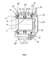
- Figure 1 shows as one embodiment of the invention a longitudinal cross section of a railway axle bearing arrangement.
- a double row tapered roller bearing is mounted on a trunnion of the axle 2 at the axial end of the axle 2.
- the rolling bearing comprises two inner rings 11 and 12, one for each row of the tapered rollers 20. Between the two facing end faces of the two inner rings 11 and 12 a distance ring 14 is arranged. Further the rolling bearing comprises a one-piece outer ring 30 for both rows of rollers 20.
- Each row of rollers 20 is arranged in a cage 21 and 22 and the space comprising the two rows of rollers 20 between the outer ring 30 and the inner rings 11 and 12 is sealed at both axial ends of the bearing with seals 25 of the contacting type.
- the bearing is designed as a grease lubricated bearing.
- the rolling bearing can also be sealed with labyrinth seals or with one another engaging shields.
- the rolling bearing is fixed on the end of the axle 2 in the way that the two inner rings 11 and 12 and the distance ring 14 are pressed via a polymer spacer 16 and a special designed adapter ring 17 against a shoulder of the axle 2 by a cover plate 18 which is screwed to the end of the axle 2.
- the outer ring 30 of the rolling bearing is arranged in an opening of an axle-box 40.
- this opening has at least in a sector of its upper half a shape corresponding to the outer jacket of the outer ring 30. Particularly in the lower half the opening is designed with a radial gap in relation to the bearing outer ring 30. This enables an easy dismounting of the rolling bearing from the axle-box 40 by just lifting the axle-box 40.
- FIGS. 2 and 3 show perspective views of the cap 50.
- the cap 50 has on the left end face a hollow-cylindrical projection 52 in the axial direction, which is at least in the upper half of the bearing arrangement designed so, that the end face of this projection 52 effects the end face of the bearing outer ring 30, so that the outer ring 30 is clamped in a radial direction in the axle-box 40 by screwing the cap 50 to the axle-box 40.
- the projection 52 extending between a part of the outer jacket of the outer ring 30 and an inner jacket of the opening extends further in the axial direction and has a greater radial thickness than in the upper half of the bearing arrangement.
- the part of the cap 50 extending between the outer jacket of the outer ring 30 and the inner jacket of the opening ensures a good thermal transfer from the bearing to the axle-box 40 and the cap 50 in this region, which is important for a reliable hot box detection as described in the beginning.
- the inner jacket of said part of the cap 50 is designed with an axially extending groove 54 enabling with advantage a drainage of water and an escape of dust and particles from the space closed by the cap 50.
- the cap 50 is designed in a twelve o'clock position with a radially projecting ear 56, where another element can be connected for example a T-bar, whereby then the T-bar can be connected with a bogie frame for example via a damper.
- the ear 56 comprises an opening to connect the T-bar with the ear 56 by a screw.
- the bearing outer ring 30 can be fixed in a radial direction in an opening of an axle-box so, that also the right axial end of the axle-box opening is designed similar to the left axial end as shown in figure 1 .
- the hollow-cylindrical projection of a cap is at least in the upper half of the arrangement adapted so, that it is short enough to not come into conflict with said type of axial fixation of bearing outer ring. In a sector around the six o'clock position the cap so can stay essentially unmodified.
- the cap 50 of figure 1 of course can also be designed without said ear 56.
- the cap 50 can be made of steel or cast iron or any suitable material in view of hardness, thermal conductibility and so on.
- the cap is still one piece but comprises different materials in different regions.
Landscapes
- Engineering & Computer Science (AREA)
- Mechanical Engineering (AREA)
- Rolling Contact Bearings (AREA)
Abstract
Description
- The invention relates to a cap and axle-box with said cap.
- In railway applications the use of an axle-box is well known for example as a part of a bogie. Thereby a bearing, particularly a rolling bearing, is mounted on an axial end of the axle, for example by pressing an inner ring of the bearing in an axial direction against a shoulder of the axle by screwing a cover plate onto the front side of the axle. Thereby two basic designs are known how to mount the bearing in the axle-box.
- According to a first design an outer ring of the bearing fits in a corresponding opening of the axle-box. Then the opening of the axle-box with the bearing inside is closed by cap, which is for example screwed to the axle-box and fixes the outer ring by pressing the outer ring in an axial direction against as step in the opening. According to a second design the outer ring of the bearing is located in an opening of the axle-box, whereby the opening is designed so, that under normal operating conditions the outer bearing ring contacts the opening only in a corresponding recess in an upper sector-like region of the opening, and that the outer ring has a gap to the opening in a lower region.
- Thereby the second design has the advantage that the axle-box can be removed from the axle with thereon mounted bearing in a comparatively easy manner by lifting the axle-box being helpful for mounting and dismounting operations. Under normal conditions an unhinging of the bearing is prevented by closing said gap with a polymer block being fixed in a detachable manner in said gap.
- Further also for railway overheating of bearings is an issue, so that the use of wayside hot box detecting systems is also well known.
- So one object of the present invention is to provide an improvement for a bearing arrangement.
- This object of the invention is achieved by subject of claims 1 and 15. Preferable embodiments are described in the other dependent claims.
- According to claim 1 a cap for a bearing arrangement comprises a hollow-cylindrical bearing element being arrangable in an opening of a housing element, thereby the bearing arrangement is designed so, that under normal operation conditions the outer jacket of the bearing element contacts the opening basically in a sector-like region and has an gap in a region opposing the contacting region, whereby the cap is designed to close the opening and the cap comprises an axial projection being designed at least to project between the bearing element and the housing element in said region with said gap to essentially close said gap at least in a radial direction.
- Thereby the invention is based on the following cognitions: In said second design a good protection against environmental effects is achieved by using a cap similar as in the first design. Thereby the block closing said gap in said second design is an integral part of said cap, so that with advantage the number of separate parts is reduced also disburdening mounting and dismounting. Further the cap provides with advantage a good protection against environmental effects like water infiltration and also ballast, which can be projected against the bearing arrangement. So the cap also acts as a protection shield for the bearing preventing direct exposure of the bearing particularly its seals to any physical aggression, e.g. high pressure de-icing, snow, ice, sand and so on. Further the cap gives said second design a closed axle-box look.
- Furthermore another big advantage is achieved with respect to hot box detection systems by making particularly the whole cap of a thermally good conducting material for example of steel. Up to now hot box detection in relation with the second design as described in the beginning results sometime in false alarms, because the area scanned by the hot box detecting system located in the lower region of the axle-box arrangement comprises seals or sealing shields of the bearing, which both can become comparatively warm also in faultless conditions of the bearing. Now with the cap such false alarms are avoidable because a direct scanning of these elements is no longer possible. On the other hand the cap ensures via said gap-bridging projection made of a thermally good conducting material a good thermal transfer from the bearing to the lower regions of the axle-box being scanned by the hot box detection system, so that real fault conditions of the bearing are nevertheless reliably detected by the hot box detection system.
- Further advantages, features and details of the invention are described with respect to one embodiment of the invention with reference to the Figures.
- Figure 1
- is a longitudinal cross section of a railway axle bearing arrangement with a cap and
- Figure 2 and 3
- are perspective views of the cap of
figure 1 . -
Figure 1 shows as one embodiment of the invention a longitudinal cross section of a railway axle bearing arrangement. Thereby a double row tapered roller bearing is mounted on a trunnion of theaxle 2 at the axial end of theaxle 2. The rolling bearing comprises twoinner rings 11 and 12, one for each row of thetapered rollers 20. Between the two facing end faces of the two inner rings 11 and 12 adistance ring 14 is arranged. Further the rolling bearing comprises a one-pieceouter ring 30 for both rows ofrollers 20. Each row ofrollers 20 is arranged in acage rollers 20 between theouter ring 30 and theinner rings 11 and 12 is sealed at both axial ends of the bearing withseals 25 of the contacting type. Thereby the bearing is designed as a grease lubricated bearing. In other embodiments the rolling bearing can also be sealed with labyrinth seals or with one another engaging shields. - The rolling bearing is fixed on the end of the
axle 2 in the way that the twoinner rings 11 and 12 and thedistance ring 14 are pressed via apolymer spacer 16 and a special designedadapter ring 17 against a shoulder of theaxle 2 by acover plate 18 which is screwed to the end of theaxle 2. Further theouter ring 30 of the rolling bearing is arranged in an opening of an axle-box 40. Thereby this opening has at least in a sector of its upper half a shape corresponding to the outer jacket of theouter ring 30. Particularly in the lower half the opening is designed with a radial gap in relation to the bearingouter ring 30. This enables an easy dismounting of the rolling bearing from the axle-box 40 by just lifting the axle-box 40. - The opening of the axle-
box 40 is closed by thecap 50, which is screwed to the axle-box 40 by screws. TherebyFigures 2 and 3 show perspective views of thecap 50. Thecap 50 has on the left end face a hollow-cylindrical projection 52 in the axial direction, which is at least in the upper half of the bearing arrangement designed so, that the end face of thisprojection 52 effects the end face of the bearingouter ring 30, so that theouter ring 30 is clamped in a radial direction in the axle-box 40 by screwing thecap 50 to the axle-box 40. - In a lower sector the
projection 52 extending between a part of the outer jacket of theouter ring 30 and an inner jacket of the opening extends further in the axial direction and has a greater radial thickness than in the upper half of the bearing arrangement. Thereby the part of thecap 50 extending between the outer jacket of theouter ring 30 and the inner jacket of the opening ensures a good thermal transfer from the bearing to the axle-box 40 and thecap 50 in this region, which is important for a reliable hot box detection as described in the beginning. Further the inner jacket of said part of thecap 50 is designed with an axially extendinggroove 54 enabling with advantage a drainage of water and an escape of dust and particles from the space closed by thecap 50. - Further the
cap 50 is designed in a twelve o'clock position with a radially projectingear 56, where another element can be connected for example a T-bar, whereby then the T-bar can be connected with a bogie frame for example via a damper. Theear 56 comprises an opening to connect the T-bar with theear 56 by a screw. - In another embodiment of the invention the bearing
outer ring 30 can be fixed in a radial direction in an opening of an axle-box so, that also the right axial end of the axle-box opening is designed similar to the left axial end as shown infigure 1 . Then of course the hollow-cylindrical projection of a cap is at least in the upper half of the arrangement adapted so, that it is short enough to not come into conflict with said type of axial fixation of bearing outer ring. In a sector around the six o'clock position the cap so can stay essentially unmodified. - In another embodiment the
cap 50 offigure 1 of course can also be designed without saidear 56. Thecap 50 can be made of steel or cast iron or any suitable material in view of hardness, thermal conductibility and so on. In another embodiment the cap is still one piece but comprises different materials in different regions.
Claims (15)
- Cap for a bearing arrangement comprising a hollow-cylindrical bearing element being arrangable in an opening of a housing element, thereby the bearing arrangement is designed so, that under normal operation conditions the outer jacket of the bearing element contacts the opening basically in a sector-like region and has an gap in a region opposing the contacting region, whereby the cap is designed to close the opening and the cap comprises an axial projection being designed at least to project between the bearing element and the housing element in said region with said gap to essentially close said gap at least in a radial direction.
- Cap according to claim 1, whereby the inner jacket of said gap-closing section of the cap comprises an axially extending groove.
- Cap according to one of the claims 1 or 2, whereby said cap is made of a thermally good conducting material at least in said gap-closing section.
- Cap according to claim 3, whereby the whole cap is made of said material.
- Cap according to one of the claims 3 or 4, whereby said material comprises metal, particularly steel or cast iron.
- Cap according to one of the claims 1 to 5, whereby the cap comprises another axial projection in said contacting region to press the bearing element against a bedstop of the housing element.
- Cap according to claim 6, whereby both projections are part of one circumferentially extending ring-like axial projection of the cap.
- Cap according to one of the claims 1 to 7, whereby the cap comprises a radially extending projection for connecting another element at said projection.
- Cap according to one of the claims 1 to 8, whereby said contacting section and/or said radially extending projection are located at a twelve o'clock position.
- Cap according to one of the claims 1 to 9, whereby the cap comprises at least two bores for fixing the cap to the housing element.
- Cap according to one of the claims 1 to 10, whereby the cap is designed to be screwed to the housing element.
- Cap according to one of the claims 1 to 11, whereby the bearing element is an outer ring of a rolling bearing.
- Cap according to claim 12, whereby the rolling bearing is a two row, particularly tapered roller bearing.
- Cap according to one of the claims 1 to 13, whereby the bearing arrangement belongs to an axle-box of a railway bogie.
- Axle-box with a cap according to one of the claims 1 to 14.
Priority Applications (1)
| Application Number | Priority Date | Filing Date | Title |
|---|---|---|---|
| EP20080004322 EP1970277B1 (en) | 2007-03-14 | 2008-03-08 | Cap and axle-box with said cap |
Applications Claiming Priority (2)
| Application Number | Priority Date | Filing Date | Title |
|---|---|---|---|
| EP07005251 | 2007-03-14 | ||
| EP20080004322 EP1970277B1 (en) | 2007-03-14 | 2008-03-08 | Cap and axle-box with said cap |
Publications (2)
| Publication Number | Publication Date |
|---|---|
| EP1970277A1 true EP1970277A1 (en) | 2008-09-17 |
| EP1970277B1 EP1970277B1 (en) | 2012-06-27 |
Family
ID=39326996
Family Applications (1)
| Application Number | Title | Priority Date | Filing Date |
|---|---|---|---|
| EP20080004322 Not-in-force EP1970277B1 (en) | 2007-03-14 | 2008-03-08 | Cap and axle-box with said cap |
Country Status (1)
| Country | Link |
|---|---|
| EP (1) | EP1970277B1 (en) |
Cited By (2)
| Publication number | Priority date | Publication date | Assignee | Title |
|---|---|---|---|---|
| CN110550059A (en) * | 2018-05-31 | 2019-12-10 | 斯凯孚公司 | Rail vehicle adapter for connecting a rail vehicle body to a bearing |
| CN110997445A (en) * | 2017-08-23 | 2020-04-10 | 舍弗勒技术股份两合公司 | Covering system for the axle of a wheel set of a rail vehicle |
Citations (6)
| Publication number | Priority date | Publication date | Assignee | Title |
|---|---|---|---|---|
| FR550487A (en) * | 1922-04-20 | 1923-03-10 | Ball box for axles of railways, trams, wagons, etc. | |
| FR714008A (en) * | 1931-03-28 | 1931-11-06 | An Officine Di Villar Perosa S | Device for wedging tapered or cylindrical roller bearings mounted in the axle boxes of railway or tram cars |
| US1984823A (en) * | 1930-04-29 | 1934-12-18 | Gen Motors Corp | Journal box |
| US2349073A (en) * | 1943-01-14 | 1944-05-16 | Gen Motors Corp | Railway journal box |
| US3531166A (en) * | 1968-09-06 | 1970-09-29 | Vitaly Vasilievich Dudin | Axle-box for the axle of pair of wheels of rolling stock |
| GB2058242A (en) * | 1979-07-06 | 1981-04-08 | Vandervell Products Ltd | Oil baffles in axle boxes |
-
2008
- 2008-03-08 EP EP20080004322 patent/EP1970277B1/en not_active Not-in-force
Patent Citations (6)
| Publication number | Priority date | Publication date | Assignee | Title |
|---|---|---|---|---|
| FR550487A (en) * | 1922-04-20 | 1923-03-10 | Ball box for axles of railways, trams, wagons, etc. | |
| US1984823A (en) * | 1930-04-29 | 1934-12-18 | Gen Motors Corp | Journal box |
| FR714008A (en) * | 1931-03-28 | 1931-11-06 | An Officine Di Villar Perosa S | Device for wedging tapered or cylindrical roller bearings mounted in the axle boxes of railway or tram cars |
| US2349073A (en) * | 1943-01-14 | 1944-05-16 | Gen Motors Corp | Railway journal box |
| US3531166A (en) * | 1968-09-06 | 1970-09-29 | Vitaly Vasilievich Dudin | Axle-box for the axle of pair of wheels of rolling stock |
| GB2058242A (en) * | 1979-07-06 | 1981-04-08 | Vandervell Products Ltd | Oil baffles in axle boxes |
Cited By (2)
| Publication number | Priority date | Publication date | Assignee | Title |
|---|---|---|---|---|
| CN110997445A (en) * | 2017-08-23 | 2020-04-10 | 舍弗勒技术股份两合公司 | Covering system for the axle of a wheel set of a rail vehicle |
| CN110550059A (en) * | 2018-05-31 | 2019-12-10 | 斯凯孚公司 | Rail vehicle adapter for connecting a rail vehicle body to a bearing |
Also Published As
| Publication number | Publication date |
|---|---|
| EP1970277B1 (en) | 2012-06-27 |
Similar Documents
| Publication | Publication Date | Title |
|---|---|---|
| US6179471B1 (en) | Device for mounting a sensor to a railway axle bearing unit | |
| CN105889331B (en) | Sealing assembly for a rolling bearing and hub bearing unit for a vehicle | |
| US9463814B2 (en) | Bearing device for axle of railway vehicle | |
| EP0127485B1 (en) | Sealed multi-row roller bearing device for rolling mills | |
| US10724577B2 (en) | Split bearing cartridge assembly and split housed bearing assembly | |
| US6109794A (en) | Rolling contact bearing provided with a seal and an electrostatic current discharge device | |
| EP2607733A1 (en) | Bearing unit for use in an axlebox of a railway vehicle and axlebox including the same | |
| US20090220182A1 (en) | Bearing apparatus for axle | |
| EP1970277B1 (en) | Cap and axle-box with said cap | |
| US10974740B2 (en) | Railcar adapter for connecting a railcar body to a bearing | |
| US5697710A (en) | Bearing seals and bearing and seal assemblies | |
| NL9401721A (en) | Rolling bearing with oil seal. | |
| US20160123470A1 (en) | Seal assembly | |
| US20190367053A1 (en) | Railcar adapter for connecting a railcar body to a bearing | |
| RU2469780C2 (en) | Window on pressure pipe | |
| JP3844767B2 (en) | Segment roll device | |
| JP3636786B2 (en) | Bearing sealing device | |
| RU2425767C1 (en) | Axle box bearing assembly | |
| US10710151B2 (en) | Seal cassette for a continuous casting machine | |
| JP2008249034A (en) | Bearing seal and rolling bearing | |
| US6375195B1 (en) | Sealing assembly | |
| RU2470728C2 (en) | Roll bearing and method of its mounting | |
| CA1324399C (en) | Rotary joint | |
| CN114056373B (en) | End cap assembly and axle box device | |
| RU2151927C1 (en) | Sealing unit of film lubrication bearing |
Legal Events
| Date | Code | Title | Description |
|---|---|---|---|
| PUAI | Public reference made under article 153(3) epc to a published international application that has entered the european phase |
Free format text: ORIGINAL CODE: 0009012 |
|
| 17P | Request for examination filed |
Effective date: 20080604 |
|
| AK | Designated contracting states |
Kind code of ref document: A1 Designated state(s): AT BE BG CH CY CZ DE DK EE ES FI FR GB GR HR HU IE IS IT LI LT LU LV MC MT NL NO PL PT RO SE SI SK TR |
|
| AX | Request for extension of the european patent |
Extension state: AL BA MK RS |
|
| 17Q | First examination report despatched |
Effective date: 20081028 |
|
| AKX | Designation fees paid |
Designated state(s): AT BE BG CH CY CZ DE DK EE ES FI FR GB GR HR HU IE IS IT LI LT LU LV MC MT NL NO PL PT RO SE SI SK TR |
|
| GRAP | Despatch of communication of intention to grant a patent |
Free format text: ORIGINAL CODE: EPIDOSNIGR1 |
|
| GRAS | Grant fee paid |
Free format text: ORIGINAL CODE: EPIDOSNIGR3 |
|
| GRAJ | Information related to disapproval of communication of intention to grant by the applicant or resumption of examination proceedings by the epo deleted |
Free format text: ORIGINAL CODE: EPIDOSDIGR1 |
|
| GRAL | Information related to payment of fee for publishing/printing deleted |
Free format text: ORIGINAL CODE: EPIDOSDIGR3 |
|
| GRAP | Despatch of communication of intention to grant a patent |
Free format text: ORIGINAL CODE: EPIDOSNIGR1 |
|
| GRAS | Grant fee paid |
Free format text: ORIGINAL CODE: EPIDOSNIGR3 |
|
| GRAA | (expected) grant |
Free format text: ORIGINAL CODE: 0009210 |
|
| AK | Designated contracting states |
Kind code of ref document: B1 Designated state(s): AT BE BG CH CY CZ DE DK EE ES FI FR GB GR HR HU IE IS IT LI LT LU LV MC MT NL NO PL PT RO SE SI SK TR |
|
| REG | Reference to a national code |
Ref country code: GB Ref legal event code: FG4D |
|
| REG | Reference to a national code |
Ref country code: CH Ref legal event code: EP |
|
| REG | Reference to a national code |
Ref country code: AT Ref legal event code: REF Ref document number: 564017 Country of ref document: AT Kind code of ref document: T Effective date: 20120715 |
|
| REG | Reference to a national code |
Ref country code: IE Ref legal event code: FG4D |
|
| REG | Reference to a national code |
Ref country code: DE Ref legal event code: R096 Ref document number: 602008016629 Country of ref document: DE Effective date: 20120823 |
|
| PG25 | Lapsed in a contracting state [announced via postgrant information from national office to epo] |
Ref country code: SE Free format text: LAPSE BECAUSE OF FAILURE TO SUBMIT A TRANSLATION OF THE DESCRIPTION OR TO PAY THE FEE WITHIN THE PRESCRIBED TIME-LIMIT Effective date: 20120627 Ref country code: LT Free format text: LAPSE BECAUSE OF FAILURE TO SUBMIT A TRANSLATION OF THE DESCRIPTION OR TO PAY THE FEE WITHIN THE PRESCRIBED TIME-LIMIT Effective date: 20120627 Ref country code: NO Free format text: LAPSE BECAUSE OF FAILURE TO SUBMIT A TRANSLATION OF THE DESCRIPTION OR TO PAY THE FEE WITHIN THE PRESCRIBED TIME-LIMIT Effective date: 20120927 Ref country code: FI Free format text: LAPSE BECAUSE OF FAILURE TO SUBMIT A TRANSLATION OF THE DESCRIPTION OR TO PAY THE FEE WITHIN THE PRESCRIBED TIME-LIMIT Effective date: 20120627 |
|
| REG | Reference to a national code |
Ref country code: NL Ref legal event code: VDEP Effective date: 20120627 |
|
| REG | Reference to a national code |
Ref country code: AT Ref legal event code: MK05 Ref document number: 564017 Country of ref document: AT Kind code of ref document: T Effective date: 20120627 |
|
| REG | Reference to a national code |
Ref country code: LT Ref legal event code: MG4D Effective date: 20120627 |
|
| PG25 | Lapsed in a contracting state [announced via postgrant information from national office to epo] |
Ref country code: SI Free format text: LAPSE BECAUSE OF FAILURE TO SUBMIT A TRANSLATION OF THE DESCRIPTION OR TO PAY THE FEE WITHIN THE PRESCRIBED TIME-LIMIT Effective date: 20120627 Ref country code: GR Free format text: LAPSE BECAUSE OF FAILURE TO SUBMIT A TRANSLATION OF THE DESCRIPTION OR TO PAY THE FEE WITHIN THE PRESCRIBED TIME-LIMIT Effective date: 20120928 Ref country code: HR Free format text: LAPSE BECAUSE OF FAILURE TO SUBMIT A TRANSLATION OF THE DESCRIPTION OR TO PAY THE FEE WITHIN THE PRESCRIBED TIME-LIMIT Effective date: 20120627 Ref country code: LV Free format text: LAPSE BECAUSE OF FAILURE TO SUBMIT A TRANSLATION OF THE DESCRIPTION OR TO PAY THE FEE WITHIN THE PRESCRIBED TIME-LIMIT Effective date: 20120627 |
|
| REG | Reference to a national code |
Ref country code: SK Ref legal event code: T3 Ref document number: E 12582 Country of ref document: SK |
|
| PG25 | Lapsed in a contracting state [announced via postgrant information from national office to epo] |
Ref country code: IS Free format text: LAPSE BECAUSE OF FAILURE TO SUBMIT A TRANSLATION OF THE DESCRIPTION OR TO PAY THE FEE WITHIN THE PRESCRIBED TIME-LIMIT Effective date: 20121027 Ref country code: RO Free format text: LAPSE BECAUSE OF FAILURE TO SUBMIT A TRANSLATION OF THE DESCRIPTION OR TO PAY THE FEE WITHIN THE PRESCRIBED TIME-LIMIT Effective date: 20120627 Ref country code: AT Free format text: LAPSE BECAUSE OF FAILURE TO SUBMIT A TRANSLATION OF THE DESCRIPTION OR TO PAY THE FEE WITHIN THE PRESCRIBED TIME-LIMIT Effective date: 20120627 Ref country code: CY Free format text: LAPSE BECAUSE OF FAILURE TO SUBMIT A TRANSLATION OF THE DESCRIPTION OR TO PAY THE FEE WITHIN THE PRESCRIBED TIME-LIMIT Effective date: 20120627 Ref country code: CZ Free format text: LAPSE BECAUSE OF FAILURE TO SUBMIT A TRANSLATION OF THE DESCRIPTION OR TO PAY THE FEE WITHIN THE PRESCRIBED TIME-LIMIT Effective date: 20120627 Ref country code: BE Free format text: LAPSE BECAUSE OF FAILURE TO SUBMIT A TRANSLATION OF THE DESCRIPTION OR TO PAY THE FEE WITHIN THE PRESCRIBED TIME-LIMIT Effective date: 20120627 Ref country code: EE Free format text: LAPSE BECAUSE OF FAILURE TO SUBMIT A TRANSLATION OF THE DESCRIPTION OR TO PAY THE FEE WITHIN THE PRESCRIBED TIME-LIMIT Effective date: 20120627 |
|
| PG25 | Lapsed in a contracting state [announced via postgrant information from national office to epo] |
Ref country code: PT Free format text: LAPSE BECAUSE OF FAILURE TO SUBMIT A TRANSLATION OF THE DESCRIPTION OR TO PAY THE FEE WITHIN THE PRESCRIBED TIME-LIMIT Effective date: 20121029 Ref country code: PL Free format text: LAPSE BECAUSE OF FAILURE TO SUBMIT A TRANSLATION OF THE DESCRIPTION OR TO PAY THE FEE WITHIN THE PRESCRIBED TIME-LIMIT Effective date: 20120627 Ref country code: IT Free format text: LAPSE BECAUSE OF FAILURE TO SUBMIT A TRANSLATION OF THE DESCRIPTION OR TO PAY THE FEE WITHIN THE PRESCRIBED TIME-LIMIT Effective date: 20120627 |
|
| PG25 | Lapsed in a contracting state [announced via postgrant information from national office to epo] |
Ref country code: NL Free format text: LAPSE BECAUSE OF FAILURE TO SUBMIT A TRANSLATION OF THE DESCRIPTION OR TO PAY THE FEE WITHIN THE PRESCRIBED TIME-LIMIT Effective date: 20120627 |
|
| PG25 | Lapsed in a contracting state [announced via postgrant information from national office to epo] |
Ref country code: ES Free format text: LAPSE BECAUSE OF FAILURE TO SUBMIT A TRANSLATION OF THE DESCRIPTION OR TO PAY THE FEE WITHIN THE PRESCRIBED TIME-LIMIT Effective date: 20121008 Ref country code: DK Free format text: LAPSE BECAUSE OF FAILURE TO SUBMIT A TRANSLATION OF THE DESCRIPTION OR TO PAY THE FEE WITHIN THE PRESCRIBED TIME-LIMIT Effective date: 20120627 |
|
| PLBE | No opposition filed within time limit |
Free format text: ORIGINAL CODE: 0009261 |
|
| STAA | Information on the status of an ep patent application or granted ep patent |
Free format text: STATUS: NO OPPOSITION FILED WITHIN TIME LIMIT |
|
| 26N | No opposition filed |
Effective date: 20130328 |
|
| REG | Reference to a national code |
Ref country code: DE Ref legal event code: R097 Ref document number: 602008016629 Country of ref document: DE Effective date: 20130328 |
|
| PG25 | Lapsed in a contracting state [announced via postgrant information from national office to epo] |
Ref country code: BG Free format text: LAPSE BECAUSE OF FAILURE TO SUBMIT A TRANSLATION OF THE DESCRIPTION OR TO PAY THE FEE WITHIN THE PRESCRIBED TIME-LIMIT Effective date: 20120927 |
|
| PG25 | Lapsed in a contracting state [announced via postgrant information from national office to epo] |
Ref country code: MC Free format text: LAPSE BECAUSE OF NON-PAYMENT OF DUE FEES Effective date: 20130331 |
|
| REG | Reference to a national code |
Ref country code: CH Ref legal event code: PL |
|
| GBPC | Gb: european patent ceased through non-payment of renewal fee |
Effective date: 20130308 |
|
| REG | Reference to a national code |
Ref country code: IE Ref legal event code: MM4A |
|
| PG25 | Lapsed in a contracting state [announced via postgrant information from national office to epo] |
Ref country code: LI Free format text: LAPSE BECAUSE OF NON-PAYMENT OF DUE FEES Effective date: 20130331 Ref country code: IE Free format text: LAPSE BECAUSE OF NON-PAYMENT OF DUE FEES Effective date: 20130308 Ref country code: CH Free format text: LAPSE BECAUSE OF NON-PAYMENT OF DUE FEES Effective date: 20130331 Ref country code: GB Free format text: LAPSE BECAUSE OF NON-PAYMENT OF DUE FEES Effective date: 20130308 |
|
| PG25 | Lapsed in a contracting state [announced via postgrant information from national office to epo] |
Ref country code: MT Free format text: LAPSE BECAUSE OF FAILURE TO SUBMIT A TRANSLATION OF THE DESCRIPTION OR TO PAY THE FEE WITHIN THE PRESCRIBED TIME-LIMIT Effective date: 20120627 |
|
| PGFP | Annual fee paid to national office [announced via postgrant information from national office to epo] |
Ref country code: DE Payment date: 20140530 Year of fee payment: 7 Ref country code: FR Payment date: 20140328 Year of fee payment: 7 |
|
| PGFP | Annual fee paid to national office [announced via postgrant information from national office to epo] |
Ref country code: SK Payment date: 20150306 Year of fee payment: 8 |
|
| PG25 | Lapsed in a contracting state [announced via postgrant information from national office to epo] |
Ref country code: TR Free format text: LAPSE BECAUSE OF FAILURE TO SUBMIT A TRANSLATION OF THE DESCRIPTION OR TO PAY THE FEE WITHIN THE PRESCRIBED TIME-LIMIT Effective date: 20120627 |
|
| PG25 | Lapsed in a contracting state [announced via postgrant information from national office to epo] |
Ref country code: HU Free format text: LAPSE BECAUSE OF FAILURE TO SUBMIT A TRANSLATION OF THE DESCRIPTION OR TO PAY THE FEE WITHIN THE PRESCRIBED TIME-LIMIT; INVALID AB INITIO Effective date: 20080308 Ref country code: LU Free format text: LAPSE BECAUSE OF NON-PAYMENT OF DUE FEES Effective date: 20130308 |
|
| REG | Reference to a national code |
Ref country code: DE Ref legal event code: R119 Ref document number: 602008016629 Country of ref document: DE |
|
| REG | Reference to a national code |
Ref country code: FR Ref legal event code: ST Effective date: 20151130 |
|
| PG25 | Lapsed in a contracting state [announced via postgrant information from national office to epo] |
Ref country code: DE Free format text: LAPSE BECAUSE OF NON-PAYMENT OF DUE FEES Effective date: 20151001 |
|
| PG25 | Lapsed in a contracting state [announced via postgrant information from national office to epo] |
Ref country code: FR Free format text: LAPSE BECAUSE OF NON-PAYMENT OF DUE FEES Effective date: 20150331 |
|
| REG | Reference to a national code |
Ref country code: SK Ref legal event code: MM4A Ref document number: E 12582 Country of ref document: SK Effective date: 20160308 |
|
| PG25 | Lapsed in a contracting state [announced via postgrant information from national office to epo] |
Ref country code: SK Free format text: LAPSE BECAUSE OF NON-PAYMENT OF DUE FEES Effective date: 20160308 |