EP1970269A2 - Telescopic nozzle, particularly in a headlight cleaning device - Google Patents
Telescopic nozzle, particularly in a headlight cleaning device Download PDFInfo
- Publication number
- EP1970269A2 EP1970269A2 EP08102569A EP08102569A EP1970269A2 EP 1970269 A2 EP1970269 A2 EP 1970269A2 EP 08102569 A EP08102569 A EP 08102569A EP 08102569 A EP08102569 A EP 08102569A EP 1970269 A2 EP1970269 A2 EP 1970269A2
- Authority
- EP
- European Patent Office
- Prior art keywords
- pressure chamber
- nozzle tube
- housing
- fluid
- operating position
- Prior art date
- Legal status (The legal status is an assumption and is not a legal conclusion. Google has not performed a legal analysis and makes no representation as to the accuracy of the status listed.)
- Withdrawn
Links
- 238000004140 cleaning Methods 0.000 title claims description 19
- 239000012530 fluid Substances 0.000 claims abstract description 46
- 238000005192 partition Methods 0.000 claims description 11
- 238000009434 installation Methods 0.000 claims 2
- 230000006835 compression Effects 0.000 abstract 2
- 238000007906 compression Methods 0.000 abstract 2
- XLYOFNOQVPJJNP-UHFFFAOYSA-N water Substances O XLYOFNOQVPJJNP-UHFFFAOYSA-N 0.000 description 6
- 230000009977 dual effect Effects 0.000 description 2
- 238000011144 upstream manufacturing Methods 0.000 description 2
- 230000007423 decrease Effects 0.000 description 1
- 230000003247 decreasing effect Effects 0.000 description 1
- 230000001419 dependent effect Effects 0.000 description 1
- 238000011161 development Methods 0.000 description 1
- 230000018109 developmental process Effects 0.000 description 1
- 238000000926 separation method Methods 0.000 description 1
Images
Classifications
-
- B—PERFORMING OPERATIONS; TRANSPORTING
- B60—VEHICLES IN GENERAL
- B60S—SERVICING, CLEANING, REPAIRING, SUPPORTING, LIFTING, OR MANOEUVRING OF VEHICLES, NOT OTHERWISE PROVIDED FOR
- B60S1/00—Cleaning of vehicles
- B60S1/02—Cleaning windscreens, windows or optical devices
- B60S1/46—Cleaning windscreens, windows or optical devices using liquid; Windscreen washers
- B60S1/48—Liquid supply therefor
- B60S1/52—Arrangement of nozzles; Liquid spreading means
- B60S1/522—Arrangement of nozzles; Liquid spreading means moving liquid spreading means, e.g. arranged in wiper arms
- B60S1/528—Arrangement of nozzles; Liquid spreading means moving liquid spreading means, e.g. arranged in wiper arms the spreading means being moved between a rest position and a working position
-
- B—PERFORMING OPERATIONS; TRANSPORTING
- B05—SPRAYING OR ATOMISING IN GENERAL; APPLYING FLUENT MATERIALS TO SURFACES, IN GENERAL
- B05B—SPRAYING APPARATUS; ATOMISING APPARATUS; NOZZLES
- B05B15/00—Details of spraying plant or spraying apparatus not otherwise provided for; Accessories
- B05B15/70—Arrangements for moving spray heads automatically to or from the working position
- B05B15/72—Arrangements for moving spray heads automatically to or from the working position using hydraulic or pneumatic means
- B05B15/74—Arrangements for moving spray heads automatically to or from the working position using hydraulic or pneumatic means driven by the discharged fluid
Definitions
- the invention relates to a lifting nozzle, in particular in a headlight cleaning system in a motor vehicle, according to the preamble of claim 1.
- a headlamp cleaning system for a motor vehicle which comprises an integrated into the outer wall of the motor vehicle, telescopically extendable into an operating position Hubdüsenan eleven.
- the transfer between the retracted inoperative position and the extended operating position is either by means of an electric motor drive or, according to another in the DE 199 18 759 A1 mentioned execution, carried out by means of an internally applied water pressure, which moves a nozzle tube from the housing telescopically outward. In the nozzle tube, a flow channel is introduced, through which the cleaning water can escape in the operating position.
- the backward movement of the nozzle tube from the deflected operating position to the retracted inoperative position is usually accomplished by the force of a biased spring which urges the nozzle tube to the inoperative position.
- this spring pressure must when extending the nozzle tube of the Water pressure to be overcome, which requires a relatively high pressure. This high pressure must also be maintained throughout the operating period during which the water exits through the nozzle channel in the nozzle tube.
- the spring must be designed with relatively high spring force. This also requires a corresponding dimensioning of the fluid pump and the pipes.
- the invention has for its object to provide a Hubdüse with a nozzle tube, which is adjustable with simple constructive measures between a retracted inoperative position and an extended operating position. On the use of a spring for retrieving the nozzle tube from the operating position to the inoperative position should optionally be waived.
- the Hubdüse invention which is used in particular in a headlight cleaning system in a motor vehicle, has in a housing an adjustable nozzle tube arranged therein with a nozzle or flow channel for a fluid, in particular for cleaning water.
- This nozzle tube is through the Pressure of the fluid from the inoperative position adjustable to the operating position, in such a manner that in the inoperative position, the fluid enters a first pressure chamber in the housing and acts on the nozzle tube in the direction of the operating position.
- the first pressure chamber communicates with the flow channel in the nozzle chamber, so that the fluid can enter the flow channel in the nozzle tube via the first pressure chamber and can be ejected from the nozzle tube.
- a second pressure chamber formed separately from the first pressure chamber is provided in the housing, into which fluid can also be introduced, wherein the fluid flowed into the second pressure chamber acts on the nozzle tube from the operating position in the direction of the inoperative position.
- more active or passive actuators such as spring elements can be provided in principle to support the return movement, but they are not mandatory.
- the movement of the nozzle tube both into the operating position and back to the inoperative position can in principle be carried out solely via the fluid pressure.
- the first and the second pressure chamber in the housing of the Hubdüse is respectively connected to an associated first or second flow opening in the housing, via which the respective associated pressure chamber fluid can be supplied or derived from this.
- These flow openings in the housing can be connected to corresponding flow lines of a pump, wherein depending on the conveying direction of the pump fluid is introduced into the first and second pressure chamber and, if necessary, at the same time derived from the respective other pressure chamber. This ensures that during a movement of the nozzle tube, the fluid can flow out of the respectively decreasing pressure chamber.
- the pressure chambers are expediently separated by a partition or the like, which is firmly connected to the nozzle tube and ensures a pressure separation between the pressure chambers.
- the fluid flowing into the respective pressure chamber acts on the dividing wall with an adjusting force for adjusting the nozzle tube in the desired direction.
- the adjusting movement of the nozzle tube is in particular an exclusively translatory adjusting movement in the sense of a telescopic movement.
- rotational or mixed translational-rotary actuating movements in the transfer between inoperative and operating position come into consideration.
- the flow channel in the nozzle tube through which the fluid exits, with the achievement of the operating position with the first pressure chamber, in which the fluid for performing the adjustment of the nozzle tube enters interconnected so that upon further pressurization after completion of the adjustment in the direction of operating position the fluid from the first pressure chamber flows into the flow channel in the nozzle tube and leaves the nozzle tube via the mouth opening.
- the communication connection between the first pressure chamber and the flow channel in the nozzle tube is preferably released only when the operating position has been reached. According to an alternative embodiment, however, it may also be expedient to release the flow connection even before reaching the end position, so that fluid already exits from it during the elongation movement of the nozzle tube.
- the introduction of the fluid into the flow channel in the nozzle tube is not via the first pressure chamber, but via an additional flow connection, which is introduced into the housing of the Hubdüse.
- connection between the first pressure chamber and the flow channel in the nozzle tube is advantageously via a connecting channel which is released in the operating position of the nozzle tube and in particular in the partition wall between the two pressure chambers is introduced, which is fixedly connected to the nozzle tube and exerts the same adjusting movement as the nozzle tube. If fluid is to escape from the nozzle tube only when the final operating position has been reached, this connecting channel is also switched into communication with the first pressure chamber only when this end position of the nozzle tube is reached; before reaching the operating position, however, the connecting channel is cut off from the pressure chamber.
- connecting channel extends transversely to the adjustment direction of the nozzle tube, wherein an outlet opening of the connecting channel in non-operating position abuts against the inner wall of the housing and is thereby closed, whereas in the operating position, this orifice in communication with a in the inner wall of the housing introduced bypass passes, through which the fluid from the first pressure chamber can flow into the connecting channel.
- the Hubdüse is advantageously part of a headlight cleaning system in a motor vehicle, which is provided with a pump for conveying the fluid optionally in the first or in the second pressure chamber.
- a pump for conveying the fluid optionally in the first or in the second pressure chamber.
- different versions are possible; possible, for example, a pump with a switching valve, via the position of the pumped by the pump fluid flow either in the first or in the second flow opening in Housing is promoted.
- monopumps with the same direction of motor rotation can be used.
- a dual pump which is connected without such a switching valve directly to the two flow openings in the housing, wherein the fluid delivery is controlled in the first or in the second flow opening on the direction of rotation of the pump motor of the dual pump.
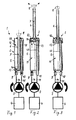
- Fig. 1 a section through a Hubdüse in a headlight cleaning system with a controllable pump, which is connected to two flow openings in the housing of the Hubdüse, wherein the promotion of fluid in the respective flow opening is adjustable, with an axially telescopically adjustable nozzle tube in the housing of the Hubdüse, shown in the withdrawn inoperative position,
- Fig. 2 the lifting nozzle in the operating position with the nozzle tube extended, through which fluid can escape
- Fig. 3 the lifting nozzle at the beginning of the transfer movement from the operating position back to the retracted inoperative position, which is performed by reversing the conveying direction of the fluid
- the headlight cleaning system 1 includes a Hubdüse 2, a pump 3 and a reservoir 4.
- the headlight cleaning system 1 is intended for use in a motor vehicle for cleaning the headlights, with basically also alternative applications for the cleaning system or the Hubdüse 2 come into consideration.
- the Hubdüse 2 has an advantageously cylindrical housing 5, in which a nozzle tube 6 is held axially translationally adjustable in the manner of a telescope. Inside the nozzle tube 6 there is a flow channel 7, on the front side of a nozzle head 8 is arranged, via which the Cleaning fluid emerges.
- the nozzle tube 6 is between the in Fig. 1 shown, withdrawn inoperative position and the in Fig. 2 adjusted, extended operating position to adjust. In the inoperative position, the nozzle tube is completely retracted into the interior of the housing 5, only the nozzle head 8 protrudes from the housing. In the operating position, however, the nozzle tube 6 is almost completely extended out of the housing.
- a partition wall 13 Integral with the nozzle tube 6 is a partition wall 13, which is held at the lower, first and second flow openings 9 and 10 in the housing wall adjacent side of the nozzle tube 6 and fills the interior of the housing.
- the partition 13 separates a first pressure chamber 11 from a second pressure chamber 12, wherein the first pressure chamber 11 communicates with the first flow opening 9 and the second pressure chamber 12 with the second flow opening 10.
- the two flow openings 9 and 10 are connected via lines 14 and 15 to the pump 3, wherein depending on the conveying direction of the pump 3 fluid is introduced via the opening 9 and discharged through the opening 10 or a flow in the opposite direction.
- This second pressure chamber 12 is connected to the second flow opening 10 via a connecting tube 17, which is guided in the interior of the housing 5. Fluid, which is located in the second pressure chamber 12, can thus escape during a Ausschubterrorism the nozzle tube 6 from the second pressure chamber 12 and via the connecting pipe 17 via the second flow opening 10 and the line 15.
- a transversely to the extension direction of the nozzle tube extending connecting channel 16 is introduced.
- the one mouth opening of the connecting channel 16 abuts against the inner wall of the housing 5 and is thereby closed.
- the opposite mouth opening of the connecting channel 16 opens into the flow channel 7, which in the Nozzle tube 6 runs.
- the opening on the inner wall of the connection channel 16 passes into the region of a bypass 18, which is introduced as a radial extension in the inner wall of the housing 5.
- the mouth opening of the connecting channel 16 is released and the fluid located in the first pressure chamber 11 can flow via the bypass 18 into the connecting channel 16 and further into the flow channel 7 and via the nozzle head 8, as in FIG Fig. 2 shown, emerge.
- the second pressure chamber 12 assumes its minimum size, a further flow outflow from the second pressure chamber 12 does not take place, since the second pressure chamber 12 is not reduced further.
- Fig. 3 the lifting nozzle 2 is shown at the beginning of the return movement from the operating position to the inoperative position.
- This return movement is carried out by means of the pump 3 by reversing the conveying direction of the pump 3 and conveying fluid via the second line 15 and the second flow opening 10 into the second pressure chamber 12.
- the partition wall 13 is thereby pressed in the direction of the bottom of the housing with the flow openings 9 and 10, whereby the nozzle tube 6 is retracted again.
- the fluid, which is located in the first pressure chamber 11, is derived by the reduction of the first pressure chamber via the first flow opening 9 and the line 14.
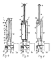
- the Hubdüse 2 the same structure as in the first embodiment, so that reference may be made to the description there.
- a switching valve 19 is assigned, which is upstream of the Hubdüse 2 and is operated by an actuator 20.
- the switching valve 19 is designed as a 4/2-way valve and connected to the two flow openings 9 and 10 in the housing 5 of the Hubdüse 2.
- the flow can be adjusted in the housing interior of the Hubdüse 2 optionally via the flow opening 9 or the flow opening 10, wherein the supply to the switching valve 19 regardless of the derivative of the switching valve in one of the flow openings 9 and 10 always over a same flow port 21 takes place, whereas the return is always performed via a second flow port 22.
- This allows the use of a simply constructed, so-called mono-pump, in which no reversal of the direction of rotation of the electric pump motor is required.
- the control of the flow supply either in the first or in the second flow opening 9 and 10 takes place solely via an adjustment of the switching valve 19 by means of the actuator 20.
Landscapes
- Engineering & Computer Science (AREA)
- Water Supply & Treatment (AREA)
- Mechanical Engineering (AREA)
- Lighting Device Outwards From Vehicle And Optical Signal (AREA)
- Nozzles (AREA)
Abstract
Description
Die Erfindung bezieht sich auf eine Hubdüse, insbesondere in einer Scheinwerferreinigungsanlage in einem Kraftfahrzeug, nach dem Oberbegriff des Anspruches 1.The invention relates to a lifting nozzle, in particular in a headlight cleaning system in a motor vehicle, according to the preamble of claim 1.
In der
Das Zurückverfahren des Düsenrohrs aus der ausgelenkten Betriebsposition in die zurückgezogene Außerbetriebsposition erfolgt üblicherweise durch die Kraft einer vorgespannten Feder, die das Düsenrohr in die Außerbetriebsposition kraftbeaufschlagt. Dieser Federdruck muss allerdings beim Ausfahren des Düsenrohrs von dem Wasserdruck überwunden werden, was einen verhältnismäßig hohen Druck voraussetzt. Dieser hohe Druck muss außerdem während des gesamten Betriebszeitraumes aufrechterhalten werden, während dem das Wasser über den Düsenkanal im Düsenrohr austritt. Um sicherzustellen, dass das Düsenrohr wieder in die Außerbetriebsposition verfährt, muss die Feder mit verhältnismäßig hoher Federkraft ausgelegt sein. Dies setzt auch eine entsprechende Dimensionierung der das Fluid fördernden Pumpe und der Leitungen voraus.The backward movement of the nozzle tube from the deflected operating position to the retracted inoperative position is usually accomplished by the force of a biased spring which urges the nozzle tube to the inoperative position. However, this spring pressure must when extending the nozzle tube of the Water pressure to be overcome, which requires a relatively high pressure. This high pressure must also be maintained throughout the operating period during which the water exits through the nozzle channel in the nozzle tube. To ensure that the nozzle tube moves back to the inoperative position, the spring must be designed with relatively high spring force. This also requires a corresponding dimensioning of the fluid pump and the pipes.
Der Erfindung liegt die Aufgabe zugrunde, eine Hubdüse mit einem Düsenrohr anzugeben, das mit einfachen konstruktiven Maßnahmen zwischen einer zurückgezogenen Außerbetriebsposition und einer ausgefahrenen Betriebsposition verstellbar ist. Auf den Einsatz einer Feder zum Rückholen des Düsenrohrs von der Betriebsposition in die Außerbetriebsposition soll gegebenenfalls verzichtet werden können.The invention has for its object to provide a Hubdüse with a nozzle tube, which is adjustable with simple constructive measures between a retracted inoperative position and an extended operating position. On the use of a spring for retrieving the nozzle tube from the operating position to the inoperative position should optionally be waived.
Diese Aufgabe wird erfindungsgemäß mit den Merkmalen des Anspruches 1 gelöst. Die Unteransprüche geben zweckmäßige Weiterbildungen an.This object is achieved with the features of claim 1. The dependent claims indicate expedient developments.
Die erfindungsgemäße Hubdüse, die insbesondere in einer Scheinwerferreinigungsanlage in einem Kraftfahrzeug zum Einsatz kommt, weist in einem Gehäuse ein verstellbar angeordnetes Düsenrohr mit einem darin verlaufenden Düsen- bzw. Strömungskanal für ein Fluid auf, insbesondere für Reinigungswasser. Dieses Düsenrohr ist durch den Druck des Fluids von der Außerbetriebsposition in die Betriebsposition verstellbar, und zwar in der Weise, dass in der Außerbetriebsposition das Fluid in einen ersten Druckraum im Gehäuse eintritt und das Düsenrohr in Richtung der Betriebsposition beaufschlagt. In der Betriebsposition kommuniziert der erste Druckraum mit dem Strömungskanal im Düsenraum, so dass das Fluid über den ersten Druckraum in den Strömungskanal im Düsenrohr eintreten und aus dem Düsenrohr ausgespritzt werden kann.The Hubdüse invention, which is used in particular in a headlight cleaning system in a motor vehicle, has in a housing an adjustable nozzle tube arranged therein with a nozzle or flow channel for a fluid, in particular for cleaning water. This nozzle tube is through the Pressure of the fluid from the inoperative position adjustable to the operating position, in such a manner that in the inoperative position, the fluid enters a first pressure chamber in the housing and acts on the nozzle tube in the direction of the operating position. In the operating position, the first pressure chamber communicates with the flow channel in the nozzle chamber, so that the fluid can enter the flow channel in the nozzle tube via the first pressure chamber and can be ejected from the nozzle tube.
Des Weiteren ist im Gehäuse ein vom ersten Druckraum separat ausgebildeter, zweiter Druckraum vorgesehen, in den ebenfalls Fluid einfüllbar ist, wobei das in den zweiten Druckraum eingeströmte Fluid das Düsenrohr aus der Betriebsposition in Richtung der Außerbetriebsposition beaufschlagt. Hierdurch ist es möglich, beide Stellbewegungen des Düsenrohres, also sowohl von der Außerbetriebsposition in die Betriebsposition als auch in umgekehrter Richtung, allein über den von dem Fluid erzeugten Druck durchzuführen. Weitere aktive oder passive Stellglieder wie z.B. Federelemente können zwar grundsätzlich zur Unterstützung der Rückholbewegung vorgesehen sein, sie sind aber nicht zwingend erforderlich. Die Bewegung des Düsenrohrs sowohl in die Betriebsposition als auch wieder zurück in die Außerbetriebsposition kann grundsätzlich allein über den Fluiddruck durchgeführt werden.Furthermore, a second pressure chamber formed separately from the first pressure chamber is provided in the housing, into which fluid can also be introduced, wherein the fluid flowed into the second pressure chamber acts on the nozzle tube from the operating position in the direction of the inoperative position. This makes it possible to perform both adjusting movements of the nozzle tube, so both from the inoperative position to the operating position and in the reverse direction, solely on the pressure generated by the fluid. Although more active or passive actuators such as spring elements can be provided in principle to support the return movement, but they are not mandatory. The movement of the nozzle tube both into the operating position and back to the inoperative position can in principle be carried out solely via the fluid pressure.
Gemäß zweckmäßiger Ausführung ist vorgesehen, dass der erste und der zweite Druckraum im Gehäuse der Hubdüse jeweils mit einer zugeordneten ersten bzw. zweiten Strömungsöffnung im Gehäuse verbunden ist, über die dem jeweils zugeordneten Druckraum Fluid zuführbar bzw. aus diesem ableitbar ist. Diese Strömungsöffnungen im Gehäuse können mit entsprechenden Strömungsleitungen einer Pumpe verbunden werden, wobei je nach Förderrichtung der Pumpe Fluid in den ersten bzw. zweiten Druckraum eingeleitet und, sofern erforderlich, zugleich aus dem jeweils anderen Druckraum abgeleitet wird. Dadurch ist sichergestellt, dass bei einer Bewegung des Düsenrohres das Fluid aus dem sich jeweils verkleinernden Druckraum abströmen kann.According to an expedient embodiment it is provided that the first and the second pressure chamber in the housing of the Hubdüse is respectively connected to an associated first or second flow opening in the housing, via which the respective associated pressure chamber fluid can be supplied or derived from this. These flow openings in the housing can be connected to corresponding flow lines of a pump, wherein depending on the conveying direction of the pump fluid is introduced into the first and second pressure chamber and, if necessary, at the same time derived from the respective other pressure chamber. This ensures that during a movement of the nozzle tube, the fluid can flow out of the respectively decreasing pressure chamber.
Die Druckräume sind zweckmäßigerweise über eine Trennwand oder dergleichen separiert, die fest mit dem Düsenrohr verbunden ist und eine Drucktrennung zwischen den Druckräumen sicherstellt. Das in den jeweiligen Druckraum einströmende Fluid beaufschlagt die Trennwand mit einer verstellenden Kraft zur Verstellung des Düsenrohres in die gewünschte Richtung.The pressure chambers are expediently separated by a partition or the like, which is firmly connected to the nozzle tube and ensures a pressure separation between the pressure chambers. The fluid flowing into the respective pressure chamber acts on the dividing wall with an adjusting force for adjusting the nozzle tube in the desired direction.
Bei der Verstellbewegung des Düsenrohres handelt es sich insbesondere um eine ausschließlich translatorische Stellbewegung im Sinne einer Teleskopbewegung. Grundsätzlich kommen aber auch rotatorische oder gemischt translatorisch-rotatorische Stellbewegungen bei der Überführung zwischen Außerbetriebs- und Betriebsposition in Betracht.The adjusting movement of the nozzle tube is in particular an exclusively translatory adjusting movement in the sense of a telescopic movement. In principle, however, also rotational or mixed translational-rotary actuating movements in the transfer between inoperative and operating position come into consideration.
Vorteilhafterweise wird der Strömungskanal in dem Düsenrohr, über den das Fluid austritt, mit dem Erreichen der Betriebsposition mit dem ersten Druckraum, in den das Fluid zur Ausübung der Verstellbewegung des Düsenrohres eintritt, zusammengeschaltet, so dass bei weiterer Druckbeaufschlagung nach Beendigung der Verstellbewegung in Richtung Betriebsposition das Fluid aus dem ersten Druckraum in den Strömungskanal im Düsenrohr einströmt und das Düsenrohr über die Mündungsöffnung verlässt. Die Kommunikationsverbindung zwischen erstem Druckraum und Strömungskanal im Düsenrohr wird vorzugsweise erst mit dem Erreichen der Betriebsposition freigeschaltet. Gemäß alternativer Ausführung kann es aber auch zweckmäßig sein, bereits vor Erreichen der Endposition die Strömungsverbindung freizugeben, so dass bereits während der Elongationsbewegung des Düsenrohres Fluid aus diesem austritt.Advantageously, the flow channel in the nozzle tube through which the fluid exits, with the achievement of the operating position with the first pressure chamber, in which the fluid for performing the adjustment of the nozzle tube enters interconnected, so that upon further pressurization after completion of the adjustment in the direction of operating position the fluid from the first pressure chamber flows into the flow channel in the nozzle tube and leaves the nozzle tube via the mouth opening. The communication connection between the first pressure chamber and the flow channel in the nozzle tube is preferably released only when the operating position has been reached. According to an alternative embodiment, however, it may also be expedient to release the flow connection even before reaching the end position, so that fluid already exits from it during the elongation movement of the nozzle tube.
Gemäß einer weiteren Alternative erfolgt die Einleitung des Fluids in den Strömungskanal im Düsenrohr nicht über den ersten Druckraum, sondern über eine zusätzliche Strömungsverbindung, die in das Gehäuse der Hubdüse eingebracht ist.According to a further alternative, the introduction of the fluid into the flow channel in the nozzle tube is not via the first pressure chamber, but via an additional flow connection, which is introduced into the housing of the Hubdüse.
Die Verbindung zwischen dem ersten Druckraum und dem Strömungskanal im Düsenrohr erfolgt vorteilhafterweise über einen Verbindungskanal, der in der Betriebsposition des Düsenrohrs freigegeben ist und insbesondere in die Trennwand zwischen den beiden Druckräumen eingebracht ist, welche fest mit dem Düsenrohr verbunden ist und die gleiche Stellbewegung wie das Düsenrohr ausübt. Sofern erst mit Erreichen der endgültigen Betriebsposition Fluid aus dem Düsenrohr austreten soll, wird dieser Verbindungskanal auch erst mit Erreichen dieser Endstellung des Düsenrohres in Kommunikation mit dem ersten Druckraum geschaltet; vor dem Erreichen der Betriebsposition ist dagegen der Verbindungskanal vom Druckraum abgeschnitten. Konstruktiv kann dies dadurch realisiert werden, dass der Verbindungskanal quer zur Verstellrichtung des Düsenrohres verläuft, wobei eine Mündungsöffnung des Verbindungskanals in Außerbetriebsposition an der Innenwand des Gehäuses anliegt und dadurch verschlossen ist, wohingegen in der Betriebsposition diese Mündungsöffnung in Kommunikation mit einem in die Innenwand des Gehäuses eingebrachten Bypass gelangt, über den das Fluid aus dem ersten Druckraum in den Verbindungskanal einströmen kann.The connection between the first pressure chamber and the flow channel in the nozzle tube is advantageously via a connecting channel which is released in the operating position of the nozzle tube and in particular in the partition wall between the two pressure chambers is introduced, which is fixedly connected to the nozzle tube and exerts the same adjusting movement as the nozzle tube. If fluid is to escape from the nozzle tube only when the final operating position has been reached, this connecting channel is also switched into communication with the first pressure chamber only when this end position of the nozzle tube is reached; before reaching the operating position, however, the connecting channel is cut off from the pressure chamber. This can be realized constructively in that the connecting channel extends transversely to the adjustment direction of the nozzle tube, wherein an outlet opening of the connecting channel in non-operating position abuts against the inner wall of the housing and is thereby closed, whereas in the operating position, this orifice in communication with a in the inner wall of the housing introduced bypass passes, through which the fluid from the first pressure chamber can flow into the connecting channel.
Die Hubdüse ist vorteilhafterweise Bestandteil einer Scheinwerferreinigungsanlage in einem Kraftfahrzeug, die mit einer Pumpe zur Förderung des Fluids wahlweise in den ersten oder in den zweiten Druckraum versehen ist. Bei dieser Pumpe kommen verschiedene Ausführungen in Betracht; möglich ist beispielsweise eine Pumpe mit einem Schaltventil, über dessen Position der von der Pumpe geförderte Fluidstrom wahlweise in die erste oder in die zweite Strömungsöffnung im Gehäuse gefördert wird. Bei dieser Ausführung können einfach aufgebaute, so genannte Monopumpen mit gleichbleibender Motordrehrichtung eingesetzt werden.The Hubdüse is advantageously part of a headlight cleaning system in a motor vehicle, which is provided with a pump for conveying the fluid optionally in the first or in the second pressure chamber. In this pump, different versions are possible; possible, for example, a pump with a switching valve, via the position of the pumped by the pump fluid flow either in the first or in the second flow opening in Housing is promoted. In this design, simply constructed, so-called monopumps with the same direction of motor rotation can be used.
Alternativ ist aber auch die Verwendung einer Dualpumpe möglich, die ohne ein derartiges Schaltventil direkt mit den beiden Strömungsöffnungen im Gehäuse verbunden ist, wobei die Fluidförderung in die erste oder in die zweite Strömungsöffnung über die Drehrichtung des Pumpenmotors der Dualpumpe gesteuert wird.Alternatively, however, the use of a dual pump is possible, which is connected without such a switching valve directly to the two flow openings in the housing, wherein the fluid delivery is controlled in the first or in the second flow opening on the direction of rotation of the pump motor of the dual pump.
Weitere Vorteile und zweckmäßige Ausführungen sind den weiteren Ansprüchen, der Figurenbeschreibung und den Zeichnungen zu entnehmen. Es zeigen:Further advantages and expedient embodiments can be taken from the further claims, the description of the figures and the drawings. Show it:
In den Figuren sind gleiche Bauteile mit gleichen Bezugszeichen versehen.In the figures, the same components are provided with the same reference numerals.
Wie in
Aus dem Vorratsbehälter 4 wird Fluid, insbesondere Wasser, mittels der Pumpe 3 in die Hubdüse 2 gefördert. Die Hubdüse 2 weist ein vorteilhaft zylindrisches Gehäuse 5 auf, in welchem ein Düsenrohr 6 axial translatorisch verstellbar nach Art eines Teleskopes gehalten ist. Im Inneren des Düsenrohres 6 befindet sich ein Strömungskanal 7, an dessen Stirnseite ein Düsenkopf 8 angeordnet ist, über den das Reinigungsfluid austritt. Das Düsenrohr 6 ist zwischen der in
Einteilig mit dem Düsenrohr 6 ist eine Trennwand 13 ausgebildet, die an den unteren, ersten und zweiten Strömungsöffnungen 9 und 10 in der der Gehäusewand benachbarten Seite des Düsenrohres 6 gehalten ist und den Innenraum des Gehäuses ausfüllt. Die Trennwand 13 separiert einen ersten Druckraum 11 von einem zweiten Druckraum 12, wobei der erste Druckraum 11 mit der ersten Strömungsöffnung 9 und der zweite Druckraum 12 mit der zweiten Strömungsöffnung 10 kommuniziert. Die beiden Strömungsöffnungen 9 und 10 sind über Leitungen 14 und 15 mit der Pumpe 3 verbunden, wobei je nach Förderrichtung der Pumpe 3 Fluid über die Öffnung 9 eingeleitet und über die Öffnung 10 ausgeleitet wird oder eine Durchströmung in Gegenrichtung erfolgt.Integral with the
Wie einem Vergleich der
In die Trennwand 13 ist ein quer zur Ausschubrichtung des Düsenrohrs verlaufender Verbindungskanal 16 eingebracht. Während der Überführungsbewegung von der zurückgezogenen Außerbetriebsposition in die ausgelenkte Betriebsposition liegt die eine Mündungsöffnung des Verbindungskanals 16 an der Innenwand des Gehäuses 5 an und ist dadurch verschlossen. Die gegenüberliegende Mündungsöffnung des Verbindungskanals 16 mündet in den Strömungskanal 7, der im Düsenrohr 6 verläuft. Mit Erreichen der Betriebsposition (
In
Im zweiten Ausführungsbeispiel gemäß den
Claims (10)
Applications Claiming Priority (1)
| Application Number | Priority Date | Filing Date | Title |
|---|---|---|---|
| DE202007003861U DE202007003861U1 (en) | 2007-03-13 | 2007-03-13 | Hubdüse, especially in a headlight cleaning system |
Publications (2)
| Publication Number | Publication Date |
|---|---|
| EP1970269A2 true EP1970269A2 (en) | 2008-09-17 |
| EP1970269A3 EP1970269A3 (en) | 2010-12-15 |
Family
ID=39468795
Family Applications (1)
| Application Number | Title | Priority Date | Filing Date |
|---|---|---|---|
| EP08102569A Withdrawn EP1970269A3 (en) | 2007-03-13 | 2008-03-13 | Telescopic nozzle, particularly in a headlight cleaning device |
Country Status (2)
| Country | Link |
|---|---|
| EP (1) | EP1970269A3 (en) |
| DE (2) | DE202007003861U1 (en) |
Cited By (2)
| Publication number | Priority date | Publication date | Assignee | Title |
|---|---|---|---|---|
| EP3121070A1 (en) * | 2015-07-22 | 2017-01-25 | Valeo Systèmes d'Essuyage | Sensor cleaning device for a motor vehicle |
| EP3318452A1 (en) * | 2016-11-07 | 2018-05-09 | Fico Transpar, S.A. | Fluid-ejection device |
Families Citing this family (2)
| Publication number | Priority date | Publication date | Assignee | Title |
|---|---|---|---|---|
| DE202008012729U1 (en) * | 2008-09-24 | 2010-02-25 | Mann+Hummel Gmbh | Hubdüse in a cleaning system in a motor vehicle |
| DE102021117688A1 (en) | 2021-07-08 | 2023-01-12 | Webasto SE | Roof module for forming a vehicle roof with a lockable cleaning nozzle |
Citations (2)
| Publication number | Priority date | Publication date | Assignee | Title |
|---|---|---|---|---|
| BG27569A1 (en) * | 1978-10-30 | 1979-12-12 | Georgiev | Telescopic sinking hydrant |
| DE19918759A1 (en) | 1999-04-24 | 2000-10-26 | Volkswagen Ag | Headlight cleaning system for a motor vehicle |
Family Cites Families (8)
| Publication number | Priority date | Publication date | Assignee | Title |
|---|---|---|---|---|
| US3263929A (en) * | 1964-10-28 | 1966-08-02 | Seablom Wendell | Sprinkler head and system |
| DE2154522A1 (en) * | 1971-11-03 | 1973-05-10 | Juergen Eissmann | DEVICE FOR CLEANING SURFACES, ESPECIALLY ON LIGHTING SYSTEMS OF MOTOR VEHICLES |
| BG26010A1 (en) * | 1978-04-13 | 1982-12-15 | Georgiev | Sinking hydrant |
| JPS62261693A (en) * | 1986-04-30 | 1987-11-13 | Maruko Keihouki Kk | Selective type delivery pump |
| DE3708327A1 (en) * | 1987-03-14 | 1988-09-22 | Bosch Gmbh Robert | DEVICE FOR CONVEYING LIQUID ON TWO SPRAY NOZZLES DISC AREAS OF A MOTOR VEHICLE |
| FR2703409B1 (en) * | 1993-04-02 | 1995-06-02 | Seim Ind | Bi-directional centrifugal pump. |
| FR2738203B1 (en) * | 1995-08-31 | 1997-09-26 | Valeo Systemes Dessuyage | THREE-WAY WASHING LIQUID SPRAYING DEVICE FOR A MOTOR VEHICLE |
| DE10052828A1 (en) * | 2000-10-24 | 2002-05-29 | Siemens Ag | Cleaning plant and method for operating the same |
-
2007
- 2007-03-13 DE DE202007003861U patent/DE202007003861U1/en not_active Expired - Lifetime
-
2008
- 2008-03-13 EP EP08102569A patent/EP1970269A3/en not_active Withdrawn
- 2008-07-15 DE DE102008033218A patent/DE102008033218A1/en not_active Withdrawn
Patent Citations (3)
| Publication number | Priority date | Publication date | Assignee | Title |
|---|---|---|---|---|
| BG27569A1 (en) * | 1978-10-30 | 1979-12-12 | Georgiev | Telescopic sinking hydrant |
| DE2918922A1 (en) * | 1978-10-30 | 1980-05-14 | Inst Mekhaniki Biomekh | FOLDABLE TELESCOPHYDRANT |
| DE19918759A1 (en) | 1999-04-24 | 2000-10-26 | Volkswagen Ag | Headlight cleaning system for a motor vehicle |
Cited By (6)
| Publication number | Priority date | Publication date | Assignee | Title |
|---|---|---|---|---|
| EP3121070A1 (en) * | 2015-07-22 | 2017-01-25 | Valeo Systèmes d'Essuyage | Sensor cleaning device for a motor vehicle |
| FR3039113A1 (en) * | 2015-07-22 | 2017-01-27 | Valeo Systemes Dessuyage | DEVICE FOR CLEANING A SENSOR FOR A MOTOR VEHICLE |
| CN106427895A (en) * | 2015-07-22 | 2017-02-22 | 法雷奥系统公司 | Sensor cleaning device for a motor vehicle |
| CN106427895B (en) * | 2015-07-22 | 2019-12-24 | 法雷奥系统公司 | Sensor cleaning device for motor vehicles |
| US10569747B2 (en) | 2015-07-22 | 2020-02-25 | Valeo Systèmes d'Essuyage | Sensor cleaning device for a motor vehicle |
| EP3318452A1 (en) * | 2016-11-07 | 2018-05-09 | Fico Transpar, S.A. | Fluid-ejection device |
Also Published As
| Publication number | Publication date |
|---|---|
| DE102008033218A1 (en) | 2010-04-01 |
| DE202007003861U1 (en) | 2008-07-17 |
| EP1970269A3 (en) | 2010-12-15 |
Similar Documents
| Publication | Publication Date | Title |
|---|---|---|
| EP2683645B1 (en) | Boom of a loading crane | |
| EP1854558B1 (en) | Valve assembly | |
| EP1970269A2 (en) | Telescopic nozzle, particularly in a headlight cleaning device | |
| WO2016150569A1 (en) | Valve and cleaning device for a motor vehicle | |
| EP2835540B1 (en) | Hydraulic drive | |
| DE1430724B2 (en) | Steering system for an articulated vehicle | |
| EP0514748A1 (en) | Device for restricting the stroke of a hydraulic cylinder | |
| EP2025978A2 (en) | Direction control valve for a windscreen cleaning device in a motor vehicle | |
| WO2022106168A1 (en) | Valve | |
| DE9218333U1 (en) | Hydraulic actuation arrangement for a vehicle top | |
| DE102007021381A1 (en) | Valve arrangement for e.g. high pressure washer, has actuating device and control device formed as modular component, where actuating device is decoupled from closing body of bypass valve and influence on valve with actuating force | |
| DE19844669A1 (en) | Hydrostatic drive system for mechanical excavator maximises operational reliability while minimising power losses | |
| EP3728864B1 (en) | Actuator with hydraulic drain amplifier | |
| EP1854557A2 (en) | Valve assembly | |
| DE19710983C2 (en) | check valve | |
| DE102004034280A1 (en) | Hydraulic cylinder, has pusher to feed fluid, which has been pushed out from rod side cylindrical space, additionally into base side cylindrical space when fluid is fed into base side space as soon as piston rod comes out of housing | |
| EP2550461B1 (en) | Device for locking an axially movable component of a hydraulic system | |
| WO2009109281A1 (en) | Hydraulic power steering | |
| WO2013060573A1 (en) | Valve device, in particular for controlling a pressure cutting valve | |
| DE102011119414B4 (en) | Flow divider | |
| DE102009042586A1 (en) | Hub nozzle for use in cleaning system i.e. headlight cleaning system, in motor vehicle, has clamping element lying in flow path of cleaning fluid and adjustable into position that reduces clamping force by pressure of cleaning fluid | |
| DE102007021379A1 (en) | High pressure water gun, for cleaning surfaces by water jet blasting, has a valve assembly with a bypass valve to return water to the tank when the gun valve is closed | |
| DE102010023015B4 (en) | Hydraulic system | |
| EP2674626B1 (en) | Hydraulic circuit | |
| EP4596123A1 (en) | Valve assembly and method for producing a valve assembly |
Legal Events
| Date | Code | Title | Description |
|---|---|---|---|
| PUAI | Public reference made under article 153(3) epc to a published international application that has entered the european phase |
Free format text: ORIGINAL CODE: 0009012 |
|
| AK | Designated contracting states |
Kind code of ref document: A2 Designated state(s): AT BE BG CH CY CZ DE DK EE ES FI FR GB GR HR HU IE IS IT LI LT LU LV MC MT NL NO PL PT RO SE SI SK TR |
|
| AX | Request for extension of the european patent |
Extension state: AL BA MK RS |
|
| PUAL | Search report despatched |
Free format text: ORIGINAL CODE: 0009013 |
|
| AK | Designated contracting states |
Kind code of ref document: A3 Designated state(s): AT BE BG CH CY CZ DE DK EE ES FI FR GB GR HR HU IE IS IT LI LT LU LV MC MT NL NO PL PT RO SE SI SK TR |
|
| AX | Request for extension of the european patent |
Extension state: AL BA MK RS |
|
| RIC1 | Information provided on ipc code assigned before grant |
Ipc: B05B 15/10 20060101ALI20101110BHEP Ipc: B60S 1/52 20060101AFI20080612BHEP |
|
| 17P | Request for examination filed |
Effective date: 20110131 |
|
| AKX | Designation fees paid |
Designated state(s): AT BE BG CH CY CZ DE DK EE ES FI FR GB GR HR HU IE IS IT LI LT LU LV MC MT NL NO PL PT RO SE SI SK TR |
|
| RIC1 | Information provided on ipc code assigned before grant |
Ipc: B05B 15/10 20060101ALI20150223BHEP Ipc: B60S 1/52 20060101AFI20150223BHEP |
|
| GRAP | Despatch of communication of intention to grant a patent |
Free format text: ORIGINAL CODE: EPIDOSNIGR1 |
|
| INTG | Intention to grant announced |
Effective date: 20150408 |
|
| STAA | Information on the status of an ep patent application or granted ep patent |
Free format text: STATUS: THE APPLICATION IS DEEMED TO BE WITHDRAWN |
|
| 18D | Application deemed to be withdrawn |
Effective date: 20150819 |