EP1970258A1 - Ventilating member and ventilating structure - Google Patents
Ventilating member and ventilating structure Download PDFInfo
- Publication number
- EP1970258A1 EP1970258A1 EP06811704A EP06811704A EP1970258A1 EP 1970258 A1 EP1970258 A1 EP 1970258A1 EP 06811704 A EP06811704 A EP 06811704A EP 06811704 A EP06811704 A EP 06811704A EP 1970258 A1 EP1970258 A1 EP 1970258A1
- Authority
- EP
- European Patent Office
- Prior art keywords
- support body
- gas permeable
- housing
- permeable membrane
- vent member
- Prior art date
- Legal status (The legal status is an assumption and is not a legal conclusion. Google has not performed a legal analysis and makes no representation as to the accuracy of the status listed.)
- Withdrawn
Links
Images


Classifications
-
- B—PERFORMING OPERATIONS; TRANSPORTING
- B60—VEHICLES IN GENERAL
- B60R—VEHICLES, VEHICLE FITTINGS, OR VEHICLE PARTS, NOT OTHERWISE PROVIDED FOR
- B60R16/00—Electric or fluid circuits specially adapted for vehicles and not otherwise provided for; Arrangement of elements of electric or fluid circuits specially adapted for vehicles and not otherwise provided for
- B60R16/02—Electric or fluid circuits specially adapted for vehicles and not otherwise provided for; Arrangement of elements of electric or fluid circuits specially adapted for vehicles and not otherwise provided for electric constitutive elements
-
- F—MECHANICAL ENGINEERING; LIGHTING; HEATING; WEAPONS; BLASTING
- F21—LIGHTING
- F21V—FUNCTIONAL FEATURES OR DETAILS OF LIGHTING DEVICES OR SYSTEMS THEREOF; STRUCTURAL COMBINATIONS OF LIGHTING DEVICES WITH OTHER ARTICLES, NOT OTHERWISE PROVIDED FOR
- F21V31/00—Gas-tight or water-tight arrangements
- F21V31/03—Gas-tight or water-tight arrangements with provision for venting
-
- B—PERFORMING OPERATIONS; TRANSPORTING
- B65—CONVEYING; PACKING; STORING; HANDLING THIN OR FILAMENTARY MATERIAL
- B65D—CONTAINERS FOR STORAGE OR TRANSPORT OF ARTICLES OR MATERIALS, e.g. BAGS, BARRELS, BOTTLES, BOXES, CANS, CARTONS, CRATES, DRUMS, JARS, TANKS, HOPPERS, FORWARDING CONTAINERS; ACCESSORIES, CLOSURES, OR FITTINGS THEREFOR; PACKAGING ELEMENTS; PACKAGES
- B65D81/00—Containers, packaging elements, or packages, for contents presenting particular transport or storage problems, or adapted to be used for non-packaging purposes after removal of contents
- B65D81/24—Adaptations for preventing deterioration or decay of contents; Applications to the container or packaging material of food preservatives, fungicides, pesticides or animal repellants
- B65D81/26—Adaptations for preventing deterioration or decay of contents; Applications to the container or packaging material of food preservatives, fungicides, pesticides or animal repellants with provision for draining away, or absorbing, or removing by ventilation, fluids, e.g. exuded by contents; Applications of corrosion inhibitors or desiccators
-
- H—ELECTRICITY
- H05—ELECTRIC TECHNIQUES NOT OTHERWISE PROVIDED FOR
- H05K—PRINTED CIRCUITS; CASINGS OR CONSTRUCTIONAL DETAILS OF ELECTRIC APPARATUS; MANUFACTURE OF ASSEMBLAGES OF ELECTRICAL COMPONENTS
- H05K5/00—Casings, cabinets or drawers for electric apparatus
- H05K5/02—Details
- H05K5/0213—Venting apertures; Constructional details thereof
- H05K5/0215—Venting apertures; Constructional details thereof with semi-permeable membranes attached to casings
-
- F—MECHANICAL ENGINEERING; LIGHTING; HEATING; WEAPONS; BLASTING
- F21—LIGHTING
- F21S—NON-PORTABLE LIGHTING DEVICES; SYSTEMS THEREOF; VEHICLE LIGHTING DEVICES SPECIALLY ADAPTED FOR VEHICLE EXTERIORS
- F21S45/00—Arrangements within vehicle lighting devices specially adapted for vehicle exteriors, for purposes other than emission or distribution of light
- F21S45/30—Ventilation or drainage of lighting devices
-
- F—MECHANICAL ENGINEERING; LIGHTING; HEATING; WEAPONS; BLASTING
- F24—HEATING; RANGES; VENTILATING
- F24F—AIR-CONDITIONING; AIR-HUMIDIFICATION; VENTILATION; USE OF AIR CURRENTS FOR SCREENING
- F24F3/00—Air-conditioning systems in which conditioned primary air is supplied from one or more central stations to distributing units in the rooms or spaces where it may receive secondary treatment; Apparatus specially designed for such systems
- F24F3/12—Air-conditioning systems in which conditioned primary air is supplied from one or more central stations to distributing units in the rooms or spaces where it may receive secondary treatment; Apparatus specially designed for such systems characterised by the treatment of the air otherwise than by heating and cooling
- F24F3/14—Air-conditioning systems in which conditioned primary air is supplied from one or more central stations to distributing units in the rooms or spaces where it may receive secondary treatment; Apparatus specially designed for such systems characterised by the treatment of the air otherwise than by heating and cooling by humidification; by dehumidification
- F24F2003/1435—Air-conditioning systems in which conditioned primary air is supplied from one or more central stations to distributing units in the rooms or spaces where it may receive secondary treatment; Apparatus specially designed for such systems characterised by the treatment of the air otherwise than by heating and cooling by humidification; by dehumidification comprising semi-permeable membrane
Definitions
- the present invention relates to a vent member attached to a housing that accommodates automobile components, electronic components or the like.
- the present invention also relates to a vent structure using the vent member.
- Housings that accommodate automobile electrical components such as lamps, sensors and ECUs (electronic control unit) have a vent member attached thereto to ensure ventilation between the interior and the exterior of the housing and to prevent foreign matter from intruding into the housing.
- a vent member is disclosed in JP 2004-47425A and JP 2003-336874A .
- a vent member disclosed in JP2004-47425A is, for example, provided with a support body 203 on which a gas permeable membrane 202 is disposed and a cover part 204 attached to the support body 203 so as to cover the gas permeable membrane 202, as shown in Fig. 13 .
- the vent member 201 thus configured is fixed to an opening portion 207 of a housing 206 via an O-ring 205. Gas is allowed to permeate through the gas permeable membrane 202 so that ventilation between the interior and the exterior of the housing 206 is ensured.
- the cover part 204 prevents the gas permeable membrane 202 from being damaged by an external force, and deteriorated in gas permeability due to the deposition of dust.
- the vent member shown in Fig. 13 can be attached to the opening portion of the housing with ease. Furthermore, the protrusion from an outer surface of the housing is relatively low. This seems to be preferable because the vent member occupies no excess space. However, intensive studies made by the inventor have found that this is not always the case.
- the gas permeable membrane of the vent member is close to the outer surface of the housing when the vent member is attached to the opening portion of the housing.
- the water droplets or the like possibly flow toward a surface of the gas permeable membrane easily along a side surface the support body to which the gas permeable membrane is fixed. This phenomenon becomes obvious when the water droplets or oil droplets remain around a boundary between the vent member and the housing and the atmospheric pressure inside the housing rapidly drops below the atmospheric pressure outside the housing.
- the present invention has an object to provide a vent member that can prevent water droplets or the like from flowing toward the gas permeable membrane even when the droplets adhere to the outer surface of the housing, and thereby can maintain gas permeability in a reliable manner.
- the present invention has another object to provide a vent structure using this vent member.
- the present invention provides a vent member to be attached to a housing that needs ventilation.
- the vent member includes a support body having a through hole to serve as a gas passage between the interior and the exterior of the housing and a gas permeable membrane fixed to the support body so as to close the through hole.
- a thickness direction of the gas permeable membrane is a height direction
- the support body is formed so that the through hole extends in the height direction from one opening end face to the other opening end face, and the height from the one opening end face to the other opening end face is set to 4 mm or more.
- the vent member includes a support body having a through hole to serve as a gas passage between the interior and the exterior of the housing, and a gas permeable membrane fixed to the support body so as to close the through hole.
- the support body includes a base portion to be connected to the housing. An area of the base portion defined by an outline of a lateral cross-section perpendicular to the thickness direction of the gas permeable membrane increases continuously or stepwise from the side on which the gas permeable membrane is disposed toward the side that is to be connected to the housing.
- vent member to be attached to a housing that needs ventilation.
- the vent member includes a support body having an interior space to serve as a gas passage between the interior and the exterior of the housing and an opening portion through which the interior space communicates with the exterior of the housing, and a gas permeable membrane fixed to the support body so as to close the opening portion.
- a thickness direction of the gas permeable membrane is a height direction
- one of the end faces of the support body in the height direction serves as a predetermined fixing surface that is to be fixed to the housing directly or via another member, and the height from the predetermined fixing surface to the end face on the other side on which the opening portion is formed is set to 4 mm or more.
- Still another aspect of the present invention provides a vent structure including a housing that needs ventilation and the above-mentioned vent member attached to an opening portion of the housing.
- the vent member (or the vent structure) of the present invention described above the height from the outer surface of the housing to the opening end face on the opposite side sufficiently is ensured as 4 mm or more. This makes it possible to prevent water droplets or the like from flowing onto the gas permeable membrane even when water droplets or the like remain in areas including a connection point between the vent member and the housing. In other words, it is possible to obtain a vent member that can maintain gas permeability in a reliable manner even when water droplets or the like adhere to the outer surface of the housing.
- the support body to which the gas permeable membrane is fixed, includes the base portion having a lateral cross-sectional area increasing continuously or stepwise toward the housing. According to such a structure, it becomes difficult for water droplets or the like to remain around the border between the vent member and the housing. As a result, it is possible to obtain a vent member that can prevent water droplets or the like from flowing onto the gas permeable membrane even when the water droplets or the like adhere to the outer surface of the housing, and thereby can maintain gas permeability in a reliable manner.
- Fig. 1A is a perspective view of a vent member of a first embodiment according to the present invention
- Fig. 1B is a sectional perspective view thereof.
- Fig. 12 is a general view of a housing on which the vent member of Fig. 1A is attached.
- the vent member 13A shown in Fig. 1A and 1B constitutes a vent structure 100A for providing ventilation between the interior and the exterior of a housing 91 when attached to an opening portion 91k of the housing 91 of, for example, an automobile electrical component.
- the housing is not limited to a box-shaped housing as shown in Fig. 12 . Any components or articles having an interior space that needs ventilation can be a housing to which the vent member of the present invention is to be attached.
- the vent member 13A is provided with a support body 11 having a through hole 11h to serve as a gas passage between the interior and the exterior of the housing 91 and a gas permeable membrane 6 disposed on the support body 11 so as to close one of the openings of the through hole 11h.
- the support body 11 is of an approximately circular cylindrical shape.
- the gas permeable membrane 6 of a circular shape is disposed on a first opening end face 11p, which is one of the opening end faces of the circular cylindrical support body 11.
- a diameter of the gas permeable membrane 6 is smaller than an outer diameter of the support body 11 and larger than an inner diameter of the support body 11 at the first opening end face 11p.
- the vent member 13A is fixed to the opening portion 91k of the housing 91 in such a manner that the through hole 11h of the support body 11, the gas permeable membrane 6 and the opening portion 91k of the housing 91 are arranged concentrically. That is, one of the openings of the through hole 11 formed in the support body 11 is closed by the gas permeable membrane 6 while the other opening opens toward the interior of the housing 91.
- the gas permeable membrane 6 allows a gas to permeate therethrough and prevents entry of foreign matter, such as water droplets and dust.
- the gas permeability of the gas permeable membrane 6 maintains the pressure inside of the housing 91 equal to the pressure outside of the housing.
- the support body 11 of the vent member 13A includes a cover 16 forming a clearance between the gas permeable membrane 6 and itself and covering the gas permeable membrane 6 on the side opposite to the side that is to be attached to the opening portion 91k of the housing 91.
- the first opening end face 11p and a second opening end face 11q which are the two opening end faces of the support body 11
- the first opening end face 11p located on the opposite side of the second opening end face 11q is covered with the cover 16.
- the clearance is formed between the first opening end face 11p and the cover 16, and it communicates with an opening 16h that opens in a direction parallel to an in-plane of the gas permeable membrane 6.
- the cover 16 is manufactured as a separate part from the support body 11 having the through hole 11h. The cover 16 is combined with the support body 11 after the gas permeable membrane 6 is fixed on the first opening end face 11p.
- the support body 11 as described above can be manufactured by popular molding techniques, such as injection molding, compression molding, and cutting. From the viewpoint of moldability, a thermoplastic resin is preferably used as a material for the support body 11. Specifically, thermoplastic resins such as PBT (polybutylene terephthalate), PA (nylon) and PET (polyethlene terephthalate), and thermoplastic elastomers such as EPDM (ethylene propylene rubber) and silicone rubber can be used.
- the materials for the support body 11 may include pigments such as carbon black and titanium white, reinforcement fillers such as glass particles and glass fibers, and water repellants. The support body 11 repels liquid (such as water and oil) more easily when applied with a liquid-repellent treatment on its surface. Other treatments for providing desired characteristics such as adhesiveness improvement, electrical insulation, semiconductivity, conductivity may be applied on the support body 11.
- the gas permeable membrane 6 is not particularly limited in terms of structure and material as long as it is a membrane that allows gas permeation while preventing liquid permeation.
- This embodiment describes the gas permeable membrane 6 formed by laminating a reinforcing layer on a resin porous membrane. More specifically, this embodiment describes the gas permeable membrane 6 with three layers (for example, TEMISH (registered trademark) available from Nitto Denko Corp.) formed by laminating a resin porous membrane on top and bottom of a reinforcing layer. With the reinforcing layer, the gas permeable membrane 6 is allowed to have a higher strength.
- TEMISH registered trademark
- a fluororesin porous body and a polyolefin porous body that can be manufactured by a known drawing method or extracting method can be used.
- the fluororesin include PTFE (polytetrafluoroethylene), polychlorotrifluoroethylene, tetrafluoroethylene-hexafluoropropylene copolymer, and tetrafluoroethylene-ethylene copolymer.
- the monomer of which the polyolefin is composed include ethylene, propylene and 4-methylpentene-1,1 butene. It is possible to use a polyolefin obtained by polymerizing these monomers independently or copolymerizing them.
- a nanofiber film porous body or the like using polyacrylonitrile, nylon and polylactate also can be used.
- a PTFE porous body is preferably used because it can ensure gas permeability even with a small area and prevent foreign matter from intruding into the housing in a highly effective manner.
- the liquid-repellent treatment may be applied to the resin porous membrane that forms the gas permeable membrane 6 in accordance with the application of the housing.
- the liquid-repellent treatment can be carried out by applying the resin porous membrane with a substance having small surface tension, drying the substance and then curing the substance.
- a liquid-repellent agent used for the liquid-repellent treatment is not particularly limited as long as it can form a coating having a surface tension lower than that of the resin porous membrane.
- a liquid-repellent agent containing polymers having perfluoroalkyl groups is suitable.
- the liquid-repellent agent may be applied by impregnation, spraying or the like. From the viewpoint of ensuring sufficient waterproofness, the average pore diameter of the resin porous membrane is preferably 0.01 ⁇ m or more and not more than 10 ⁇ m.
- the material of the reinforcing layer forming the gas permeable membrane 6 excels more in gas permeability than the resin porous membrane.
- a fabric, a nonwoven fabric, a mesh, a net, a sponge, a form, a porous body (Sunmap available from Nitto Denko Corp., for example) or the like can be used. These are made of resin or metal.
- the methods for bonding the resin porous membrane to the reinforcing layer include adhesive lamination, heat lamination, heat welding, laser welding, ultrasonic welding, and the use of an adhesive agent.
- the thickness of the gas permeable membrane 6 is set in the range of, for example, 1 ⁇ m to 5 mm, taking into account its strength and the ease of fixing to the support body 11.
- the gas permeability of the gas permeable membrane 6 is preferably in a rage of 0.1 to 300 sec/100 cm 3 in terms of Gurley value.
- a thickness direction of the gas permeable membrane 6 is assumed as a height direction in the descriptions hereinafter including other embodiments. It is also assumed that the surface of the gas permeable membrane 6 facing to the side of the housing 91 is an under surface while the surface on the opposite side is an upper surface.
- an outer surface 91p of the housing 91 surrounding the vent member 13A is a flat surface approximately parallel to a principal surface of the gas permeable membrane 6 in this embodiment
- the second opening end face 11q on the opposite side of the first opening end face 11p to which the gas 6 is fixed is a bonding surface that is directly bonded to the opening portion 91k of the housing 91.
- the through hole 11h is formed so as to extend almost linearly in the height direction from the second opening end face 11q to the first opening end face 11p.
- a height H 1 from the second opening end face 11q to the gas permeable membrane 6, in other words, a height H 1 from the outer surface 91p of the housing 91 surrounding the vent member 13A to the gas permeable membrane 6, is set to 4 mm or more.
- the height H 1 of 4 mm or more makes it difficult for the water droplets or the like adhering to the housing 91 to reach the gas permeable membrane 6 under normal conditions.
- the height H 1 is set preferably to 6 mm or more, further preferably to 10 mm or more, in order to prevent the water droplets or the like from contacting the gas permeable membrane 6 in a more reliable manner. It is desirable, however, that the height H 1 is 30 mm or less in order to avoid an excessive protrusion of the vent member 13A from the outer surface 91p of the housing 91. These dimensions apply to other embodiments to be described later.
- a method such as heat welding, ultrasonic welding, laser welding, the use of an adhesive tape, the use of an adhesive agent can be adopted for fixing the vent member 13A to the opening portion 91k of the housing 91.
- the height H 1 of the support body 11 from the outer surface 91p of the housing 91 to the under surface of the gas permeable membrane 6 is set to be smaller than the outer diameter of the support body 11 in a cross section perpendicular to the height direction. This makes it possible to obtain a sufficient stability when the vent member 13A is fixed to the opening portion 91k of the housing 91, and thereby reduce the possibility that the vent member 13A falls off the housing 91 when an impact is applied thereto by foreign matter or the like.
- Ribs 14, 14 protruding outward in a radial direction may be provided at plural points in a circumferential direction on the side of the second opening end face 11q, like a vent member 13B shown in Fig. 2A .
- the ribs 14, 14 are bonded to the outer surface 91p of the housing 91. According to a vent structure 100B in which the vent member 13B is attached to the opening portion 91k of the housing 91, the bonding strength between the vent member 13B and the housing 91 can be increased with ease.
- the ribs 14, 14 configured in this manner can be adopted in any embodiments to be described later.
- the vent member of the present invention is, in some cases, available for so-called insert molding.
- the vent member is inserted to a mold for molding the housing so as to be integrated with the resin of which the housing will be composed.
- good productivity is achieved because it can omit the step of attaching the vent member to the housing.
- a rate of occurrence of defective products rises in exchange for the reduced number of production steps. This is because when the insert molding is being carried out, a high atmospheric pressure is applied to the gas permeable membrane of the vent member, causing the gas permeable membrane to fall off the support body or to be broken in some cases. In order to deal with this problem, the improvement below is effective.
- a gas permeable membrane 8 can be used that includes a main membrane body 6 formed of the resin porous membrane and a gas-permeable reinforcement member 7 attached to the main membrane body 6 so as to cover at least one of the principal surfaces of the main membrane body 6.
- the main membrane body 6 is reinforced by the reinforcement member 7.
- the main membrane body 6 is exactly the gas permeable membrane shown in Fig. 1A and 1B , as can be understood from the fact that the same reference numeral is given to each of them.
- the reinforcement member 7 is required to have characteristics that can ensure the gas permeability of the main membrane body 6 and excel more at preventing separation and breakage than the main membrane body 6.
- the reinforcement member 7 includes a mesh made of metal or resin. It is more preferable that the reinforcement member 7 is formed of a mesh. It is preferable that the main membrane body 6 and the reinforcement member 7 are bonded by heat welding or the use of an adhesive agent to be integrated together. It is also preferable that the reinforcement member 7 is composed of a resin having substantially the same composition as that of the resin of which the support body is composed. This allows the support body 11 and the reinforcement member 7 to be bonded together more tightly by a welding method, such as heat welding, ultrasonic welding and laser welding.
- the metal or resin mesh may be formed of woven metal wires or woven resin wires, a sheet perforated with many holes like a known punching metal, and a molded body manufactured by a known molding method using a mold, and further, a grid-like material having a high rigidity.
- the reinforcement member 7 is bonded only to one side of the main membrane body 6, but it may be disposed on both sides of the main membrane body 6.
- substantially the same composition referred to herein is not intended to exclude the case where an inevitable impurity is contained, and the case where a slight difference exists that has no significant effect on the characteristics.
- the support body may be dividable into an upper portion and a lower portion in the area other than the cover. Furthermore, a vent member provided with a support body having no cover and the gas permeable membrane exposed upward may be adopted.
- Fig. 3A is a perspective view of a vent member of a second embodiment
- Fig. 3B is a sectional perspective view thereof.
- a vent structure 102 for performing ventilation between the interior and the exterior of the housing 91 is constituted by attaching a vent member 23 shown in Fig. 3A and 3B to the opening portion 91k of the housing 91.
- the vent member 23 is provided with a support body 21 having a through hole 21h and 21i to serve as a gas passage between the interior and exterior of the housing 91 and the gas permeable membrane 6 fixed to the support body 21 so as to close the through hole 21h and 21i.
- a second opening end face 21q serves as a bonding surface that is directly bonded to the housing 91.
- the support body 21 includes a cover 26 covering the gas permeable membrane 6.
- a clearance between the gas permeable membrane 6 and the cover 26 communicates with an opening 26h that opens in a direction parallel to the in-plane of the gas permeable membrane 6.
- the vent member 23 shares these points with the vent member 13 of the first embodiment.
- a first opening end face 21p located on the farther side from the housing 91 serves as an end face to which the cover 26 is fixed.
- the gas permeable membrane 6 is not disposed on the first opening end face 21p.
- the gas permeable membrane 6 is disposed in the through hole 21h and 21i.
- the through hole 21h and 21i is formed of a first portion 21h that is outside of the housing 91 and a second portion 21i that is inside of the housing 91, and divided by the gas permeable membrane 6.
- a height H 3 of the support body 21 from the second opening end face 21q (an end face aligned with the outer surface 91p of the housing 91) to the first opening end face 21p on the opposite side may be set to 4 mm or more.
- a height H 2 of the support body 21 from the second opening end face 21q to the under surface of the gas permeable membrane 6 is 4 mm or more.
- the height H 3 from the outer surface 91p of the housing 91 to the first opening end face 21p naturally becomes 4 mm or more when the height H 2 from the outer surface 91p of the housing 91 to the gas permeable membrane 6 is set to 4 mm or more.
- the support body 21 includes a stepped portion 211 formed along an entire circumference inside the through hole 21h and 21i.
- a cross-sectional area of the through hole 21h and 21i with respect to a lateral direction perpendicular to the height direction changes discontinuously at the stepped portion.
- the stepped portion 211 includes the boundary between the first portion 21h and the second portion 21i of the through hole 21h and 21i.
- the gas permeable membrane 6 is disposed on this stepped portion 211. According to this structure, the gas permeable membrane 6 can be disposed in the through hole 21h and 21i easily and reliably.
- the diameter of the through hole 21h which is outside of the housing 91, is set to be larger than the diameter of the gas permeable membrane 6.
- the gas permeable membrane 6 is inserted from the through hole 21h to be fixed to the stepped portion 211. When configured in this manner, the gas permeable membrane 6 can be fixed to the stepped portion 211 with ease.
- a reinforced gas permeable membrane 8 may be used instead of the gas permeable membrane 6.
- the gas permeable membrane 8 is fixed to the support body 21 so that the reinforcement member 7 or the main membrane body 6 is in contact with a seating face of the stepped portion 211.
- a vent member 43A of a third embodiment shown in Fig. 4A is a modification of the vent member 23 of the second embodiment.
- a vent structure 106A is constituted by attaching the vent member 43A to the opening portion 91k of the housing 91.
- This embodiment is common with the embodiments above in that a through hole 41h and 41i is divided into an upper portion and a lower portion by the gas permeable membrane 6, a support body 41 includes a cover 46, and a height H 7 from the outer surface 91p of the housing 91 to a first opening end face 41p is set to 4 mm or more.
- the gas permeable membrane 6 is integrated with the support body 41 by insert molding.
- the gas permeable membrane 6 is fixed to the support body 41 in the through hole 41h and 41i by integrating a peripheral portion 6k with the resin of which the support body 41 is composed.
- the peripheral portion 6k of the gas permeable membrane 6 is embedded into the support body 41.
- the support body 41 of the vent member 43A has a height H 6 of 4 mm or more from the outer surface 91p (aligned with a second opening end face 41q) of the housing 91 to the gas permeable membrane 6.
- the outer diameter of an opening portion 41L on the side that is bonded to the housing 91 is larger than the outer diameter of the opening portion on the opposite side. According to the support body 41 with the opening portion 41L, the area of the bonding surface 41q is increased, and thereby the bonding strength between the vent member 43A and the housing 91 is enhanced. It goes without saying that the opening portion 41L can be adopted to an vent member of other embodiments.
- the gas permeable membrane 8 including the main membrane body 6 and the reinforcement member 7.
- the peripheral portion of the main membrane body 6 and that of the reinforcement member 7 are both embedded into the support body 41.
- the gas permeable membrane 8 can be fixed to the support body 41 more tightly with the combination of the reinforcing effect of the reinforcement member 7 and the effect of being embedded into the support body 41.
- Fig. 5A is a perspective view of a vent member of a fourth embodiment
- Fig. 5B is a sectional perspective view thereof.
- a vent member 53A shown in Fig. 5A and Fig. 5B is a modification of the second embodiment.
- the gas permeable membrane 6 is disposed in a through hole 51h and 51i of a support body 51, the support body 51 includes a cover 51a, and a height H 8 from the outer surface 91p of the housing 91 to a first opening end face 51p is set to 4 mm or more.
- a second opening end face 51q of the support body 51 serves as a bonding surface to the housing 91, and a vent structure 108A is constituted by attaching the vent member 53A to the opening portion 91k of the housing 91.
- the support body 51 includes a stepped portion 511 formed along an entire circumference inside the through hole 51h and 51i.
- a cross-sectional area of the through hole 51h and 51i with respect to a lateral direction perpendicular to the height direction changes discontinuously at the stepped portion 511.
- the stepped portion 511 includes the boundary between a first portion 51h and a second portion 51i of the through hole 51h and 51i.
- the gas permeable membrane 6 is disposed on this stepped portion 511.
- the through hole 51h exposed to outside of the housing 91 has a smaller diameter than the through hole 51i that is inside of the housing 91.
- the gas permeable membrane 6 is inserted into the through hole 51i from the side of the second opening end face 51q connected to the opening portion 91k of the housing 91, and then disposed on the stepped portion 511.
- a cross-sectional area of the through hole 51h and 51i with respect to a lateral direction discontinuously becomes smaller at the stepped portion 511 from the side attached to the housing 91 toward the opposite side. Therefore, the gas permeable membrane 6 is pressed onto a seating face of the stepped portion 511 when an air pressure is applied in a direction from the housing 91 side to the opposite side. Hence, it is possible to reduce a rate of occurrence of separation and breakage of the gas permeable membrane 6 during the housing 91 with the vent member 53A is being manufactured by insert molding.
- the gas permeable membrane 8 reinforced with the reinforcement member 7 is used like a vent member 53B included in a vent structure 108B shown in Fig. 5C .
- the gas permeable membrane 8 is fixed to the support body 51 so that the reinforcement member 7 is in contact with the seating face of the stepped portion 511.
- the main membrane body 6 is pressed onto the reinforcement member 7 when an air pressure is applied in a direction from the side of the housing 91 to the opposite side.
- the reinforcement member 7 preferably includes a mesh made of metal or resin, or a porous body (Sunmap available from NITTO DENKO Corp., for example) and has a rigidity higher than that of the main membrane body 6.
- the reinforcement member 7 thus configured has low possibilities of breakage and separation from the support body 51 due to an air pressure applied during the insert molding, and thereby firmly supports the main membrane body 6 at all times.
- the reinforcement member 7 is composed of a resin having substantially the same composition as that of the resin of which the support body 51 is composed.
- the support body 51 of the vent member 53A and 53B has a height H 9 of 4 mm or more from the outer surface 91p of the housing 91 to the gas permeable membrane 6.
- the cover 51a of the support body 51 is integrally manufactured by injection molding with a body part in which the through hole 51h and 51i is formed. It should be noted, however, that there is no change in that a clearance between the gas permeable membrane 6 and the cover 51a communicates with an opening 52 that opens in a direction parallel to the in-plane of the gas permeable membrane 6.
- a vent member 53D shown in Fig. 5D also is suitable.
- a support body 51D of the vent member 53D includes baffles 51e and 51f that are disposed in the way of a gas passage running from the gas permeable membrane 6 to the housing 91 and prevent gas or liquid from traveling straight with respect to the height direction in the through hole 51i.
- baffles 51e and 51f By disposing these baffles 51e and 51f in the through hole 51i, it is possible to prevent water droplets from flowing directly to the gas permeable membrane 6 even when moisture condensation occurs in the housing 91.
- baffles 51e and 51f can be adopted in any other embodiment.
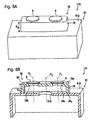
- a support body 61 of a vent member 63 shown in Fig. 6A and 6B includes a base portion 611 to be connected to the housing 91.
- An area of the base portion 611 defined by an outline of a lateral cross-section perpendicular to the thickness direction of the gas permeable membrane 6 increases continuously or stepwise from the side on which the gas permeable membrane 6 is disposed toward the side that is to be connected to the housing 91.
- the base portion 611 of the support body 61 is fixed to the opening portion 91k of the housing 91.
- the upper portion (opposite side to the housing) adjacent to the base portion 611 is a fixed-diameter portion 610 having a fixed outer diameter.
- a cover 61a covering the gas permeable membrane 6 is included in the fixed-diameter portion 610.
- a clearance between the gas permeable membrane 6 and the cover 61a communicates with an opening 62 that opens in a direction parallel to the in-plane of the gas permeable membrane 6.
- a vent structure 110 is constituted by attaching the vent member 63 to the opening portion 91k of the housing 91.
- the base portion 611 of the support body 61 prevents the water droplets or the like adhering to the outer surface 91p of the housing 91 from accumulating around the vent member 63.
- Fig. 6C is a view explaining operation of a vent member of this embodiment and Fig. 6D is that of a conventional vent member.
- a water droplet W has to increase its surface area in order to accumulate between the vent member 63 and the outer surface 91p of the housing 91, and thus becomes unstable. Thereby the water droplet W smoothly is removed from the area around the vent member 63.
- a conventional vent member 201 has a side surface rising perpendicularly.
- the above-mentioned cross-sectional outline of the base portion is approximately circular, and a diameter of the base portion increases continuously.
- Through hole 61h and 61i is formed so as to extend in the height direction from an end face 61q on the larger-diameter side to an opening end face 61p on the smaller-diameter side of the base portion 611.
- the gas permeable membrane 6 is disposed in the through hole 61h and 61i.
- the base portion 611 having the circular cross-section even more effectively prevents water droplets or the like from accumulating around the vent member 63.
- a height H 10 from the end face 61q (a second opening end face 61q aligned with the outer surface 91p of the housing 91) on the large-diameter side to the opening end face 61p (a first opening end face 61p) on the small-diameter side is set to 4 mm or more. More preferably, a height H 11 from the end face 61q on the larger-diameter side of the base portion 611 to the gas permeable membrane 6 is set to 4 mm or more as in the embodiments above.
- the base portion 611 has an outer diameter increasing continuously toward the side of the housing 91.
- the vent member can be of a very simple structure by removing the cover 61a and disposing the gas permeable membrane 6 on the opening end face 61p.
- the reinforced gas permeable membrane 8 (see Fig. 5C ) can be suitably adopted instead of the gas permeable membrane 6.
- a vent member 73 shown in Figs. 7A and 7B is provided with a box-shaped support body 71 and the gas permeable membrane 6 fixed to the support body 71 so as to close an opening portion 71k of the box-shaped support body 71.
- the box-shaped support body 71 has an interior space SH to serve as a gas passage between the interior and the exterior of the housing 91 and the opening portion 71k through which the interior space SH communicates with the exterior of the support body 71.
- a thickness direction of the gas permeable membrane 6 is a height direction
- one end face 71q of the support body 71 in the height direction serves as a bonding surface 71q directly bonded to the housing 91.
- the vent member 73 is fixed directly to the housing 91 so that the opening portion 91k of the housing 91 is exposed to the interior space SH of the support body 71.
- a height H 12 from the bonding surface 71q to an end face 71p in which the opening portion 71k is formed is set to 4 mm or more.
- the opening portion 91k of the housing 91 and the gas permeable membrane 6 are arranged in a staggered positional relationship in an in-plane direction (lateral direction) perpendicular to the height direction.
- a central axis O 1 of the circular gas permeable membrane 6 and a central axis O 2 of the opening portion 91k (also circular) of the housing 91 are not aligned.
- the opening portion 71k of the support body 71 and the opening portion 91k of the housing 91 are arranged so as to avoid overlapping each other in the in-plane. According to such a positional relationship, the interior space SH of the vent member 73 increases in the in-plane direction, making even more difficult for the water droplets or the like to reach the gas permeable membrane 6.
- a vent member 78 that includes a support body 76 having plural openings 76k, 76k and plural gas permeable membranes 6, 6 fixed to the support body 76 so as to close each of these openings 76k, 76k.
- a vent structure 115 is constituted by fixing the vent member 78 to the housing 91 in such an arrangement that the opening portion 91k of the housing 91 is located almost in the middle between the opening portions 76k, 76k that are adjacent to each other on the support body 76.
- the central axes O 1 and 0 3 of the gas permeable membranes 6, 6 are not aligned with the central axis O 2 of the opening portion 91k of the housing 91. According to the vent structure 115, the ventilation level inside the housing 91 is extremely high.
- An end face 76q which is on the opposite side of an end face 76p on which the gas permeable membranes 6 and 6 are disposed, serves as a bonding surface that is in contact with the outer surface 91p of the housing 91.
- the height H 12 from the outer surface 91p of the housing 91 to the end face 76p in which opening portions 76k, 76k are formed is 4 mm or more as in the embodiments described so far. This prevents the water droplets or the like adhering to the outer surface 91p of the housing 91 from flowing onto the gas permeable membranes 6, 6.
- the gas permeable membranes 6, 6 closing the opening portions 76k, 76k may be disposed from the side of the interior space SH of the box-shaped support body 76 like a vent member 78A and a vent structure 115A shown in Figs. 8C and 8D .
- a vent structure 115B shown in Fig. 8E a vent member 78B with a cover 76a covering the gas permeable membranes 6, 6 is adopted.
- the vent member 78B is provided with the cover 76a forming a clearance between itself and the gas permeable membranes 6, 6 while covering the gas permeable membranes 6, 6 on the side opposite to the side that is attached to the housing 91.
- the cover 76a can protect the gas permeable membranes 6, 6 from a strong water stream and dust in a reliable manner. Since the cover 76a opens in a direction parallel to the in-plane of the gas permeable membrane 6, there is no fear that the gas permeability of the gas permeable membrane 6 will be decreased.
- a vent structure 117 shown in Figs. 9A and 9B adopts a vent member 83 including upper faces of different heights.
- a support body 81 of the vent member 83 is formed of a tubular portion 81a on which the gas permeable membrane 6 is disposed and a box-shaped portion 81b having the interior space SH that communicates with the tubular portion 81a.
- the tubular portion 81a has a through hole 81h to serve as a gas passage.
- the gas permeable membrane 6 is disposed on an opening end face 81p of the tubular portion 81a, and closes the through hole 81h from the side opposite to the side adjacent to the box-shaped portion 81b.
- a height H 13 from the outer surface 91p of the housing 91 to the gas permeable membrane is 4 mm or more as in the embodiments above. Furthermore, the tubular portion 81a and the box-shaped portion 81b jointly form a stepped shape. This configuration makes it difficult for the water drops or the like adhering to the outer surface 91p of the housing 91 to flow toward the gas permeable membrane 6.
- the vent member 83 having different heights at different points like this embodiment may be adopted.
- the tubular portion 81a with the gas permeable membrane 6 is located in an area where a sufficient space can be taken while the box-shaped portion 81b with a reduced height is located in an area where there is no sufficient space.
- a support body 151 of the vent member 153 is provided with a through hole 151h to serve as a gas passage having a noncircular (rectangular in this embodiment) cross section.
- the support body 151 includes a stepped portion 512 on which a gas permeable membrane 8 is disposed and a cover 151a that prevents the through hole 151h from directly being exposed upward.
- the through hole 151h communicates with an opening 152 that opens in a lateral direction.
- the stepped portion 512 of the support body 151 is provided with a countersink 512g for fitting the gas permeable membrane 8 (specifically the portion of the reinforcement member 7), and thereby the gas permeable membrane 8 easily can be located with respect to the support body 151.
- material waste can be minimized by adopting the rectangular gas permeable membrane 8.
- the support body 151 of the vent member 153 includes a rib 154 for ultrasonic welding. Friction generated by a ultrasonic wave is concentrated on the rib 154 and melt it quickly for bonding the vent member 153 to the housing. Thereby the time needed for the bonding process can be shortened.
- the rib 154 may be provided to the support bodies of other embodiments.
- a problem such as separation and breakage of the gas permeable membrane during the insert molding also can be prevented by a vent member 163 included in a vent structure 160 shown in Fig. 11 .
- the vent member 163 is provided with the gas permeable membrane 6, a circular cylindrical support body 161 on one of whose opening end faces the gas permeable membrane 6 is disposed, and a reinforcement member 9 with a peripheral portion 9s fixed to the support body 161 so as to sandwich the gas permeable membrane 6 between the support body 161 and itself.
- the peripheral portion 9s of the reinforcement member 9 extends outward beyond the opening end face of the support body 161 on the side on which the gas permeable membrane 6 is disposed.
- the peripheral portion 9s turns around to a side surface of the support body 161 and is fixed to the support body 161.
- the peripheral portion 9s turns around to a side surface of the support body 161 and is fixed to the support body 161.
- the reinforcement member 9 preferably includes a porous body or a mesh, and more preferably, the reinforcement member 9 consists of a mesh made of metal or resin. Furthermore, it is preferable that the reinforcement member 9 has flexibility so that the peripheral portion 9s can fit along the side surface of the support body 161 with ease, and accordingly the reinforcement member 9 can be fixed to the support body 161 in a reliable manner.
- a mesh made of resin is suitable as the reinforcement member 9 because it has excellent flexibility and strength.
- the reinforcement member 9 may or may not be bonded directly to the gas permeable membrane 6. In other words, the reinforcement member 9 simply may be placed on the gas permeable membrane 6.
- the method of fixing the peripheral portion 9s of the reinforcement member 9 to the support body 161 is not particularly limited. A method such as welding, the use of an adhesive agent, an adhesive tape or the like can be adopted.
- a vent member of the present invention is suitable for housings of autoparts, such as lamps, motors, sensors, switches, ECUs, and gearboxes. Especially, the vent member of the present invention exhibits remarkable effect when it is attached to a housing that easily causes moisture condensation inside, directly is exposed to a rainstorm, or receives water streams during car washing.
- the vent member of the present invention also can be suitably attached to housings of electric appliances, such as mobile communication devices, cameras, electric shavers, and electric toothbrushes, besides autoparts.
Abstract
A vent structure 109A of the present invention includes a housing 91 and a vent member 13A attached to an opening portion 91k of the housing 91. The vent member 13A is provided with a support body 11 having a through hole 11h to serve as a gas passage between the interior and the exterior of the housing 91 and a gas permeable membrane 6 fixed to the support body 11 so as to close the through hole 11h. Assuming that a thickness direction of the gas permeable membrane is a height direction, a height H1 of the support body 11 from a second opening end face 11q (aligned with an outer surface 91p of the housing 91) to a first opening end face 11p on the other side is set to 4 mm or more.
Description
- The present invention relates to a vent member attached to a housing that accommodates automobile components, electronic components or the like. The present invention also relates to a vent structure using the vent member.
- Housings that accommodate automobile electrical components such as lamps, sensors and ECUs (electronic control unit) have a vent member attached thereto to ensure ventilation between the interior and the exterior of the housing and to prevent foreign matter from intruding into the housing. One example of such a vent member is disclosed in
JP 2004-47425A JP 2003-336874A - A vent member disclosed in
JP2004-47425A support body 203 on which a gaspermeable membrane 202 is disposed and acover part 204 attached to thesupport body 203 so as to cover the gaspermeable membrane 202, as shown inFig. 13 . Thevent member 201 thus configured is fixed to anopening portion 207 of ahousing 206 via an O-ring 205. Gas is allowed to permeate through the gaspermeable membrane 202 so that ventilation between the interior and the exterior of thehousing 206 is ensured. Thecover part 204 prevents the gaspermeable membrane 202 from being damaged by an external force, and deteriorated in gas permeability due to the deposition of dust. - The vent member shown in
Fig. 13 can be attached to the opening portion of the housing with ease. Furthermore, the protrusion from an outer surface of the housing is relatively low. This seems to be preferable because the vent member occupies no excess space. However, intensive studies made by the inventor have found that this is not always the case. - To be more specific, it is assumed that the gas permeable membrane of the vent member is close to the outer surface of the housing when the vent member is attached to the opening portion of the housing. When water droplets or oil droplets adhere to the outer surface of the housing in such a case, the water droplets or the like possibly flow toward a surface of the gas permeable membrane easily along a side surface the support body to which the gas permeable membrane is fixed. This phenomenon becomes obvious when the water droplets or oil droplets remain around a boundary between the vent member and the housing and the atmospheric pressure inside the housing rapidly drops below the atmospheric pressure outside the housing.
- In view of the foregoing, the present invention has an object to provide a vent member that can prevent water droplets or the like from flowing toward the gas permeable membrane even when the droplets adhere to the outer surface of the housing, and thereby can maintain gas permeability in a reliable manner. The present invention has another object to provide a vent structure using this vent member.
- More specifically, the present invention provides a vent member to be attached to a housing that needs ventilation. The vent member includes a support body having a through hole to serve as a gas passage between the interior and the exterior of the housing and a gas permeable membrane fixed to the support body so as to close the through hole. Assuming that a thickness direction of the gas permeable membrane is a height direction, the support body is formed so that the through hole extends in the height direction from one opening end face to the other opening end face, and the height from the one opening end face to the other opening end face is set to 4 mm or more.
- Another aspect of the present invention also provides a vent member to be attached to a housing that needs ventilation. The vent member includes a support body having a through hole to serve as a gas passage between the interior and the exterior of the housing, and a gas permeable membrane fixed to the support body so as to close the through hole. The support body includes a base portion to be connected to the housing. An area of the base portion defined by an outline of a lateral cross-section perpendicular to the thickness direction of the gas permeable membrane increases continuously or stepwise from the side on which the gas permeable membrane is disposed toward the side that is to be connected to the housing.
- Still another aspect of the present invention provides a vent member to be attached to a housing that needs ventilation. The vent member includes a support body having an interior space to serve as a gas passage between the interior and the exterior of the housing and an opening portion through which the interior space communicates with the exterior of the housing, and a gas permeable membrane fixed to the support body so as to close the opening portion. Assuming that a thickness direction of the gas permeable membrane is a height direction, one of the end faces of the support body in the height direction serves as a predetermined fixing surface that is to be fixed to the housing directly or via another member, and the height from the predetermined fixing surface to the end face on the other side on which the opening portion is formed is set to 4 mm or more.
- Still another aspect of the present invention provides a vent structure including a housing that needs ventilation and the above-mentioned vent member attached to an opening portion of the housing.
- In the vent member (or the vent structure) of the present invention described above, the height from the outer surface of the housing to the opening end face on the opposite side sufficiently is ensured as 4 mm or more. This makes it possible to prevent water droplets or the like from flowing onto the gas permeable membrane even when water droplets or the like remain in areas including a connection point between the vent member and the housing. In other words, it is possible to obtain a vent member that can maintain gas permeability in a reliable manner even when water droplets or the like adhere to the outer surface of the housing.
- In the vent member (or the vent structure) of another aspect of the present invention, the support body, to which the gas permeable membrane is fixed, includes the base portion having a lateral cross-sectional area increasing continuously or stepwise toward the housing. According to such a structure, it becomes difficult for water droplets or the like to remain around the border between the vent member and the housing. As a result, it is possible to obtain a vent member that can prevent water droplets or the like from flowing onto the gas permeable membrane even when the water droplets or the like adhere to the outer surface of the housing, and thereby can maintain gas permeability in a reliable manner.
-
-
Fig. 1A is a perspective view of a vent member of a first embodiment according to the present invention. -
Fig. 1B is a sectional perspective view of the vent member ofFig. 1A . -
Fig. 2A is a sectional perspective view of a modification of the vent member ofFig. 1A . -
Fig. 2B is a sectional perspective view of another modification of the vent member shown ofFig. 1A . -
Fig. 3A is a perspective view of a vent member of a second embodiment. -
Fig. 3B is a sectional perspective view of the vent member ofFig. 3A . -
Fig. 4A is a sectional perspective view of a vent member of a third embodiment. -
Fig. 4B is a sectional perspective view of a modification of the vent member ofFig. 4A . -
Fig. 5A is a perspective view of a vent member of a fourth embodiment. -
Fig. 5B is a sectional perspective view of the vent member ofFig. 5A . -
Fig. 5C is a sectional perspective view of the modification of the vent member ofFig. 5A . -
Fig. 5D is a sectional perspective view of another modification of the vent member shown inFig. 5A . -
Fig. 6A is a perspective view of a vent member of a fifth embodiment. -
Fig. 6B is a sectional perspective view of the vent member ofFig. 6A . -
Fig. 6C is a view explaining operation of the vent member ofFig. 6A . -
Fig. 6D is a view explaining operation of a conventional vent member. -
Fig. 7A is a perspective view of a vent member of a sixth embodiment. -
Fig. 7B is a sectional perspective view of the vent member ofFig. 7A . -
Fig. 8A is a perspective view of a modification of the vent member shown inFig. 7A . -
Fig. 8B is a sectional perspective view of the vent member ofFig. 8A . -
Fig. 8C is a perspective view of another modification of the vent member shown inFig. 7A . -
Fig. 8D is a sectional perspective view of the vent member ofFig. 8C . -
Fig. 8E is a sectional perspective view of a further modification of the vent member shown inFig. 7A . -
Fig. 9A is a perspective view of a vent member of a seventh embodiment. -
Fig. 9B is a sectional perspective view of the vent member ofFig. 9A . -
Fig. 10A is a perspective view of a vent member of an eighth embodiment. -
Fig. 10B is a sectional perspective view of the vent member ofFig. 10A . -
Fig. 11 is a perspective view of a vent member of a ninth embodiment. -
Fig. 12 is a general view of a housing on which a vent member is attached. -
Fig. 13 is a side view of a conventional vent member. - Hereinafter, embodiments of the present invention will be described with reference to the attached drawings.
Fig. 1A is a perspective view of a vent member of a first embodiment according to the present invention, andFig. 1B is a sectional perspective view thereof.Fig. 12 is a general view of a housing on which the vent member ofFig. 1A is attached. As shown inFig. 12 , thevent member 13A shown inFig. 1A and 1B constitutes avent structure 100A for providing ventilation between the interior and the exterior of ahousing 91 when attached to anopening portion 91k of thehousing 91 of, for example, an automobile electrical component. The housing is not limited to a box-shaped housing as shown inFig. 12 . Any components or articles having an interior space that needs ventilation can be a housing to which the vent member of the present invention is to be attached. - As shown in
Fig. 1A and 1B , thevent member 13A is provided with asupport body 11 having a throughhole 11h to serve as a gas passage between the interior and the exterior of thehousing 91 and a gaspermeable membrane 6 disposed on thesupport body 11 so as to close one of the openings of the throughhole 11h. Thesupport body 11 is of an approximately circular cylindrical shape. The gaspermeable membrane 6 of a circular shape is disposed on a firstopening end face 11p, which is one of the opening end faces of the circularcylindrical support body 11. A diameter of the gaspermeable membrane 6 is smaller than an outer diameter of thesupport body 11 and larger than an inner diameter of thesupport body 11 at the first openingend face 11p. The vent member 13Ais fixed to theopening portion 91k of thehousing 91 in such a manner that the throughhole 11h of thesupport body 11, the gaspermeable membrane 6 and theopening portion 91k of thehousing 91 are arranged concentrically. That is, one of the openings of the throughhole 11 formed in thesupport body 11 is closed by the gaspermeable membrane 6 while the other opening opens toward the interior of thehousing 91. The gaspermeable membrane 6 allows a gas to permeate therethrough and prevents entry of foreign matter, such as water droplets and dust. The gas permeability of the gaspermeable membrane 6 maintains the pressure inside of thehousing 91 equal to the pressure outside of the housing. - The
support body 11 of thevent member 13A includes acover 16 forming a clearance between the gaspermeable membrane 6 and itself and covering the gaspermeable membrane 6 on the side opposite to the side that is to be attached to theopening portion 91k of thehousing 91. In short, of the first openingend face 11p and a secondopening end face 11q, which are the two opening end faces of thesupport body 11, the first openingend face 11p located on the opposite side of the secondopening end face 11q is covered with thecover 16. The clearance is formed between the first openingend face 11p and thecover 16, and it communicates with anopening 16h that opens in a direction parallel to an in-plane of the gaspermeable membrane 6. Such a structure protects the gaspermeable membrane 6 from water droplets and dust and ensures ventilation between the interior and the exterior of thehousing 91 through the gaspermeable membrane 6. It should be noted that in this embodiment, thecover 16 is manufactured as a separate part from thesupport body 11 having the throughhole 11h. Thecover 16 is combined with thesupport body 11 after the gaspermeable membrane 6 is fixed on the first openingend face 11p. - The
support body 11 as described above can be manufactured by popular molding techniques, such as injection molding, compression molding, and cutting. From the viewpoint of moldability, a thermoplastic resin is preferably used as a material for thesupport body 11. Specifically, thermoplastic resins such as PBT (polybutylene terephthalate), PA (nylon) and PET (polyethlene terephthalate), and thermoplastic elastomers such as EPDM (ethylene propylene rubber) and silicone rubber can be used. The materials for thesupport body 11 may include pigments such as carbon black and titanium white, reinforcement fillers such as glass particles and glass fibers, and water repellants. Thesupport body 11 repels liquid (such as water and oil) more easily when applied with a liquid-repellent treatment on its surface. Other treatments for providing desired characteristics such as adhesiveness improvement, electrical insulation, semiconductivity, conductivity may be applied on thesupport body 11. - On the other hand, the gas
permeable membrane 6 is not particularly limited in terms of structure and material as long as it is a membrane that allows gas permeation while preventing liquid permeation. This embodiment describes the gaspermeable membrane 6 formed by laminating a reinforcing layer on a resin porous membrane. More specifically, this embodiment describes the gaspermeable membrane 6 with three layers (for example, TEMISH (registered trademark) available from Nitto Denko Corp.) formed by laminating a resin porous membrane on top and bottom of a reinforcing layer. With the reinforcing layer, the gaspermeable membrane 6 is allowed to have a higher strength. - As a material for the resin porous membrane, a fluororesin porous body and a polyolefin porous body that can be manufactured by a known drawing method or extracting method can be used. Examples of the fluororesin include PTFE (polytetrafluoroethylene), polychlorotrifluoroethylene, tetrafluoroethylene-hexafluoropropylene copolymer, and tetrafluoroethylene-ethylene copolymer. Examples of the monomer of which the polyolefin is composed include ethylene, propylene and 4-methylpentene-1,1 butene. It is possible to use a polyolefin obtained by polymerizing these monomers independently or copolymerizing them. A nanofiber film porous body or the like using polyacrylonitrile, nylon and polylactate also can be used. In particular, a PTFE porous body is preferably used because it can ensure gas permeability even with a small area and prevent foreign matter from intruding into the housing in a highly effective manner.
- The liquid-repellent treatment may be applied to the resin porous membrane that forms the gas
permeable membrane 6 in accordance with the application of the housing. The liquid-repellent treatment can be carried out by applying the resin porous membrane with a substance having small surface tension, drying the substance and then curing the substance. A liquid-repellent agent used for the liquid-repellent treatment is not particularly limited as long as it can form a coating having a surface tension lower than that of the resin porous membrane. For example, a liquid-repellent agent containing polymers having perfluoroalkyl groups is suitable. The liquid-repellent agent may be applied by impregnation, spraying or the like. From the viewpoint of ensuring sufficient waterproofness, the average pore diameter of the resin porous membrane is preferably 0.01 µm or more and not more than 10 µm. - It is preferable that the material of the reinforcing layer forming the gas
permeable membrane 6 excels more in gas permeability than the resin porous membrane. Specifically, a fabric, a nonwoven fabric, a mesh, a net, a sponge, a form, a porous body (Sunmap available from Nitto Denko Corp., for example) or the like can be used. These are made of resin or metal. Examples of the methods for bonding the resin porous membrane to the reinforcing layer include adhesive lamination, heat lamination, heat welding, laser welding, ultrasonic welding, and the use of an adhesive agent. - The thickness of the gas
permeable membrane 6 is set in the range of, for example, 1 µm to 5 mm, taking into account its strength and the ease of fixing to thesupport body 11. The gas permeability of the gaspermeable membrane 6 is preferably in a rage of 0.1 to 300 sec/100 cm3 in terms of Gurley value. Although the gaspermeable membrane 6 is fixed to thesupport body 11 by heat welding in this embodiment, the gaspermeable membrane 6 may be fixed to thesupport body 11 by other methods such as ultrasonic welding and the use of an adhesive agent. - Descriptions made herein regarding the support body and the gas permeable membrane apply to other embodiments to be described later.
- A thickness direction of the gas
permeable membrane 6 is assumed as a height direction in the descriptions hereinafter including other embodiments. It is also assumed that the surface of the gaspermeable membrane 6 facing to the side of thehousing 91 is an under surface while the surface on the opposite side is an upper surface. - As shown in
Fig. 1A and 1B , anouter surface 91p of thehousing 91 surrounding thevent member 13A is a flat surface approximately parallel to a principal surface of the gaspermeable membrane 6 in this embodiment, As shown inFig. 1B , the secondopening end face 11q on the opposite side of the first openingend face 11p to which thegas 6 is fixed is a bonding surface that is directly bonded to theopening portion 91k of thehousing 91. The throughhole 11h is formed so as to extend almost linearly in the height direction from the secondopening end face 11q to the first openingend face 11p. - In the
support body 11, a height H1 from the secondopening end face 11q to the gaspermeable membrane 6, in other words, a height H1 from theouter surface 91p of thehousing 91 surrounding thevent member 13A to the gaspermeable membrane 6, is set to 4 mm or more. When thus configured, it is possible to prevent the water droplets or the like adhering to theouter surface 91p of thehousing 91 from flowing onto the gaspermeable membrane 6 in a highly effective manner. The height H1 of 4 mm or more makes it difficult for the water droplets or the like adhering to thehousing 91 to reach the gaspermeable membrane 6 under normal conditions. The height H1 is set preferably to 6 mm or more, further preferably to 10 mm or more, in order to prevent the water droplets or the like from contacting the gaspermeable membrane 6 in a more reliable manner. It is desirable, however, that the height H1 is 30 mm or less in order to avoid an excessive protrusion of thevent member 13A from theouter surface 91p of thehousing 91. These dimensions apply to other embodiments to be described later. - A method such as heat welding, ultrasonic welding, laser welding, the use of an adhesive tape, the use of an adhesive agent can be adopted for fixing the
vent member 13A to theopening portion 91k of thehousing 91. In thevent member 13A shown inFig. 1A and 1B , the height H1 of thesupport body 11 from theouter surface 91p of thehousing 91 to the under surface of the gaspermeable membrane 6 is set to be smaller than the outer diameter of thesupport body 11 in a cross section perpendicular to the height direction. This makes it possible to obtain a sufficient stability when thevent member 13A is fixed to theopening portion 91k of thehousing 91, and thereby reduce the possibility that thevent member 13A falls off thehousing 91 when an impact is applied thereto by foreign matter or the like. -
Ribs opening end face 11q, like a vent member 13B shown inFig. 2A . Theribs outer surface 91p of thehousing 91. According to a vent structure 100B in which the vent member 13B is attached to theopening portion 91k of thehousing 91, the bonding strength between the vent member 13B and thehousing 91 can be increased with ease. Theribs - Incidentally, the vent member of the present invention is, in some cases, available for so-called insert molding. In the insert molding, the vent member is inserted to a mold for molding the housing so as to be integrated with the resin of which the housing will be composed. According to such an insert molding method, good productivity is achieved because it can omit the step of attaching the vent member to the housing. However, there may be a possibility that a rate of occurrence of defective products rises in exchange for the reduced number of production steps. This is because when the insert molding is being carried out, a high atmospheric pressure is applied to the gas permeable membrane of the vent member, causing the gas permeable membrane to fall off the support body or to be broken in some cases. In order to deal with this problem, the improvement below is effective.
- That is, like a
vent member 13C included in a vent structure 100C shown inFig. 2B , a gaspermeable membrane 8 can be used that includes amain membrane body 6 formed of the resin porous membrane and a gas-permeable reinforcement member 7 attached to themain membrane body 6 so as to cover at least one of the principal surfaces of themain membrane body 6. Themain membrane body 6 is reinforced by the reinforcement member 7. When configured in this manner, it is possible to prevent or suppress occurrence of failures, such as separation and breakage of themain membrane body 6 during thehousing 91 is being molded. Themain membrane body 6 is exactly the gas permeable membrane shown inFig. 1A and 1B , as can be understood from the fact that the same reference numeral is given to each of them. - The reinforcement member 7 is required to have characteristics that can ensure the gas permeability of the
main membrane body 6 and excel more at preventing separation and breakage than themain membrane body 6. Hence, it is preferable that the reinforcement member 7 includes a mesh made of metal or resin. It is more preferable that the reinforcement member 7 is formed of a mesh. It is preferable that themain membrane body 6 and the reinforcement member 7 are bonded by heat welding or the use of an adhesive agent to be integrated together. It is also preferable that the reinforcement member 7 is composed of a resin having substantially the same composition as that of the resin of which the support body is composed. This allows thesupport body 11 and the reinforcement member 7 to be bonded together more tightly by a welding method, such as heat welding, ultrasonic welding and laser welding. The metal or resin mesh may be formed of woven metal wires or woven resin wires, a sheet perforated with many holes like a known punching metal, and a molded body manufactured by a known molding method using a mold, and further, a grid-like material having a high rigidity. In the example ofFig. 2B , the reinforcement member 7 is bonded only to one side of themain membrane body 6, but it may be disposed on both sides of themain membrane body 6. The term "substantially the same composition" referred to herein is not intended to exclude the case where an inevitable impurity is contained, and the case where a slight difference exists that has no significant effect on the characteristics. - In the vent member described in this and other embodiments, the support body may be dividable into an upper portion and a lower portion in the area other than the cover. Furthermore, a vent member provided with a support body having no cover and the gas permeable membrane exposed upward may be adopted.
-
Fig. 3A is a perspective view of a vent member of a second embodiment, andFig. 3B is a sectional perspective view thereof. Avent structure 102 for performing ventilation between the interior and the exterior of thehousing 91 is constituted by attaching avent member 23 shown inFig. 3A and 3B to theopening portion 91k of thehousing 91. - The
vent member 23 is provided with asupport body 21 having a throughhole housing 91 and the gaspermeable membrane 6 fixed to thesupport body 21 so as to close the throughhole opening end face 21q serves as a bonding surface that is directly bonded to thehousing 91. Thesupport body 21 includes acover 26 covering the gaspermeable membrane 6. A clearance between the gaspermeable membrane 6 and thecover 26 communicates with anopening 26h that opens in a direction parallel to the in-plane of the gaspermeable membrane 6. Thevent member 23 shares these points with the vent member 13 of the first embodiment. - On the other hand, a first
opening end face 21p located on the farther side from thehousing 91 serves as an end face to which thecover 26 is fixed. The gaspermeable membrane 6 is not disposed on the first openingend face 21p. In this embodiment, the gaspermeable membrane 6 is disposed in the throughhole hole first portion 21h that is outside of thehousing 91 and asecond portion 21i that is inside of thehousing 91, and divided by the gaspermeable membrane 6. When the gaspermeable membrane 6 is disposed in the throughhole support body 21 from the secondopening end face 21q (an end face aligned with theouter surface 91p of the housing 91) to the first openingend face 21p on the opposite side may be set to 4 mm or more. When configured in this manner, it is possible to prevent highly effectively the water droplets or the like adhering to theouter surface 91p of thehousing 91 from flowing over thesupport body 21 and intruding into the throughhole 21h. - More preferably, a height H2 of the
support body 21 from the secondopening end face 21q to the under surface of the gaspermeable membrane 6 is 4 mm or more. When configured in this manner, it is possible to obtain a sufficient length for the throughhole 21i which is inside of thehousing 91. The throughhole 21i with an adequate length is advantageous in that it can prevent water droplets from immediately adhering to the gaspermeable membrane 6 even when moisture condensation occurs in thehousing 91 because the water droplets slowly flows inside of the throughhole 21i. This is also preferable because the height H3 from theouter surface 91p of thehousing 91 to the first openingend face 21p naturally becomes 4 mm or more when the height H2 from theouter surface 91p of thehousing 91 to the gaspermeable membrane 6 is set to 4 mm or more. - The
support body 21 includes a steppedportion 211 formed along an entire circumference inside the throughhole hole portion 211 includes the boundary between thefirst portion 21h and thesecond portion 21i of the throughhole permeable membrane 6 is disposed on this steppedportion 211. According to this structure, the gaspermeable membrane 6 can be disposed in the throughhole permeable membrane 6 in the throughhole permeable membrane 6 from water droplets and dust that come flying from the lateral direction. In this embodiment, the diameter of the throughhole 21h, which is outside of thehousing 91, is set to be larger than the diameter of the gaspermeable membrane 6. The gaspermeable membrane 6 is inserted from the throughhole 21h to be fixed to the steppedportion 211. When configured in this manner, the gaspermeable membrane 6 can be fixed to the steppedportion 211 with ease. - A reinforced gas permeable membrane 8 (see
Fig. 2B ) may be used instead of the gaspermeable membrane 6. In this case, the gaspermeable membrane 8 is fixed to thesupport body 21 so that the reinforcement member 7 or themain membrane body 6 is in contact with a seating face of the steppedportion 211. - A
vent member 43A of a third embodiment shown inFig. 4A is a modification of thevent member 23 of the second embodiment. Avent structure 106A is constituted by attaching thevent member 43A to theopening portion 91k of thehousing 91. This embodiment is common with the embodiments above in that a throughhole permeable membrane 6, asupport body 41 includes acover 46, and a height H7 from theouter surface 91p of thehousing 91 to a firstopening end face 41p is set to 4 mm or more. A difference is that the gaspermeable membrane 6 is integrated with thesupport body 41 by insert molding. - As shown in
Fig. 4A , the gaspermeable membrane 6 is fixed to thesupport body 41 in the throughhole peripheral portion 6k with the resin of which thesupport body 41 is composed. In other words, theperipheral portion 6k of the gaspermeable membrane 6 is embedded into thesupport body 41. When configured in this manner, the gaspermeable membrane 6 can be fixed to thesupport body 41 more tightly. Should thevent member 43A be exposed to a strong water stream, the gaspermeable membrane 6 will not fall off thesupport body 41. It is preferable also in this embodiment that thesupport body 41 of thevent member 43A has a height H6 of 4 mm or more from theouter surface 91p (aligned with a secondopening end face 41q) of thehousing 91 to the gaspermeable membrane 6. - In the
vent member 43A of this embodiment, the outer diameter of anopening portion 41L on the side that is bonded to thehousing 91 is larger than the outer diameter of the opening portion on the opposite side. According to thesupport body 41 with theopening portion 41L, the area of thebonding surface 41q is increased, and thereby the bonding strength between thevent member 43A and thehousing 91 is enhanced. It goes without saying that theopening portion 41L can be adopted to an vent member of other embodiments. - Like a
vent member 43B included in avent structure 106B shown inFig. 4B , it is also possible to use the gaspermeable membrane 8 including themain membrane body 6 and the reinforcement member 7. In this case, the peripheral portion of themain membrane body 6 and that of the reinforcement member 7 are both embedded into thesupport body 41. The gaspermeable membrane 8 can be fixed to thesupport body 41 more tightly with the combination of the reinforcing effect of the reinforcement member 7 and the effect of being embedded into thesupport body 41. -
Fig. 5A is a perspective view of a vent member of a fourth embodiment, andFig. 5B is a sectional perspective view thereof. Avent member 53A shown inFig. 5A and Fig. 5B is a modification of the second embodiment. The gaspermeable membrane 6 is disposed in a throughhole support body 51, thesupport body 51 includes acover 51a, and a height H8 from theouter surface 91p of thehousing 91 to a firstopening end face 51p is set to 4 mm or more. These points are common with thevent member 23 and thevent structure 102 shown inFig. 3A and 3B . It is also common in that a secondopening end face 51q of thesupport body 51 serves as a bonding surface to thehousing 91, and avent structure 108A is constituted by attaching thevent member 53A to theopening portion 91k of thehousing 91. - As shown in
Fig. 5B , thesupport body 51 includes a steppedportion 511 formed along an entire circumference inside the throughhole hole portion 511. In other words, the steppedportion 511 includes the boundary between afirst portion 51h and asecond portion 51i of the throughhole permeable membrane 6 is disposed on this steppedportion 511. It should be noted that in thevent member 53A, of the throughhole support body 51, the throughhole 51h exposed to outside of thehousing 91 has a smaller diameter than the throughhole 51i that is inside of thehousing 91. The gaspermeable membrane 6 is inserted into the throughhole 51i from the side of the secondopening end face 51q connected to theopening portion 91k of thehousing 91, and then disposed on the steppedportion 511. - According to the
vent member 53A, a cross-sectional area of the throughhole portion 511 from the side attached to thehousing 91 toward the opposite side. Therefore, the gaspermeable membrane 6 is pressed onto a seating face of the steppedportion 511 when an air pressure is applied in a direction from thehousing 91 side to the opposite side. Hence, it is possible to reduce a rate of occurrence of separation and breakage of the gaspermeable membrane 6 during thehousing 91 with thevent member 53A is being manufactured by insert molding. - More preferably, the gas
permeable membrane 8 reinforced with the reinforcement member 7 is used like avent member 53B included in a vent structure 108B shown inFig. 5C . In this case, the gaspermeable membrane 8 is fixed to thesupport body 51 so that the reinforcement member 7 is in contact with the seating face of the steppedportion 511. According to thevent member 53B, themain membrane body 6 is pressed onto the reinforcement member 7 when an air pressure is applied in a direction from the side of thehousing 91 to the opposite side. The reinforcement member 7 preferably includes a mesh made of metal or resin, or a porous body (Sunmap available from NITTO DENKO Corp., for example) and has a rigidity higher than that of themain membrane body 6. The reinforcement member 7 thus configured has low possibilities of breakage and separation from thesupport body 51 due to an air pressure applied during the insert molding, and thereby firmly supports themain membrane body 6 at all times. As described above, it is preferable that the reinforcement member 7 is composed of a resin having substantially the same composition as that of the resin of which thesupport body 51 is composed. - It is preferable in this embodiment as well that the
support body 51 of thevent member outer surface 91p of thehousing 91 to the gaspermeable membrane 6. - Furthermore, in this embodiment, the
cover 51a of thesupport body 51 is integrally manufactured by injection molding with a body part in which the throughhole permeable membrane 6 and thecover 51a communicates with anopening 52 that opens in a direction parallel to the in-plane of the gaspermeable membrane 6. - A vent member 53D shown in
Fig. 5D also is suitable. Asupport body 51D of the vent member 53D includesbaffles permeable membrane 6 to thehousing 91 and prevent gas or liquid from traveling straight with respect to the height direction in the throughhole 51i. By disposing thesebaffles hole 51i, it is possible to prevent water droplets from flowing directly to the gaspermeable membrane 6 even when moisture condensation occurs in thehousing 91. When configured in this manner, it is possible to ensure the gas permeability of the gaspermeable membrane 6 at all times and eliminate the moisture condensation in thehousing 91 smoothly. Thesebaffles - A
support body 61 of avent member 63 shown inFig. 6A and 6B includes abase portion 611 to be connected to thehousing 91. An area of thebase portion 611 defined by an outline of a lateral cross-section perpendicular to the thickness direction of the gaspermeable membrane 6 increases continuously or stepwise from the side on which the gaspermeable membrane 6 is disposed toward the side that is to be connected to thehousing 91. Thebase portion 611 of thesupport body 61 is fixed to theopening portion 91k of thehousing 91. The upper portion (opposite side to the housing) adjacent to thebase portion 611 is a fixed-diameter portion 610 having a fixed outer diameter. Acover 61a covering the gaspermeable membrane 6 is included in the fixed-diameter portion 610. A clearance between the gaspermeable membrane 6 and thecover 61a communicates with anopening 62 that opens in a direction parallel to the in-plane of the gaspermeable membrane 6. Avent structure 110 is constituted by attaching thevent member 63 to theopening portion 91k of thehousing 91. Thebase portion 611 of thesupport body 61 prevents the water droplets or the like adhering to theouter surface 91p of thehousing 91 from accumulating around thevent member 63. -
Fig. 6C is a view explaining operation of a vent member of this embodiment andFig. 6D is that of a conventional vent member. First, as shown inFig. 6C , according to thevent member 63 of this embodiment having a sloping side surface so as to be wider toward thehousing 91, a water droplet W has to increase its surface area in order to accumulate between thevent member 63 and theouter surface 91p of thehousing 91, and thus becomes unstable. Thereby the water droplet W smoothly is removed from the area around thevent member 63. On the other hand, as shown inFig. 6D , aconventional vent member 201 has a side surface rising perpendicularly. This allows the water droplet W to have a smaller surface area and become stable when accumulating between thevent member 201 and theouter surface 91p of thehousing 91. As a result, the water droplet W tends to stay around thevent member 201 and flow onto the gaspermeable membrane 6 more easily. Especially, this becomes obvious with the conventional vent member 201 (Fig. 13 ) whose height to the gas permeable membrane is insufficient. - As shown in
Figs. 6A and 6B , in thevent member 63, the above-mentioned cross-sectional outline of the base portion is approximately circular, and a diameter of the base portion increases continuously. Throughhole end face 61q on the larger-diameter side to an openingend face 61p on the smaller-diameter side of thebase portion 611. The gaspermeable membrane 6 is disposed in the throughhole base portion 611 having the circular cross-section even more effectively prevents water droplets or the like from accumulating around thevent member 63. - Furthermore, it is preferable that a height H10 from the
end face 61q (a secondopening end face 61q aligned with theouter surface 91p of the housing 91) on the large-diameter side to the openingend face 61p (a firstopening end face 61p) on the small-diameter side is set to 4 mm or more. More preferably, a height H11 from theend face 61q on the larger-diameter side of thebase portion 611 to the gaspermeable membrane 6 is set to 4 mm or more as in the embodiments above. When configured in this manner, it is possible to prevent the water droplets or the like adhering to theouter surface 91p of thehousing 91 from flowing toward the gaspermeable membrane 6, and thereby thevent structure 110 with excellent waterproofness can be obtained. - In the embodiment of
Figs. 6A and 6B , thebase portion 611 has an outer diameter increasing continuously toward the side of thehousing 91. However, it is possible to provide a base portion whose outer diameter increases stepwise. The structure with a sloping side surface may be applied to other embodiments. For example, the vent member can be of a very simple structure by removing thecover 61a and disposing the gaspermeable membrane 6 on the openingend face 61p. The reinforced gas permeable membrane 8 (seeFig. 5C ) can be suitably adopted instead of the gaspermeable membrane 6. - A
vent member 73 shown inFigs. 7A and 7B is provided with a box-shapedsupport body 71 and the gaspermeable membrane 6 fixed to thesupport body 71 so as to close anopening portion 71k of the box-shapedsupport body 71. The box-shapedsupport body 71 has an interior space SH to serve as a gas passage between the interior and the exterior of thehousing 91 and theopening portion 71k through which the interior space SH communicates with the exterior of thesupport body 71. Assuming that a thickness direction of the gaspermeable membrane 6 is a height direction, one end face 71q of thesupport body 71 in the height direction serves as a bonding surface 71q directly bonded to thehousing 91. Thevent member 73 is fixed directly to thehousing 91 so that theopening portion 91k of thehousing 91 is exposed to the interior space SH of thesupport body 71. In thesupport body 71, a height H12 from the bonding surface 71q to anend face 71p in which theopening portion 71k is formed is set to 4 mm or more. When configured in this manner, it is possible to prevent the water droplets or the like adhering to theouter surface 91p of thehousing 91 from flowing onto the gaspermeable membrane 6. - In the
vent member 73 of this embodiment, theopening portion 91k of thehousing 91 and the gaspermeable membrane 6 are arranged in a staggered positional relationship in an in-plane direction (lateral direction) perpendicular to the height direction. To be more specific, a central axis O1 of the circular gaspermeable membrane 6 and a central axis O2 of theopening portion 91k (also circular) of thehousing 91 are not aligned. In a projection view in the height direction, theopening portion 71k of thesupport body 71 and theopening portion 91k of thehousing 91 are arranged so as to avoid overlapping each other in the in-plane. According to such a positional relationship, the interior space SH of thevent member 73 increases in the in-plane direction, making even more difficult for the water droplets or the like to reach the gaspermeable membrane 6. - As shown in
Figs. 8A and 8B , it is possible to adopt avent member 78 that includes asupport body 76 havingplural openings permeable membranes support body 76 so as to close each of theseopenings vent structure 115 is constituted by fixing thevent member 78 to thehousing 91 in such an arrangement that theopening portion 91k of thehousing 91 is located almost in the middle between the openingportions support body 76. The central axes O1 and 03 of the gaspermeable membranes opening portion 91k of thehousing 91. According to thevent structure 115, the ventilation level inside thehousing 91 is extremely high. - An
end face 76q, which is on the opposite side of anend face 76p on which the gaspermeable membranes outer surface 91p of thehousing 91. The height H12 from theouter surface 91p of thehousing 91 to theend face 76p in which openingportions outer surface 91p of thehousing 91 from flowing onto the gaspermeable membranes - The gas
permeable membranes portions support body 76 like avent member 78A and avent structure 115A shown inFigs. 8C and 8D . In a vent structure 115B shown inFig. 8E , avent member 78B with acover 76a covering the gaspermeable membranes vent member 78B is provided with thecover 76a forming a clearance between itself and the gaspermeable membranes permeable membranes housing 91. Thecover 76a can protect the gaspermeable membranes cover 76a opens in a direction parallel to the in-plane of the gaspermeable membrane 6, there is no fear that the gas permeability of the gaspermeable membrane 6 will be decreased. - A
vent structure 117 shown inFigs. 9A and9B adopts avent member 83 including upper faces of different heights. To be more specific, asupport body 81 of thevent member 83 is formed of atubular portion 81a on which the gaspermeable membrane 6 is disposed and a box-shapedportion 81b having the interior space SH that communicates with thetubular portion 81a. Thetubular portion 81a has a throughhole 81h to serve as a gas passage. The gaspermeable membrane 6 is disposed on an openingend face 81p of thetubular portion 81a, and closes the throughhole 81h from the side opposite to the side adjacent to the box-shapedportion 81b. A height H13 from theouter surface 91p of thehousing 91 to the gas permeable membrane is 4 mm or more as in the embodiments above. Furthermore, thetubular portion 81a and the box-shapedportion 81b jointly form a stepped shape. This configuration makes it difficult for the water drops or the like adhering to theouter surface 91p of thehousing 91 to flow toward the gaspermeable membrane 6. When the space allowed for placing thevent structure 117 is partially insufficient, thevent member 83 having different heights at different points like this embodiment may be adopted. In short, thetubular portion 81a with the gaspermeable membrane 6 is located in an area where a sufficient space can be taken while the box-shapedportion 81b with a reduced height is located in an area where there is no sufficient space. - Major features of a
vent member 153 shown inFig. 10A and10B are common with those of thevent member 53B shown inFig. 5C , although the shape is different. That is, asupport body 151 of thevent member 153 is provided with a throughhole 151h to serve as a gas passage having a noncircular (rectangular in this embodiment) cross section. Thesupport body 151 includes a steppedportion 512 on which a gaspermeable membrane 8 is disposed and acover 151a that prevents the throughhole 151h from directly being exposed upward. The throughhole 151h communicates with anopening 152 that opens in a lateral direction. The steppedportion 512 of thesupport body 151 is provided with acountersink 512g for fitting the gas permeable membrane 8 (specifically the portion of the reinforcement member 7), and thereby the gaspermeable membrane 8 easily can be located with respect to thesupport body 151. According to thevent member 153 of this embodiment, material waste can be minimized by adopting the rectangular gaspermeable membrane 8. - The
support body 151 of thevent member 153 includes arib 154 for ultrasonic welding. Friction generated by a ultrasonic wave is concentrated on therib 154 and melt it quickly for bonding thevent member 153 to the housing. Thereby the time needed for the bonding process can be shortened. Therib 154 may be provided to the support bodies of other embodiments. - A problem such as separation and breakage of the gas permeable membrane during the insert molding also can be prevented by a
vent member 163 included in a vent structure 160 shown inFig. 11 . Thevent member 163 is provided with the gaspermeable membrane 6, a circularcylindrical support body 161 on one of whose opening end faces the gaspermeable membrane 6 is disposed, and a reinforcement member 9 with a peripheral portion 9s fixed to thesupport body 161 so as to sandwich the gaspermeable membrane 6 between thesupport body 161 and itself. The peripheral portion 9s of the reinforcement member 9 extends outward beyond the opening end face of thesupport body 161 on the side on which the gaspermeable membrane 6 is disposed. The peripheral portion 9s turns around to a side surface of thesupport body 161 and is fixed to thesupport body 161. When configured in this manner, it is possible to prevent the gaspermeable membrane 6 from breaking and separating from thesupport body 161 even if a high air pressure is applied thereto from thehousing 91 side. - Like the reinforcement member 7 described in the embodiments above, the reinforcement member 9 preferably includes a porous body or a mesh, and more preferably, the reinforcement member 9 consists of a mesh made of metal or resin. Furthermore, it is preferable that the reinforcement member 9 has flexibility so that the peripheral portion 9s can fit along the side surface of the
support body 161 with ease, and accordingly the reinforcement member 9 can be fixed to thesupport body 161 in a reliable manner. For example, a mesh made of resin is suitable as the reinforcement member 9 because it has excellent flexibility and strength. The reinforcement member 9 may or may not be bonded directly to the gaspermeable membrane 6. In other words, the reinforcement member 9 simply may be placed on the gaspermeable membrane 6. The method of fixing the peripheral portion 9s of the reinforcement member 9 to thesupport body 161 is not particularly limited. A method such as welding, the use of an adhesive agent, an adhesive tape or the like can be adopted. - It should be noted that some of the embodiments described above may be used in combination without departing from the technical scope of the present invention.
- A vent member of the present invention is suitable for housings of autoparts, such as lamps, motors, sensors, switches, ECUs, and gearboxes. Especially, the vent member of the present invention exhibits remarkable effect when it is attached to a housing that easily causes moisture condensation inside, directly is exposed to a rainstorm, or receives water streams during car washing. The vent member of the present invention also can be suitably attached to housings of electric appliances, such as mobile communication devices, cameras, electric shavers, and electric toothbrushes, besides autoparts.
Claims (26)
- A vent member to be attached to a housing that needs ventilation, comprising:a support body having a through hole to serve as a gas passage between the interior and the exterior of the housing; anda gas permeable membrane fixed to the support body so as to close the through hole, wherein:assuming that a thickness direction of the gas permeable membrane is a height direction,the support body is formed so that the through hole extends in the height direction from one opening end face to the other opening end face, andthe height from the one opening end face to the other opening end face is set to 4 mm or more.
- The vent member according to Claim 1, wherein the gas permeable membrane is disposed on the one opening end face.
- The vent member according to Claim 1, wherein the support body includes a cover forming a clearance between the gas permeable membrane and itself while covering the gas permeable membrane on the side opposite to the side that is attached to the housing.
- The vent member according to Claim 1, wherein the gas permeable membrane is disposed in the through hole.
- The vent member according to Claim 4, wherein the height from the other opening end face to the gas permeable membrane is set to 4 mm or more.
- The vent member according to Claim 4, wherein the gas permeable membrane is fixed to the support body inside the through hole by having its own peripheral portion integrated with the resin of which the support body is composed.
- The vent member according to Claim 6, wherein the peripheral portion of the gas permeable membrane is embedded into the support body.
- The vent member according to Claim 7, wherein:the gas permeable membrane includes a main membrane body including a resin porous membrane and a gas-permeable reinforcement member attached to the main membrane body so as to cover at least one of the principal surfaces of the main membrane body, anda peripheral portion of the main membrane body and that of the reinforcement member are both embedded into the support body.
- The vent member according to Claim 8, wherein the reinforcement member includes a mesh made of metal or resin.
- The vent member according to Claim 1, wherein:the support body includes a stepped portion formed along an entire circumference inside the through hole, and a cross-sectional area of the through hole with respect to a lateral direction perpendicular to the height direction changes discontinuously at the stepped portion, andthe gas permeable membrane is disposed on the stepped portion.
- The vent member according to Claim 10, wherein:the gas permeable membrane includes a main membrane body including a resin porous membrane and a gas-permeable reinforcement member attached to the main membrane body so as to cover at least one of the principal surfaces of the main membrane body, andthe gas permeable membrane is fixed to the support body so that the reinforcement member is in contact with a seating face of the stepped portion.
- The vent member according to Claim 10, wherein the cross-sectional area of the through hole with respect to the lateral direction decreases discontinuously at the stepped portion from the side that is to be attached to the housing toward the opposite side.
- The vent member according to Claim 11, wherein the reinforcement member includes a mesh.
- The vent member according to Claim 13, wherein the mesh is composed of a resin having substantially the same composition as that of the resin of which the support body is composed, and fixed to the stepped portion of the support body by welding.
- The vent member according to Claim 1, wherein the support body includes a baffle disposed in the through hole to prevent air or liquid from traveling straight in the through hole.
- The vent member according to Claim 2, further comprising a reinforcement member whose peripheral portion is fixed to the support body so as to sandwich the gas permeable membrane between the support body and itself.
- The vent member according to Claim 16, wherein the peripheral portion of the reinforcement member extends outward beyond the opening end face of the support body on the side on which the gas permeable membrane is disposed, then turns around to a side surface of the support body and is fixed to the support body.
- The vent member according to Claim 16, wherein the reinforcement member includes a mesh made of metal or resin.
- A vent member to be attached to a housing that needs ventilation, comprising:a support body having a through hole to serve as a gas passage between the interior and the exterior of the housing; anda gas permeable membrane fixed to the support body so as to close the through hole, whereinthe support body includes a base portion to be connected to the housing, an area of the base portion defined by an outline of a lateral cross-section perpendicular to a thickness direction of the gas permeable membrane increases continuously or stepwise from the side on which the gas permeable membrane is disposed toward the side that is to be connected to the housing.
- The vent member according to Claim 19, wherein:the lateral cross-sectional outline of the base portion is approximately circular and an outer diameter of the base portion increases continuously, andthe through hole is formed so as to extend in the thickness direction of the gas permeable membrane from an end face on the large-diameter side to an opening end face on the small-diameter side of the base portion.
- The vent member according to Claim 20, wherein the height of the base portion from the end face on the large-diameter side to the opening end face on the small-diameter side is set to 4 mm or more.
- A vent member to be attached to a housing that needs ventilation, comprising:a support body having an interior space to serve as a gas passage between the interior and the exterior of the housing and an opening portion through which the interior space communicates with the exterior of the housing; anda gas permeable membrane fixed to the support body so as to close the opening portion, wherein:assuming that a thickness direction of the gas permeable membrane is a height direction,one of the end faces of the support body in the height direction serves as a predetermined bonding surface that is to be bonded to the housing directly or via another member, andthe height from the predetermined fixing surface to the end face on the other side on which the opening portion is formed is set to 4 mm or more.
- The vent member according to Claim 22, wherein:the support body includes a plurality of the opening portions, anda plurality of the gas permeable membranes are fixed to the support body so as to close each of these opening portions.
- A vent structure, comprising:a housing that needs ventilation; anda vent member, according to Claim 1, attached to an opening portion of the housing.
- A vent structure, comprising:a housing that needs ventilation; anda vent member, according to Claim 19, attached to an opening portion of the housing.
- A vent structure, comprising:a housing that needs ventilation; anda vent member, according to Claim 22, attached to an opening portion of the housing.
Priority Applications (1)
| Application Number | Priority Date | Filing Date | Title |
|---|---|---|---|
| EP10196322A EP2292473A1 (en) | 2005-12-14 | 2006-10-12 | Vent member and vent structure |
Applications Claiming Priority (2)
| Application Number | Priority Date | Filing Date | Title |
|---|---|---|---|
| JP2005361092 | 2005-12-14 | ||
| PCT/JP2006/320416 WO2007069387A1 (en) | 2005-12-14 | 2006-10-12 | Ventilating member and ventilating structure |
Publications (2)
| Publication Number | Publication Date |
|---|---|
| EP1970258A1 true EP1970258A1 (en) | 2008-09-17 |
| EP1970258A4 EP1970258A4 (en) | 2009-05-06 |
Family
ID=38162702
Family Applications (2)
| Application Number | Title | Priority Date | Filing Date |
|---|---|---|---|
| EP10196322A Withdrawn EP2292473A1 (en) | 2005-12-14 | 2006-10-12 | Vent member and vent structure |
| EP06811704A Withdrawn EP1970258A4 (en) | 2005-12-14 | 2006-10-12 | Ventilating member and ventilating structure |
Family Applications Before (1)
| Application Number | Title | Priority Date | Filing Date |
|---|---|---|---|
| EP10196322A Withdrawn EP2292473A1 (en) | 2005-12-14 | 2006-10-12 | Vent member and vent structure |
Country Status (6)
| Country | Link |
|---|---|
| US (1) | US20100227544A1 (en) |
| EP (2) | EP2292473A1 (en) |
| KR (1) | KR20080077281A (en) |
| CN (1) | CN101331037B (en) |
| TW (1) | TW200722688A (en) |
| WO (1) | WO2007069387A1 (en) |
Cited By (9)
| Publication number | Priority date | Publication date | Assignee | Title |
|---|---|---|---|---|
| EP2239163A1 (en) * | 2009-04-11 | 2010-10-13 | Automotive Lighting Reutlingen GmbH | Lighting device for a motor vehicle |
| EP2390560A1 (en) * | 2009-01-21 | 2011-11-30 | Nitto Denko Corporation | Air-permeable member and process for producing same |
| EP2441625A1 (en) * | 2009-06-11 | 2012-04-18 | Nitto Denko Corporation | Composite air-permeable film and ventilation structure using the same |
| EP2733418A1 (en) * | 2012-11-20 | 2014-05-21 | Nitto Denko Corporation | Ventilation member |
| CN104075007A (en) * | 2013-03-26 | 2014-10-01 | 日东电工株式会社 | Ventilation member |
| EP2842714A2 (en) | 2013-08-16 | 2015-03-04 | Oxyphen AG | Pressure equalising element |
| WO2018095794A1 (en) * | 2016-11-24 | 2018-05-31 | Robert Bosch Gmbh | Plastic housing, in particular for an electronic unit |
| EP3223399A4 (en) * | 2014-11-19 | 2018-12-05 | Nitto Denko Corporation | Drive device and ventilation member |
| WO2023078651A3 (en) * | 2021-11-08 | 2023-07-13 | Mann+Hummel Gmbh | Venting and separating device for a battery housing |
Families Citing this family (32)
| Publication number | Priority date | Publication date | Assignee | Title |
|---|---|---|---|---|
| JP4672530B2 (en) * | 2005-11-17 | 2011-04-20 | 日東電工株式会社 | Ventilation member |
| US20100068431A1 (en) * | 2008-09-17 | 2010-03-18 | Vishal Bansal | Article and method for forming an article |
| JP4864074B2 (en) * | 2008-12-11 | 2012-01-25 | 日東電工株式会社 | Ventilation structure and method for manufacturing the ventilation structure |
| CN101799147B (en) * | 2009-02-10 | 2013-03-27 | 海洋王照明科技股份有限公司 | Breathing device for large-power lamp |
| JP5519352B2 (en) * | 2010-03-19 | 2014-06-11 | 日東電工株式会社 | Ventilation member and manufacturing method thereof |
| CN101852420B (en) * | 2010-06-29 | 2013-02-13 | 海洋王照明科技股份有限公司 | Structure of breathing hole |
| FR2975038B1 (en) * | 2011-05-10 | 2014-03-07 | Airbus Operations Sas | PROCESS FOR MANUFACTURING A PIECE OF COMPOSITE MATERIAL AND PART THUS OBTAINED |
| JP5792603B2 (en) * | 2011-11-28 | 2015-10-14 | 日東電工株式会社 | Ventilation member |
| FR2985699B1 (en) * | 2012-01-18 | 2015-02-13 | Valeo Systemes Dessuyage | DEVICE FOR PROTECTING A BREATHING MEMBRANE, MOTORIZING UNIT AND WIPING SYSTEM PROVIDED WITH SUCH A DEVICE |
| EP2709191A4 (en) * | 2012-03-28 | 2015-08-19 | Optnics Prec Co Ltd | Safety valve and electrochemical element |
| JP6130182B2 (en) * | 2013-03-26 | 2017-05-17 | 日東電工株式会社 | Ventilation member |
| KR101340574B1 (en) * | 2013-10-28 | 2014-01-02 | 정인석 | Ventilation of electric control unit in car |
| USD748472S1 (en) | 2013-11-08 | 2016-02-02 | W.L. Gore & Associates Gmbh | Vent |
| USD763083S1 (en) | 2013-11-08 | 2016-08-09 | W.L. Gore & Associates, Gmbh | Vent cap |
| KR101492095B1 (en) * | 2013-11-29 | 2015-02-10 | 현대모비스 주식회사 | Head lamp module of vehicles |
| USD749197S1 (en) | 2014-02-24 | 2016-02-09 | W. L. Gore & Associates Gmbh | Vent cap |
| USD748227S1 (en) | 2014-02-24 | 2016-01-26 | W. L. Gore & Associates Gmbh | Vent cap |
| JP2015170469A (en) * | 2014-03-06 | 2015-09-28 | 日東電工株式会社 | Gas transmission member and breathable container |
| JP2015207529A (en) | 2014-04-23 | 2015-11-19 | 日東電工株式会社 | Ventilation device, and vehicle lamp |
| US20160113131A1 (en) * | 2014-10-17 | 2016-04-21 | Garmin International, Inc. | Vent assembly for an electronic device enclosure |
| US9667297B1 (en) * | 2015-12-18 | 2017-05-30 | Motorola Solutions, Inc. | Apparatus and method for venting and sealing a portable communication device |
| KR102515289B1 (en) * | 2016-01-08 | 2023-03-29 | 엘지이노텍 주식회사 | A cap for electronic device |
| US10337948B2 (en) * | 2016-02-18 | 2019-07-02 | Solaredge Technologies Ltd | Method and apparatus for hermeticity test |
| EP3236722B1 (en) * | 2016-04-18 | 2020-09-30 | W.L. Gore & Associates GmbH | Vent |
| TWI568970B (en) * | 2016-05-03 | 2017-02-01 | Waterproof construction of the lamp | |
| CN106328214A (en) * | 2016-08-10 | 2017-01-11 | 重庆天盛仪表有限公司 | Waterproof dustproof air hole cover |
| US10897662B2 (en) | 2016-09-14 | 2021-01-19 | W. L. Gore & Associates Gmbh | Assembly for protecting acoustic device |
| BR112021006494A2 (en) | 2018-10-11 | 2021-07-06 | Nitto Denko Corp | vent assembly and vent jacket |
| WO2020075848A1 (en) | 2018-10-11 | 2020-04-16 | 日東電工株式会社 | Ventilating housing |
| US11420816B2 (en) | 2019-03-25 | 2022-08-23 | Donaldson Company, Inc. | Air reservoir assembly for a submergible enclosure |
| DE102020118081A1 (en) | 2020-07-09 | 2022-01-13 | Dr. Ing. H.C. F. Porsche Aktiengesellschaft | Device for venting a hydraulic system |
| CN115750866B (en) * | 2022-12-15 | 2023-06-06 | 深圳市富程威科技股份有限公司 | Explosion-proof valve |
Citations (6)
| Publication number | Priority date | Publication date | Assignee | Title |
|---|---|---|---|---|
| WO1996016288A1 (en) * | 1994-11-17 | 1996-05-30 | W.L. Gore & Associates, Inc. | Gas-permeable, liquid-impermeable vent cover |
| WO2000047932A1 (en) * | 1999-02-10 | 2000-08-17 | Donaldson Company, Inc. | Headlight assembly humidity control system |
| EP1202616A1 (en) * | 2000-10-28 | 2002-05-02 | W.L. GORE & ASSOCIATES GmbH | EMI protective venting element for electronic housings |
| JP2003318557A (en) * | 2002-04-25 | 2003-11-07 | Nitto Denko Corp | Ventilation member and ventilation housing using the same |
| EP1363069A2 (en) * | 2002-05-15 | 2003-11-19 | Nitto Denko Corporation | Ventilation member and vented housing using the same |
| EP1363484A2 (en) * | 2002-05-15 | 2003-11-19 | Nitto Denko Corporation | Ventilation member and vented housing using the same |
Family Cites Families (9)
| Publication number | Priority date | Publication date | Assignee | Title |
|---|---|---|---|---|
| JPS62139396A (en) * | 1985-12-13 | 1987-06-23 | 松下電器産業株式会社 | Electronic controller |
| JPH01138187A (en) * | 1987-11-25 | 1989-05-31 | Ngk Spark Plug Co Ltd | Air-permeable membrane for air-permeable stopper |
| JP3284677B2 (en) * | 1993-08-05 | 2002-05-20 | アイシン精機株式会社 | Electrical connector |
| DE19708116C2 (en) * | 1997-02-28 | 1999-02-25 | Telefunken Microelectron | Arrangement for closing pressure equalization openings |
| EP1034692B1 (en) * | 1997-11-28 | 2001-07-04 | Siemens Aktiengesellschaft | Ventilation device, especially for electrical control devices |
| JP4043674B2 (en) * | 1999-11-18 | 2008-02-06 | 日東電工株式会社 | Ventilation cap and outdoor lamp, automobile lamp and automobile electrical parts using the same |
| US6767441B1 (en) * | 2001-07-31 | 2004-07-27 | Nova Biomedical Corporation | Biosensor with peroxidase enzyme |
| JP2004266211A (en) * | 2003-03-04 | 2004-09-24 | Nitto Denko Corp | Ventilation material and ventilation case using this |
| DE102004052361A1 (en) * | 2004-10-28 | 2006-05-11 | Schreiner Group Gmbh & Co. Kg | Ventilation device for facilitating the gas exchange through a wall of a housing |
-
2006
- 2006-10-12 KR KR1020087016828A patent/KR20080077281A/en active IP Right Grant
- 2006-10-12 CN CN2006800474069A patent/CN101331037B/en not_active Expired - Fee Related
- 2006-10-12 WO PCT/JP2006/320416 patent/WO2007069387A1/en active Application Filing
- 2006-10-12 EP EP10196322A patent/EP2292473A1/en not_active Withdrawn
- 2006-10-12 EP EP06811704A patent/EP1970258A4/en not_active Withdrawn
- 2006-10-12 US US12/086,368 patent/US20100227544A1/en not_active Abandoned
- 2006-10-13 TW TW095137645A patent/TW200722688A/en unknown
Patent Citations (6)
| Publication number | Priority date | Publication date | Assignee | Title |
|---|---|---|---|---|
| WO1996016288A1 (en) * | 1994-11-17 | 1996-05-30 | W.L. Gore & Associates, Inc. | Gas-permeable, liquid-impermeable vent cover |
| WO2000047932A1 (en) * | 1999-02-10 | 2000-08-17 | Donaldson Company, Inc. | Headlight assembly humidity control system |
| EP1202616A1 (en) * | 2000-10-28 | 2002-05-02 | W.L. GORE & ASSOCIATES GmbH | EMI protective venting element for electronic housings |
| JP2003318557A (en) * | 2002-04-25 | 2003-11-07 | Nitto Denko Corp | Ventilation member and ventilation housing using the same |
| EP1363069A2 (en) * | 2002-05-15 | 2003-11-19 | Nitto Denko Corporation | Ventilation member and vented housing using the same |
| EP1363484A2 (en) * | 2002-05-15 | 2003-11-19 | Nitto Denko Corporation | Ventilation member and vented housing using the same |
Non-Patent Citations (1)
| Title |
|---|
| See also references of WO2007069387A1 * |
Cited By (14)
| Publication number | Priority date | Publication date | Assignee | Title |
|---|---|---|---|---|
| EP2390560A1 (en) * | 2009-01-21 | 2011-11-30 | Nitto Denko Corporation | Air-permeable member and process for producing same |
| EP2390560A4 (en) * | 2009-01-21 | 2013-01-16 | Nitto Denko Corp | Air-permeable member and process for producing same |
| EP2239163A1 (en) * | 2009-04-11 | 2010-10-13 | Automotive Lighting Reutlingen GmbH | Lighting device for a motor vehicle |
| EP2441625A1 (en) * | 2009-06-11 | 2012-04-18 | Nitto Denko Corporation | Composite air-permeable film and ventilation structure using the same |
| EP2441625A4 (en) * | 2009-06-11 | 2013-03-27 | Nitto Denko Corp | Composite air-permeable film and ventilation structure using the same |
| US9528622B2 (en) | 2012-11-20 | 2016-12-27 | Nitto Denko Corporation | Ventilation member |
| EP2733418A1 (en) * | 2012-11-20 | 2014-05-21 | Nitto Denko Corporation | Ventilation member |
| CN104075007A (en) * | 2013-03-26 | 2014-10-01 | 日东电工株式会社 | Ventilation member |
| CN104075007B (en) * | 2013-03-26 | 2017-12-15 | 日东电工株式会社 | Ventilation member |
| EP2842714A2 (en) | 2013-08-16 | 2015-03-04 | Oxyphen AG | Pressure equalising element |
| EP3223399A4 (en) * | 2014-11-19 | 2018-12-05 | Nitto Denko Corporation | Drive device and ventilation member |
| US10516315B2 (en) | 2014-11-19 | 2019-12-24 | Nitto Denko Corporation | Drive device and ventilation member |
| WO2018095794A1 (en) * | 2016-11-24 | 2018-05-31 | Robert Bosch Gmbh | Plastic housing, in particular for an electronic unit |
| WO2023078651A3 (en) * | 2021-11-08 | 2023-07-13 | Mann+Hummel Gmbh | Venting and separating device for a battery housing |
Also Published As
| Publication number | Publication date |
|---|---|
| EP2292473A1 (en) | 2011-03-09 |
| CN101331037A (en) | 2008-12-24 |
| CN101331037B (en) | 2012-11-14 |
| WO2007069387A1 (en) | 2007-06-21 |
| KR20080077281A (en) | 2008-08-21 |
| EP1970258A4 (en) | 2009-05-06 |
| TW200722688A (en) | 2007-06-16 |
| US20100227544A1 (en) | 2010-09-09 |
Similar Documents
| Publication | Publication Date | Title |
|---|---|---|
| EP1970258A1 (en) | Ventilating member and ventilating structure | |
| JP4855203B2 (en) | Ventilation member and ventilation structure | |
| KR101580756B1 (en) | Ventilation member | |
| EP2557356B1 (en) | Ventilation member | |
| US8246726B2 (en) | Ventilation member | |
| KR101317588B1 (en) | Ventilation member and ventilation structure | |
| JP4672530B2 (en) | Ventilation member | |
| EP1363484B1 (en) | Ventilation member and vented housing using the same | |
| KR102189163B1 (en) | Ventilation member | |
| EP2733418B1 (en) | Ventilation device comprising a housing and a ventilation member | |
| EP1884695A1 (en) | Gas permeable member and gas permeable casing using the same | |
| EP2785160A2 (en) | Ventilation member | |
| US9242198B2 (en) | Ventilation member | |
| KR20070086970A (en) | Permeable member, permeable casing using the permeable member, and electrical part | |
| KR20180093941A (en) | Vent member | |
| JP2009029423A (en) | Ventilation member | |
| KR20170070301A (en) | Ventilation member for vehicle |
Legal Events
| Date | Code | Title | Description |
|---|---|---|---|
| PUAI | Public reference made under article 153(3) epc to a published international application that has entered the european phase |
Free format text: ORIGINAL CODE: 0009012 |
|
| 17P | Request for examination filed |
Effective date: 20080711 |
|
| AK | Designated contracting states |
Kind code of ref document: A1 Designated state(s): AT BE BG CH CY CZ DE DK EE ES FI FR GB GR HU IE IS IT LI LT LU LV MC NL PL PT RO SE SI SK TR |
|
| A4 | Supplementary search report drawn up and despatched |
Effective date: 20090406 |
|
| DAX | Request for extension of the european patent (deleted) | ||
| 17Q | First examination report despatched |
Effective date: 20100630 |
|
| STAA | Information on the status of an ep patent application or granted ep patent |
Free format text: STATUS: THE APPLICATION IS DEEMED TO BE WITHDRAWN |
|
| 18D | Application deemed to be withdrawn |
Effective date: 20111209 |