EP1970150B1 - Spent wire guide for use in an electric discharge machine - Google Patents
Spent wire guide for use in an electric discharge machine Download PDFInfo
- Publication number
- EP1970150B1 EP1970150B1 EP07103934A EP07103934A EP1970150B1 EP 1970150 B1 EP1970150 B1 EP 1970150B1 EP 07103934 A EP07103934 A EP 07103934A EP 07103934 A EP07103934 A EP 07103934A EP 1970150 B1 EP1970150 B1 EP 1970150B1
- Authority
- EP
- European Patent Office
- Prior art keywords
- wire guide
- spent
- wire
- driving rollers
- electric discharge
- Prior art date
- Legal status (The legal status is an assumption and is not a legal conclusion. Google has not performed a legal analysis and makes no representation as to the accuracy of the status listed.)
- Not-in-force
Links
- 238000003754 machining Methods 0.000 claims abstract description 13
- 238000011144 upstream manufacturing Methods 0.000 claims abstract description 9
- 229910001220 stainless steel Inorganic materials 0.000 claims description 9
- 239000010935 stainless steel Substances 0.000 claims description 9
- 239000000919 ceramic Substances 0.000 claims description 7
- 229910000760 Hardened steel Inorganic materials 0.000 claims description 2
- 238000004026 adhesive bonding Methods 0.000 claims 1
- 238000005299 abrasion Methods 0.000 abstract description 2
- 238000000034 method Methods 0.000 description 4
- MCMNRKCIXSYSNV-UHFFFAOYSA-N Zirconium dioxide Chemical compound O=[Zr]=O MCMNRKCIXSYSNV-UHFFFAOYSA-N 0.000 description 2
- 230000006866 deterioration Effects 0.000 description 2
- 230000000694 effects Effects 0.000 description 2
- 230000003628 erosive effect Effects 0.000 description 2
- 238000009434 installation Methods 0.000 description 2
- 230000003071 parasitic effect Effects 0.000 description 2
- 230000002159 abnormal effect Effects 0.000 description 1
- 238000009825 accumulation Methods 0.000 description 1
- 230000007797 corrosion Effects 0.000 description 1
- 238000005260 corrosion Methods 0.000 description 1
- 230000002089 crippling effect Effects 0.000 description 1
- 238000009826 distribution Methods 0.000 description 1
- 230000005611 electricity Effects 0.000 description 1
- 238000005868 electrolysis reaction Methods 0.000 description 1
- 230000002349 favourable effect Effects 0.000 description 1
- 239000003292 glue Substances 0.000 description 1
- 230000005484 gravity Effects 0.000 description 1
- 230000006698 induction Effects 0.000 description 1
- 230000001788 irregular Effects 0.000 description 1
- 238000012423 maintenance Methods 0.000 description 1
- 238000004519 manufacturing process Methods 0.000 description 1
- 239000000463 material Substances 0.000 description 1
- 239000002184 metal Substances 0.000 description 1
- 230000003647 oxidation Effects 0.000 description 1
- 238000007254 oxidation reaction Methods 0.000 description 1
- 230000000717 retained effect Effects 0.000 description 1
- 230000035939 shock Effects 0.000 description 1
- 239000007787 solid Substances 0.000 description 1
- 230000007306 turnover Effects 0.000 description 1
Images

Classifications
-
- B—PERFORMING OPERATIONS; TRANSPORTING
- B23—MACHINE TOOLS; METAL-WORKING NOT OTHERWISE PROVIDED FOR
- B23H—WORKING OF METAL BY THE ACTION OF A HIGH CONCENTRATION OF ELECTRIC CURRENT ON A WORKPIECE USING AN ELECTRODE WHICH TAKES THE PLACE OF A TOOL; SUCH WORKING COMBINED WITH OTHER FORMS OF WORKING OF METAL
- B23H7/00—Processes or apparatus applicable to both electrical discharge machining and electrochemical machining
- B23H7/02—Wire-cutting
- B23H7/08—Wire electrodes
- B23H7/10—Supporting, winding or electrical connection of wire-electrode
- B23H7/105—Wire guides
-
- B—PERFORMING OPERATIONS; TRANSPORTING
- B23—MACHINE TOOLS; METAL-WORKING NOT OTHERWISE PROVIDED FOR
- B23H—WORKING OF METAL BY THE ACTION OF A HIGH CONCENTRATION OF ELECTRIC CURRENT ON A WORKPIECE USING AN ELECTRODE WHICH TAKES THE PLACE OF A TOOL; SUCH WORKING COMBINED WITH OTHER FORMS OF WORKING OF METAL
- B23H7/00—Processes or apparatus applicable to both electrical discharge machining and electrochemical machining
- B23H7/02—Wire-cutting
- B23H7/08—Wire electrodes
- B23H7/10—Supporting, winding or electrical connection of wire-electrode
- B23H7/102—Automatic wire threading
-
- B—PERFORMING OPERATIONS; TRANSPORTING
- B23—MACHINE TOOLS; METAL-WORKING NOT OTHERWISE PROVIDED FOR
- B23H—WORKING OF METAL BY THE ACTION OF A HIGH CONCENTRATION OF ELECTRIC CURRENT ON A WORKPIECE USING AN ELECTRODE WHICH TAKES THE PLACE OF A TOOL; SUCH WORKING COMBINED WITH OTHER FORMS OF WORKING OF METAL
- B23H7/00—Processes or apparatus applicable to both electrical discharge machining and electrochemical machining
- B23H7/02—Wire-cutting
- B23H7/08—Wire electrodes
- B23H7/10—Supporting, winding or electrical connection of wire-electrode
- B23H7/108—Used wire disposal devices
Definitions
- the present invention relates to a spent wire guide for use in an electric discharge machine according to the preamble of claim 1.
- a spent wire guide is known from EP 1 602 433 A1 .
- the wire In an electric discharge machine the wire is used as a moving tool to machine a metal work piece by means of electro-erosion.
- the wire is running at a constant speed and at a constant narrow distance in parallel to the work piece to be machined. Changes in distance and speed will have an effect on the surface quality of the work piece.
- a spent wire guide serving to route the spent wire in a wire electrical discharge machine.
- the wire guide is arranged upstream of the driving rollers.
- the wire guide has a funnel-shaped entry as well as a concave surface having a V-shaped slide way to guide the spent wire along one of the driving rollers.
- the wire guide has a rather complex shape.
- the wire guide has a plane of symmetry that is arranged perpendicular to the axis of rotation of the driving rollers. After leaving the machining zone the wire is being deflected first on one side while passing an electrical current contact and again on the other side while passing along one of the driving rollers. Downstream of the driver rollers the spent wire enters another guide, where the wire is cut or chopped into small elements.
- the movement of the wire will be as smooth as possible and without drastic velocity changes.
- the movement of the wire in the machining zone will not be affected by the handling of the wire after having passed the driving rollers.
- the vertical arrangement of the spent wire guide the wire can move freely in the vertical sense and will not be affected by gravity.
- FIG. 1 is an overview of a model of a lower machining head with its bonnet cover removed. This type of lower head was developed for wire electro erosion machines of the ROBOFIL- family models 240, -440 and -640. Other types of lower head corresponding to other technical requirements are also available with the ROBOFIL family as it will be seen. In our present case, the wire 2 leaves the machining zone being guided by a precision wire guide, not represented here.
- the wire 2 enters the lower head vertically along the Z-axis of the wire 2 and crosses a spent wire guide 3 having a whistle-shaped funnel portion 34 that is narrowly inserted between two cylindrical driving rollers 1. Between the precision wire guide located in the machining zone lying upstream and the spent wire guide 3, the wire 2 does not meet any obstacle.
- the two rollers 1 are identical and are arranged symmetrically, horizontally and in mutual contact relative to each other, touching each other at a contact line perpendicular to the Z-axis of the spent wire 2.
- the funnel portion 34 belongs to an inseparable part 3 that also includes an intermediate arm 33 and a base portion 30. This last base portion 30 is adjusted and fixed precisely and rigidly on a chassis plate 4 using a screw nut 5.
- the spent wire guide 3 is shown in detail in two perspective views.
- the aforementioned inseparable part 3 comprises a symmetry plane which, after a correct installation inside the whole mechanical system, must pass by the line of contact between the cylinders that build the two driving rollers 1.
- the latter are two identical cylinders of radius e.g. 25 mm whose axes of rotation are parallel to the Y-axis. They are in contact one with the other on a line crossed perpendicularly by the wire 2.
- the wire 2 gripped between the two rollers 1 is pulled by the rotation.
- These rollers 1 are rotated by toothed wheels 6 which gear the ones with the others according to a known technique.
- the receptacle of the conical funnel 32 has the shape of a whistle 34 whose nozzle 35 must come near the aforesaid contact line so that the wire is not likely to escape the rollers 1 laterally.
- the part at the origin of the invention must be accurately installed between the two rollers 1 and in their immediate proximity. It must thus reproduce in hollow the cylindrical shape of the rollers 1.
- the whistle 34 comprises two cylindrical concave surfaces 36 of radius e.g. 26.5 mm which must come parallel to the rollers 1 when it is installed.
- the two other components of this inseparable piece i.e. the intermediate arm 33 and the base 30, also comprise cylindrical concave surfaces 37 which allow the passage of the toothed wheels 6 that are installed coaxially to the rollers 1.
- the top diameter of the teeth of the aforementioned wheels 6 being higher than the diameter of the rollers it's the reason for which one observes a setback 38 of approximately 1 mm between the concave surfaces 37 of the whistle 36 and of the intermediate arm 33.
- the two withdrawn concave surfaces 37 of the intermediate arm 33 and of the base 30 have a radius of e.g. approximately 27.5 to 28 mm.
- the base 30 itself comprises a support face 39 perpendicular to the said symmetry plane and a drilled bore 40 crossing the support face 39 perpendicular to it, this last making it possible to fasten it rigidly to the mounting base 4 which receives all elements of the wire traction device.
- the wire 2 can move freely according to the Y direction, all at least at the beginning when the rollers 1 are new. Later on, the friction of the wire 2 against stainless steel brings wear on the guiding surfaces at the exit of the whistle 34. Two deep furrows, where the wire 2 is likely to be trapped, are formed in the direction Y on both sides of the nozzle 35 at the exit of the funnel 31. The parasitic movements of the wire 2 according to Y are then reflected lower on the level of the rollers 1.
- the wire 2 prints a narrow and not very deep notch around the rollers 1 within the first operating hours.
- This notch in the rollers 1 takes part effectively in the guidance of the wire until it becomes too deep.
- the operator is given the possibility, approximately every 1000 machining hours, to shift or to turn over the rollers 1 so as to print a same guiding notch at a different place spaced from a few millimetres.
- Such operations are planned in the maintenance procedures of the machine and make it possible to prolong considerably the lifespan of the rollers 9 .
- the wire 2 is not limited in its Y excursions and digs an excessively broad and irregular furrow in the rollers 1, what can go until to make that the wire 2 escapes the capture by the rollers 1. It follows the phenomena of accumulation of wire (stuffing) in the lower head producing unpleasant interruptions and deteriorations of the installation.
- the cone funnel 31, 35 made of stainless steel does not worsen only because of friction but also undergoes an abnormal oxidation effect by electrolysis which deteriorates its surface quality.
- excessive roughness and the irregularity of the guide tracks take part to create vibrations harmful to the process.
- the goal of the invention is to eliminate the disadvantages stated above by introducing into the usual part 3, represented on FIG. 2 and 3 , a material very resistant to wear and simultaneously not conducting the electricity.
- the wire 2 does not receive guidance, in the form of an electrical current contact arranged upstream of the spent wire guide, as disclosed in the above described document EP 1 602 433 A1 .
- the spent wire guide 3 allows a smooth and constant rectilinear movement of the wire 2.
- the wire 2 is not deflected from its vertical path by any other rollers, is always running vertically, does not need to pass any obstacles and does not undergo deflections during its evacuation.
- the wire 2 enters vertically between the two rollers 1.
- Evacuating the wire 2 vertically eliminates a great part from the harmful disturbances to precision machining.
- the electrical contact that brings the current for machining is usually a major source of mechanical disturbances on the wire 2.
- Supplying current onto the rollers 1 reduces said disturbances. Therefore the surface quality of the work piece will be more equal and homogeneous than with other wire threading arrangements.
- the spent wire 2 only has freedom of movement in the Y-direction and thereby could damage the surface of the wire guide 3 particularly in the region of the funnel outlet 35.
- the funnel outlet 35 needs to provide a permanent guiding function to the wire 2.
- the adopted solution represented in FIG. 4 consists in preserving the body 41 of the part 3 such as designed originally out of stainless steel and to insert in it a guiding cone 42 made out of non conducting ceramics. Therefore the spent wire guide 3 will undergo less wear and will have a longer service life.
- the funnel 42 may be made of ceramics of the type having Zirconia as a base element. The option of a cast solid ceramics part was put in comparison but was not retained: too much fragile, too expensive.
- the new spent wire guide 3 is planned to withstand approximately 2000 hours. Moreover provisions are taken to let the user carry out itself the replacement. The spent wire guide 3 will be sold separately as a spare part. The wire guide 3 will undergo less wear due to excessive abrasion.
- the body 41 is made of a stainless not hardened steel of type X10CrNiS18.9. It proved that hardened stainless steel may be vulnerable to corrosion in the present environment. The introduction of a non conducting ceramics insert allows eliminating the operation of hardening the stainless steel.
- the spent wire guide 3 becomes an element which the customer must replace periodically, it is envisaged to facilitate the task, i.e. to avoid tiresome adjustments.
- an execution comprising at least two pin holes in the base portion 30 parallel with the clamp hole 40.
Landscapes
- Chemical & Material Sciences (AREA)
- Chemical Kinetics & Catalysis (AREA)
- Electrochemistry (AREA)
- Engineering & Computer Science (AREA)
- Mechanical Engineering (AREA)
- Electrical Discharge Machining, Electrochemical Machining, And Combined Machining (AREA)
Abstract
Description
- The present invention relates to a spent wire guide for use in an electric discharge machine according to the preamble of claim 1. Such a spent wire guide is known from
EP 1 602 433 A1 . - In an electric discharge machine the wire is used as a moving tool to machine a metal work piece by means of electro-erosion. The wire is running at a constant speed and at a constant narrow distance in parallel to the work piece to be machined. Changes in distance and speed will have an effect on the surface quality of the work piece.
- In
EP 1 602 433 A1 there is disclosed a spent wire guide serving to route the spent wire in a wire electrical discharge machine. The wire guide is arranged upstream of the driving rollers. The wire guide has a funnel-shaped entry as well as a concave surface having a V-shaped slide way to guide the spent wire along one of the driving rollers. The wire guide has a rather complex shape. The wire guide has a plane of symmetry that is arranged perpendicular to the axis of rotation of the driving rollers. After leaving the machining zone the wire is being deflected first on one side while passing an electrical current contact and again on the other side while passing along one of the driving rollers. Downstream of the driver rollers the spent wire enters another guide, where the wire is cut or chopped into small elements. - Based on this prior art it is an object of the invention to specify a spent wire guide in an electric discharge machine that has the longest possible service life, that is easier to manufacture and to replace and that has a favourable effect on the movement of the wire on its path and therefore on the surface quality of the machined work piece.
- The foregoing object is achieved by a spent wire guide in accordance with claim 1.
- It is advantageous that the movement of the wire will be as smooth as possible and without drastic velocity changes. This is achieved by the spent wire guide being arranged vertically above the two driving rollers. By the arrangement of a spent wire guide upstream to the driving rollers the movement of the wire in the machining zone will not be affected by the handling of the wire after having passed the driving rollers. By the vertical arrangement of the spent wire guide the wire can move freely in the vertical sense and will not be affected by gravity.
- An exemplary embodiment of the invention is described with reference to the figures. In the drawing:
-
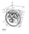
FIG. 1 shows a perspective view of a lower head of an electro-erosion machine with the spent wire guide according to the invention, -
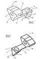
FIG. 2 shows a perspective detailed view of the spent wire guide according to the invention, -
FIG. 3 shows a perspective detailed view of the spent wire guide inFIG. 2 seen from the opposite side, -
FIG. 4 shows a further embodiment of the invention and -
FIG. 5 shows a cross section through the spent wire guide inFIG. 4 . -
FIG. 1 is an overview of a model of a lower machining head with its bonnet cover removed. This type of lower head was developed for wire electro erosion machines of the ROBOFIL- family models 240, -440 and -640. Other types of lower head corresponding to other technical requirements are also available with the ROBOFIL family as it will be seen. In our present case, thewire 2 leaves the machining zone being guided by a precision wire guide, not represented here. - The
wire 2 enters the lower head vertically along the Z-axis of thewire 2 and crosses aspent wire guide 3 having a whistle-shaped funnel portion 34 that is narrowly inserted between two cylindrical driving rollers 1. Between the precision wire guide located in the machining zone lying upstream and thespent wire guide 3, thewire 2 does not meet any obstacle. The two rollers 1 are identical and are arranged symmetrically, horizontally and in mutual contact relative to each other, touching each other at a contact line perpendicular to the Z-axis of thespent wire 2. - At the exit of the
wire guide 3, thewire 2 is immediately captured by the rollers 1 which are arranged immediately vertically downstream of thewire guide 3, which grip it and force it to progress downwards. Thefunnel portion 34 belongs to aninseparable part 3 that also includes anintermediate arm 33 and abase portion 30. Thislast base portion 30 is adjusted and fixed precisely and rigidly on a chassis plate 4 using ascrew nut 5. - In
FIG. 2 and FIG. 3 thespent wire guide 3 is shown in detail in two perspective views. The aforementionedinseparable part 3 comprises a symmetry plane which, after a correct installation inside the whole mechanical system, must pass by the line of contact between the cylinders that build the two driving rollers 1. The latter are two identical cylinders of radius e.g. 25 mm whose axes of rotation are parallel to the Y-axis. They are in contact one with the other on a line crossed perpendicularly by thewire 2. Thewire 2 gripped between the two rollers 1 is pulled by the rotation. These rollers 1 are rotated by toothed wheels 6 which gear the ones with the others according to a known technique. - The receptacle of the
conical funnel 32 has the shape of awhistle 34 whosenozzle 35 must come near the aforesaid contact line so that the wire is not likely to escape the rollers 1 laterally. The part at the origin of the invention must be accurately installed between the two rollers 1 and in their immediate proximity. It must thus reproduce in hollow the cylindrical shape of the rollers 1. In fact thewhistle 34 comprises two cylindricalconcave surfaces 36 of radius e.g. 26.5 mm which must come parallel to the rollers 1 when it is installed. The two other components of this inseparable piece i.e. theintermediate arm 33 and thebase 30, also comprise cylindricalconcave surfaces 37 which allow the passage of the toothed wheels 6 that are installed coaxially to the rollers 1. - The top diameter of the teeth of the aforementioned wheels 6 being higher than the diameter of the rollers it's the reason for which one observes a
setback 38 of approximately 1 mm between theconcave surfaces 37 of thewhistle 36 and of theintermediate arm 33. The two withdrawnconcave surfaces 37 of theintermediate arm 33 and of thebase 30 have a radius of e.g. approximately 27.5 to 28 mm. Thebase 30 itself comprises asupport face 39 perpendicular to the said symmetry plane and adrilled bore 40 crossing thesupport face 39 perpendicular to it, this last making it possible to fasten it rigidly to the mounting base 4 which receives all elements of the wire traction device. - Because of the geometry of the rollers 1, the
wire 2 can move freely according to the Y direction, all at least at the beginning when the rollers 1 are new. Later on, the friction of thewire 2 against stainless steel brings wear on the guiding surfaces at the exit of thewhistle 34. Two deep furrows, where thewire 2 is likely to be trapped, are formed in the direction Y on both sides of thenozzle 35 at the exit of thefunnel 31. The parasitic movements of thewire 2 according to Y are then reflected lower on the level of the rollers 1. - In a normal operation of the system, the
wire 2 prints a narrow and not very deep notch around the rollers 1 within the first operating hours. This notch in the rollers 1 takes part effectively in the guidance of the wire until it becomes too deep. The operator is given the possibility, approximately every 1000 machining hours, to shift or to turn over the rollers 1 so as to print a same guiding notch at a different place spaced from a few millimetres. Such operations are planned in the maintenance procedures of the machine and make it possible to prolong considerably the lifespan of the rollers 9 . - Instead of that normal operation and owing to the said early deterioration of the
funnel wire 2 is not limited in its Y excursions and digs an excessively broad and irregular furrow in the rollers 1, what can go until to make that thewire 2 escapes the capture by the rollers 1. It follows the phenomena of accumulation of wire (stuffing) in the lower head producing unpleasant interruptions and deteriorations of the installation. - The bad guidance of the
wire 2, its jerked and uncontrolled movements, produces crippling anomalies in the form of scratches on the machined surface on the part being machined. These scratches are caused by the disturbances induced on thewire 2 at the level of the rollers 1; disturbances which are reflected in the form of parasitic vibrations upstream in the machining zone. - Another disadvantage of electric nature is as follows. In this model of lower head, the machining current is conveyed by two
brush contacts 7 as seen inFIG. 1 , transmitting the current to the rollers 1, which create a perfect and stable electrical contact with thewire 2. The inevitable contacts of thewire 2 with thestainless steel guide 3 create leakage currents which unbalance the distribution of the currents on one and theother brush contacts 7. The wear of one or the other brush contacts will then be accelerated. In addition, the accidental contacts of thewire 2 with thestainless steel guide 3 modifies the impedance (self induction) of the equivalent discharge circuit thus disturbing the erosive current impulses between thewire 2 and the machined work piece. - Finally it must be quoted that the
cone funnel usual part 3, represented onFIG. 2 and 3 , a material very resistant to wear and simultaneously not conducting the electricity. - In this type of
wire guide 3 thewire 2 does not receive guidance, in the form of an electrical current contact arranged upstream of the spent wire guide, as disclosed in the above described documentEP 1 602 433 A1 . The spentwire guide 3 allows a smooth and constant rectilinear movement of thewire 2. Thewire 2 is not deflected from its vertical path by any other rollers, is always running vertically, does not need to pass any obstacles and does not undergo deflections during its evacuation. - Deflecting the
wire 2 from the vertical would inevitably introduce mechanical disturbances. On the contrary in the case of the present invention, thewire 2 enters vertically between the two rollers 1. Evacuating thewire 2 vertically eliminates a great part from the harmful disturbances to precision machining. The electrical contact that brings the current for machining is usually a major source of mechanical disturbances on thewire 2. Supplying current onto the rollers 1 reduces said disturbances. Therefore the surface quality of the work piece will be more equal and homogeneous than with other wire threading arrangements. - The operation of chopping the
wire 2 with the shocks that it produces is also a major source of mechanical disturbances. In the case of the present invention the vertical evacuation of thewire 2 makes it possible to push back the operation of chopping as far as possible off the machining zone. - The spent
wire 2 only has freedom of movement in the Y-direction and thereby could damage the surface of thewire guide 3 particularly in the region of thefunnel outlet 35. Thefunnel outlet 35 needs to provide a permanent guiding function to thewire 2. - The adopted solution represented in
FIG. 4 consists in preserving thebody 41 of thepart 3 such as designed originally out of stainless steel and to insert in it a guidingcone 42 made out of non conducting ceramics. Therefore the spentwire guide 3 will undergo less wear and will have a longer service life. Thefunnel 42 may be made of ceramics of the type having Zirconia as a base element. The option of a cast solid ceramics part was put in comparison but was not retained: too much fragile, too expensive. - The new spent
wire guide 3 is planned to withstand approximately 2000 hours. Moreover provisions are taken to let the user carry out itself the replacement. The spentwire guide 3 will be sold separately as a spare part. Thewire guide 3 will undergo less wear due to excessive abrasion. - By fixing adequate tolerances between ceramics insert 42 and
stainless steel body 41 one can leaveenough play 43 allowing sticking with glue. Such an operation is well adapted to the situation because the efforts take place to the bottom and no effort of wrenching to the top of thefunnel 31 is to be feared. Such a technique is easier to control by the manufacturer and does not require returning to a specialist. - The
body 41 is made of a stainless not hardened steel of type X10CrNiS18.9. It proved that hardened stainless steel may be vulnerable to corrosion in the present environment. The introduction of a non conducting ceramics insert allows eliminating the operation of hardening the stainless steel. - Since the spent
wire guide 3 becomes an element which the customer must replace periodically, it is envisaged to facilitate the task, i.e. to avoid tiresome adjustments. For that we envisage an execution comprising at least two pin holes in thebase portion 30 parallel with theclamp hole 40.
Claims (5)
- Spent wire guide (3) for use in an electric discharge machine suitable to be arranged downstream of the machining zone of the electric discharge machine upstream of a zone for collecting, recovering and/or further handling a spent wire (2),
immediately upstream of two identical and symmetrically arranged driving rollers (1)
arranged horizontally and in mutual contact relative to each other, so that an horizontal contact line is built, and
centrally above the two driving rollers (1),
where the spent wire guide (3) comprises a vertical symmetry plane which, when arranged in the electric discharge machine, includes the contact line of both driving rollers (1),- the spent wire guide (3) is a single inseparable piece consisting essentially of a funnel portion (34), an intermediate portion (33) and a base portion (30) forming a body,- the funnel portion (34) comprises concave surfaces (36) ending up in a whistle-shaped nozzle (35) suitable to be arranged close to the contact line of the two driving rollers (1), when mounted in the electric discharge machine are arranged- the concave surfaces (36) are arranged concentric and when mounted in the electric discharge machine are arranged coaxially with the axes of rotation of both driving rollers (1) which are arranged rotating on horizontal axes of rotation parallel to said symmetry plane,characterized in that the body (34, 33, 30) of the spent wire guide (3) is made of a stainless not hardened steel- and that the funnel portion (34) comprises a guiding cone (42) made of a non conductive ceramic. - Spent wire guide (3) according to claim 1, characterized in that the guiding cone (42) has an outside dimension smaller than the inside dimension of the funnel portion (34) thereby leaving a gap (43) in such a way that the funnel (42) may be fixed by gluing inside the funnel portion (34).
- Spent wire guide (3) according to claim 1, characterized in that the guiding cone (42) is made of a non conductive ceramic of the type having Zr as the base element.
- Spent wire guide. (3) according to claim 1, characterized in that the used stainless steel is of the type X10CrNiS18.9.
- Spent wire guide (3) as claimed according to claim 1, characterized in that at least two pin holes are bored in the base portion (30) in order to facilitate replacement and adjustment tasks.
Priority Applications (3)
| Application Number | Priority Date | Filing Date | Title |
|---|---|---|---|
| ES07103934T ES2376358T3 (en) | 2007-03-12 | 2007-03-12 | WIRE GUIDE SPENDED ON AN ELECTRICAL SHOCK MACHINE. |
| EP07103934A EP1970150B1 (en) | 2007-03-12 | 2007-03-12 | Spent wire guide for use in an electric discharge machine |
| AT07103934T ATE530285T1 (en) | 2007-03-12 | 2007-03-12 | GUIDE FOR USED WIRE FOR AN ELECTRICAL WIRE EDM MACHINE |
Applications Claiming Priority (1)
| Application Number | Priority Date | Filing Date | Title |
|---|---|---|---|
| EP07103934A EP1970150B1 (en) | 2007-03-12 | 2007-03-12 | Spent wire guide for use in an electric discharge machine |
Publications (2)
| Publication Number | Publication Date |
|---|---|
| EP1970150A1 EP1970150A1 (en) | 2008-09-17 |
| EP1970150B1 true EP1970150B1 (en) | 2011-10-26 |
Family
ID=38051376
Family Applications (1)
| Application Number | Title | Priority Date | Filing Date |
|---|---|---|---|
| EP07103934A Not-in-force EP1970150B1 (en) | 2007-03-12 | 2007-03-12 | Spent wire guide for use in an electric discharge machine |
Country Status (3)
| Country | Link |
|---|---|
| EP (1) | EP1970150B1 (en) |
| AT (1) | ATE530285T1 (en) |
| ES (1) | ES2376358T3 (en) |
Families Citing this family (1)
| Publication number | Priority date | Publication date | Assignee | Title |
|---|---|---|---|---|
| CN118699498B (en) * | 2024-07-03 | 2025-09-02 | 贵州中航拓力铸就有限责任公司 | A medium-speed wire cutting device for mold processing |
Family Cites Families (4)
| Publication number | Priority date | Publication date | Assignee | Title |
|---|---|---|---|---|
| JPS63207526A (en) * | 1987-02-19 | 1988-08-26 | Fanuc Ltd | Wire jam detecting guide for wire cut electric discharge machine |
| JP3298922B2 (en) * | 1992-04-28 | 2002-07-08 | ブラザー工業株式会社 | Wire electrode cutting device in wire electric discharge machine |
| US6011231A (en) * | 1998-02-26 | 2000-01-04 | Behnke; Michael J. | Electrode wire recovery system for electric discharge machine |
| DE10085489B4 (en) * | 2000-09-28 | 2013-05-29 | Mitsubishi Denki K.K. | Spark erosive wire cutting machine |
-
2007
- 2007-03-12 ES ES07103934T patent/ES2376358T3/en active Active
- 2007-03-12 AT AT07103934T patent/ATE530285T1/en not_active IP Right Cessation
- 2007-03-12 EP EP07103934A patent/EP1970150B1/en not_active Not-in-force
Also Published As
| Publication number | Publication date |
|---|---|
| ES2376358T3 (en) | 2012-03-13 |
| EP1970150A1 (en) | 2008-09-17 |
| ATE530285T1 (en) | 2011-11-15 |
Similar Documents
| Publication | Publication Date | Title |
|---|---|---|
| US4539459A (en) | Nozzle and power-feed element for wire-cut electrical discharge machine | |
| HK38892A (en) | Clamping device for a work piece or a tool | |
| KR20040018157A (en) | Thermal cutting processing machine and cutting method using the same | |
| US9266181B2 (en) | Head assembly for multi-wire submerged arc welding (SAW) | |
| EP1970150A1 (en) | Spent wire guide in an electric discharge machine | |
| EP2098322A1 (en) | Flushing device and method for a wire electric discharge machine | |
| CN208992482U (en) | The totally-enclosed protective hood of grinding wheel of high-speed grinding | |
| US5854459A (en) | Method and device for processing workpieces by means of electrical discharge machining | |
| KR102078001B1 (en) | Wire electrical discharge machine, wire electrical discharge machining system and jig | |
| US12128492B2 (en) | Narrow-hole electric discharge machine | |
| JPH02212025A (en) | Wire discharging machining device | |
| JP5361101B2 (en) | Wire electric discharge machine and wire electric discharge machining method | |
| JP6481806B1 (en) | Wiping apparatus and hot dipping apparatus using the same | |
| JPWO1999039859A1 (en) | Wire Electrical Discharge Machine | |
| CN221067195U (en) | Three-dimensional printer | |
| CN207289090U (en) | Rate taper device for middle wire Wire EDM equipment | |
| CA3142382A1 (en) | Device for manipulating preferably a casting tube in a changing device at the spout of a metallurgical vessel | |
| JP2002361431A (en) | Spatter removal reamer and welding torch spatter removal device using the same | |
| JP2984691B2 (en) | Arc spraying equipment | |
| CN223974205U (en) | Special laser cladding lathe bed | |
| JP2009154169A (en) | Welding torch, welding apparatus and welding method | |
| JP3518574B2 (en) | Wire electric discharge machine | |
| JPH07178623A (en) | Wire electrode guide for wire cut electric discharge machine | |
| CN210188837U (en) | A Laser Cutting Equipment That Can Improve Steel Cutting Efficiency | |
| JP7234478B2 (en) | Filler guide support structure and filler guide set including the same |
Legal Events
| Date | Code | Title | Description |
|---|---|---|---|
| PUAI | Public reference made under article 153(3) epc to a published international application that has entered the european phase |
Free format text: ORIGINAL CODE: 0009012 |
|
| AK | Designated contracting states |
Kind code of ref document: A1 Designated state(s): AT BE BG CH CY CZ DE DK EE ES FI FR GB GR HU IE IS IT LI LT LU LV MC MT NL PL PT RO SE SI SK TR |
|
| AX | Request for extension of the european patent |
Extension state: AL BA HR MK RS |
|
| RIN1 | Information on inventor provided before grant (corrected) |
Inventor name: GRANDJEAN, MICHEL MARCEL ROBERT |
|
| 17P | Request for examination filed |
Effective date: 20081007 |
|
| 17Q | First examination report despatched |
Effective date: 20081125 |
|
| AKX | Designation fees paid |
Designated state(s): AT BE BG CH CY CZ DE DK EE ES FI FR GB GR HU IE IS IT LI LT LU LV MC MT NL PL PT RO SE SI SK TR |
|
| GRAP | Despatch of communication of intention to grant a patent |
Free format text: ORIGINAL CODE: EPIDOSNIGR1 |
|
| RTI1 | Title (correction) |
Free format text: SPENT WIRE GUIDE FOR USE IN AN ELECTRIC DISCHARGE MACHINE |
|
| GRAS | Grant fee paid |
Free format text: ORIGINAL CODE: EPIDOSNIGR3 |
|
| GRAA | (expected) grant |
Free format text: ORIGINAL CODE: 0009210 |
|
| RAP1 | Party data changed (applicant data changed or rights of an application transferred) |
Owner name: AGIE CHARMILLES SA |
|
| AK | Designated contracting states |
Kind code of ref document: B1 Designated state(s): AT BE BG CH CY CZ DE DK EE ES FI FR GB GR HU IE IS IT LI LT LU LV MC MT NL PL PT RO SE SI SK TR |
|
| REG | Reference to a national code |
Ref country code: GB Ref legal event code: FG4D |
|
| REG | Reference to a national code |
Ref country code: CH Ref legal event code: EP |
|
| REG | Reference to a national code |
Ref country code: IE Ref legal event code: FG4D |
|
| REG | Reference to a national code |
Ref country code: DE Ref legal event code: R096 Ref document number: 602007018152 Country of ref document: DE Effective date: 20111222 |
|
| REG | Reference to a national code |
Ref country code: NL Ref legal event code: T3 |
|
| REG | Reference to a national code |
Ref country code: ES Ref legal event code: FG2A Ref document number: 2376358 Country of ref document: ES Kind code of ref document: T3 Effective date: 20120313 |
|
| LTIE | Lt: invalidation of european patent or patent extension |
Effective date: 20111026 |
|
| REG | Reference to a national code |
Ref country code: AT Ref legal event code: MK05 Ref document number: 530285 Country of ref document: AT Kind code of ref document: T Effective date: 20111026 |
|
| PG25 | Lapsed in a contracting state [announced via postgrant information from national office to epo] |
Ref country code: LT Free format text: LAPSE BECAUSE OF FAILURE TO SUBMIT A TRANSLATION OF THE DESCRIPTION OR TO PAY THE FEE WITHIN THE PRESCRIBED TIME-LIMIT Effective date: 20111026 Ref country code: BE Free format text: LAPSE BECAUSE OF FAILURE TO SUBMIT A TRANSLATION OF THE DESCRIPTION OR TO PAY THE FEE WITHIN THE PRESCRIBED TIME-LIMIT Effective date: 20111026 Ref country code: IS Free format text: LAPSE BECAUSE OF FAILURE TO SUBMIT A TRANSLATION OF THE DESCRIPTION OR TO PAY THE FEE WITHIN THE PRESCRIBED TIME-LIMIT Effective date: 20120226 |
|
| PG25 | Lapsed in a contracting state [announced via postgrant information from national office to epo] |
Ref country code: SE Free format text: LAPSE BECAUSE OF FAILURE TO SUBMIT A TRANSLATION OF THE DESCRIPTION OR TO PAY THE FEE WITHIN THE PRESCRIBED TIME-LIMIT Effective date: 20111026 Ref country code: SI Free format text: LAPSE BECAUSE OF FAILURE TO SUBMIT A TRANSLATION OF THE DESCRIPTION OR TO PAY THE FEE WITHIN THE PRESCRIBED TIME-LIMIT Effective date: 20111026 Ref country code: GR Free format text: LAPSE BECAUSE OF FAILURE TO SUBMIT A TRANSLATION OF THE DESCRIPTION OR TO PAY THE FEE WITHIN THE PRESCRIBED TIME-LIMIT Effective date: 20120127 Ref country code: PT Free format text: LAPSE BECAUSE OF FAILURE TO SUBMIT A TRANSLATION OF THE DESCRIPTION OR TO PAY THE FEE WITHIN THE PRESCRIBED TIME-LIMIT Effective date: 20120227 Ref country code: LV Free format text: LAPSE BECAUSE OF FAILURE TO SUBMIT A TRANSLATION OF THE DESCRIPTION OR TO PAY THE FEE WITHIN THE PRESCRIBED TIME-LIMIT Effective date: 20111026 Ref country code: PL Free format text: LAPSE BECAUSE OF FAILURE TO SUBMIT A TRANSLATION OF THE DESCRIPTION OR TO PAY THE FEE WITHIN THE PRESCRIBED TIME-LIMIT Effective date: 20111026 |
|
| PG25 | Lapsed in a contracting state [announced via postgrant information from national office to epo] |
Ref country code: CY Free format text: LAPSE BECAUSE OF FAILURE TO SUBMIT A TRANSLATION OF THE DESCRIPTION OR TO PAY THE FEE WITHIN THE PRESCRIBED TIME-LIMIT Effective date: 20111026 |
|
| PG25 | Lapsed in a contracting state [announced via postgrant information from national office to epo] |
Ref country code: BG Free format text: LAPSE BECAUSE OF FAILURE TO SUBMIT A TRANSLATION OF THE DESCRIPTION OR TO PAY THE FEE WITHIN THE PRESCRIBED TIME-LIMIT Effective date: 20120126 Ref country code: SK Free format text: LAPSE BECAUSE OF FAILURE TO SUBMIT A TRANSLATION OF THE DESCRIPTION OR TO PAY THE FEE WITHIN THE PRESCRIBED TIME-LIMIT Effective date: 20111026 Ref country code: CZ Free format text: LAPSE BECAUSE OF FAILURE TO SUBMIT A TRANSLATION OF THE DESCRIPTION OR TO PAY THE FEE WITHIN THE PRESCRIBED TIME-LIMIT Effective date: 20111026 Ref country code: EE Free format text: LAPSE BECAUSE OF FAILURE TO SUBMIT A TRANSLATION OF THE DESCRIPTION OR TO PAY THE FEE WITHIN THE PRESCRIBED TIME-LIMIT Effective date: 20111026 Ref country code: DK Free format text: LAPSE BECAUSE OF FAILURE TO SUBMIT A TRANSLATION OF THE DESCRIPTION OR TO PAY THE FEE WITHIN THE PRESCRIBED TIME-LIMIT Effective date: 20111026 |
|
| PG25 | Lapsed in a contracting state [announced via postgrant information from national office to epo] |
Ref country code: RO Free format text: LAPSE BECAUSE OF FAILURE TO SUBMIT A TRANSLATION OF THE DESCRIPTION OR TO PAY THE FEE WITHIN THE PRESCRIBED TIME-LIMIT Effective date: 20111026 |
|
| PLBE | No opposition filed within time limit |
Free format text: ORIGINAL CODE: 0009261 |
|
| STAA | Information on the status of an ep patent application or granted ep patent |
Free format text: STATUS: NO OPPOSITION FILED WITHIN TIME LIMIT |
|
| 26N | No opposition filed |
Effective date: 20120727 |
|
| PG25 | Lapsed in a contracting state [announced via postgrant information from national office to epo] |
Ref country code: MC Free format text: LAPSE BECAUSE OF NON-PAYMENT OF DUE FEES Effective date: 20120331 |
|
| REG | Reference to a national code |
Ref country code: DE Ref legal event code: R097 Ref document number: 602007018152 Country of ref document: DE Effective date: 20120727 |
|
| REG | Reference to a national code |
Ref country code: IE Ref legal event code: MM4A |
|
| PG25 | Lapsed in a contracting state [announced via postgrant information from national office to epo] |
Ref country code: AT Free format text: LAPSE BECAUSE OF FAILURE TO SUBMIT A TRANSLATION OF THE DESCRIPTION OR TO PAY THE FEE WITHIN THE PRESCRIBED TIME-LIMIT Effective date: 20111026 Ref country code: IE Free format text: LAPSE BECAUSE OF NON-PAYMENT OF DUE FEES Effective date: 20120312 |
|
| PG25 | Lapsed in a contracting state [announced via postgrant information from national office to epo] |
Ref country code: FI Free format text: LAPSE BECAUSE OF FAILURE TO SUBMIT A TRANSLATION OF THE DESCRIPTION OR TO PAY THE FEE WITHIN THE PRESCRIBED TIME-LIMIT Effective date: 20111026 |
|
| PG25 | Lapsed in a contracting state [announced via postgrant information from national office to epo] |
Ref country code: MT Free format text: LAPSE BECAUSE OF FAILURE TO SUBMIT A TRANSLATION OF THE DESCRIPTION OR TO PAY THE FEE WITHIN THE PRESCRIBED TIME-LIMIT Effective date: 20111026 |
|
| PG25 | Lapsed in a contracting state [announced via postgrant information from national office to epo] |
Ref country code: TR Free format text: LAPSE BECAUSE OF FAILURE TO SUBMIT A TRANSLATION OF THE DESCRIPTION OR TO PAY THE FEE WITHIN THE PRESCRIBED TIME-LIMIT Effective date: 20111026 |
|
| PG25 | Lapsed in a contracting state [announced via postgrant information from national office to epo] |
Ref country code: LU Free format text: LAPSE BECAUSE OF NON-PAYMENT OF DUE FEES Effective date: 20120312 |
|
| PG25 | Lapsed in a contracting state [announced via postgrant information from national office to epo] |
Ref country code: HU Free format text: LAPSE BECAUSE OF FAILURE TO SUBMIT A TRANSLATION OF THE DESCRIPTION OR TO PAY THE FEE WITHIN THE PRESCRIBED TIME-LIMIT Effective date: 20070312 |
|
| REG | Reference to a national code |
Ref country code: FR Ref legal event code: PLFP Year of fee payment: 10 |
|
| REG | Reference to a national code |
Ref country code: FR Ref legal event code: PLFP Year of fee payment: 11 |
|
| REG | Reference to a national code |
Ref country code: FR Ref legal event code: PLFP Year of fee payment: 12 |
|
| PGFP | Annual fee paid to national office [announced via postgrant information from national office to epo] |
Ref country code: DE Payment date: 20190321 Year of fee payment: 13 Ref country code: IT Payment date: 20190325 Year of fee payment: 13 Ref country code: FR Payment date: 20190322 Year of fee payment: 13 Ref country code: GB Payment date: 20190320 Year of fee payment: 13 Ref country code: CH Payment date: 20190320 Year of fee payment: 13 |
|
| PGFP | Annual fee paid to national office [announced via postgrant information from national office to epo] |
Ref country code: NL Payment date: 20190320 Year of fee payment: 13 Ref country code: DE Payment date: 20190321 Year of fee payment: 13 |
|
| PGFP | Annual fee paid to national office [announced via postgrant information from national office to epo] |
Ref country code: ES Payment date: 20190418 Year of fee payment: 13 |
|
| REG | Reference to a national code |
Ref country code: DE Ref legal event code: R119 Ref document number: 602007018152 Country of ref document: DE |
|
| REG | Reference to a national code |
Ref country code: CH Ref legal event code: PL |
|
| REG | Reference to a national code |
Ref country code: NL Ref legal event code: MM Effective date: 20200401 |
|
| PG25 | Lapsed in a contracting state [announced via postgrant information from national office to epo] |
Ref country code: NL Free format text: LAPSE BECAUSE OF NON-PAYMENT OF DUE FEES Effective date: 20200401 |
|
| PG25 | Lapsed in a contracting state [announced via postgrant information from national office to epo] |
Ref country code: DE Free format text: LAPSE BECAUSE OF NON-PAYMENT OF DUE FEES Effective date: 20201001 Ref country code: CH Free format text: LAPSE BECAUSE OF NON-PAYMENT OF DUE FEES Effective date: 20200331 Ref country code: LI Free format text: LAPSE BECAUSE OF NON-PAYMENT OF DUE FEES Effective date: 20200331 Ref country code: FR Free format text: LAPSE BECAUSE OF NON-PAYMENT OF DUE FEES Effective date: 20200331 |
|
| GBPC | Gb: european patent ceased through non-payment of renewal fee |
Effective date: 20200312 |
|
| PG25 | Lapsed in a contracting state [announced via postgrant information from national office to epo] |
Ref country code: GB Free format text: LAPSE BECAUSE OF NON-PAYMENT OF DUE FEES Effective date: 20200312 |
|
| REG | Reference to a national code |
Ref country code: ES Ref legal event code: FD2A Effective date: 20210729 |
|
| PG25 | Lapsed in a contracting state [announced via postgrant information from national office to epo] |
Ref country code: IT Free format text: LAPSE BECAUSE OF NON-PAYMENT OF DUE FEES Effective date: 20200312 |
|
| PG25 | Lapsed in a contracting state [announced via postgrant information from national office to epo] |
Ref country code: ES Free format text: LAPSE BECAUSE OF NON-PAYMENT OF DUE FEES Effective date: 20200313 |