EP1969922B1 - Intelligenter Wasserzeitmesser - Google Patents
Intelligenter Wasserzeitmesser Download PDFInfo
- Publication number
- EP1969922B1 EP1969922B1 EP08405076.4A EP08405076A EP1969922B1 EP 1969922 B1 EP1969922 B1 EP 1969922B1 EP 08405076 A EP08405076 A EP 08405076A EP 1969922 B1 EP1969922 B1 EP 1969922B1
- Authority
- EP
- European Patent Office
- Prior art keywords
- soil moisture
- water timer
- soil
- water
- sensing unit
- Prior art date
- Legal status (The legal status is an assumption and is not a legal conclusion. Google has not performed a legal analysis and makes no representation as to the accuracy of the status listed.)
- Not-in-force
Links
Images




Classifications
-
- A—HUMAN NECESSITIES
- A01—AGRICULTURE; FORESTRY; ANIMAL HUSBANDRY; HUNTING; TRAPPING; FISHING
- A01G—HORTICULTURE; CULTIVATION OF VEGETABLES, FLOWERS, RICE, FRUIT, VINES, HOPS OR SEAWEED; FORESTRY; WATERING
- A01G25/00—Watering gardens, fields, sports grounds or the like
- A01G25/16—Control of watering
- A01G25/167—Control by humidity of the soil itself or of devices simulating soil or of the atmosphere; Soil humidity sensors
-
- Y—GENERAL TAGGING OF NEW TECHNOLOGICAL DEVELOPMENTS; GENERAL TAGGING OF CROSS-SECTIONAL TECHNOLOGIES SPANNING OVER SEVERAL SECTIONS OF THE IPC; TECHNICAL SUBJECTS COVERED BY FORMER USPC CROSS-REFERENCE ART COLLECTIONS [XRACs] AND DIGESTS
- Y10—TECHNICAL SUBJECTS COVERED BY FORMER USPC
- Y10T—TECHNICAL SUBJECTS COVERED BY FORMER US CLASSIFICATION
- Y10T137/00—Fluid handling
- Y10T137/1842—Ambient condition change responsive
- Y10T137/1866—For controlling soil irrigation
- Y10T137/189—Soil moisture sensing
-
- Y—GENERAL TAGGING OF NEW TECHNOLOGICAL DEVELOPMENTS; GENERAL TAGGING OF CROSS-SECTIONAL TECHNOLOGIES SPANNING OVER SEVERAL SECTIONS OF THE IPC; TECHNICAL SUBJECTS COVERED BY FORMER USPC CROSS-REFERENCE ART COLLECTIONS [XRACs] AND DIGESTS
- Y10—TECHNICAL SUBJECTS COVERED BY FORMER USPC
- Y10T—TECHNICAL SUBJECTS COVERED BY FORMER US CLASSIFICATION
- Y10T137/00—Fluid handling
- Y10T137/8593—Systems
- Y10T137/86389—Programmer or timer
Definitions
- programmable timers In the area of lawn watering, lawn sprinklers have been known and used for years. For example, square oscillating sprinklers have been used along with a water hose to water a given area of lawn. To make watering a lawn more convenient, programmable timers have also been known. A programmable timer can be used to set the time at which the lawn is to be watered. In a typical setup, a programmable timer is connected to a water source on one end and a hose, which is connected to a lawn sprinkler, on the other end. A user could then program or set the water timer, and the lawn sprinkler would come on at the pre-designated time intervals.
- the smart water timer comprises a water timer, a receiving unit, and a moisture sensing unit which is in wireless communication with the receiving unit.
- the receiving unit is also in communication with the water timer.
- a moisture sensing unit measures the soil moisture content of a soil and transmits a message to the receiving unit indicating whether or not the timer should be allowed to be in an "on" state; that is, be in a state where the timer is allowed to open its water valve, thereby turning on a lawn sprinkler. If the moisture level of the soil is higher than the moisture level threshold (or moisture range) previously selected by a user, then the soil moisture sensor will transmit a message to the receiving unit indicating that the water timer should turn off (if the water timer is already on), or not turn on at all. If the moisture level of the soil is lower than the moisture level threshold previously selected by a user, then the soil moisture sensor will transmit a message to the receiving unit indicating that it is ok for the water timer to turn on.
- the moisture level threshold or moisture range
- the water timer can have a plurality of water valves, each one of which can be associated with a different soil moisture sensor.
- the water timer can also be configured to have a receiving unit built into the timer. This reduces the number of parts needed for the smart water timer system.
- the soil moisture sensing unit includes a soil moisture sensor, a transmitter or transceiver which is in communication with the receiving unit and an adjustment mechanism (selection means) which allows a user to select a desired soil moisture content of the soil.
- the soil moisture sensor may be of a capacitive variety, although other types of sensors will also work.
- the transmitter or transceiver of the soil moisture sensor can transmit a radio wave to the receiving unit, which has a receiver or transceiver, indicating whether or not the soil needs more water.
- the soil moisture sensor can also have a display means, such an LED or the like.
- Fig. 1 is a system view of a first embodiment of a smart water timer system 1.
- Smart water timer system 1 comprises water timer 60, receiving unit 100 and soil moisture sensing unit 20.
- Soil moisture sensing unit 20 is shown positioned in the ground within a signal transmitting proximity (e.g. within 200 feet or 60,96 meter) of receiving unit 100, which is in communication with water timer 60.
- water timer 60 is connected to water source 160.
- Water source 160 connects to an input of water timer 60.
- a garden hose 150 connects the output of water timer 60 to an input of a conventional lawn sprinkler 140.
- any lawn watering device may be used such as a rotary sprinkler, bubbler, drip line, etc.
- Water timer 60 is programmed to turn on the oscillating lawn sprinkler 140 at a scheduled interval(s) (e.g. the water timer is "on” during a watering cycle and "off” between watering cycles).
- Soil moisture sensing unit 20 is positioned on the lawn or area to be watered. Preferably, to obtain a more accurate reading, the soil moisture sensing unit 20 is placed in a position close to the desired watering area.
- the soil moisture sensing unit 20 is set by a user (described later), to a desired soil moisture level, and transmits a signal to receiving unit 100, based on the desired soil moisture level selected by the user.
- the receiving unit 100 receives the signal and sends the signal to water timer 60.
- Water timer 60 determines whether or not to open a water valve (e.g., turn on a water supply and thus sprinkler 140), based on the predetermined timer settings and the soil moisture signal received from the soil moisture sensing unit 20.
- Figs. 2 and 3 illustrate front and rear perspective views of soil moisture sensor 20, respectively.
- Soil moisture sensor housing 22 contains soil moisture sensor control module 31.
- Housing 22 includes top portion 23 and bottom or lower portion 32a.
- Top portion 23 contains the logic elements of soil moisture sensing unit 20, while bottom portion 32a contains the sensor portion of soil moisture sensing unit 20.
- a moisture level switch 24 is located on an outside surface of top portion 23 and allows a user to turn on and select a desired moisture level or range for the soil. For example, a user may adjust control knob 24a to any one of a number of positions, e.g., indicated by adjustment setting positions 26.
- Fig. 2 illustrates a control knob and switch (to select the desired level of moisture), it is generally known that any suitable mechanism which allows for setting the desired moisture level is acceptable. Such a mechanism could include buttons, levers, touch sensors, etc.
- Adjustment setting positions 26 may be, for example, off, low, medium and high. However, adjustment setting positions 26 may also include more or less setting positions. In this embodiment, a low setting indicates that a low level of moisture is desired in the soil, a medium setting indicates that a medium level of moisture is desired in the soil, and a high setting indicates that a high level of moisture is desired in the soil.
- soil moisture probe 34 comprises printed wire board 21 and printed wire board traces 27.
- Printed wire traces 27 form a capacitor.
- printed wire traces 27 are covered with a water resistant protective layer (not shown), such as plastic or any other suitable material. This prevents the printed wire traces 27 from coming in physical contact with the soil and water, thereby extending the life of the capacitive soil moisture probe 34.
- Printed wire traces 27 may be formed from copper, platinum or any other suitable conductor. In an alternative embodiment, printed wire traces 27 may be replaced by conductive pads which act as electrodes in the capacitive soil moisture sensor.
- printed wire traces 27 may be positioned in a horizontal (not shown) as opposed to vertical manner as shown in Figs. 2 and 3 . This allows the soil moisture probe 34 to determine the moisture of the soil at a desired depth. Thus, for example if the user wanted the soil located in the top part of the ground to have a certain moisture level, the user could simply push in the moisture sensor 20 to a desired depth, allowing the soil moisture probe 34 to operate at the appropriate depth.
- the capacitive soil moisture probe 34 works in a simple manner.
- the soil has a low dielectric constant.
- the dielectric constant of the soil increases due to the increase of water in the soil.
- the dielectric constant of the soil also increases, which results in a higher capacitance of the capacitor.
- the capacitance of the soil moisture probe 34 indicates the moisture content of the soil.
- Printed wire board 21 is shown housed in lower portion 32a.
- Lower portion 32a may be configured to have a tapered or spiked end 28 (opposing top portion 23) which allows the printed wire board 21 to be inserted into the soil using its pointed tip, without damaging printed wire board 21.
- lower portion 32a may also have a rounded end.
- Support rib 25, shown in Fig. 3 gives structural support to lower portion 32a.
- top portion 23 includes power module compartment 30.
- Power module compartment 30 is designed to be water tight. Power module compartment 30 may contain batteries, a solar cell or any other system to power moisture sensing unit sensor 20.
- Soil moisture sensor housing 22 is configured to include a water tight seal.
- Soil moisture sensor housing 22 may be molded of a polymeric material having requisite strength and durability for service under the conditions to be described below.
- an ultrasonic welding technique is used when assembling housing 22 in order to seal the internal components, but any other suitable technique such as using seals, gaskets, screws and chemical fasteners, such as epoxy, may also be used.
- a block diagram of soil moisture sensor control module 31 is shown in Fig. 4 .
- the operation of the soil moisture sensor control module 31 is described below.
- a capacitance probe 34 measures the capacitance of the soil. The measured value is input into controller 39.
- Controller 39 may be a microprocessor such as Texas Instruments Controller MSP430F2011, or any other suitable device.
- Controller 39 receives the selected moisture level input, determined from moisture level switch 24 (described above). Controller 39 compares the data received from the capacitance probe 34 and moisture level input determined from the moisture level switch 24. If controller 39 determines that there is too much moisture in the soil, then controller 39 instructs the transmitter 32 to send a signal to the water timer 60, for example, indicating that it should turn off or remain off.
- Each different switch setting of moisture level switch 24 may be connected to a different combination of inputs of controller 39. If a low level of moisture is selected, this will be connected to a specific input(s) of controller 39. If a medium level of moisture is selected, this will be connected to a different input(s) of controller 39. If a high level of moisture is selected, this will be connected to a different input(s) of controller 39. This allows controller 39 to determine the desired moisture setting.
- adjustment setting positions 26 there are four adjustment setting positions 26 (shown in Fig. 2 , i.e.,off, low, medium and high).
- the value indicated by the moisture level switch 24 is based on a preset scale. However, if the moisture level switch is set to the off position, then the soil moisture sensing unit 20 does not operate and a signal is never sent to water timer 60. As discussed later, the water timer 60 then operates in default mode and does not receive any input from receiving unit 100.
- the moisture level switch 24 is set to "low,” then the water in the soil is desired to be approximately between 25% and 45% by weight, (on a scale of 0% to 100%, wherein 0% is no water in the soil and 100% is total water). If the moisture level switch 24 is set to "medium,” then the water in the soil is desired to be between 50% and 70% by weight. If the moisture level switch 24 is set to "high,” then the water in the soil is desired to be between 70% and 90% by weight. It is noted that these set values may be changed to any particular values and are not limited to the ones recited above.
- a signal is transmitted to receiver 60. This is done with transmitter 32.
- Transmitter 32 is connected to controller 39 and may be, for example, an Integration Association FSK IA 4221 transmitter. Other appropriate transmitters or transceivers may also be used.
- a crystal oscillator 35 may also be used in conjunction with transmitter 32.
- Antenna 36 is used to improve the gain of the transmitted signal.
- Power supply module 37 powers the soil moisture sensor control module 31.
- a transmitter and receiver may be paired together so that they operate on the same frequency. This pairing may be done at the place the units are made. This way, a user may simply install and power-up the units and they will recognize each other as they are both paired together. This avoids interference with other units used within an overlapping transmitting proximity.
- the transmitter 32 may have an RF selection switch (not shown), in which a particular broadcast frequency may be chosen. This could help ensure that if two broadcast unit are operating in an overlapping broadcast area, the signals would not interfere with each other as the RF switch on each unit could be set to transmit on a different frequency.
- Step 1 begins the process with a power-up state.
- step 2 the software of the transmitter is reset.
- step 3 the transmitter synchronizes with the receiving unit 100.
- the synchronization step allows the receiving unit 100 and water timer 60 to prepare for an incoming data message.
- step 4 a data message is transmitted.
- the transmitted message may for example last for approximately 200 ms (with some wait-time occurring between the synchronization step and the data message transmission).
- the transmitted message could be as simple as a yes or no; that is, allow the timer to come on, or not allow the timer to come on.
- This simple yes or no, on or off message allows for a brief period of transmission time. That is, very few data bits need to be sent. In fact, a minimum of 1 data bit may be sent; a simple 1 or 0 representing on or off.
- the on or off signal indicates whether or not the timer should be allowed to turn on, or if the timer is already on, whether or not the timer should turn off. This saves power and promotes battery life. Transmitting a moisture value of the soil can also be used, but requires transmitting much more data, thereby increasing transmission time. Furthermore, with this increase in transmission time, more transmission energy will be used, thereby shortening battery life.
- the transmitter After the message has been transmitted, the transmitter enters a 15 second sleep mode in step 5 (e.g., it is known that the sleep mode can be set to more or less than 15 seconds). Thus, the transmitter may only transmit for approximately 200 ms out of every 15 seconds. This amounts to the transmitter transmitting for only 1.33% of the time. This allows the transmitter to conserve energy and battery power. As such, the battery life of battery 31 can be greatly extended.
- a 15 second sleep mode e.g., it is known that the sleep mode can be set to more or less than 15 seconds.
- the transmitter may only transmit for approximately 200 ms out of every 15 seconds. This amounts to the transmitter transmitting for only 1.33% of the time. This allows the transmitter to conserve energy and battery power. As such, the battery life of battery 31 can be greatly extended.
- transmitter 32 wakes up in step 6 and increments an event counter.
- a decision is made as to whether or not the event counter has reached 125. If the event counter has reached 125, the process repeats again, starting from step 2. If the event counter has not reached 125, the process repeats again starting from step 3.
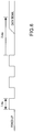
- Fig. 6 is a timing diagram of a transmitted signal from transmitter 32. As shown in Fig. 6 , upon power-up of the transmitter 32, three 1 ms pulses are sent. This allows the transmitter 32 and receiver 114 (described later) to synchronize. Next, after a predetermined amount of time, a data signal is sent to the receiver 114. The data signal indicates whether or not the water timer 60 should be allowed to turn on. For example, if the user selected a low moisture setting and the soil is moist, then soil moisture sensor 20 will transmit a signal indicating that water timer 60 should not be allowed to turn on.
- soil moisture sensor 20 will transmit a signal indicating that the water timer 60 should be allowed to turn on a water supply.
- Moisture receiving unit 100 is shown in Fig. 7 .
- Receiver housing 102 includes clip 108 attached to it so that it can be coupled to water timer 60.
- Receiver cable 104 attaches connector 106 to housing 102 and receiver module 110 (shown in Fig. 8 ).
- Connector 106 attaches to timer 60, specifically at input port 70 (shown in Fig. 9 ).
- Receiver controller 112 is connected to receiver 114.
- Receiver 114 may be, for example IA4320FSK receiver made by Integration Associates, although other receivers or transceivers known in the art will also work.
- Receiver controller 112 is also connected to connector 106, which attaches to water timer 60 (described later). As discussed above, a receiver and transmitter may be paired together. This allows a user to more easily set up and install a smart water timer because once the units are powered-up, the receiver module 110 automatically recognizes the signal sent by soil moisture sensor 20.
- a receiver RF channel selection switch may also be used (not shown) to select a frequency in which to communicate with transmitter 32.
- the receiver module 110 should be set to receive the same channel as the channel selected to be broadcast in the soil moisture sensor control module 31.
- Receiver 114 receives a signal transmitted from the transmitter 32 located in the soil moisture sensor 20. Antenna 116 is used in conjunction with receiver 114 in order to increase the amplitude of the signal received from transmitter 32. Upon receiving a signal, receiver 114 processes the signal and transmits the signal information to receiver controller 112. For example, when the soil moisture sensor unit transmits a signal, a series of three, 1 ms pulses are generated. After the pulses are sent, a pre-determined period of time passes and the data signal is sent.
- Receiver cable 104 has three (3) channels, a data channel, a power channel, and a ground channel.
- the power channel supplies 3.3 VDC power to receiving unit 100.
- the data channel transmits the data received from the soil moisture sensor 20. Data is passed through receiver cable 104 to receiver connector 106. Receiver connector 106 plugs into input port 70 of water timer 60.
- Receiving unit 100 includes receiver clip 108, which allows a stable connection to water timer 60.
- receiver clip 108 allows a stable connection to water timer 60.
- a user in order to set up receiving unit 100 with water timer 60, a user must only plug receiver connector 106 into input port 70 and attach receiver clip 108 to water timer 60. This allows for a quick and easy installment process.
- receiving unit 100 may be built in, or integrated with, water timer 60.
- the water timer and receiver could be one integral unit, reducing manufacturing cost.
- One drawback of this feature is the higher cost for the water timer 60 because receiving unit 100 would also be part of the unit.
- a receiving unit 100 could operate by receiving multiple inputs from multiple soil moisture sensing units 20. For example, a user may want to place two or more soil moisture sensors 20 in the lawn. If one of the probes indicates the moisture of the soil is higher than a selected value, a signal would be sent to water timer 60 to not allow watering of the lawn.
- the receiving unit 100 is thus capable of accepting a plurality of signals from various soil moisture sensors. As such, receiving unit 100 could also control multiple valves of water timer 60, allowing asynchronous watering of an area to be watered.
- Fig. 9 shows a water timer 60.
- a water timer could be for example, Melnor Electronic AquaTimerTM 3015 or Melnor Electronic AquaTimerTM 3060.
- Water timer 60 has a water inlet 62 and a water outlet 72. Water inlet 62 is connected to a water source 160 (shown in Fig. 1 ) and water outlet 72 is typically connected to a garden hose which is in turn connected to a watering device such as sprinkler 140.
- Water timer 60 also has control buttons 68 in order to set and operate the water timer 60, as well as a display 64.
- the display 64 may be a light emitting diode display (LED), liquid crystal display (LCD), organic light emitting diode (OLED) or any other suitable display.
- Water timer 60 is housed in a timer housing 66.
- Water timer 60 also has an input port 70 for receiving connector 106 from receiving unit 100. This allows communication between water timer 60 and receiving unit 100.
- Fig. 10 shows how water timer 60 operates when connected to receiving unit 100.
- Step 20 shows a power up state when the water timer 60 is turned on. When water timer 60 is powered-up, power is also sent to receiving unit 100 via the power channel in receiver cable 104.
- step 21 water timer 60 goes through a device configuration and in step 22, synchronizes with receiving unit 100. Once the receiving unit 100 synchronizes with water timer 60, the water timer 60 enters a listening mode in step 23.
- the water timer 60 determines whether or not a message has been received from the receiving unit 100. In the listening mode, the water timer 60 checks the status of any received message immediately before a watering cycle is about to begin or during the watering cycle itself (e.g., between 1 minute and 1 ns before the water timer is scheduled to come on). If no message is received, the water timer 60 goes into a default mode in step 28. In default mode, the water timer 60 operates without any input from soil moisture sensing unit 20, or receiving unit 100. In other words, water timer 60 turns on a water supply when the timer indicates it is appropriate to do so. An image of a flashing antenna may also be displayed, indicating no signal from soil moisture sensing unit 20 has been received.
- water timer 60 Once water timer 60 finishes watering, it will then look for a signal from receiving unit 100 indicating a data signal from soil moisture sensing unit 20, shown in step 29. If no signal is received, water timer 60 will again enter a default mode and continue operating without any input from the soil moisture sensing unit 20, as shown in step 28.
- step 25 a moisture status register is updated indicting the moisture status of the soil.
- step 26 the water timer status is updated to reflect the moisture status of the soil.
- Water timer 60 checks the status of the received data from the soil moisture sensing unit 20 once every five minutes, while the water timer 60 is in a watering cycle. Water timer 60 checks once every five minutes for two of the following reasons. First, is that if soil moisture sensing unit 20 indicates that the moisture of the soil has reached the desired value while the sprinkler 140 is watering the lawn, water timer 60 can turn off the water supply, thereby turning off the sprinkler 140. Thus, if a rainstorm starts after the sprinkler 140 comes on, the smart water timer 1 can still turn off the water supply and the sprinkler after receiving the status of the soil moisture, no later than 5 minutes after the sprinkler has turned on.
- the water timer 60 does not check the status of the data signal too often, in order to conserve power.
- the inventors have set the water timer to check once every 5 minutes if the water timer is on, but this time interval can of course be varied.
- a timer 60 may have multiple output valves. These output valves may also be programmable. Such a timer could be used, for example, with multiple soil moisture sensing units 20. Each sensing unit could be placed in a different part of an area to be watered and indicate a different desired moisture level.
- one soil moisture sensing unit could be placed in a lawn, another in a tomato garden and another in a flower garden.
- Each soil moisture sensing unit could be affiliated with a different programmable valve of water timer 60 and have its own affiliated sprinkler. This would allow the user to customize the desired soil moisture level of each area to be watered, all based on a single water source and valve.
Landscapes
- Life Sciences & Earth Sciences (AREA)
- Soil Sciences (AREA)
- Engineering & Computer Science (AREA)
- Water Supply & Treatment (AREA)
- Environmental Sciences (AREA)
- Investigating Or Analyzing Materials By The Use Of Electric Means (AREA)
Claims (18)
- Intelligentes Wasser-Zeitgebersystem (1) zum Steuern einer auf eine Rasenfläche ausgegebenen Wassermenge, wobei das intelligente Wasser-Zeitgebersystem (1) Folgendes umfasst:eine Steuereinheit (60) zum Öffnen und Schließen eines Wasserventils;eine Empfangseinheit (100) in Kommunikation mit der Steuereinheit (60); undeine Feuchtigkeitserfassungseinheit (20) in drahtloser Kommunikation mit der Empfangseinheit (100); wobeidie Feuchtigkeitserfassungseinheit (20) ein Auswahlmittel (24) für einen Anwender, damit er einen gewünschten Erdreichfeuchtigkeitsbereich auswählen kann, enthält, wobeidie Steuereinheit (60) ein Wasserzeitgeber ist und das Wasserventil in dem Wasserzeitgeber angeordnet ist, wobei der Wasserzeitgeber einen Wassereinlass und einen Wasserauslass für die Verbindung mit einem Rasensprenger (140) umfasst,der Wasserzeitgeber so programmiert ist, dass er in einem oder in mehreren zeitlich geplanten Intervallen für die Bewässerung der Rasenfläche eingeschaltet wird, undein Sender (32) der Feuchtigkeitseinheit (20) konfiguriert ist, ein Signal zu dem Wasserzeitgeber zu senden, um ihn auszuschalten oder ausgeschaltet zu lassen.
- Intelligentes Wasser-Zeitgebersystem (1) nach Anspruch 1, wobei die Feuchtigkeitserfassungseinheit (20) in vorgegebenen Zeitintervallen einen Erdreichfeuchtigkeitsgehalt misst und eine Nachricht an die Empfangseinheit (100) sendet.
- Intelligentes Wasser-Zeitgebersystem (1) nach Anspruch 1,
wobei die Empfangseinheit konfiguriert ist, mehrere Eingangssignale von mehreren Erdreichfeuchtigkeitserfassungseinheiten zu empfangen und/oder mehrere Ventile in dem Wasserzeitgeber zu steuern. - Intelligentes Wasser-Zeitgebersystem (1) nach Anspruch 1, wobei die Empfangseinheit (100) und die Steuereinheit (60) modulare Einheiten sind.
- Intelligentes Wasser-Zeitgebersystem (1) nach Anspruch 1, wobei das intelligente Wasser-Zeitgebersystem (1) ferner eine Rasenflächen-Bewässerungsvorrichtung (140) umfasst, die mit der Steuereinheit (60) betriebstechnisch verbunden ist.
- Intelligentes Wasser-Zeitgebersystem (1) nach Anspruch 1, wobei die Feuchtigkeitserfassungseinheit (20) einen Erdreichfeuchtigkeitsgehalt von Erdreich misst und eine Datennachricht, die angibt, ob der Steuereinheit (60) erlaubt werden sollte, eine Rasenflächen-Bewässerungsvorrichtung (140) einzuschalten, an die Empfangseinheit (100) sendet.
- Intelligentes Wasser-Zeitgebersystem (1) nach Anspruch 6, wobei die Datennachricht nur ein Bit enthält.
- Intelligentes Wasser-Zeitgebersystem (1) nach Anspruch 1, wobei die Feuchtigkeitserfassungseinheit (20) einen kapazitiven Erdreichfeuchtigkeitssensor (34) enthält.
- Intelligentes Wasser-Zeitgebersystem (1) nach Anspruch 1, wobei die Steuereinheit (60) mehrere Auslassventile besitzt.
- Intelligentes Wasser-Zeitgebersystem (1) nach Anspruch 1, wobei zusammen mit der Steuereinheit (60) mehrere Feuchtigkeitserfassungseinheiten (20) verwendet werden, derart, dass den mehreren Auslassventilen mehrere Feuchtigkeitserfassungseinheiten (20) entsprechen.
- Erdreichfeuchtigkeit-Erfassungseinheit (20), die Folgendes umfasst:ein Gehäuse (22);einen Feuchtigkeitssensor (34), der in Kommunikation mit dem Erdreich anzuordnen ist;einen drahtlosen Sender (32) in Kommunikation mit dem Erdreichfeuchtigkeitssensor; undeinen Einstellmechanismus, um einen gewünschten Erdreichfeuchtigkeitsbereich des Erdreichs auszuwählen, wobei der Einstellmechanismus mit dem Erdreichfeuchtigkeitssensor kommuniziert, wobeidie Erdreichfeuchtigkeit-Erfassungseinheit (20) eine Steuereinheit (39) für die Bestimmung, ob das Erdreich zu feucht ist, umfasst, die mit dem Sender (32) verbunden ist, wobei der drahtlose Sender (32) konfiguriert ist, i) mit einer Empfangseinheit (100) zu synchronisieren, die in einen Wasserzeitgeber (60) integriert ist oder damit kommuniziert, um der Empfangseinheit (100) und dem Wasserzeitgeber (60) zu erlauben, eine eingehende Datennachricht vorzubereiten, ii) entweder eine Ja- oder eine Nein-Datennachricht, die wenige Bits enthält, zu senden, um dem Wasserzeitgeber (60) ein Einschalten zu erlauben oder um dem Wasserzeitgeber ein Einschalten nicht zu erlauben, und iii) nach dem Senden der Ja- oder der Nein-Datennachricht in einen Ruhemodus einzutreten, um Energie zu sparen, undwobei der Einstellmechanismus einen Feuchtigkeitsbereichsschalter aufweist, der in eine Aus-Position versetzt werden kann, in der die Feuchtigkeitserfassungseinheit (20) nicht arbeitet und keine Datennachricht zu dem Wasserzeitgeber (60) gesendet wird.
- Erdreichfeuchtigkeit-Erfassungseinheit (20) nach Anspruch 11, wobei die Erdreichfeuchtigkeit-Erfassungseinheit (20) Eingangsdaten von dem Erdreichfeuchtigkeitssensor (34) mit Eingangsdaten von dem Auswahlmittel (24) vergleicht und bestimmt, ob das Erdreich über dem ausgewählten gewünschten Erdreichfeuchtigkeitsbereich liegt oder nicht.
- Erdreichfeuchtigkeit-Erfassungseinheit (20) nach Anspruch 11, wobei ein Sender (32) eine Datennachricht sendet, die angibt, dass eine Erdreichfeuchtigkeit höher oder niedriger als ein Höchstwert des mit dem Auswahlmittel (24) ausgewählten gewünschten Erdreichfeuchtigkeitsbereichs ist.
- Erdreichfeuchtigkeit-Erfassungseinheit (20) nach Anspruch 11, wobei der Erdreichfeuchtigkeitssensor eine kapazitive Sonde (34) ist.
- Erdreichfeuchtigkeit-Erfassungseinheit (20) nach Anspruch 14, wobei die kapazitive Sonde (34) Leiterbahnen (27) aufweist, die auf einer gedruckten Leiterplatte (21) gebildet sind.
- Erdreichfeuchtigkeit-Erfassungseinheit (20) nach Anspruch 14, wobei die kapazitive Sonde (34) Elektroden (27) aufweist, die im Allgemeinen horizontal in Bezug auf das Erdreich positioniert sind.
- Erdreichfeuchtigkeit-Erfassungseinheit (20) nach Anspruch 11, wobei das Auswahlmittel (24) ein Drehschalter ist.
- Verfahren zum Verwenden eines intelligenten Wasser-Zeitgebersystems (1) nach einem der Ansprüche 1 bis 10, wobei das intelligente Wasser-Zeitgebersystem (1) Folgendes umfasst:eine Steuereinheit (60) zum Öffnen und Schließen eines Wasserventils, wobei die Steuereinheit (60) ein Wasserzeitgeber ist und das Wasserventil in dem Wasserzeitgeber angeordnet ist;eine Empfangseinheit (100) in Kommunikation mit der Steuereinheit (60); undeine Feuchtigkeitserfassungseinheit (20) in drahtloser Kommunikation mit der Empfangseinheit (100); wobei die Feuchtigkeitserfassungseinheit (20) ein Auswahlmittel (24) für einen Anwender, damit er einen gewünschten Erdreichfeuchtigkeitsbereich auswählen kann, umfasst,wobei das Verfahren die folgenden Schritte umfasst:Festlegen eines gewünschten Erdreichfeuchtigkeitsbereichs bei einer Erdreichfeuchtigkeit-Erfassungseinheit (20); undAnordnen der Erdreichfeuchtigkeit-Erfassungseinheit (20) in dem zu erfassenden Bereich, wobeidie Erdreichfeuchtigkeit-Erfassungseinheit ein Datensignal drahtlos an die Empfangseinheit sendet undeine Empfangseinheit (100) eine drahtlose Datennachricht, die angibt, ob der Wasserzeitgeber (60) ausgeschaltet werden oder ausgeschaltet bleiben sollte, zu einem Wasserzeitgeber (60) weiterleitet.
Applications Claiming Priority (2)
| Application Number | Priority Date | Filing Date | Title |
|---|---|---|---|
| US90681907P | 2007-03-14 | 2007-03-14 | |
| US94276307P | 2007-06-08 | 2007-06-08 |
Publications (2)
| Publication Number | Publication Date |
|---|---|
| EP1969922A1 EP1969922A1 (de) | 2008-09-17 |
| EP1969922B1 true EP1969922B1 (de) | 2020-09-16 |
Family
ID=39537912
Family Applications (1)
| Application Number | Title | Priority Date | Filing Date |
|---|---|---|---|
| EP08405076.4A Not-in-force EP1969922B1 (de) | 2007-03-14 | 2008-03-14 | Intelligenter Wasserzeitmesser |
Country Status (6)
| Country | Link |
|---|---|
| US (1) | US7810515B2 (de) |
| EP (1) | EP1969922B1 (de) |
| AU (1) | AU2008201164B2 (de) |
| CA (1) | CA2625686C (de) |
| ES (1) | ES2836217T3 (de) |
| PT (1) | PT1969922T (de) |
Families Citing this family (41)
| Publication number | Priority date | Publication date | Assignee | Title |
|---|---|---|---|---|
| US8620480B2 (en) | 2003-04-25 | 2013-12-31 | George Alexanian | Irrigation water conservation with automated water budgeting and time of use technology |
| US8538592B2 (en) | 2003-04-25 | 2013-09-17 | George Alexanian | Landscape irrigation management with automated water budget and seasonal adjust, and automated implementation of watering restrictions |
| US8219254B2 (en) * | 2006-11-20 | 2012-07-10 | Water Optimizer LLC. | Adaptive control for irrigation system |
| US20090177330A1 (en) * | 2007-12-20 | 2009-07-09 | Kah Jr Carl L C | Wireless moisture probe, receiving controller and irrigation control system |
| US9022300B2 (en) | 2008-03-14 | 2015-05-05 | Melnor, Inc. | Vertical rising sprinkler apparatus with stabilized base unit |
| USD604189S1 (en) * | 2008-12-30 | 2009-11-17 | Robert Bosch Gmbh | Front face of an electronic water timer |
| USD604190S1 (en) * | 2008-12-30 | 2009-11-17 | Robert Bosch Gmbh | Front face of an electronic water timer |
| US20100179701A1 (en) * | 2009-01-13 | 2010-07-15 | At&T Intellectual Property I, L.P. | Irrigation system with wireless control |
| USD607847S1 (en) * | 2009-03-10 | 2010-01-12 | Hunter Industries, Inc. | Wireless irrigation transmitter |
| US8245985B2 (en) * | 2009-04-24 | 2012-08-21 | Robert Bosch Gmbh | Hose hanger device |
| USD636278S1 (en) * | 2009-12-23 | 2011-04-19 | Claber S.P.A. | Timer for two way solenoid valve |
| US10232395B2 (en) | 2010-07-19 | 2019-03-19 | Irrigreen, Inc. | Multi-nozzle rotary sprinkler |
| US9007050B2 (en) | 2010-09-17 | 2015-04-14 | The Toro Company | Soil moisture sensor with improved enclosure |
| USD642077S1 (en) * | 2010-11-23 | 2011-07-26 | Melnor, Inc. | Combined water timer and controller |
| USD643755S1 (en) * | 2010-11-23 | 2011-08-23 | Melnor, Inc. | Combined multi-zone water timer and controller |
| USD647411S1 (en) * | 2011-01-12 | 2011-10-25 | Rain Bird Corporation | Water timer |
| USD657263S1 (en) * | 2011-04-28 | 2012-04-10 | Melnor, Inc. | Versatile water timer and controller |
| USD658519S1 (en) * | 2011-06-30 | 2012-05-01 | Orbit Irrigation Products, Inc. | User interface for a timer |
| USD659029S1 (en) * | 2011-06-30 | 2012-05-08 | Orbit Irrigation Products, Inc. | User interface for a timer |
| US8885558B2 (en) | 2011-09-28 | 2014-11-11 | Robert Bosch Gmbh | System and method for multiple access sensor networks |
| US8981946B2 (en) | 2011-10-24 | 2015-03-17 | The Toro Company | Soil moisture sensor |
| USD671848S1 (en) * | 2012-02-29 | 2012-12-04 | Robert Bosch Gmbh | Water timer |
| USD671847S1 (en) * | 2012-02-29 | 2012-12-04 | Robert Bosch Gmbh | Water timer |
| USD702566S1 (en) | 2012-10-15 | 2014-04-15 | Robert Bosch Gmbh | Fluid delivery device body portion |
| USD722895S1 (en) | 2012-10-15 | 2015-02-24 | Robert Bosch Gmbh | Fluid delivery device |
| USD713270S1 (en) | 2012-10-15 | 2014-09-16 | Robert Bosch Gmbh | Fluid delivery device user interface |
| USD714663S1 (en) | 2012-10-15 | 2014-10-07 | Robert Bosch Gmbh | Fluid delivery device body portion |
| USD682715S1 (en) * | 2013-01-09 | 2013-05-21 | Home Yard Global Co., Ltd. | Timer panel for sprinkler |
| USD700148S1 (en) | 2013-03-14 | 2014-02-25 | Hunter Industries, Inc. | Remote control for irrigation controller |
| US9332696B2 (en) | 2013-05-15 | 2016-05-10 | Paul Salsberg | Sprinkler control module |
| CN106462168B (zh) | 2014-03-20 | 2021-07-13 | 麦乐诺尔股份有限公司 | 用于控制阀门的无线装置、系统和方法 |
| CN109006418B (zh) | 2015-04-10 | 2021-01-26 | 胡斯华纳有限公司 | 具有适应性部件的浇水系统 |
| US10004184B2 (en) | 2015-06-02 | 2018-06-26 | Bryant Consultants, Inc. | Apparatus and method for three-dimensional moisture control using sprinklers |
| US10055781B2 (en) | 2015-06-05 | 2018-08-21 | Boveda Inc. | Systems, methods and devices for controlling humidity in a closed environment with automatic and predictive identification, purchase and replacement of optimal humidity controller |
| US10909607B2 (en) | 2015-06-05 | 2021-02-02 | Boveda Inc. | Systems, methods and devices for controlling humidity in a closed environment with automatic and predictive identification, purchase and replacement of optimal humidity controller |
| US20190037787A1 (en) * | 2017-08-03 | 2019-02-07 | Lalit Kumar | Smart Moisture Meter |
| US11243182B2 (en) * | 2019-02-05 | 2022-02-08 | AGI Suretrack LLC | Moisture soil probe system |
| USD935902S1 (en) * | 2019-11-20 | 2021-11-16 | Homgar International Inc | Smart digital water timer |
| USD896105S1 (en) * | 2019-12-20 | 2020-09-15 | Ningbo Hanci Electrical Co., Ltd. | Water timer |
| US11297784B2 (en) * | 2020-02-28 | 2022-04-12 | Shin Tai Spurt Water Of The Garden Tools Co., Ltd. | Garden hose flow control valve with a foldable panel |
| US20260112255A1 (en) * | 2023-10-23 | 2026-04-23 | Safe Space Ventures LLC | Concealed metal detection system |
Citations (1)
| Publication number | Priority date | Publication date | Assignee | Title |
|---|---|---|---|---|
| US5813606A (en) * | 1997-04-04 | 1998-09-29 | Ziff; Raymond | Radio controlled sprinkler control system |
Family Cites Families (55)
| Publication number | Priority date | Publication date | Assignee | Title |
|---|---|---|---|---|
| US2578981A (en) | 1947-06-26 | 1951-12-18 | Barton W Parker | Electronically operated soil sprin-kling or irrigating system |
| US2911156A (en) | 1957-10-25 | 1959-11-03 | Lek Trol Inc | Lawn sprinkler controller |
| US3039698A (en) | 1960-02-29 | 1962-06-19 | John A Richards | Automatic control for sprinkler system |
| US3777976A (en) | 1973-03-29 | 1973-12-11 | S Milovancevic | Electronically controlled watering |
| US4190884A (en) | 1978-08-28 | 1980-02-26 | Alvaro Medina | Automatic digital water control system |
| US4304989A (en) | 1979-09-05 | 1981-12-08 | Vos H Johannes | Digital control system |
| US4396149A (en) | 1980-12-30 | 1983-08-02 | Energy Management Corporation | Irrigation control system |
| DE3238073A1 (de) | 1982-05-26 | 1983-12-01 | Custos Electronic AG, 6003 Luzern | Verfahren zum steuern der wasserzufuhr zu einer bewaesserungs- oder beregnungsanlage und schaltungsanordnung zum durchfuehren dieses verfahrens |
| JPS5931631U (ja) | 1982-08-25 | 1984-02-27 | 三菱鉱業セメント株式会社 | かんがい用散水装置 |
| GB2132767B (en) | 1982-10-02 | 1987-01-28 | Dr Mahmood Salehi | Monitoring the property of a medium |
| US4545396A (en) | 1985-02-25 | 1985-10-08 | Miller Richard N | System for optimum irrigating and fertilizing |
| EP0252131A1 (de) | 1986-01-14 | 1988-01-13 | Auditel Systems Pty. Ltd. | Anordnung zur fernsteuerung eines verfahrens |
| US4799142A (en) | 1986-07-11 | 1989-01-17 | The Toro Company | Irrigation controller |
| US4937732A (en) | 1987-10-20 | 1990-06-26 | James Hardie Irrigation, Inc. | Irrigation controller |
| US4922433A (en) | 1987-12-23 | 1990-05-01 | Arnold Mark | Automatic irrigation water conservation controller |
| US4838310A (en) | 1988-03-28 | 1989-06-13 | Motorola, Inc. | Hydroelectrically powered, remotely controlled irrigation system |
| US4852802A (en) * | 1988-08-08 | 1989-08-01 | Jerry Iggulden | Smart irrigation sprinklers |
| US5038268A (en) | 1989-05-12 | 1991-08-06 | Aquametrics, Inc. | Irrigation system controller apparatus |
| US4993640A (en) | 1989-06-12 | 1991-02-19 | Baugh Mark R | Fluid control system |
| US5148985A (en) | 1990-01-11 | 1992-09-22 | The Toro Company | Irrigation control apparatus responsive to soil moisture |
| US5060859A (en) | 1990-01-11 | 1991-10-29 | The Toro Company | Irrigation control apparatus responsive to soil moisture |
| US5333785A (en) | 1991-12-19 | 1994-08-02 | Dodds Graeme C | Wireless irrigation system |
| US5207380A (en) | 1992-02-26 | 1993-05-04 | Frank Harryman | Irrigation control system |
| US5445176A (en) * | 1993-03-22 | 1995-08-29 | Goff; Milton L. | Moisture sensitive irrigation valve control |
| US5570030A (en) | 1993-05-07 | 1996-10-29 | Wightman; William E. | Moisture sensor and control system |
| IL106829A (en) | 1993-08-29 | 1996-01-19 | Silora Television & Electronic | Soil moisture sensor |
| US5651500A (en) | 1993-10-07 | 1997-07-29 | Patterson; David | Automated farming system |
| US5479338A (en) | 1994-01-18 | 1995-12-26 | Pro-Mark, Inc. | Programmable controller apparatus for irrigation systems |
| US5583652A (en) * | 1994-04-28 | 1996-12-10 | International Business Machines Corporation | Synchronized, variable-speed playback of digitally recorded audio and video |
| US5464044A (en) | 1994-08-05 | 1995-11-07 | Brinkerhoff; Joseph M. | Sprinkler system controller |
| US6016971A (en) * | 1996-02-16 | 2000-01-25 | Albert B. Welch | Lawn watering system |
| US6079433A (en) * | 1997-09-12 | 2000-06-27 | The Toro Company | Automatic soil moisture sensing and watering system |
| IT1294733B1 (it) | 1997-09-15 | 1999-04-12 | Claber Spa | Interfaccia elettronica associabile ad una centralina elettronica di controllo di un impianto di irrigazione automatico per la gestione |
| US6452499B1 (en) | 1998-10-07 | 2002-09-17 | Thomas Henry Runge | Wireless environmental sensor system |
| IT1304100B1 (it) | 1998-12-14 | 2001-03-07 | Claber Spa | Dispositivo elettronico di controllo con protezione automaticacontro la condizione di batteria scarica per elettrovalvola di tipo |
| US6098898A (en) * | 1999-04-02 | 2000-08-08 | Storch; Paul | Master control system for conserving water by sprinkler systems within a geographical region |
| US20020100814A1 (en) * | 2001-01-31 | 2002-08-01 | Ron Pollak | Method and means for controlling the functions of an irrigation system and ancillary equipment |
| US6938834B2 (en) * | 2002-02-26 | 2005-09-06 | Steven Lee Harris | Irrigation system peripheral communications using valve control wires |
| US6782311B2 (en) * | 2002-08-10 | 2004-08-24 | Jame E. Barlow | Remotely controlled irrigation timer with fault detection |
| US20050090936A1 (en) * | 2003-10-24 | 2005-04-28 | Hitt Dale K. | Two-wire control of sprinkler system |
| AU2003902836A0 (en) | 2003-06-06 | 2003-06-26 | M.B.T.L. Limited | Environmental sensor |
| US7063270B2 (en) | 2003-10-27 | 2006-06-20 | Bowers John R | Moisture sensor sprinkler control systems |
| US7050887B2 (en) * | 2003-12-23 | 2006-05-23 | Techstream Control Systems Inc. | Wireless sensor and control transmitter system |
| US7133749B2 (en) | 2004-02-11 | 2006-11-07 | The Toro Company | Method and apparatus for optimizing soil moisture |
| US7363112B2 (en) | 2004-05-10 | 2008-04-22 | Brent Arthur Cartwright | Digital moisture monitor controller with wide applications soil, and hydroponics moisture sensors, and optional X10 multi-sensor, multi-pump controller |
| WO2006004985A1 (en) | 2004-06-30 | 2006-01-12 | Great Stuff, Inc. | Low power system for wireless monitoring of an environment and irrigation control |
| US7789321B2 (en) | 2004-09-07 | 2010-09-07 | Digital Sun, Inc. | Wireless sprinkler control |
| US7168632B2 (en) * | 2005-06-14 | 2007-01-30 | Lawrence Kates | Multi-zone sprinkler system with moisture sensors and configurable spray pattern |
| US7170302B2 (en) | 2005-06-27 | 2007-01-30 | Fu Ching Lee | Capacitive soil moisture sensor |
| WO2007011999A2 (en) | 2005-07-19 | 2007-01-25 | Rain Bird Corporation | Wireless extension to an irrigation control system and related methods |
| US7258129B1 (en) | 2006-03-10 | 2007-08-21 | Donahoo Michael J | Moisture sensor and control system for sprinklers and method therefor |
| US7945973B2 (en) * | 2006-04-06 | 2011-05-24 | Obalit Khorshid | Fluid control system, device and method |
| US20080251602A1 (en) * | 2006-10-10 | 2008-10-16 | Curtis Stephen Leggett | Wireless Irrigation and Trespasser Deterrent Control System (WITDCS) |
| US7750805B2 (en) * | 2006-10-10 | 2010-07-06 | Curtis Stephen Leggett | Apparatus for retrofitting automatic irrigation systems for animal and human deterrent control |
| US8245720B2 (en) * | 2007-11-20 | 2012-08-21 | Sturman Bg, Llc | Wireless irrigation control |
-
2008
- 2008-03-12 US US12/046,923 patent/US7810515B2/en not_active Expired - Fee Related
- 2008-03-13 AU AU2008201164A patent/AU2008201164B2/en not_active Ceased
- 2008-03-13 CA CA 2625686 patent/CA2625686C/en not_active Expired - Fee Related
- 2008-03-14 PT PT84050764T patent/PT1969922T/pt unknown
- 2008-03-14 EP EP08405076.4A patent/EP1969922B1/de not_active Not-in-force
- 2008-03-14 ES ES08405076T patent/ES2836217T3/es active Active
Patent Citations (1)
| Publication number | Priority date | Publication date | Assignee | Title |
|---|---|---|---|---|
| US5813606A (en) * | 1997-04-04 | 1998-09-29 | Ziff; Raymond | Radio controlled sprinkler control system |
Also Published As
| Publication number | Publication date |
|---|---|
| PT1969922T (pt) | 2020-12-15 |
| US20080255708A1 (en) | 2008-10-16 |
| CA2625686C (en) | 2012-02-21 |
| ES2836217T3 (es) | 2021-06-24 |
| AU2008201164A1 (en) | 2008-10-02 |
| AU2008201164B2 (en) | 2011-07-14 |
| CA2625686A1 (en) | 2008-09-14 |
| US7810515B2 (en) | 2010-10-12 |
| EP1969922A1 (de) | 2008-09-17 |
Similar Documents
| Publication | Publication Date | Title |
|---|---|---|
| CA2625686C (en) | Smart water timer | |
| US12392928B2 (en) | Sensor device for use in controlling irrigation | |
| US12137639B2 (en) | Wireless irrigation control | |
| US20240215501A1 (en) | User interface for a sensor-based interface device for interrupting an irrigation controller | |
| US8368529B1 (en) | Antenna circuit matching the soil conditions | |
| US6300871B1 (en) | Multi-station RF thermometer and alarm system | |
| US6046674A (en) | Multi-station RF thermometer and alarm system | |
| US8302881B1 (en) | Method and system for soil and water resources | |
| US20060092008A1 (en) | Remote SPA monitor | |
| US7061398B2 (en) | Two-way wide area telemetry | |
| US9046461B1 (en) | RF amplifier tuning method for coping with expected variations in local dielectric | |
| US11726075B2 (en) | Advanced systems and methods for measuring mutual inductance of area of influence | |
| US20140129039A1 (en) | Irrigation Control Systems and Methods | |
| US20130303082A1 (en) | Data relay for a controller | |
| KR20160003646U (ko) | 감지 센서와 타임센서가 부가된 대기전력 절감장치 |
Legal Events
| Date | Code | Title | Description |
|---|---|---|---|
| PUAI | Public reference made under article 153(3) epc to a published international application that has entered the european phase |
Free format text: ORIGINAL CODE: 0009012 |
|
| AK | Designated contracting states |
Kind code of ref document: A1 Designated state(s): AT BE BG CH CY CZ DE DK EE ES FI FR GB GR HR HU IE IS IT LI LT LU LV MC MT NL NO PL PT RO SE SI SK TR |
|
| AX | Request for extension of the european patent |
Extension state: AL BA MK RS |
|
| 17P | Request for examination filed |
Effective date: 20081129 |
|
| 17Q | First examination report despatched |
Effective date: 20090126 |
|
| AKX | Designation fees paid |
Designated state(s): AT BE BG CH CY CZ DE DK EE ES FI FR GB GR HR HU IE IS IT LI LT LU LV MC MT NL NO PL PT RO SE SI SK TR |
|
| GRAP | Despatch of communication of intention to grant a patent |
Free format text: ORIGINAL CODE: EPIDOSNIGR1 |
|
| STAA | Information on the status of an ep patent application or granted ep patent |
Free format text: STATUS: GRANT OF PATENT IS INTENDED |
|
| INTG | Intention to grant announced |
Effective date: 20200327 |
|
| GRAS | Grant fee paid |
Free format text: ORIGINAL CODE: EPIDOSNIGR3 |
|
| GRAA | (expected) grant |
Free format text: ORIGINAL CODE: 0009210 |
|
| STAA | Information on the status of an ep patent application or granted ep patent |
Free format text: STATUS: THE PATENT HAS BEEN GRANTED |
|
| AK | Designated contracting states |
Kind code of ref document: B1 Designated state(s): AT BE BG CH CY CZ DE DK EE ES FI FR GB GR HR HU IE IS IT LI LT LU LV MC MT NL NO PL PT RO SE SI SK TR |
|
| REG | Reference to a national code |
Ref country code: GB Ref legal event code: FG4D |
|
| REG | Reference to a national code |
Ref country code: CH Ref legal event code: EP |
|
| REG | Reference to a national code |
Ref country code: DE Ref legal event code: R096 Ref document number: 602008063254 Country of ref document: DE |
|
| REG | Reference to a national code |
Ref country code: IE Ref legal event code: FG4D |
|
| REG | Reference to a national code |
Ref country code: AT Ref legal event code: REF Ref document number: 1313259 Country of ref document: AT Kind code of ref document: T Effective date: 20201015 |
|
| REG | Reference to a national code |
Ref country code: PT Ref legal event code: SC4A Ref document number: 1969922 Country of ref document: PT Date of ref document: 20201215 Kind code of ref document: T Free format text: AVAILABILITY OF NATIONAL TRANSLATION Effective date: 20201210 |
|
| RAP2 | Party data changed (patent owner data changed or rights of a patent transferred) |
Owner name: MELNOR, INC. |
|
| RAP2 | Party data changed (patent owner data changed or rights of a patent transferred) |
Owner name: MELNOR, INC. |
|
| PG25 | Lapsed in a contracting state [announced via postgrant information from national office to epo] |
Ref country code: BG Free format text: LAPSE BECAUSE OF FAILURE TO SUBMIT A TRANSLATION OF THE DESCRIPTION OR TO PAY THE FEE WITHIN THE PRESCRIBED TIME-LIMIT Effective date: 20201216 Ref country code: HR Free format text: LAPSE BECAUSE OF FAILURE TO SUBMIT A TRANSLATION OF THE DESCRIPTION OR TO PAY THE FEE WITHIN THE PRESCRIBED TIME-LIMIT Effective date: 20200916 Ref country code: FI Free format text: LAPSE BECAUSE OF FAILURE TO SUBMIT A TRANSLATION OF THE DESCRIPTION OR TO PAY THE FEE WITHIN THE PRESCRIBED TIME-LIMIT Effective date: 20200916 Ref country code: GR Free format text: LAPSE BECAUSE OF FAILURE TO SUBMIT A TRANSLATION OF THE DESCRIPTION OR TO PAY THE FEE WITHIN THE PRESCRIBED TIME-LIMIT Effective date: 20201217 Ref country code: NO Free format text: LAPSE BECAUSE OF FAILURE TO SUBMIT A TRANSLATION OF THE DESCRIPTION OR TO PAY THE FEE WITHIN THE PRESCRIBED TIME-LIMIT Effective date: 20201216 Ref country code: SE Free format text: LAPSE BECAUSE OF FAILURE TO SUBMIT A TRANSLATION OF THE DESCRIPTION OR TO PAY THE FEE WITHIN THE PRESCRIBED TIME-LIMIT Effective date: 20200916 |
|
| REG | Reference to a national code |
Ref country code: AT Ref legal event code: MK05 Ref document number: 1313259 Country of ref document: AT Kind code of ref document: T Effective date: 20200916 |
|
| REG | Reference to a national code |
Ref country code: NL Ref legal event code: MP Effective date: 20200916 |
|
| PG25 | Lapsed in a contracting state [announced via postgrant information from national office to epo] |
Ref country code: LV Free format text: LAPSE BECAUSE OF FAILURE TO SUBMIT A TRANSLATION OF THE DESCRIPTION OR TO PAY THE FEE WITHIN THE PRESCRIBED TIME-LIMIT Effective date: 20200916 |
|
| REG | Reference to a national code |
Ref country code: LT Ref legal event code: MG4D |
|
| PG25 | Lapsed in a contracting state [announced via postgrant information from national office to epo] |
Ref country code: RO Free format text: LAPSE BECAUSE OF FAILURE TO SUBMIT A TRANSLATION OF THE DESCRIPTION OR TO PAY THE FEE WITHIN THE PRESCRIBED TIME-LIMIT Effective date: 20200916 Ref country code: NL Free format text: LAPSE BECAUSE OF FAILURE TO SUBMIT A TRANSLATION OF THE DESCRIPTION OR TO PAY THE FEE WITHIN THE PRESCRIBED TIME-LIMIT Effective date: 20200916 Ref country code: LT Free format text: LAPSE BECAUSE OF FAILURE TO SUBMIT A TRANSLATION OF THE DESCRIPTION OR TO PAY THE FEE WITHIN THE PRESCRIBED TIME-LIMIT Effective date: 20200916 Ref country code: EE Free format text: LAPSE BECAUSE OF FAILURE TO SUBMIT A TRANSLATION OF THE DESCRIPTION OR TO PAY THE FEE WITHIN THE PRESCRIBED TIME-LIMIT Effective date: 20200916 Ref country code: CZ Free format text: LAPSE BECAUSE OF FAILURE TO SUBMIT A TRANSLATION OF THE DESCRIPTION OR TO PAY THE FEE WITHIN THE PRESCRIBED TIME-LIMIT Effective date: 20200916 |
|
| PGFP | Annual fee paid to national office [announced via postgrant information from national office to epo] |
Ref country code: IT Payment date: 20210326 Year of fee payment: 14 Ref country code: FR Payment date: 20210326 Year of fee payment: 14 |
|
| PG25 | Lapsed in a contracting state [announced via postgrant information from national office to epo] |
Ref country code: AT Free format text: LAPSE BECAUSE OF FAILURE TO SUBMIT A TRANSLATION OF THE DESCRIPTION OR TO PAY THE FEE WITHIN THE PRESCRIBED TIME-LIMIT Effective date: 20200916 Ref country code: IS Free format text: LAPSE BECAUSE OF FAILURE TO SUBMIT A TRANSLATION OF THE DESCRIPTION OR TO PAY THE FEE WITHIN THE PRESCRIBED TIME-LIMIT Effective date: 20210116 Ref country code: PL Free format text: LAPSE BECAUSE OF FAILURE TO SUBMIT A TRANSLATION OF THE DESCRIPTION OR TO PAY THE FEE WITHIN THE PRESCRIBED TIME-LIMIT Effective date: 20200916 |
|
| PGFP | Annual fee paid to national office [announced via postgrant information from national office to epo] |
Ref country code: DE Payment date: 20210330 Year of fee payment: 14 Ref country code: GB Payment date: 20210331 Year of fee payment: 14 |
|
| REG | Reference to a national code |
Ref country code: DE Ref legal event code: R097 Ref document number: 602008063254 Country of ref document: DE |
|
| REG | Reference to a national code |
Ref country code: ES Ref legal event code: FG2A Ref document number: 2836217 Country of ref document: ES Kind code of ref document: T3 Effective date: 20210624 |
|
| PG25 | Lapsed in a contracting state [announced via postgrant information from national office to epo] |
Ref country code: SK Free format text: LAPSE BECAUSE OF FAILURE TO SUBMIT A TRANSLATION OF THE DESCRIPTION OR TO PAY THE FEE WITHIN THE PRESCRIBED TIME-LIMIT Effective date: 20200916 |
|
| PLBE | No opposition filed within time limit |
Free format text: ORIGINAL CODE: 0009261 |
|
| STAA | Information on the status of an ep patent application or granted ep patent |
Free format text: STATUS: NO OPPOSITION FILED WITHIN TIME LIMIT |
|
| PGFP | Annual fee paid to national office [announced via postgrant information from national office to epo] |
Ref country code: PT Payment date: 20210416 Year of fee payment: 14 |
|
| 26N | No opposition filed |
Effective date: 20210617 |
|
| PG25 | Lapsed in a contracting state [announced via postgrant information from national office to epo] |
Ref country code: SI Free format text: LAPSE BECAUSE OF FAILURE TO SUBMIT A TRANSLATION OF THE DESCRIPTION OR TO PAY THE FEE WITHIN THE PRESCRIBED TIME-LIMIT Effective date: 20200916 Ref country code: DK Free format text: LAPSE BECAUSE OF FAILURE TO SUBMIT A TRANSLATION OF THE DESCRIPTION OR TO PAY THE FEE WITHIN THE PRESCRIBED TIME-LIMIT Effective date: 20200916 |
|
| PGFP | Annual fee paid to national office [announced via postgrant information from national office to epo] |
Ref country code: ES Payment date: 20210428 Year of fee payment: 14 |
|
| PG25 | Lapsed in a contracting state [announced via postgrant information from national office to epo] |
Ref country code: MC Free format text: LAPSE BECAUSE OF FAILURE TO SUBMIT A TRANSLATION OF THE DESCRIPTION OR TO PAY THE FEE WITHIN THE PRESCRIBED TIME-LIMIT Effective date: 20200916 |
|
| REG | Reference to a national code |
Ref country code: CH Ref legal event code: PL |
|
| REG | Reference to a national code |
Ref country code: BE Ref legal event code: MM Effective date: 20210331 |
|
| PG25 | Lapsed in a contracting state [announced via postgrant information from national office to epo] |
Ref country code: IE Free format text: LAPSE BECAUSE OF NON-PAYMENT OF DUE FEES Effective date: 20210314 Ref country code: CH Free format text: LAPSE BECAUSE OF NON-PAYMENT OF DUE FEES Effective date: 20210331 Ref country code: LU Free format text: LAPSE BECAUSE OF NON-PAYMENT OF DUE FEES Effective date: 20210314 Ref country code: LI Free format text: LAPSE BECAUSE OF NON-PAYMENT OF DUE FEES Effective date: 20210331 |
|
| PG25 | Lapsed in a contracting state [announced via postgrant information from national office to epo] |
Ref country code: BE Free format text: LAPSE BECAUSE OF NON-PAYMENT OF DUE FEES Effective date: 20210331 |
|
| REG | Reference to a national code |
Ref country code: DE Ref legal event code: R119 Ref document number: 602008063254 Country of ref document: DE |
|
| PG25 | Lapsed in a contracting state [announced via postgrant information from national office to epo] |
Ref country code: PT Free format text: LAPSE BECAUSE OF NON-PAYMENT OF DUE FEES Effective date: 20220914 |
|
| GBPC | Gb: european patent ceased through non-payment of renewal fee |
Effective date: 20220314 |
|
| PG25 | Lapsed in a contracting state [announced via postgrant information from national office to epo] |
Ref country code: GB Free format text: LAPSE BECAUSE OF NON-PAYMENT OF DUE FEES Effective date: 20220314 Ref country code: FR Free format text: LAPSE BECAUSE OF NON-PAYMENT OF DUE FEES Effective date: 20220331 Ref country code: DE Free format text: LAPSE BECAUSE OF NON-PAYMENT OF DUE FEES Effective date: 20221001 |
|
| REG | Reference to a national code |
Ref country code: ES Ref legal event code: FD2A Effective date: 20230428 |
|
| PG25 | Lapsed in a contracting state [announced via postgrant information from national office to epo] |
Ref country code: IT Free format text: LAPSE BECAUSE OF NON-PAYMENT OF DUE FEES Effective date: 20220314 Ref country code: HU Free format text: LAPSE BECAUSE OF FAILURE TO SUBMIT A TRANSLATION OF THE DESCRIPTION OR TO PAY THE FEE WITHIN THE PRESCRIBED TIME-LIMIT; INVALID AB INITIO Effective date: 20080314 Ref country code: CY Free format text: LAPSE BECAUSE OF FAILURE TO SUBMIT A TRANSLATION OF THE DESCRIPTION OR TO PAY THE FEE WITHIN THE PRESCRIBED TIME-LIMIT Effective date: 20200916 |
|
| PG25 | Lapsed in a contracting state [announced via postgrant information from national office to epo] |
Ref country code: ES Free format text: LAPSE BECAUSE OF NON-PAYMENT OF DUE FEES Effective date: 20220315 |
|
| PG25 | Lapsed in a contracting state [announced via postgrant information from national office to epo] |
Ref country code: MT Free format text: LAPSE BECAUSE OF FAILURE TO SUBMIT A TRANSLATION OF THE DESCRIPTION OR TO PAY THE FEE WITHIN THE PRESCRIBED TIME-LIMIT Effective date: 20200916 |
|
| PG25 | Lapsed in a contracting state [announced via postgrant information from national office to epo] |
Ref country code: TR Free format text: LAPSE BECAUSE OF FAILURE TO SUBMIT A TRANSLATION OF THE DESCRIPTION OR TO PAY THE FEE WITHIN THE PRESCRIBED TIME-LIMIT Effective date: 20200916 |