EP1969567B1 - Detector - Google Patents
Detector Download PDFInfo
- Publication number
- EP1969567B1 EP1969567B1 EP06820553.3A EP06820553A EP1969567B1 EP 1969567 B1 EP1969567 B1 EP 1969567B1 EP 06820553 A EP06820553 A EP 06820553A EP 1969567 B1 EP1969567 B1 EP 1969567B1
- Authority
- EP
- European Patent Office
- Prior art keywords
- article
- detector
- detector according
- case
- detection means
- Prior art date
- Legal status (The legal status is an assumption and is not a legal conclusion. Google has not performed a legal analysis and makes no representation as to the accuracy of the status listed.)
- Not-in-force
Links
Images


Classifications
-
- G—PHYSICS
- G06—COMPUTING OR CALCULATING; COUNTING
- G06K—GRAPHICAL DATA READING; PRESENTATION OF DATA; RECORD CARRIERS; HANDLING RECORD CARRIERS
- G06K19/00—Record carriers for use with machines and with at least a part designed to carry digital markings
- G06K19/06—Record carriers for use with machines and with at least a part designed to carry digital markings characterised by the kind of the digital marking, e.g. shape, nature, code
- G06K19/06009—Record carriers for use with machines and with at least a part designed to carry digital markings characterised by the kind of the digital marking, e.g. shape, nature, code with optically detectable marking
-
- G—PHYSICS
- G07—CHECKING-DEVICES
- G07D—HANDLING OF COINS OR VALUABLE PAPERS, e.g. TESTING, SORTING BY DENOMINATIONS, COUNTING, DISPENSING, CHANGING OR DEPOSITING
- G07D7/00—Testing specially adapted to determine the identity or genuineness of valuable papers or for segregating those which are unacceptable, e.g. banknotes that are alien to a currency
- G07D7/06—Testing specially adapted to determine the identity or genuineness of valuable papers or for segregating those which are unacceptable, e.g. banknotes that are alien to a currency using wave or particle radiation
- G07D7/12—Visible light, infrared or ultraviolet radiation
- G07D7/128—Viewing devices
-
- G—PHYSICS
- G07—CHECKING-DEVICES
- G07D—HANDLING OF COINS OR VALUABLE PAPERS, e.g. TESTING, SORTING BY DENOMINATIONS, COUNTING, DISPENSING, CHANGING OR DEPOSITING
- G07D7/00—Testing specially adapted to determine the identity or genuineness of valuable papers or for segregating those which are unacceptable, e.g. banknotes that are alien to a currency
- G07D7/003—Testing specially adapted to determine the identity or genuineness of valuable papers or for segregating those which are unacceptable, e.g. banknotes that are alien to a currency using security elements
-
- G—PHYSICS
- G07—CHECKING-DEVICES
- G07D—HANDLING OF COINS OR VALUABLE PAPERS, e.g. TESTING, SORTING BY DENOMINATIONS, COUNTING, DISPENSING, CHANGING OR DEPOSITING
- G07D7/00—Testing specially adapted to determine the identity or genuineness of valuable papers or for segregating those which are unacceptable, e.g. banknotes that are alien to a currency
- G07D7/06—Testing specially adapted to determine the identity or genuineness of valuable papers or for segregating those which are unacceptable, e.g. banknotes that are alien to a currency using wave or particle radiation
- G07D7/12—Visible light, infrared or ultraviolet radiation
- G07D7/121—Apparatus characterised by sensor details
Definitions
- the present invention relates to a detector for detecting the presence/absence and/or nature of a security mark on an article.
- a machine readable mark on an article or its packaging, which mark can be read by a detector to identify the article and/or to verify the authenticity or otherwise of the article.
- a mark may typically be printed on the article, and may be invisible to the naked eye.
- a taggant-ink marking on an article will, when exposed to appropriate radiation, exhibit behaviour of a certain signature or characteristic peculiar to that ink. For example, when the ink sample is irradiated by radiation at an "excitation" frequency, the ink sample will emit radiation, at an emission frequency, and will continue to do so after exposure to the excitation radiation has ceased. The emitted radiation, after excitation has ceased, decays in a known, repeatable manner which is unique to the particular taggant.
- taggant material as used in such complex inks, comprises a base material of lattice structure which includes one or more rare-earth metal dopants.
- a base material of lattice structure which includes one or more rare-earth metal dopants.
- a detector is used to provide the excitation radiation and then to detect emitted radiation to determine the presence/absence, and in certain cases the signature or characteristic, of ink on the article or its packaging.
- the detector must therefore incorporate some form of radiation source, the frequency of which must be known, precise and reliably repeatable, and a detection mechanism which is able to detect the presence of emitted radiation of the appropriate frequency.
- Such detectors are often used by operatives "in the field” to check consignments of articles in order to identify counterfeit articles.
- Detectors used by operatives should advantageously be portable and easy to use.
- Known detectors have several problems. Firstly, where emitted radiation to be measured is in the visible part of the spectrum, if the detector is not positioned accurately in relation to the article the ambient light can easily interfere with the detection process, giving inaccurate readings. Secondly, since the taggant ink may be invisible, the operative in the field may have difficulty positioning the article correctly so that the reading can be made.
- WO 95/19019 discloses a device for detecting counterfeit banknotes.
- the device directs ultraviolet light at a sample from a source and measures the level of ultraviolet light reflected from the sample using a first photocell and the amount of fluorescent light generated by the sample using a second photocell.
- the detected levels are compared with reference levels and only if both reflective and fluorescent criteria are satisfied is the note declared genuine.
- the sample is swiped over a glass window, preferably under an overlying shield.
- DE 103 16 954 discloses electronics for LED ultraviolet banknote testing, illumination and evaluation.
- the electronics are integrated within a wallet, purse or bag.
- a detector for detecting the presence/absence and/or nature of a security mark on an article comprising:
- the detector comprises a body which has first and second parts movable relative to each other between at least a first, closed configuration, and a second, open configuration wherein in the open configuration the article-locating portion is exposed and the detector is arranged to receive an article to be irradiated.
- the article-locating portion comprises a mounting surface, against which an article may rest in use, together with the alignment means for ensuring that an article is aligned with the emitting means and/or the detection means.
- the article-locating portion may be arranged to locate an article in use on the mounting surface such that a predetermined portion of the article is presented to the emitting means and/or to the detection means.
- the emitting means and detection means may be concealed behind one, or more than one, window.
- the alignment means may comprise a mark or profile on the mounting surface such that in use the mark or edge provides a reference for the accurate positioning of the article with respect to the emitting means and/or detection means.
- the detector may be provided with proximity detection means for detecting the presence and/or absence of an article.
- the detector may be provided with a display means arranged in use to display the result of a detection operation.
- the display means is preferably arranged to provide an indication of the presence/absence and/or nature of a mark detected on an article in use.
- the first and second parts of the body are preferably hingedly connected.
- the first and second parts of the body may hingedly move between the first and second configurations.
- At least one movement-stop means may be provided to limit the extent of relative movement of the first and second parts of the case.
- a means for retaining the first and second parts in an intermediate open configuration may be provided.
- the body is preferably arranged to protect the emission means and/or detection means and/or the mounting surface.
- the detector is arranged to be hand held in use.
- the invention also includes a method of detecting the presence/absence and/or nature of a security mark on an article according to claim 12.
- a hand held electronic detector for detecting the presence/absence and/or nature of a mark on an article (not shown) such as a security mark.
- the article may comprise a product, such as for example a pack of cigarettes.
- the detector 10 comprises a case or body 12 of strong, rigid plastics material.
- the case 12 comprises front and rear parts 12a and 12b which are connected together by concealed hinges at their lower edges, so that the parts 12a and 12b can move hingedly between a closed configuration (shown in Figure 1 ) and a fully open configuration, in which the front and rear parts are angularly spaced by approximately 180°, (shown in Figure 2 ).
- When opening the case from the closed position the hinges 18 'lock' when the front and rear parts reach this intermediate position. The hinges will only 'unlock', so that the case can be opened further or closed, if sufficient force is applied. Relative movement of the case parts 12a and 12b to the fully open configuration shown in Figure 2 is limited by hinges 18.
- the detector 10 presents an article-locating station comprising a mounting surface 20 for receiving an article, and alignment means 22, located on the mounting surface 20, which in this case is a marked line on the mounting surface 20 with which the security mark should be aligned.
- An emission/detection window 26 is provided on the case part 12b through which radiation can be emitted and received.
- the window 26 is recessed to protect the surface thereof.
- a proximity detector 24 for detecting the presence of an object located on the mounting surface 20. In this case an infrared proximity detector 24 is used.
- the detector 10 is arranged to receive and position an article to be checked, such that a predetermined portion of the article is facing, and accurately aligned with, the emission/detection window 26 and a portion of the article is covering the infrared proximity detector 24.
- an electronic display panel 14 comprising an LCD display together with indictor LEDs 16.
- case part 12b Concealed within case part 12b is electronic circuitry including a programmable controller described below in relation to Figure 5 . Movement from the closed to the open or intermediate configurations is advantageously arranged to turn the electronic circuitry within part 12b into an ON state. On turning the circuitry from the OFF state into the ON state an internal check is automatically performed to ensure the circuitry is functioning correctly. If any malfunction or low battery state is detected then this is displayed as a message on the display panel 14.
- the electronic controller may be programmed for the detection of a specific mark, such as a taggant or other ink exhibiting certain characteristic behaviour under exposure to a certain radiation.
- the detector's ON state a taggant detection operation constantly occurs.
- the result of this detection operation is displayed on the LCD display 14.
- the plurality of LEDs which are preferably coloured according to their function, illuminate appropriately in accordance with a state (1) no taggant is detected, a state (2) in which a taggant is detected, but it is not the specific one which had been sought, and a state (3) in which the test is deemed positive in that the specific taggant sought is detected. If the controller is appropriately programmed, the display panel 14 may display information related to the detected taggant.
- Figure 4 illustrates this power saving feature.
- the taggant detection operation does not take place and a proximity detector 24 is turned on.
- the SLEEP state is entered into if within the previous 30 seconds the detector has not gone through the sequence of (a) detecting a taggant, (b) not detecting a taggant and (c) detecting a taggant. This ensures that if a series of taggant marked objects are tested in quick succession then the detector stays on.
- the ON state is re-entered, from the SLEEP state, when the proximity detector senses an object being placed onto the mounting surface 20.
- case parts 12a and 12b When not in use, the case parts 12a and 12b can be moved to the closed configuration to protect the windows 24 and 26 and the surface 20. The closure of the device also switches OFF the circuitry in case part 12b.
- suitable materials such as pressed aluminium.
- Figure 5 shows schematically the components within the case 12.
- the infrared LED 34 in use irradiates an article (not shown) with infrared radiation.
- Infrared radiation which is then emitted from the article by virtue of the presence of a taggant substance on the article is detected by infrared detector 38 and its signal is then amplified by amplifier 40 and converted by analogue to digital converter 42 before being fed to the microcontroller 30.
- proximity detector 24 sends an "article present” or “article not present” signal to the microcontroller 30.
- the LCD display 14 is driven by an LCD display driver 44 and LEDs 16 are driven by an LED driver 46 under the control of the microcontroller 30, as described above.
- the device includes a port which can be used for connecting apparatus or instruments to the device in order to perform tests, in order to reprogram the microcontroller 30, or in order to couple the device to a secondary, remote detection apparatus.
- the device can be used to automatically actuate another device, for example to activate apparatus or an instrument, or else to operate a lock, in the event that the device detects the presence of an appropriate taggant material.
Landscapes
- Health & Medical Sciences (AREA)
- General Health & Medical Sciences (AREA)
- Toxicology (AREA)
- Physics & Mathematics (AREA)
- General Physics & Mathematics (AREA)
- Engineering & Computer Science (AREA)
- Computer Security & Cryptography (AREA)
- Theoretical Computer Science (AREA)
- Burglar Alarm Systems (AREA)
- Geophysics And Detection Of Objects (AREA)
- Investigating, Analyzing Materials By Fluorescence Or Luminescence (AREA)
Description
- The present invention relates to a detector for detecting the presence/absence and/or nature of a security mark on an article.
- In the field of product or document security it is known to place a machine readable mark on an article or its packaging, which mark can be read by a detector to identify the article and/or to verify the authenticity or otherwise of the article. Such a mark may typically be printed on the article, and may be invisible to the naked eye.
- For example, there exist particularly sophisticated, complex inks which reliably emit radiation with certain characteristics under exposure to radiation in a certain frequency range. Such complex inks, which are by their nature difficult for counterfeiters to manufacture include inks known as taggant inks.
- A taggant-ink marking on an article will, when exposed to appropriate radiation, exhibit behaviour of a certain signature or characteristic peculiar to that ink. For example, when the ink sample is irradiated by radiation at an "excitation" frequency, the ink sample will emit radiation, at an emission frequency, and will continue to do so after exposure to the excitation radiation has ceased. The emitted radiation, after excitation has ceased, decays in a known, repeatable manner which is unique to the particular taggant.
- One example of taggant material, as used in such complex inks, comprises a base material of lattice structure which includes one or more rare-earth metal dopants. By varying the level of dopant, or the position of the dopant molecules within the lattice, it is possible to produce a range of taggant materials which exhibit different, but predictable and repeatable, emission characteristic when excited by a radiation source.
- Typically a detector is used to provide the excitation radiation and then to detect emitted radiation to determine the presence/absence, and in certain cases the signature or characteristic, of ink on the article or its packaging.
- The detector must therefore incorporate some form of radiation source, the frequency of which must be known, precise and reliably repeatable, and a detection mechanism which is able to detect the presence of emitted radiation of the appropriate frequency.
- Such detectors are often used by operatives "in the field" to check consignments of articles in order to identify counterfeit articles.
- Detectors used by operatives should advantageously be portable and easy to use.
- Known detectors have several problems. Firstly, where emitted radiation to be measured is in the visible part of the spectrum, if the detector is not positioned accurately in relation to the article the ambient light can easily interfere with the detection process, giving inaccurate readings. Secondly, since the taggant ink may be invisible, the operative in the field may have difficulty positioning the article correctly so that the reading can be made.
-
WO 95/19019 -
DE 103 16 954 discloses electronics for LED ultraviolet banknote testing, illumination and evaluation. The electronics are integrated within a wallet, purse or bag. - The present invention is defined in the attached independent claims to which reference should now be made. Further, preferred features may be found in the sub-claims appended thereto.
- According to one aspect of the present invention there is provided a detector for detecting the presence/absence and/or nature of a security mark on an article,
the detector comprising: - emitting means for emitting radiation,
- detection means for detecting radiation,
- and an article-locating portion for locating an article in use which article-locating portion comprises alignment means for ensuring that an article is aligned with the emitting means and/or the detection means.
- The detector comprises a body which has first and second parts movable relative to each other between at least a first, closed configuration, and a second, open configuration wherein in the open configuration the article-locating portion is exposed and the detector is arranged to receive an article to be irradiated.
- Preferably, the article-locating portion comprises a mounting surface, against which an article may rest in use, together with the alignment means for ensuring that an article is aligned with the emitting means and/or the detection means.
- The article-locating portion may be arranged to locate an article in use on the mounting surface such that a predetermined portion of the article is presented to the emitting means and/or to the detection means.
- The emitting means and detection means may be concealed behind one, or more than one, window.
- The alignment means may comprise a mark or profile on the mounting surface such that in use the mark or edge provides a reference for the accurate positioning of the article with respect to the emitting means and/or detection means.
- The detector may be provided with proximity detection means for detecting the presence and/or absence of an article.
- The detector may be provided with a display means arranged in use to display the result of a detection operation. The display means is preferably arranged to provide an indication of the presence/absence and/or nature of a mark detected on an article in use.
- The first and second parts of the body are preferably hingedly connected. The first and second parts of the body may hingedly move between the first and second configurations.
- At least one movement-stop means may be provided to limit the extent of relative movement of the first and second parts of the case.
- A means for retaining the first and second parts in an intermediate open configuration may be provided.
- In the closed configuration the body is preferably arranged to protect the emission means and/or detection means and/or the mounting surface.
- Preferably the detector is arranged to be hand held in use.
- The invention also includes a method of detecting the presence/absence and/or nature of a security mark on an article according to
claim 12. - A preferred embodiment of the present invention will now be described, by way of example only, with reference to the accompanying diagrammatic drawings in which:
-
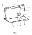
Figure 1 shows, in perspective view, a detector according to an embodiment of the invention, in a first, closed configuration, -
Figure 2 shows the detector inFigure 1 in a second, open configuration, -
Figure 3 shows the detector inFigures 1 and 2 in a third, open configuration, -
Figure 4 shows a flowchart of the power saving feature, and -
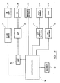
Figure 5 is a schematic circuit diagram of the internal components of the detector ofFigures 1-3 . - Turning to
Figures 1-3 of the drawings, there is shown generally at 10 a hand held electronic detector for detecting the presence/absence and/or nature of a mark on an article (not shown) such as a security mark. The article may comprise a product, such as for example a pack of cigarettes. - The
detector 10 comprises a case orbody 12 of strong, rigid plastics material. Thecase 12 comprises front andrear parts parts Figure 1 ) and a fully open configuration, in which the front and rear parts are angularly spaced by approximately 180°, (shown inFigure 2 ). There is a further defined intermediate open configuration in which the front andrear parts Figure 3 ). When opening the case from the closed position the hinges 18 'lock' when the front and rear parts reach this intermediate position. The hinges will only 'unlock', so that the case can be opened further or closed, if sufficient force is applied. Relative movement of thecase parts Figure 2 is limited byhinges 18. - In an open configuration the
detector 10 presents an article-locating station comprising amounting surface 20 for receiving an article, and alignment means 22, located on themounting surface 20, which in this case is a marked line on themounting surface 20 with which the security mark should be aligned. - An emission/
detection window 26 is provided on thecase part 12b through which radiation can be emitted and received. Thewindow 26 is recessed to protect the surface thereof. Further provided oncase part 12b is aproximity detector 24 for detecting the presence of an object located on themounting surface 20. In this case aninfrared proximity detector 24 is used. - In the open configuration, the
detector 10 is arranged to receive and position an article to be checked, such that a predetermined portion of the article is facing, and accurately aligned with, the emission/detection window 26 and a portion of the article is covering theinfrared proximity detector 24. - On an upper edge of the
rear case part 12b there is located anelectronic display panel 14, comprising an LCD display together withindictor LEDs 16. - Concealed within
case part 12b is electronic circuitry including a programmable controller described below in relation toFigure 5 . Movement from the closed to the open or intermediate configurations is advantageously arranged to turn the electronic circuitry withinpart 12b into an ON state. On turning the circuitry from the OFF state into the ON state an internal check is automatically performed to ensure the circuitry is functioning correctly. If any malfunction or low battery state is detected then this is displayed as a message on thedisplay panel 14. - The electronic controller (not shown) may be programmed for the detection of a specific mark, such as a taggant or other ink exhibiting certain characteristic behaviour under exposure to a certain radiation.
- In the detector's ON state a taggant detection operation constantly occurs. The result of this detection operation is displayed on the
LCD display 14. As an additional indicator, the plurality of LEDs, which are preferably coloured according to their function, illuminate appropriately in accordance with a state (1) no taggant is detected, a state (2) in which a taggant is detected, but it is not the specific one which had been sought, and a state (3) in which the test is deemed positive in that the specific taggant sought is detected. If the controller is appropriately programmed, thedisplay panel 14 may display information related to the detected taggant. - In order to save power a further SLEEP state exists,
Figure 4 illustrates this power saving feature. In the SLEEP state the taggant detection operation does not take place and aproximity detector 24 is turned on. The SLEEP state is entered into if within the previous 30 seconds the detector has not gone through the sequence of (a) detecting a taggant, (b) not detecting a taggant and (c) detecting a taggant. This ensures that if a series of taggant marked objects are tested in quick succession then the detector stays on. The ON state is re-entered, from the SLEEP state, when the proximity detector senses an object being placed onto the mountingsurface 20. - When not in use, the
case parts windows surface 20. The closure of the device also switches OFF the circuitry incase part 12b. Whereas moulded plastic has been used for the case in this embodiment other suitable materials may be used, such as pressed aluminium. -
Figure 5 shows schematically the components within thecase 12. Amicrocontroller 30, deriving power from abattery 32, controls the operation of aninfrared LED 34 viaLED servo 36. Theinfrared LED 34 in use irradiates an article (not shown) with infrared radiation. Infrared radiation which is then emitted from the article by virtue of the presence of a taggant substance on the article is detected byinfrared detector 38 and its signal is then amplified byamplifier 40 and converted by analogue todigital converter 42 before being fed to themicrocontroller 30. - As described above,
proximity detector 24 sends an "article present" or "article not present" signal to themicrocontroller 30. - The
LCD display 14 is driven by anLCD display driver 44 andLEDs 16 are driven by anLED driver 46 under the control of themicrocontroller 30, as described above. - In an alternative embodiment (not shown) the device includes a port which can be used for connecting apparatus or instruments to the device in order to perform tests, in order to reprogram the
microcontroller 30, or in order to couple the device to a secondary, remote detection apparatus. - In a still further embodiment (not shown) the device can be used to automatically actuate another device, for example to activate apparatus or an instrument, or else to operate a lock, in the event that the device detects the presence of an appropriate taggant material.
Claims (12)
- A detector (10) for detecting the presence, absence and/or nature of a security mark on an article,
the detector comprising:a body (12) which has first and second case parts (12a, 12b) movable relative to each other between at least a first, closed configuration, and a second, open configuration;emitting means for emitting radiation provided on the second case part (12b);detection means for detecting radiation provided on the second case part (12b);electronic circuitry provided within the second case part (12b);an article-locating portion (20) for locating an article in use which article-locating portion comprises alignment means (22) for ensuring than an article is aligned with the emitting means and/or the detection means; andwherein in the open configuration the article-locating portion (20) is exposed and the detector is arranged to receive an article to be irradiated; andwherein moving the case parts (12a, 12b) to the closed configuration switches off the electronic circuitry within the second case part (12b). - A detector according to Claim 1, wherein the article-locating portion (20) comprises a mounting surface, against which an article may rest in use, together with alignment means for ensuring that an article is aligned with the emitting means and/or the detection means.
- A detector according to Claim 2, wherein the article-locating portion (20) is arranged to locate an article in use on the mounting surface such that a predetermined portion of the article is presented to the emitting means and/or to the detection means.
- A detector according to any of Claims 1 to 3, wherein the emitting means and detection means are concealed behind at least one window (26).
- A detector according to Claim 2, wherein the alignment means (22) comprises a mark or profile on the mounting surface such that in use the mark or edge provides a reference for the accurate positioning of the article with respect to the emitting means and/or detection means.
- A detector according to any of Claims 1 to 5, wherein the body (12) is provided with proximity detection means (24) for detecting the presence and/or absence of an article.
- A detector according to any of Claims 1 to 6, wherein the body (12) is provided with a display means (14) arranged in use to display the result of a detection operation.
- A detector according to Claim 7, wherein the display means (14) is arranged to provide an indication of the presence/absence and/or nature of a mark detected on an article in use.
- A detector according to any of Claims 1-8, wherein the first and second case parts (12a, 12b) of the body (12) are hingedly connected and hingedly move between the first and second configurations.
- A detector according to any of claims 1-9, wherein at least one movement-stop means is provided to limit the extent of relative movement of the first and second case parts (12a, 12b) of the body.
- A detector according to any of Claims 1-10, wherein means for retaining the first and second case parts (12a, 12b) in an intermediate open configuration are provided.
- A method of detecting the presence, absence and/or nature of a security mark on an article using a detector comprising: a body (12) which has first and second case parts (12a, 12b) movable relative to each other between at least a first, closed configuration, and a second, open configuration; emitting means for emitting radiation provided on the second case part (12b); detection means for detecting radiation provided on the second case part (12b); and electronic circuitry provided within the second case part (12b);, the method comprising:moving the first and second case parts (12a, 12b) from a closed configuration to an open configuration to expose an article-locating portion comprising alignment means;placing an article adjacent to the article-locating portion (20);aligning the article using the alignment means (22);automatically initiating an emission/detection operation;displaying the result of the operation on display means (14) to establish the presence, absence and/or nature of a security mark on the article; andmoving the case parts (12a, 12b) to the closed configuration causing the electronic circuitry within the second case part (12b) to be switched off.
Priority Applications (1)
| Application Number | Priority Date | Filing Date | Title |
|---|---|---|---|
| PL06820553T PL1969567T3 (en) | 2005-12-16 | 2006-12-18 | Detector |
Applications Claiming Priority (2)
| Application Number | Priority Date | Filing Date | Title |
|---|---|---|---|
| GBGB0525664.9A GB0525664D0 (en) | 2005-12-16 | 2005-12-16 | Detector |
| PCT/GB2006/004718 WO2007068952A1 (en) | 2005-12-16 | 2006-12-18 | Detector |
Publications (3)
| Publication Number | Publication Date |
|---|---|
| EP1969567A1 EP1969567A1 (en) | 2008-09-17 |
| EP1969567B1 true EP1969567B1 (en) | 2014-04-09 |
| EP1969567B8 EP1969567B8 (en) | 2014-05-21 |
Family
ID=35736285
Family Applications (1)
| Application Number | Title | Priority Date | Filing Date |
|---|---|---|---|
| EP06820553.3A Not-in-force EP1969567B8 (en) | 2005-12-16 | 2006-12-18 | Detector |
Country Status (13)
| Country | Link |
|---|---|
| US (1) | US8025231B2 (en) |
| EP (1) | EP1969567B8 (en) |
| JP (1) | JP5431731B2 (en) |
| CN (1) | CN201322953Y (en) |
| CA (1) | CA2633220C (en) |
| GB (2) | GB0525664D0 (en) |
| IL (1) | IL192226A (en) |
| MX (1) | MX2008007852A (en) |
| PL (1) | PL1969567T3 (en) |
| PT (1) | PT1969567E (en) |
| RU (1) | RU2435223C2 (en) |
| WO (1) | WO2007068952A1 (en) |
| ZA (1) | ZA200805570B (en) |
Families Citing this family (4)
| Publication number | Priority date | Publication date | Assignee | Title |
|---|---|---|---|---|
| US8487272B2 (en) | 2010-12-14 | 2013-07-16 | Authentix, Inc. | Fluorescence emissions detector |
| GEP201706782B (en) * | 2013-10-11 | 2017-11-27 | Sicpa Holding Sa | Hand-held device and method for authenticating a marking |
| HUE071643T2 (en) | 2013-12-03 | 2025-09-28 | Philip Morris Products Sa | Aerosol-generating article and electrically operated system incorporating a taggant |
| WO2016148867A2 (en) | 2015-03-13 | 2016-09-22 | 3M Innovative Properties Company | Light detection system and method of using same |
Family Cites Families (20)
| Publication number | Priority date | Publication date | Assignee | Title |
|---|---|---|---|---|
| SU548398A1 (en) * | 1975-02-10 | 1977-02-28 | Всесоюзный Проектно-Конструкторский Технологический Институт Атомного Машиностроения И Котлостроения | The method of orientation of the welding tool relative to the product during the welding process |
| SU870323A1 (en) * | 1979-12-26 | 1981-10-07 | Всесоюзный Научно-Исследовательский Институт Полиграфического Машиностроения | Device for side registration of sheets |
| NL8202920A (en) * | 1982-07-20 | 1984-02-16 | Tno | APPARATUS FOR RECOGNIZING AND EXAMINING LEAF ARTICLES SUCH AS BANKNOTES OR THE LIKE. |
| GB2146823B (en) * | 1983-09-07 | 1986-11-26 | Lawrence James Wells | Detecting water marks or the like in paper documents |
| US4742340A (en) * | 1986-12-04 | 1988-05-03 | Isomed, Inc. | Method and apparatus for detecting counterfeit articles |
| SE8903399L (en) * | 1989-10-16 | 1991-04-17 | Sune Eckerstrand | FORM EXAMINER |
| JPH082765Y2 (en) * | 1990-06-15 | 1996-01-29 | 狭山精密工業株式会社 | Locking mechanism of open / close support shaft in bill validator |
| GB2264481B (en) * | 1992-02-26 | 1996-06-19 | Samsonite Corp | Luggage case |
| WO1994016412A1 (en) * | 1993-01-09 | 1994-07-21 | Mars, Incorporated | Detection of counterfeit objects |
| CA2179994A1 (en) * | 1994-01-04 | 1995-07-13 | John Geoffrey Hopwood | Detection of counterfeits objects, for instance counterfeits banknotes |
| GB2309778B (en) * | 1996-02-05 | 2000-05-24 | Mars Inc | Security document validation |
| US5655643A (en) * | 1996-05-08 | 1997-08-12 | United Parcel Service Of America, Inc. | High speed, compound, belted diverter and method of operating same |
| EA003308B1 (en) * | 1999-02-04 | 2003-04-24 | Общество с ограниченной ответственностью Фирма "Дата-Центр" | Method for determining the authenticity, the value and the decay level of banknotes and sorting and counting device |
| JP2001325639A (en) * | 2000-05-15 | 2001-11-22 | Technos Create Co Ltd | Simplified paper money identifier |
| ES2169707A1 (en) * | 2000-12-29 | 2002-07-01 | Investronica Sa | System for recognizing and validating banknotes |
| DE20118645U1 (en) * | 2001-11-15 | 2002-01-17 | Yu, Hung-Ming, Xin-Zhuang, Taipeh | Bill acceptor with a front flap |
| DE10316954A1 (en) * | 2003-04-12 | 2004-10-28 | Abdelkhalic Rbayti | Testing electronics for checking the authenticity of banknotes comprise an LED UV light source and testing and evaluation electronics integrated within a wallet, briefcase or similar |
| JP4566543B2 (en) * | 2003-10-10 | 2010-10-20 | 日本金銭機械株式会社 | Valuable paper sheet identification device |
| JP4237034B2 (en) * | 2003-11-21 | 2009-03-11 | グローリー株式会社 | Image reading device and automatic contract acceptance machine |
| WO2005086099A1 (en) * | 2004-03-08 | 2005-09-15 | Council Of Scientific & Industrial Research | Improved fake currency detector using integrated transmission and reflective spectral response |
-
2005
- 2005-12-16 GB GBGB0525664.9A patent/GB0525664D0/en not_active Ceased
-
2006
- 2006-12-18 JP JP2008545099A patent/JP5431731B2/en not_active Expired - Fee Related
- 2006-12-18 CA CA2633220A patent/CA2633220C/en not_active Expired - Fee Related
- 2006-12-18 EP EP06820553.3A patent/EP1969567B8/en not_active Not-in-force
- 2006-12-18 RU RU2008129066/08A patent/RU2435223C2/en not_active IP Right Cessation
- 2006-12-18 US US12/097,458 patent/US8025231B2/en not_active Expired - Fee Related
- 2006-12-18 MX MX2008007852A patent/MX2008007852A/en active IP Right Grant
- 2006-12-18 PT PT68205533T patent/PT1969567E/en unknown
- 2006-12-18 CN CNU2006900000922U patent/CN201322953Y/en not_active Expired - Fee Related
- 2006-12-18 WO PCT/GB2006/004718 patent/WO2007068952A1/en not_active Ceased
- 2006-12-18 PL PL06820553T patent/PL1969567T3/en unknown
- 2006-12-18 GB GB0625195A patent/GB2433590B/en active Active
-
2008
- 2008-06-16 IL IL192226A patent/IL192226A/en not_active IP Right Cessation
- 2008-06-25 ZA ZA200805570A patent/ZA200805570B/en unknown
Also Published As
| Publication number | Publication date |
|---|---|
| US8025231B2 (en) | 2011-09-27 |
| IL192226A (en) | 2012-12-31 |
| GB0525664D0 (en) | 2006-01-25 |
| GB2433590B (en) | 2008-11-12 |
| CA2633220C (en) | 2013-04-02 |
| GB2433590A (en) | 2007-06-27 |
| EP1969567A1 (en) | 2008-09-17 |
| CN201322953Y (en) | 2009-10-07 |
| MX2008007852A (en) | 2008-11-12 |
| ZA200805570B (en) | 2009-05-27 |
| WO2007068952A1 (en) | 2007-06-21 |
| CA2633220A1 (en) | 2007-06-21 |
| IL192226A0 (en) | 2008-12-29 |
| EP1969567B8 (en) | 2014-05-21 |
| RU2008129066A (en) | 2010-01-27 |
| PT1969567E (en) | 2014-07-17 |
| RU2435223C2 (en) | 2011-11-27 |
| JP5431731B2 (en) | 2014-03-05 |
| US20090255990A1 (en) | 2009-10-15 |
| JP2009519458A (en) | 2009-05-14 |
| PL1969567T3 (en) | 2014-09-30 |
| GB0625195D0 (en) | 2007-01-24 |
Similar Documents
| Publication | Publication Date | Title |
|---|---|---|
| US5918960A (en) | Detection of counterfeit objects, for instance counterfeit banknotes | |
| US5915518A (en) | Detection of counterfeit objects, for instance counterfeit banknotes | |
| EP0679279B1 (en) | Detection of counterfeit objects | |
| IL192225A (en) | Detection apparatus and method | |
| US7715613B2 (en) | UV counterfeit currency detector | |
| EP0891608B1 (en) | Security document validation | |
| US20190304231A1 (en) | Method for authenticating a security marking utilizing long afterglow emission, and security marking comprising one or more afterglow compound | |
| US20020131618A1 (en) | Apparatus and method for detecting the authenticity of secured documents | |
| CN105913545B (en) | Phosphorescence detection device, phosphorescence detection method and paper processing device | |
| IL192226A (en) | Detector for detecting the presence/absence and/or nature of a security mark on an article | |
| US20070145293A1 (en) | Secure tag validation | |
| RU2007108864A (en) | METHOD AND DEVICE FOR MEASURING PROPERTIES OF SHEET MATERIAL | |
| WO2002095693A1 (en) | Counterfeit money sensor machine | |
| RU2115169C1 (en) | Method for bank note genuineness verification | |
| RU158936U1 (en) | DEVICE FOR AUTOMATIC CHECK OF AVAILABILITY ON BANKNOTES OF PROTECTIVE ANTI-STOX TAGS (SPECIAL ELEMENT AND) | |
| RU185984U1 (en) | PORTABLE DEVICE FOR SEMI-AUTOMATIC CHECK OF AVAILABILITY ON THE BANKNOTS OF PROTECTIVE ANTI-STOX TAGS (SPECIAL ELEMENT) | |
| US20060071468A1 (en) | Method and apparatus for verifying the authenticity of bank notes | |
| GB2291705A (en) | Detection of counterfeit bank notes |
Legal Events
| Date | Code | Title | Description |
|---|---|---|---|
| PUAI | Public reference made under article 153(3) epc to a published international application that has entered the european phase |
Free format text: ORIGINAL CODE: 0009012 |
|
| 17P | Request for examination filed |
Effective date: 20080714 |
|
| AK | Designated contracting states |
Kind code of ref document: A1 Designated state(s): AT BE BG CH CY CZ DE DK EE ES FI FR GB GR HU IE IS IT LI LT LU LV MC NL PL PT RO SE SI SK TR |
|
| 17Q | First examination report despatched |
Effective date: 20080912 |
|
| RAP1 | Party data changed (applicant data changed or rights of an application transferred) |
Owner name: FILTRONA C & SP LIMITED |
|
| DAX | Request for extension of the european patent (deleted) | ||
| GRAP | Despatch of communication of intention to grant a patent |
Free format text: ORIGINAL CODE: EPIDOSNIGR1 |
|
| INTG | Intention to grant announced |
Effective date: 20131108 |
|
| GRAS | Grant fee paid |
Free format text: ORIGINAL CODE: EPIDOSNIGR3 |
|
| GRAA | (expected) grant |
Free format text: ORIGINAL CODE: 0009210 |
|
| AK | Designated contracting states |
Kind code of ref document: B1 Designated state(s): AT BE BG CH CY CZ DE DK EE ES FI FR GB GR HU IE IS IT LI LT LU LV MC NL PL PT RO SE SI SK TR |
|
| REG | Reference to a national code |
Ref country code: GB Ref legal event code: FG4D |
|
| REG | Reference to a national code |
Ref country code: AT Ref legal event code: REF Ref document number: 661709 Country of ref document: AT Kind code of ref document: T Effective date: 20140415 Ref country code: CH Ref legal event code: EP |
|
| RBV | Designated contracting states (corrected) |
Designated state(s): AT BE BG CH CY CZ DE DK EE ES FI FR GR HU IE IS IT LI LT LU LV MC NL PL PT RO SE SI SK TR |
|
| REG | Reference to a national code |
Ref country code: IE Ref legal event code: FG4D |
|
| REG | Reference to a national code |
Ref country code: DE Ref legal event code: R096 Ref document number: 602006041033 Country of ref document: DE Effective date: 20140522 |
|
| REG | Reference to a national code |
Ref country code: NL Ref legal event code: T3 |
|
| REG | Reference to a national code |
Ref country code: CH Ref legal event code: NV Representative=s name: DR. LUSUARDI AG, CH |
|
| REG | Reference to a national code |
Ref country code: PT Ref legal event code: SC4A Free format text: AVAILABILITY OF NATIONAL TRANSLATION Effective date: 20140707 |
|
| REG | Reference to a national code |
Ref country code: AT Ref legal event code: MK05 Ref document number: 661709 Country of ref document: AT Kind code of ref document: T Effective date: 20140409 |
|
| REG | Reference to a national code |
Ref country code: PL Ref legal event code: T3 |
|
| PG25 | Lapsed in a contracting state [announced via postgrant information from national office to epo] |
Ref country code: BG Free format text: LAPSE BECAUSE OF FAILURE TO SUBMIT A TRANSLATION OF THE DESCRIPTION OR TO PAY THE FEE WITHIN THE PRESCRIBED TIME-LIMIT Effective date: 20140709 Ref country code: GR Free format text: LAPSE BECAUSE OF FAILURE TO SUBMIT A TRANSLATION OF THE DESCRIPTION OR TO PAY THE FEE WITHIN THE PRESCRIBED TIME-LIMIT Effective date: 20140710 Ref country code: FI Free format text: LAPSE BECAUSE OF FAILURE TO SUBMIT A TRANSLATION OF THE DESCRIPTION OR TO PAY THE FEE WITHIN THE PRESCRIBED TIME-LIMIT Effective date: 20140409 Ref country code: IS Free format text: LAPSE BECAUSE OF FAILURE TO SUBMIT A TRANSLATION OF THE DESCRIPTION OR TO PAY THE FEE WITHIN THE PRESCRIBED TIME-LIMIT Effective date: 20140809 |
|
| PG25 | Lapsed in a contracting state [announced via postgrant information from national office to epo] |
Ref country code: LV Free format text: LAPSE BECAUSE OF FAILURE TO SUBMIT A TRANSLATION OF THE DESCRIPTION OR TO PAY THE FEE WITHIN THE PRESCRIBED TIME-LIMIT Effective date: 20140409 Ref country code: ES Free format text: LAPSE BECAUSE OF FAILURE TO SUBMIT A TRANSLATION OF THE DESCRIPTION OR TO PAY THE FEE WITHIN THE PRESCRIBED TIME-LIMIT Effective date: 20140409 Ref country code: SE Free format text: LAPSE BECAUSE OF FAILURE TO SUBMIT A TRANSLATION OF THE DESCRIPTION OR TO PAY THE FEE WITHIN THE PRESCRIBED TIME-LIMIT Effective date: 20140409 Ref country code: AT Free format text: LAPSE BECAUSE OF FAILURE TO SUBMIT A TRANSLATION OF THE DESCRIPTION OR TO PAY THE FEE WITHIN THE PRESCRIBED TIME-LIMIT Effective date: 20140409 |
|
| REG | Reference to a national code |
Ref country code: DE Ref legal event code: R097 Ref document number: 602006041033 Country of ref document: DE |
|
| PG25 | Lapsed in a contracting state [announced via postgrant information from national office to epo] |
Ref country code: BE Free format text: LAPSE BECAUSE OF FAILURE TO SUBMIT A TRANSLATION OF THE DESCRIPTION OR TO PAY THE FEE WITHIN THE PRESCRIBED TIME-LIMIT Effective date: 20140409 Ref country code: EE Free format text: LAPSE BECAUSE OF FAILURE TO SUBMIT A TRANSLATION OF THE DESCRIPTION OR TO PAY THE FEE WITHIN THE PRESCRIBED TIME-LIMIT Effective date: 20140409 Ref country code: DK Free format text: LAPSE BECAUSE OF FAILURE TO SUBMIT A TRANSLATION OF THE DESCRIPTION OR TO PAY THE FEE WITHIN THE PRESCRIBED TIME-LIMIT Effective date: 20140409 Ref country code: SK Free format text: LAPSE BECAUSE OF FAILURE TO SUBMIT A TRANSLATION OF THE DESCRIPTION OR TO PAY THE FEE WITHIN THE PRESCRIBED TIME-LIMIT Effective date: 20140409 Ref country code: RO Free format text: LAPSE BECAUSE OF FAILURE TO SUBMIT A TRANSLATION OF THE DESCRIPTION OR TO PAY THE FEE WITHIN THE PRESCRIBED TIME-LIMIT Effective date: 20140409 |
|
| PGFP | Annual fee paid to national office [announced via postgrant information from national office to epo] |
Ref country code: CZ Payment date: 20141217 Year of fee payment: 9 Ref country code: IE Payment date: 20141222 Year of fee payment: 9 Ref country code: LT Payment date: 20141218 Year of fee payment: 9 |
|
| PLBE | No opposition filed within time limit |
Free format text: ORIGINAL CODE: 0009261 |
|
| STAA | Information on the status of an ep patent application or granted ep patent |
Free format text: STATUS: NO OPPOSITION FILED WITHIN TIME LIMIT |
|
| PGFP | Annual fee paid to national office [announced via postgrant information from national office to epo] |
Ref country code: NL Payment date: 20141226 Year of fee payment: 9 Ref country code: PL Payment date: 20141217 Year of fee payment: 9 Ref country code: PT Payment date: 20141216 Year of fee payment: 9 |
|
| 26N | No opposition filed |
Effective date: 20150112 |
|
| PG25 | Lapsed in a contracting state [announced via postgrant information from national office to epo] |
Ref country code: IT Free format text: LAPSE BECAUSE OF FAILURE TO SUBMIT A TRANSLATION OF THE DESCRIPTION OR TO PAY THE FEE WITHIN THE PRESCRIBED TIME-LIMIT Effective date: 20140409 |
|
| REG | Reference to a national code |
Ref country code: DE Ref legal event code: R097 Ref document number: 602006041033 Country of ref document: DE Effective date: 20150112 |
|
| PGFP | Annual fee paid to national office [announced via postgrant information from national office to epo] |
Ref country code: DE Payment date: 20150107 Year of fee payment: 9 Ref country code: CH Payment date: 20150108 Year of fee payment: 9 |
|
| PG25 | Lapsed in a contracting state [announced via postgrant information from national office to epo] |
Ref country code: LU Free format text: LAPSE BECAUSE OF FAILURE TO SUBMIT A TRANSLATION OF THE DESCRIPTION OR TO PAY THE FEE WITHIN THE PRESCRIBED TIME-LIMIT Effective date: 20141218 Ref country code: SI Free format text: LAPSE BECAUSE OF FAILURE TO SUBMIT A TRANSLATION OF THE DESCRIPTION OR TO PAY THE FEE WITHIN THE PRESCRIBED TIME-LIMIT Effective date: 20140409 |
|
| REG | Reference to a national code |
Ref country code: FR Ref legal event code: ST Effective date: 20150831 |
|
| PG25 | Lapsed in a contracting state [announced via postgrant information from national office to epo] |
Ref country code: FR Free format text: LAPSE BECAUSE OF NON-PAYMENT OF DUE FEES Effective date: 20141231 |
|
| PG25 | Lapsed in a contracting state [announced via postgrant information from national office to epo] |
Ref country code: MC Free format text: LAPSE BECAUSE OF FAILURE TO SUBMIT A TRANSLATION OF THE DESCRIPTION OR TO PAY THE FEE WITHIN THE PRESCRIBED TIME-LIMIT Effective date: 20140409 |
|
| REG | Reference to a national code |
Ref country code: PT Ref legal event code: MM4A Free format text: LAPSE DUE TO NON-PAYMENT OF FEES Effective date: 20160620 |
|
| PG25 | Lapsed in a contracting state [announced via postgrant information from national office to epo] |
Ref country code: CY Free format text: LAPSE BECAUSE OF FAILURE TO SUBMIT A TRANSLATION OF THE DESCRIPTION OR TO PAY THE FEE WITHIN THE PRESCRIBED TIME-LIMIT Effective date: 20140409 |
|
| REG | Reference to a national code |
Ref country code: DE Ref legal event code: R119 Ref document number: 602006041033 Country of ref document: DE |
|
| REG | Reference to a national code |
Ref country code: LT Ref legal event code: MM4D Effective date: 20151218 |
|
| PG25 | Lapsed in a contracting state [announced via postgrant information from national office to epo] |
Ref country code: HU Free format text: LAPSE BECAUSE OF FAILURE TO SUBMIT A TRANSLATION OF THE DESCRIPTION OR TO PAY THE FEE WITHIN THE PRESCRIBED TIME-LIMIT; INVALID AB INITIO Effective date: 20061218 Ref country code: CZ Free format text: LAPSE BECAUSE OF NON-PAYMENT OF DUE FEES Effective date: 20151218 |
|
| REG | Reference to a national code |
Ref country code: CH Ref legal event code: PL |
|
| PG25 | Lapsed in a contracting state [announced via postgrant information from national office to epo] |
Ref country code: LT Free format text: LAPSE BECAUSE OF NON-PAYMENT OF DUE FEES Effective date: 20151218 Ref country code: PT Free format text: LAPSE BECAUSE OF NON-PAYMENT OF DUE FEES Effective date: 20160620 |
|
| REG | Reference to a national code |
Ref country code: NL Ref legal event code: MM Effective date: 20160101 |
|
| REG | Reference to a national code |
Ref country code: IE Ref legal event code: MM4A |
|
| PG25 | Lapsed in a contracting state [announced via postgrant information from national office to epo] |
Ref country code: NL Free format text: LAPSE BECAUSE OF NON-PAYMENT OF DUE FEES Effective date: 20160101 Ref country code: IE Free format text: LAPSE BECAUSE OF NON-PAYMENT OF DUE FEES Effective date: 20151218 Ref country code: CH Free format text: LAPSE BECAUSE OF NON-PAYMENT OF DUE FEES Effective date: 20151231 Ref country code: DE Free format text: LAPSE BECAUSE OF NON-PAYMENT OF DUE FEES Effective date: 20160701 Ref country code: LI Free format text: LAPSE BECAUSE OF NON-PAYMENT OF DUE FEES Effective date: 20151231 |
|
| PGFP | Annual fee paid to national office [announced via postgrant information from national office to epo] |
Ref country code: TR Payment date: 20141218 Year of fee payment: 9 |
|
| PG25 | Lapsed in a contracting state [announced via postgrant information from national office to epo] |
Ref country code: PL Free format text: LAPSE BECAUSE OF NON-PAYMENT OF DUE FEES Effective date: 20151218 |
|
| PG25 | Lapsed in a contracting state [announced via postgrant information from national office to epo] |
Ref country code: TR Free format text: LAPSE BECAUSE OF NON-PAYMENT OF DUE FEES Effective date: 20151218 |