EP1969365B1 - Electrochemical sensor system using a substrate with at least one aperture and method of making the same - Google Patents
Electrochemical sensor system using a substrate with at least one aperture and method of making the same Download PDFInfo
- Publication number
- EP1969365B1 EP1969365B1 EP06848951.7A EP06848951A EP1969365B1 EP 1969365 B1 EP1969365 B1 EP 1969365B1 EP 06848951 A EP06848951 A EP 06848951A EP 1969365 B1 EP1969365 B1 EP 1969365B1
- Authority
- EP
- European Patent Office
- Prior art keywords
- substrate
- conductive material
- electrode
- hydrogel
- electrochemical sensor
- Prior art date
- Legal status (The legal status is an assumption and is not a legal conclusion. Google has not performed a legal analysis and makes no representation as to the accuracy of the status listed.)
- Active
Links
- 239000000758 substrate Substances 0.000 title claims description 154
- 238000004519 manufacturing process Methods 0.000 title description 4
- 239000004020 conductor Substances 0.000 claims description 106
- 239000000017 hydrogel Substances 0.000 claims description 82
- 239000012491 analyte Substances 0.000 claims description 52
- 239000000463 material Substances 0.000 claims description 29
- 238000000034 method Methods 0.000 claims description 29
- 239000012530 fluid Substances 0.000 claims description 22
- 239000008103 glucose Substances 0.000 claims description 18
- WQZGKKKJIJFFOK-GASJEMHNSA-N Glucose Natural products OC[C@H]1OC(O)[C@H](O)[C@@H](O)[C@@H]1O WQZGKKKJIJFFOK-GASJEMHNSA-N 0.000 claims description 17
- 108090000790 Enzymes Proteins 0.000 claims description 7
- 102000004190 Enzymes Human genes 0.000 claims description 7
- 238000004544 sputter deposition Methods 0.000 claims description 5
- 229920006037 cross link polymer Polymers 0.000 claims description 2
- 239000011343 solid material Substances 0.000 claims 2
- 125000002791 glucosyl group Chemical group C1([C@H](O)[C@@H](O)[C@H](O)[C@H](O1)CO)* 0.000 claims 1
- 210000003491 skin Anatomy 0.000 description 20
- 239000007788 liquid Substances 0.000 description 18
- 238000004458 analytical method Methods 0.000 description 16
- BASFCYQUMIYNBI-UHFFFAOYSA-N platinum Chemical compound [Pt] BASFCYQUMIYNBI-UHFFFAOYSA-N 0.000 description 10
- 230000002829 reductive effect Effects 0.000 description 8
- 238000000576 coating method Methods 0.000 description 7
- 238000012360 testing method Methods 0.000 description 7
- 239000011248 coating agent Substances 0.000 description 6
- 238000003869 coulometry Methods 0.000 description 6
- 229940088598 enzyme Drugs 0.000 description 6
- 210000003722 extracellular fluid Anatomy 0.000 description 6
- 239000002904 solvent Substances 0.000 description 6
- XLYOFNOQVPJJNP-UHFFFAOYSA-N water Substances O XLYOFNOQVPJJNP-UHFFFAOYSA-N 0.000 description 6
- 238000013459 approach Methods 0.000 description 5
- 230000005684 electric field Effects 0.000 description 5
- 230000002452 interceptive effect Effects 0.000 description 5
- 239000007769 metal material Substances 0.000 description 5
- 239000000203 mixture Substances 0.000 description 5
- 229910052697 platinum Inorganic materials 0.000 description 5
- BPYKTIZUTYGOLE-IFADSCNNSA-N Bilirubin Chemical compound N1C(=O)C(C)=C(C=C)\C1=C\C1=C(C)C(CCC(O)=O)=C(CC2=C(C(C)=C(\C=C/3C(=C(C=C)C(=O)N\3)C)N2)CCC(O)=O)N1 BPYKTIZUTYGOLE-IFADSCNNSA-N 0.000 description 4
- PXHVJJICTQNCMI-UHFFFAOYSA-N Nickel Chemical compound [Ni] PXHVJJICTQNCMI-UHFFFAOYSA-N 0.000 description 4
- KDLHZDBZIXYQEI-UHFFFAOYSA-N Palladium Chemical compound [Pd] KDLHZDBZIXYQEI-UHFFFAOYSA-N 0.000 description 4
- HVYWMOMLDIMFJA-DPAQBDIFSA-N cholesterol Chemical compound C1C=C2C[C@@H](O)CC[C@]2(C)[C@@H]2[C@@H]1[C@@H]1CC[C@H]([C@H](C)CCCC(C)C)[C@@]1(C)CC2 HVYWMOMLDIMFJA-DPAQBDIFSA-N 0.000 description 4
- 230000000694 effects Effects 0.000 description 4
- 229910052751 metal Inorganic materials 0.000 description 4
- 239000002184 metal Substances 0.000 description 4
- OKTJSMMVPCPJKN-UHFFFAOYSA-N Carbon Chemical compound [C] OKTJSMMVPCPJKN-UHFFFAOYSA-N 0.000 description 3
- 108010015776 Glucose oxidase Proteins 0.000 description 3
- 210000004369 blood Anatomy 0.000 description 3
- 239000008280 blood Substances 0.000 description 3
- 229910052799 carbon Inorganic materials 0.000 description 3
- 239000003153 chemical reaction reagent Substances 0.000 description 3
- 210000004207 dermis Anatomy 0.000 description 3
- 210000002615 epidermis Anatomy 0.000 description 3
- 239000000499 gel Substances 0.000 description 3
- 230000000887 hydrating effect Effects 0.000 description 3
- 239000000976 ink Substances 0.000 description 3
- -1 polyethylenes Polymers 0.000 description 3
- RYGMFSIKBFXOCR-UHFFFAOYSA-N Copper Chemical compound [Cu] RYGMFSIKBFXOCR-UHFFFAOYSA-N 0.000 description 2
- 239000004366 Glucose oxidase Substances 0.000 description 2
- JVTAAEKCZFNVCJ-UHFFFAOYSA-M Lactate Chemical compound CC(O)C([O-])=O JVTAAEKCZFNVCJ-UHFFFAOYSA-M 0.000 description 2
- 239000004698 Polyethylene Substances 0.000 description 2
- DSVGQVZAZSZEEX-UHFFFAOYSA-N [C].[Pt] Chemical compound [C].[Pt] DSVGQVZAZSZEEX-UHFFFAOYSA-N 0.000 description 2
- 239000000654 additive Substances 0.000 description 2
- 210000001124 body fluid Anatomy 0.000 description 2
- 239000010839 body fluid Substances 0.000 description 2
- 238000006243 chemical reaction Methods 0.000 description 2
- 235000012000 cholesterol Nutrition 0.000 description 2
- 229910052802 copper Inorganic materials 0.000 description 2
- 239000010949 copper Substances 0.000 description 2
- 229940116332 glucose oxidase Drugs 0.000 description 2
- 235000019420 glucose oxidase Nutrition 0.000 description 2
- PCHJSUWPFVWCPO-UHFFFAOYSA-N gold Chemical compound [Au] PCHJSUWPFVWCPO-UHFFFAOYSA-N 0.000 description 2
- 229910052737 gold Inorganic materials 0.000 description 2
- 239000010931 gold Substances 0.000 description 2
- NOESYZHRGYRDHS-UHFFFAOYSA-N insulin Chemical compound N1C(=O)C(NC(=O)C(CCC(N)=O)NC(=O)C(CCC(O)=O)NC(=O)C(C(C)C)NC(=O)C(NC(=O)CN)C(C)CC)CSSCC(C(NC(CO)C(=O)NC(CC(C)C)C(=O)NC(CC=2C=CC(O)=CC=2)C(=O)NC(CCC(N)=O)C(=O)NC(CC(C)C)C(=O)NC(CCC(O)=O)C(=O)NC(CC(N)=O)C(=O)NC(CC=2C=CC(O)=CC=2)C(=O)NC(CSSCC(NC(=O)C(C(C)C)NC(=O)C(CC(C)C)NC(=O)C(CC=2C=CC(O)=CC=2)NC(=O)C(CC(C)C)NC(=O)C(C)NC(=O)C(CCC(O)=O)NC(=O)C(C(C)C)NC(=O)C(CC(C)C)NC(=O)C(CC=2NC=NC=2)NC(=O)C(CO)NC(=O)CNC2=O)C(=O)NCC(=O)NC(CCC(O)=O)C(=O)NC(CCCNC(N)=N)C(=O)NCC(=O)NC(CC=3C=CC=CC=3)C(=O)NC(CC=3C=CC=CC=3)C(=O)NC(CC=3C=CC(O)=CC=3)C(=O)NC(C(C)O)C(=O)N3C(CCC3)C(=O)NC(CCCCN)C(=O)NC(C)C(O)=O)C(=O)NC(CC(N)=O)C(O)=O)=O)NC(=O)C(C(C)CC)NC(=O)C(CO)NC(=O)C(C(C)O)NC(=O)C1CSSCC2NC(=O)C(CC(C)C)NC(=O)C(NC(=O)C(CCC(N)=O)NC(=O)C(CC(N)=O)NC(=O)C(NC(=O)C(N)CC=1C=CC=CC=1)C(C)C)CC1=CN=CN1 NOESYZHRGYRDHS-UHFFFAOYSA-N 0.000 description 2
- 230000000670 limiting effect Effects 0.000 description 2
- 239000011159 matrix material Substances 0.000 description 2
- 239000000178 monomer Substances 0.000 description 2
- 229910052759 nickel Inorganic materials 0.000 description 2
- 229910052763 palladium Inorganic materials 0.000 description 2
- 229920000573 polyethylene Polymers 0.000 description 2
- 239000011148 porous material Substances 0.000 description 2
- 238000012545 processing Methods 0.000 description 2
- 229910052703 rhodium Inorganic materials 0.000 description 2
- 239000010948 rhodium Substances 0.000 description 2
- MHOVAHRLVXNVSD-UHFFFAOYSA-N rhodium atom Chemical compound [Rh] MHOVAHRLVXNVSD-UHFFFAOYSA-N 0.000 description 2
- 239000007787 solid Substances 0.000 description 2
- 208000035874 Excoriation Diseases 0.000 description 1
- 229930091371 Fructose Natural products 0.000 description 1
- RFSUNEUAIZKAJO-ARQDHWQXSA-N Fructose Chemical compound OC[C@H]1O[C@](O)(CO)[C@@H](O)[C@@H]1O RFSUNEUAIZKAJO-ARQDHWQXSA-N 0.000 description 1
- 239000005715 Fructose Substances 0.000 description 1
- 108010050375 Glucose 1-Dehydrogenase Proteins 0.000 description 1
- 102000004877 Insulin Human genes 0.000 description 1
- 108090001061 Insulin Proteins 0.000 description 1
- 239000004743 Polypropylene Substances 0.000 description 1
- 241001313871 Puma Species 0.000 description 1
- 230000005856 abnormality Effects 0.000 description 1
- 230000000996 additive effect Effects 0.000 description 1
- 238000003556 assay Methods 0.000 description 1
- WQZGKKKJIJFFOK-VFUOTHLCSA-N beta-D-glucose Chemical compound OC[C@H]1O[C@@H](O)[C@H](O)[C@@H](O)[C@@H]1O WQZGKKKJIJFFOK-VFUOTHLCSA-N 0.000 description 1
- 239000001913 cellulose Substances 0.000 description 1
- 229920002678 cellulose Polymers 0.000 description 1
- 239000000919 ceramic Substances 0.000 description 1
- 229910010293 ceramic material Inorganic materials 0.000 description 1
- 150000001875 compounds Chemical class 0.000 description 1
- 239000012084 conversion product Substances 0.000 description 1
- 238000004132 cross linking Methods 0.000 description 1
- 238000013461 design Methods 0.000 description 1
- 206010012601 diabetes mellitus Diseases 0.000 description 1
- 235000005911 diet Nutrition 0.000 description 1
- 230000037213 diet Effects 0.000 description 1
- 238000009792 diffusion process Methods 0.000 description 1
- 238000009826 distribution Methods 0.000 description 1
- 229940079593 drug Drugs 0.000 description 1
- 239000003814 drug Substances 0.000 description 1
- 239000003792 electrolyte Substances 0.000 description 1
- 238000009713 electroplating Methods 0.000 description 1
- 238000006911 enzymatic reaction Methods 0.000 description 1
- 210000000416 exudates and transudate Anatomy 0.000 description 1
- 230000003116 impacting effect Effects 0.000 description 1
- 230000002401 inhibitory effect Effects 0.000 description 1
- 229940125396 insulin Drugs 0.000 description 1
- 230000010354 integration Effects 0.000 description 1
- 230000003834 intracellular effect Effects 0.000 description 1
- 210000002977 intracellular fluid Anatomy 0.000 description 1
- 150000002632 lipids Chemical class 0.000 description 1
- 238000012423 maintenance Methods 0.000 description 1
- 150000002739 metals Chemical class 0.000 description 1
- 229910000510 noble metal Inorganic materials 0.000 description 1
- 206010033675 panniculitis Diseases 0.000 description 1
- 239000002245 particle Substances 0.000 description 1
- 150000002978 peroxides Chemical class 0.000 description 1
- 210000002381 plasma Anatomy 0.000 description 1
- 239000004417 polycarbonate Substances 0.000 description 1
- 229920000515 polycarbonate Polymers 0.000 description 1
- 229920000570 polyether Polymers 0.000 description 1
- 229920001155 polypropylene Polymers 0.000 description 1
- 239000000843 powder Substances 0.000 description 1
- 238000002360 preparation method Methods 0.000 description 1
- 230000035945 sensitivity Effects 0.000 description 1
- 210000002966 serum Anatomy 0.000 description 1
- 210000004304 subcutaneous tissue Anatomy 0.000 description 1
- 150000003626 triacylglycerols Chemical class 0.000 description 1
Images


Classifications
-
- C—CHEMISTRY; METALLURGY
- C12—BIOCHEMISTRY; BEER; SPIRITS; WINE; VINEGAR; MICROBIOLOGY; ENZYMOLOGY; MUTATION OR GENETIC ENGINEERING
- C12Q—MEASURING OR TESTING PROCESSES INVOLVING ENZYMES, NUCLEIC ACIDS OR MICROORGANISMS; COMPOSITIONS OR TEST PAPERS THEREFOR; PROCESSES OF PREPARING SUCH COMPOSITIONS; CONDITION-RESPONSIVE CONTROL IN MICROBIOLOGICAL OR ENZYMOLOGICAL PROCESSES
- C12Q1/00—Measuring or testing processes involving enzymes, nucleic acids or microorganisms; Compositions therefor; Processes of preparing such compositions
- C12Q1/001—Enzyme electrodes
- C12Q1/005—Enzyme electrodes involving specific analytes or enzymes
- C12Q1/006—Enzyme electrodes involving specific analytes or enzymes for glucose
-
- A—HUMAN NECESSITIES
- A61—MEDICAL OR VETERINARY SCIENCE; HYGIENE
- A61B—DIAGNOSIS; SURGERY; IDENTIFICATION
- A61B5/00—Measuring for diagnostic purposes; Identification of persons
- A61B5/145—Measuring characteristics of blood in vivo, e.g. gas concentration, pH value; Measuring characteristics of body fluids or tissues, e.g. interstitial fluid, cerebral tissue
- A61B5/1468—Measuring characteristics of blood in vivo, e.g. gas concentration, pH value; Measuring characteristics of body fluids or tissues, e.g. interstitial fluid, cerebral tissue using chemical or electrochemical methods, e.g. by polarographic means
- A61B5/1477—Measuring characteristics of blood in vivo, e.g. gas concentration, pH value; Measuring characteristics of body fluids or tissues, e.g. interstitial fluid, cerebral tissue using chemical or electrochemical methods, e.g. by polarographic means non-invasive
-
- A—HUMAN NECESSITIES
- A61—MEDICAL OR VETERINARY SCIENCE; HYGIENE
- A61B—DIAGNOSIS; SURGERY; IDENTIFICATION
- A61B5/00—Measuring for diagnostic purposes; Identification of persons
- A61B5/145—Measuring characteristics of blood in vivo, e.g. gas concentration, pH value; Measuring characteristics of body fluids or tissues, e.g. interstitial fluid, cerebral tissue
- A61B5/14507—Measuring characteristics of blood in vivo, e.g. gas concentration, pH value; Measuring characteristics of body fluids or tissues, e.g. interstitial fluid, cerebral tissue specially adapted for measuring characteristics of body fluids other than blood
-
- A—HUMAN NECESSITIES
- A61—MEDICAL OR VETERINARY SCIENCE; HYGIENE
- A61B—DIAGNOSIS; SURGERY; IDENTIFICATION
- A61B5/00—Measuring for diagnostic purposes; Identification of persons
- A61B5/145—Measuring characteristics of blood in vivo, e.g. gas concentration, pH value; Measuring characteristics of body fluids or tissues, e.g. interstitial fluid, cerebral tissue
- A61B5/14532—Measuring characteristics of blood in vivo, e.g. gas concentration, pH value; Measuring characteristics of body fluids or tissues, e.g. interstitial fluid, cerebral tissue for measuring glucose, e.g. by tissue impedance measurement
-
- A—HUMAN NECESSITIES
- A61—MEDICAL OR VETERINARY SCIENCE; HYGIENE
- A61B—DIAGNOSIS; SURGERY; IDENTIFICATION
- A61B5/00—Measuring for diagnostic purposes; Identification of persons
- A61B5/145—Measuring characteristics of blood in vivo, e.g. gas concentration, pH value; Measuring characteristics of body fluids or tissues, e.g. interstitial fluid, cerebral tissue
- A61B5/14546—Measuring characteristics of blood in vivo, e.g. gas concentration, pH value; Measuring characteristics of body fluids or tissues, e.g. interstitial fluid, cerebral tissue for measuring analytes not otherwise provided for, e.g. ions, cytochromes
-
- A—HUMAN NECESSITIES
- A61—MEDICAL OR VETERINARY SCIENCE; HYGIENE
- A61B—DIAGNOSIS; SURGERY; IDENTIFICATION
- A61B5/00—Measuring for diagnostic purposes; Identification of persons
- A61B5/145—Measuring characteristics of blood in vivo, e.g. gas concentration, pH value; Measuring characteristics of body fluids or tissues, e.g. interstitial fluid, cerebral tissue
- A61B5/1468—Measuring characteristics of blood in vivo, e.g. gas concentration, pH value; Measuring characteristics of body fluids or tissues, e.g. interstitial fluid, cerebral tissue using chemical or electrochemical methods, e.g. by polarographic means
-
- Y—GENERAL TAGGING OF NEW TECHNOLOGICAL DEVELOPMENTS; GENERAL TAGGING OF CROSS-SECTIONAL TECHNOLOGIES SPANNING OVER SEVERAL SECTIONS OF THE IPC; TECHNICAL SUBJECTS COVERED BY FORMER USPC CROSS-REFERENCE ART COLLECTIONS [XRACs] AND DIGESTS
- Y10—TECHNICAL SUBJECTS COVERED BY FORMER USPC
- Y10T—TECHNICAL SUBJECTS COVERED BY FORMER US CLASSIFICATION
- Y10T29/00—Metal working
- Y10T29/49—Method of mechanical manufacture
- Y10T29/49002—Electrical device making
- Y10T29/49117—Conductor or circuit manufacturing
- Y10T29/49124—On flat or curved insulated base, e.g., printed circuit, etc.
Definitions
- the present invention generally relates to an electrochemical sensor system and method of making the same. More specifically, the present invention relates to an electrochemical sensor system using a substrate that has porosity therethrough and a method of making of the same.
- a test sensor contains biosensing or reagent material that reacts with blood glucose.
- the testing end of the sensor is adapted to be placed into the fluid being tested, for example, blood that has accumulated on a person's finger after the finger has been pricked.
- the fluid is drawn into a capillary channel that extends in the sensor from the testing end to the reagent material by capillary action so that a sufficient amount of fluid to be tested is drawn into the sensor.
- the fluid then chemically reacts with the reagent material in the sensor resulting in an electrical signal indicative of the glucose level in the fluid being tested. This signal is supplied to the meter via contact areas located near the rear or contact end of the sensor and becomes the measured output.
- One existing process for forming an electrochemical sensor is to deposit a conductive metal onto a substrate and then use a subtractive method for removing selected portions of the deposited conductive metal.
- Another existing process is to print the electrode by using a conductive ink, which is an additive process.
- the conductive ink may contain platinized carbon, platinum or other noble metal with a carrier that includes carbon particles.
- the area of the conductive metal that can be used as an electrode is limited to a single two-dimensional footprint. Since the conductive material is expensive, it is desirable for the manufacturer to use as little conductive material as necessary while still maintaining the desired functionality.
- an electrochemical sensor system is adapted to assist in determining an analyte concentration of a fluid.
- the electrochemical sensor system comprises a substrate, conductive material and a hydrogel.
- the substrate has porosity therethrough.
- the conductive material includes at least one electrode.
- the at least one electrode is coupled to the substrate.
- the at least one electrode has a first surface and an opposing second surface.
- the hydrogel is adapted to assist in carrying the analyte of the fluid to the first and second surfaces of the at least one electrode.
- an electrochemical sensor system is formed that is adapted to assist in determining an analyte concentration.
- a substrate having porosity therethrough is provided.
- Conductive material is added to the substrate.
- the conductive material has a first side and a second side.
- the conductive material forms at least one electrode.
- a hydrogel is provided. The substrate and the at least one added electrode is contacted by the hydrogel such that the analyte is adapted to contact the first side and the second side of the at least one electrode.
- an analyte concentration of a fluid is determined.
- An electrochemical sensor system includes a substrate, conductive material, and a hydrogel.
- the substrate has porosity therethrough.
- the conductive material is coupled to the substrate.
- the conductive material has a first side and a second side.
- the conductive material forms at least one electrode.
- the substrate and the at least one added electrode contact the hydrogel such that the analyte is adapted to contact the first side and the second side of the at least one electrode.
- the electrochemical sensor system is placed on the skin. The analyte concentration of the fluid is determined.
- the present invention is directed to an electrochemical sensor system and a process of making the same that reduces the quantity of conductive material that is used to form the at least one electrode.
- the quantity of conductive material may be reduced.
- the size of the electrochemical sensor system may also be reduced.
- the cost of making the electrochemical sensor is also reduced.
- the electrochemical sensor system is adapted to be used with an instrument or meter to determine the concentration of an analyte.
- the present invention is desirably used in a transdermal analyte system because of the cost of the conductive material. Additionally, in transdermal analyte systems, the ability to reduce the relatively large size of a working electrode is advantageous. The relatively large size of the working electrode is needed in transdermal analyte systems to give a measurable signal at the very low analyte concentrations. These very low analyte concentrations may be extracted from, for example, the interstitial fluid via a hydrogel or liquid.
- the electrochemical sensor system assists in determining concentrations of analytes.
- Analytes that may be measured include glucose, lipid profiles (e.g., cholesterol, triglycerides, LDL and HDL), microalbumin, fructose, lactate, or bilirubin. It is contemplated that other analyte concentrations may be determined.
- the analytes may be in, for example, intracellular and/or intercellular fluid. Intercellular fluids include ISF (interstitial fluid), a blood plasma sample, a blood serum sample, and exudate.
- ISF interstitial fluid
- concentration refers to an analyte concentration, activity (e.g., enzymes and electrolytes), titers (e.g., antibodies), or any other measure concentration used to measure the desired analyte.
- the electrochemical sensor system may include an appropriately selected enzyme to react with the desired analyte or analytes to be tested.
- an enzyme that may be used to react with glucose is glucose oxidase. It is contemplated that other enzymes may be used to react with glucose such as glucose dehydrogenase.
- the electrochemical sensor system is adapted to assist in determining an analyte concentration and comprises a substrate, conductive material and a hydrogel or liquid.
- the conductive material is used to form the at least one electrode.
- the hydrogel assists in carrying the analyte to the conductive material.
- FIG. 1 depicts a continuous sheet of an electrochemical sensor 10 that includes a continuous substrate 12 with a plurality of discrete conductive material areas 14 that has been added to the continuous substrate 12.
- the continuous substrate 12 depicted in FIG. 1 is a scrim, screen, woven material or a combination thereof.
- the continuous sheet of the electrochemical sensor may then be cut to provide for individual electrochemical sensors.
- the electrochemical sensor system 100 includes a substrate 112, conductive material 114, and a hydrogel 116.
- the conductive material 114 is coupled to the substrate 112. More specifically, as shown in FIG. 2b , the conductive material 114 is attached to the substrate 112.
- the hydrogel 116 as viewed in FIG. 2b , is located both above and below the conductive material 114 and the substrate 112.
- the substrate 112 to be used in the electrochemical sensor system 100 is porous and includes sufficient strength to support the conductive material 114.
- the substrate may comprise a screen, scrim, woven material, or combinations thereof. It is contemplated that the substrate may be of other forms that are sufficient porous so as to allow the hydrogel or liquid to move therethrough and contact both sides 114a, 114b of the conductive material 114.
- a solid, non-porous material may have at least one and more desirably a plurality of apertures formed therein that allows both sides of the conductive material to be accessible to the hydrogel or liquid.
- the substrate 112 forms a plurality of apertures 126 (see FIG. 2a ) therein.
- the apertures may be of various sizes and shapes, but are formed to allow the hydrogel or fluid to contact the conductive material 114 on both sides 114a, 114b.
- the apertures are desirably sized and shaped to correspond with the analyte that is to flow through the apertures 126. This would include the desirable amount and rate of the analyte flow.
- the electrodes may be of a smaller size, which leads to making a smaller electrochemical sensor. It is contemplated, however, that the substrate may form exactly one aperture therethrough that allows the hydrogel or fluid to contact both surfaces of the conductive material.
- the substrate may be made from a variety of materials.
- the substrate may be formed from a polymeric material.
- polymeric materials that may be used in forming the substrate include polyethylenes, polypropylenes, polyethylene terephthlates (PET), polyethers, polycarbonates, or combinations thereof.
- PET polyethylene terephthlates
- the polymeric material may be pre-formed with apertures or the polymeric material may have apertures formed therethrough in later processing.
- the substrate such as cellulose material and porous ceramic. If a solid non-porous material is used, then the material may be porous by pre-forming apertures therethrough. Alternatively, the ceramic material may be formed in a manner that forms apertures therethrough in later processing.
- the substrate may be formed of a metallic material, but this is often undesirable because such a substrate would likely need to include an insulating dielectric layer.
- the substrate may also be used to create an electric field pattern that prevents or inhibits interfering materials from getting to the analysis area. By reducing the interfering materials, the determination of the analyte concentration may be improved.
- the substrate creates a positive or negative charged surface that assists in preventing or inhibiting interfering materials from getting to the analysis area. In the case of determining the analyte concentration of glucose, such a field would have little or no effect with glucose because glucose does not have a charge. It is very desirable for the electric field pattern to have little or no effect on the analyte concentration that is being determined.
- Such electric field patterns may be applied to the substrate (e.g., lower portion of the substrate closest to the skin) that prevent or inhibit interfering compounds from coming through based on charged properties.
- the analysis typically occurs on an opposing surface of the substrate (e.g., upper portion of the substrate that is furthest away from the skin).
- the electric field patterns in one embodiment may be located in apertures formed in the substrate.
- the electric field patterns may be applied to the substrate by, for example, printing or coating methods.
- exactly one side of the substrate is printed or coated with binding materials that would bind interfering materials. It is contemplated that both sides of the substrate may include such binding materials.
- the substrate may include an enzyme that is used to assist in determining the analyte concentration.
- the enzyme may be coated on one side of the substrate, while the conductive material is located on an opposing side.
- the intermediate in the analysis process would be produced in close proximity to where the next step of the analysis process occurs. This increases the conversion efficiency and, thus, increases the signal observed at the sensor.
- the analyte to be determined is glucose using the enzyme glucose oxidase
- peroxide would form at the substrate surface with the glucose oxidase coating.
- the coating is desirable for the coating to cover the substrate in such a manner that the substrate remains porous. For example, if the substrate is a scrim or a screen, the coating is added so as to leave the plurality of apertures formed in the scrim or screen partially open so as to assist the hydrogel or fluid in contacting both sides of the conductive material.
- the substrate may include a mediator that is an electron acceptor and assists in generating a current that corresponds to the analyte concentration. It is also contemplated that other additives may be added to the substrate to assist in facilitating the determination of the selected analyte.
- the conductive material 114 is added to the substrate 112 and forms at least one electrode.
- the conductive material 114 forms a plurality of electrodes.
- the conductive material 114 forms a plurality of electrodes, which includes a working electrode 118 and a counter electrode 120.
- the working electrode 118 and a counter electrode 120 create an electrochemical current that can flow when these electrodes are electrically connected and a potential is created between them.
- the plurality of electrode may include three or more electrodes such as a counter electrode, a working electrode, and a reference electrode.
- An example of an electrochemical sensor system that includes three electrodes is depicted in FIG. 3 . Specifically, an electrochemical sensor system 200 of FIG.
- the conductive material 214 includes a working electrode 218, a counter electrode 220 and a reference electrode 222. It is contemplated that more or less electrodes can be formed using the conductive material.
- the electrons created by the enzymatic reaction flow through the working electrode to a meter or instrument that measures the magnitude of the current flow.
- the counter electrode provides a fixed potential against which the working electrode is controlled.
- the counter electrode may also be used to complete the electrical circuit.
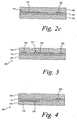
- the conductive material may be added on a surface of the substrate in one embodiment. It is contemplated that the added conductive material, if printed for example, may be added on a surface of the substrate and also penetrate the surface of the substrate. Examples of the conductive material being added on a surface of a substrate are shown in FIGs. 2c, 3 and 4 .
- an electrochemical sensor 300 is shown that includes the substrate 112, conductive material 314, and a hydrogel 316.
- the conductive material 314 includes a working electrode 318 and a counter electrode 320 in which the working and counter electrodes 318, 320 are located on opposing sides of the substrate 112.
- the conductive material may be located at least partially within the substrate.
- an electrochemical sensor 400 is shown that includes the substrate 112, conductive material 414 and a hydrogel 416.
- the conductive material 414 is located at least partially within the substrate 112. More specifically, the conductive material 114, which includes a working electrode 418 and a counter electrode 420, is located within the substrate 112.
- the conductive material may be located both on the substrate and within the substrate.
- an electrochemical sensor system 500 is shown that includes the substrate 112, conductive material 514 and a hydrogel 516.
- the conductive material 514 includes a working electrode 518 and a counter electrode 520.
- the working electrode 518 is located within the substrate 112 and the counter electrode 520 is located on the substrate 112.
- an electrochemical sensor system 600 of FIG. 7 includes the substrate 112, conductive material 614 and hydrogel 616.
- the conductive material 614 includes a working electrode 618 and a counter electrode 620 and a reference electrode 622.
- the working and reference electrodes 618, 622 are located within the substrate 112 and the counter electrode 620 is located on substrate 112.
- the conductive material may be a metallic material or other conductive material such as platinum carbon.
- conductive metallic materials include copper, nickel, gold, platinum, palladium, rhodium or combinations thereof.
- the thickness of the conductive metallic material is generally from about 10 to about 10,000 Angstroms. The thickness of the conductive metallic material is more typically from about 100 to about 1,000 Angstroms.
- the thickness of the conductive material may be greater than the thickness of the substrate.
- the thickness of the conductive material is platinum carbon, then the thickness of such a conductive material is typically greater than the thickness of the substrate. It is also contemplated that the thickness of the conductive material may be less than the thickness of the substrate. For example, if a platinum coating is added to the substrate, then the thickness of such a coating is typically less than the thickness of the substrate.
- the size and shape of the conductive material is shown in FIG. 2a as including a generally circular portion 114c and an extension portion 114d extending therefrom.
- the size and shape of the conductive material can vary from that shown in FIGs. 1, 2a .
- the size and shape of the conductive material is selected to facilitate the determination of the analyte concentration as well as reduce the cost associated with manufacturing the same.
- the size and shape of the conductive material may also be selected for other reasons. For example, if a reservoir is used to replenish the hydrogel, then the placement of the conductive material may be optimized to provide the desired porosity to carry the hydrogel from the reservoir to a skin-contacting location.
- a reservoir may be used if the characteristics of the hydrogel are prone to changing over the testing period, which typically includes the solvent percentage of the hydrogel being reduced over time.
- a hydrogel is used to assist in hydrating the skin and carrying the analyte of interest to the at least one electrode formed by the conductive material.
- the content of the solvent (e.g., water) in the hydrogel can vary.
- the hydrogel 116 is supported by the substrate 112 with the conductive material 114. Thus, the need for an additional substrate material is eliminated.
- a hydrogel composition is defined herein as including a cross-linked polymer gel.
- the hydrogel composition generally comprises at least one monomer and a solvent.
- the solvent is typically substantially biocompatible with the skin.
- Non-limiting examples of solvents that may be used in the hydrogel composition include water and a water mixture.
- the amount of solvent in the hydrogel is generally from about 10 to about 95 weight percent and may vary depending on the monomer amount, crosslinking, and/or the desired composition of the gel.
- the amount of hydrogel that is selected is based on the need to provide a hydrated skin and having the hydrogel remain in intimate contact with the skin.
- One disadvantage of using a large amount of hydrogel in the electrochemical sensor system is the potential impact on the lag time of the analyte getting to the at least one electrode and, thus, the potential impact on the analysis time.
- the hydrogel capable of contacting both sides of at least one electrode, the effect of impacting the lag times of the analyte getting to the electrodes is reduced.
- the hydrogel capable of contacting both sides of a plurality of electrodes By having an electrochemical sensor system that is able to contact both sides of at least one electrode and desirably a plurality of electrodes, the present invention has the ability to use a greater amount of water in the hydrogel.
- a liquid may be used to assist in hydrating the skin and carrying the analyte of interest to the at least one electrode formed by the conductive material. It is contemplated that the liquid or the hydrogel may be located in a material matrix. In such an embodiment, the material matrix must allow the movement of the liquid or hydrogel to the at least one electrode.
- the mediator may be located in the hydrogel or liquid. To maximize efficiency, the distribution of the mediator may be structured. It is also contemplated that other components may be located within the hydrogel or liquid.
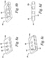
- a single electrode is shown in different embodiments on a portion of the substrate.
- a substrate 650 is shown with a plurality of apertures formed 652 therein.
- the substrate 650 has a single electrode 656 that is located on a surface 650a of the substrate 650.
- a hydrogel or liquid 658 is added over the substrate 650 and electrode 656 as shown in FIGs. 8c and 8d .
- the hydrogel or liquid 658 extends into and through the plurality of apertures 652.
- the electrode 656 does not extend into the plurality of apertures 652. It is contemplated, however, that the electrode may extend into the plurality of apertures.
- a substrate 650 is shown with a plurality of apertures formed 652 therein.
- the substrate 650 has a single electrode 666 that is located on surfaces 650a, 650b of the substrate 650. More specifically, the electrode 666 is located on opposing surfaces 650a, 650b of the substrate 650 and extends through the plurality of apertures 652.
- the electrode 666 substantially fills the plurality of apertures 652. It is contemplated that the electrode may partially fill the plurality of apertures such that an electrical connection is still established therethrough.
- a hydrogel or liquid 668 is added over the substrate and electrode 666 as shown in FIGs. 9c and 9d . It is contemplated that the hydrogel or liquid may extend into and through the plurality of apertures if the electrode 666 does not substantially fill the plurality of apertures 652.
- a substrate 650 is shown with a plurality of apertures formed 652 therein.
- the substrate 650 has a single electrode 676 that includes a first electrode section 676a and a second electrode section 676b.
- the first electrode section 676a is located on surface 650a, while the second electrode section 676b is located on surface 650b of the substrate 650.
- the first and second electrode sections 676a, 676b do not extend through the plurality of apertures 652. It is contemplated that the electrode sections may extend partially into the plurality of apertures.
- a hydrogel or liquid 678 is added over the substrate and electrode sections 676a, 676b as shown in FIGs. 10c and 10d .
- the hydrogel or liquid 680 extends into and through the plurality of apertures 652.
- a single electrode e.g., a working electrode
- the working electrode, counter electrode or any other electrode may be on both sides of the substrate, on only one side of the substrate, or on opposite sides of the substrate.
- an electrochemical sensor system is formed that is adapted to assist in determining an analyte concentration.
- a substrate with a porosity therethrough e.g., substrate 112 in one embodiment comprises a screen, scrim, woven material or combinations thereof. As discussed above, the substrate 112 forms apertures therein.
- Conductive material e.g., conductive material 1114 is added to the substrate.
- the conductive material has a first side and a second side and forms at least one electrode.
- a hydrogel e.g., hydrogel 116) or liquid is provided.
- the substrate with the plurality of electrodes contacts the hydrogel such that the analyte is adapted to contact the first side and the second side of the at least one electrode.
- the conductive material as shown in, for example, FIG. 3 is placed in a general center of the hydrogel.
- the conductive material may be added to the substrate by different techniques.
- the conductive material is added to the substrate by sputtering.
- the sputtering process may deposit metals such as platinum, copper, nickel, gold, palladium, rhodium and combinations thereof. It is contemplated that other conductive materials may be sputtered to the substrate.
- the sputtering process places conductive material on at least one surface of the substrate and the conductive material may penetrate the substrate to some extent. It is contemplated that the sputtering process may be used to place conductive material on both sides of the substrate.
- the conductive material is added to the substrate by printing.
- the printing may be performed by using platinum or platinized carbon inks. It is contemplated that other conductive materials may be printed to the substrate.
- the conductive material is placed on at least one surface and the conductive material may penetrate the substrate to some extent. It is contemplated that the printing process may add conductive material on both sides of the substrate.
- the conductive material may be added to the substrate using electroplating or powder coating.
- all of the electrodes are added to the substrate. It is contemplated that less than all of the electrodes are added to the substrate. For example, one electrode may be added to the substrate while the other electrode is located near the analysis area.
- the present invention may be used in a transdermal approach in which the analyte is continuously monitored.
- the electrochemical system 200 of FIG. 3 is shown in a transdermal application. Specifically, the electrochemical system 200 is shown being placed above a stratum cornium layer 252 of epidermis 250 in FIG. 11 .
- the stratum cornium layer 250 has a plurality of channels 252a-d formed therein. The channels may be of different sizes and depths depending on the analyte being tested and the location of the analyte in the skin.
- the plurality of channels 252a may be formed by different methods such as a laser-initiated opening, a lance, or a pressure member adapted to apply pressure to and stretch the skin in preparation for forming a tear in the skin. It is contemplated that other methods may be used such as using pumas or gels, tape stripping or various skin abrasion methods.
- the analyte of interest may be located in the epidermis 250 or dermis layer 254.
- one analyte e.g., glucose
- Glucose diffuses through the fluid paths that are established in the plurality of channels 252 formed in the stratum cornium layer 250.
- the hydrogel with generally high water content, maintains a fluid channel for diffusion of the analyte of interest.
- the electrochemical sensor system may also be used to continuously monitor analytes in the ISF.
- Such analytes may be located on the skin.
- the analytes are typically located in the transdermal region (epidermis, dermis or subcutaneous tissue) of the skin.
- the analytes are brought to the skin surface using diffusional channels.
- the analysis is then carried out at the surface of the skin using several analytical techniques.
- Electrochemical sensor system 700 of FIG. 12 includes a substrate 712 with conductive material 714, hydrogel 716 and a working electrode 718.
- the electrochemical sensor system 700 is placed on skin 740.
- the conductive material 714 includes a counter electrode 720.
- the working electrode 718 is printed on backing material 730.
- the backing material 730 may be made of a polymeric backing material.
- the coulometric analysis is conducted between the counter electrode 720 on the substrate 712 and the working electrode 718.
- the coulometric analysis is based on the conversion of all of the analyte in a defined volume.
- the defined area of FIG. 12 is the area 732 between the substrate 712/counter electrode 720 and the working electrode 718. This area 732 is predominately occupied by the hydrogel 716, but also contains the diffused analyte (e.g., glucose) or the conversion product of glucose.
- the analysis is based on the integration of the current generated over a time period.
- the side of the substrate that is located away from the skin may also form the lower part of a chamber that contains a liquid such as water that forms a reservoir for the hydrogel that is below the scrim and in contact with the skin. This would assist in hydrating the hydrogel for longer periods of time.
- the location of the sensors on the substrate provides for significant digress of freedom in the design and materials that can be used on the opposing surface of the substrate.
- a highly hydrated thick hydrogel may be used so as to provide a reservoir for the hydrogel in contact with the skin. The increased thickness would have little or no impact on the lag times.
Description
- The present invention generally relates to an electrochemical sensor system and method of making the same. More specifically, the present invention relates to an electrochemical sensor system using a substrate that has porosity therethrough and a method of making of the same.
- The quantitative determination of analytes in body fluids is of great importance in the diagnoses and maintenance of certain physiological abnormalities. For example, lactate, cholesterol and bilirubin should be monitored in certain individuals. In particular, it is important that diabetic individuals frequently check the glucose level in their body fluids to regulate the glucose intake in their diets. The results of such tests can be used to determine what, if any, insulin or other medication needs to be administered. In one type of blood-glucose testing system, sensors are used to test a sample of blood. Such as
US6551496B1 discloses a glucose sensor based upon a microporous architecture. - A test sensor contains biosensing or reagent material that reacts with blood glucose. The testing end of the sensor is adapted to be placed into the fluid being tested, for example, blood that has accumulated on a person's finger after the finger has been pricked. The fluid is drawn into a capillary channel that extends in the sensor from the testing end to the reagent material by capillary action so that a sufficient amount of fluid to be tested is drawn into the sensor. The fluid then chemically reacts with the reagent material in the sensor resulting in an electrical signal indicative of the glucose level in the fluid being tested. This signal is supplied to the meter via contact areas located near the rear or contact end of the sensor and becomes the measured output.
- One existing process for forming an electrochemical sensor is to deposit a conductive metal onto a substrate and then use a subtractive method for removing selected portions of the deposited conductive metal. Another existing process is to print the electrode by using a conductive ink, which is an additive process. The conductive ink may contain platinized carbon, platinum or other noble metal with a carrier that includes carbon particles. In both of these existing processes, the area of the conductive metal that can be used as an electrode is limited to a single two-dimensional footprint. Since the conductive material is expensive, it is desirable for the manufacturer to use as little conductive material as necessary while still maintaining the desired functionality.
- It would be desirable to have an electrochemical sensor system that reduces the amount of conductive material needed, which reduces the cost, while at the same time still maintaining the desired functionality.
- According to claim 1, an electrochemical sensor system is adapted to assist in determining an analyte concentration of a fluid. The electrochemical sensor system comprises a substrate, conductive material and a hydrogel. The substrate has porosity therethrough. The conductive material includes at least one electrode. The at least one electrode is coupled to the substrate. The at least one electrode has a first surface and an opposing second surface. The hydrogel is adapted to assist in carrying the analyte of the fluid to the first and second surfaces of the at least one electrode.
- According to claim 10, an electrochemical sensor system is formed that is adapted to assist in determining an analyte concentration. A substrate having porosity therethrough is provided. Conductive material is added to the substrate. The conductive material has a first side and a second side. The conductive material forms at least one electrode. A hydrogel is provided. The substrate and the at least one added electrode is contacted by the hydrogel such that the analyte is adapted to contact the first side and the second side of the at least one electrode.
- According to claim 15, an analyte concentration of a fluid is determined. An electrochemical sensor system is provided that includes a substrate, conductive material, and a hydrogel. The substrate has porosity therethrough. The conductive material is coupled to the substrate. The conductive material has a first side and a second side. The conductive material forms at least one electrode. The substrate and the at least one added electrode contact the hydrogel such that the analyte is adapted to contact the first side and the second side of the at least one electrode. The electrochemical sensor system is placed on the skin. The analyte concentration of the fluid is determined.
-
-
FIG. 1 is a continuous sheet of an electrochemical sensor that includes a continuous substrate with conductive material according to one embodiment; -
FIG. 2a is a top perspective view of an electrochemical sensor with a hydrogel according to one embodiment. -
FIG. 2b shows an enlarged side view of an electrochemical sensor with a hydrogel ofFIG. 2a . -
FIG. 2c is an enlarged cross-sectional view taken generally alongline 2c-2c ofFIG. 2a . -
FIG. 3 is a cross-sectional view of an electrochemical sensor system with three electrodes according to one embodiment. -
FIG. 4 is a cross-sectional view of an electrochemical sensor system with two electrodes according to one embodiment. -
FIG. 5 is a cross-sectional view of an electrochemical sensor system with two electrodes according to another embodiment. -
FIG. 6 is a cross-sectional view of an electrochemical sensor system with two electrodes according to a further embodiment. -
FIG. 7 is a cross-sectional view of an electrochemical sensor system with three electrodes according to a further embodiment. -
FIG. 8a is a top perspective view of a portion of a substrate according to one embodiment. -
FIG. 8b is a top perspective view of the substrate ofFIG. 8a with an electrode added to one side according to one embodiment. -
FIG. 8c is a top perspective view ofFIG. 8b with a hydrogel or fluid added according to one embodiment. -
FIG. 8d is a side view ofFIG. 8c . -
FIG. 9a is a top perspective view of a portion of a substrate according to one embodiment. -
FIG. 9b is a top perspective view of the substrate ofFIG. 9a with an electrode added to both sides according to one embodiment. -
FIG. 9c is a top perspective view ofFIG. 9b with a hydrogel or fluid added according to one embodiment. -
FIG. 9d is a side view ofFIG. 9c . -
FIG. 10a is a top perspective view of a portion of a substrate according to one embodiment. -
FIG. 10b is a top perspective view of the substrate ofFIG. 10a with an electrode added to two sides according to another embodiment. -
FIG. 10c is a top perspective view ofFIG. 10b with a hydrogel or fluid being added according to another embodiment. -
FIG. 10d is a side view ofFIG. 10c . -
FIG. 11 is the electrochemical sensor system ofFIG. 3 being placed over a surface of the skin according to one embodiment. -
FIG. 12 is an electrochemical sensor system that is used in a coulometric analysis approach according to one embodiment. - The present invention is directed to an electrochemical sensor system and a process of making the same that reduces the quantity of conductive material that is used to form the at least one electrode. By using both sides of the conductive material forming the at least one electrode, the quantity of conductive material may be reduced. When the quantity of conductive material needed is reduced, the size of the electrochemical sensor system may also be reduced. By reducing the conductive material, the cost of making the electrochemical sensor is also reduced. The electrochemical sensor system is adapted to be used with an instrument or meter to determine the concentration of an analyte.
- The present invention is desirably used in a transdermal analyte system because of the cost of the conductive material. Additionally, in transdermal analyte systems, the ability to reduce the relatively large size of a working electrode is advantageous. The relatively large size of the working electrode is needed in transdermal analyte systems to give a measurable signal at the very low analyte concentrations. These very low analyte concentrations may be extracted from, for example, the interstitial fluid via a hydrogel or liquid.
- The electrochemical sensor system assists in determining concentrations of analytes. Analytes that may be measured include glucose, lipid profiles (e.g., cholesterol, triglycerides, LDL and HDL), microalbumin, fructose, lactate, or bilirubin. It is contemplated that other analyte concentrations may be determined. The analytes may be in, for example, intracellular and/or intercellular fluid. Intercellular fluids include ISF (interstitial fluid), a blood plasma sample, a blood serum sample, and exudate. As used within this application, the term "concentration" refers to an analyte concentration, activity (e.g., enzymes and electrolytes), titers (e.g., antibodies), or any other measure concentration used to measure the desired analyte.
- The electrochemical sensor system may include an appropriately selected enzyme to react with the desired analyte or analytes to be tested. For example, an enzyme that may be used to react with glucose is glucose oxidase. It is contemplated that other enzymes may be used to react with glucose such as glucose dehydrogenase.
- The electrochemical sensor system is adapted to assist in determining an analyte concentration and comprises a substrate, conductive material and a hydrogel or liquid. The conductive material is used to form the at least one electrode. The hydrogel assists in carrying the analyte to the conductive material.
- A non-limiting example of a continuous sheet of an electrochemical sensor is shown in
FIG. 1. FIG. 1 depicts a continuous sheet of an electrochemical sensor 10 that includes acontinuous substrate 12 with a plurality of discrete conductive material areas 14 that has been added to thecontinuous substrate 12. Thecontinuous substrate 12 depicted inFIG. 1 is a scrim, screen, woven material or a combination thereof. The continuous sheet of the electrochemical sensor may then be cut to provide for individual electrochemical sensors. - Referring to
FIGs. 2a-c , a non-limiting example of anelectrochemical sensor system 100 is shown. Theelectrochemical sensor system 100 includes asubstrate 112,conductive material 114, and ahydrogel 116. Theconductive material 114 is coupled to thesubstrate 112. More specifically, as shown inFIG. 2b , theconductive material 114 is attached to thesubstrate 112. Thehydrogel 116, as viewed inFIG. 2b , is located both above and below theconductive material 114 and thesubstrate 112. - The
substrate 112 to be used in theelectrochemical sensor system 100 is porous and includes sufficient strength to support theconductive material 114. The substrate may comprise a screen, scrim, woven material, or combinations thereof. It is contemplated that the substrate may be of other forms that are sufficient porous so as to allow the hydrogel or liquid to move therethrough and contact bothsides conductive material 114. For example, a solid, non-porous material may have at least one and more desirably a plurality of apertures formed therein that allows both sides of the conductive material to be accessible to the hydrogel or liquid. By having both sides of the conductive material accessible to the hydrogel or liquid, the time required for the analyte to reach the conductive material is reduced. - In one embodiment, the
substrate 112 forms a plurality of apertures 126 (seeFIG. 2a ) therein. The apertures may be of various sizes and shapes, but are formed to allow the hydrogel or fluid to contact theconductive material 114 on bothsides apertures 126. This would include the desirable amount and rate of the analyte flow. - By using both
sides conductive material 114, the overall footprint and the amount of conductive material required to form the at least one electrode is reduced. Thus, by allowing the hydrogel to contact both sides of the conductive material, the electrodes may be of a smaller size, which leads to making a smaller electrochemical sensor. It is contemplated, however, that the substrate may form exactly one aperture therethrough that allows the hydrogel or fluid to contact both surfaces of the conductive material. - The substrate may be made from a variety of materials. For example, the substrate may be formed from a polymeric material. Non-limiting examples of polymeric materials that may be used in forming the substrate include polyethylenes, polypropylenes, polyethylene terephthlates (PET), polyethers, polycarbonates, or combinations thereof. The polymeric material may be pre-formed with apertures or the polymeric material may have apertures formed therethrough in later processing.
- It is contemplated that other polymeric materials may be used in forming the substrate such as cellulose material and porous ceramic. If a solid non-porous material is used, then the material may be porous by pre-forming apertures therethrough. Alternatively, the ceramic material may be formed in a manner that forms apertures therethrough in later processing. The substrate may be formed of a metallic material, but this is often undesirable because such a substrate would likely need to include an insulating dielectric layer.
- The substrate may also be used to create an electric field pattern that prevents or inhibits interfering materials from getting to the analysis area. By reducing the interfering materials, the determination of the analyte concentration may be improved. In this embodiment, the substrate creates a positive or negative charged surface that assists in preventing or inhibiting interfering materials from getting to the analysis area. In the case of determining the analyte concentration of glucose, such a field would have little or no effect with glucose because glucose does not have a charge. It is very desirable for the electric field pattern to have little or no effect on the analyte concentration that is being determined.
- Such electric field patterns may be applied to the substrate (e.g., lower portion of the substrate closest to the skin) that prevent or inhibit interfering compounds from coming through based on charged properties. In this embodiment, the analysis typically occurs on an opposing surface of the substrate (e.g., upper portion of the substrate that is furthest away from the skin). The electric field patterns in one embodiment may be located in apertures formed in the substrate.
- The electric field patterns may be applied to the substrate by, for example, printing or coating methods. In one embodiment, exactly one side of the substrate is printed or coated with binding materials that would bind interfering materials. It is contemplated that both sides of the substrate may include such binding materials.
- In another embodiment, the substrate may include an enzyme that is used to assist in determining the analyte concentration. In this embodiment, the enzyme may be coated on one side of the substrate, while the conductive material is located on an opposing side. In this embodiment, the intermediate in the analysis process would be produced in close proximity to where the next step of the analysis process occurs. This increases the conversion efficiency and, thus, increases the signal observed at the sensor. For example, if the analyte to be determined is glucose using the enzyme glucose oxidase, then peroxide would form at the substrate surface with the glucose oxidase coating. It is desirable for the coating to cover the substrate in such a manner that the substrate remains porous. For example, if the substrate is a scrim or a screen, the coating is added so as to leave the plurality of apertures formed in the scrim or screen partially open so as to assist the hydrogel or fluid in contacting both sides of the conductive material.
- It is also contemplated that the substrate may include a mediator that is an electron acceptor and assists in generating a current that corresponds to the analyte concentration. It is also contemplated that other additives may be added to the substrate to assist in facilitating the determination of the selected analyte.
- The
conductive material 114 is added to thesubstrate 112 and forms at least one electrode. Typically, theconductive material 114 forms a plurality of electrodes. For example, inFIG. 2c , theconductive material 114 forms a plurality of electrodes, which includes a workingelectrode 118 and acounter electrode 120. The workingelectrode 118 and acounter electrode 120 create an electrochemical current that can flow when these electrodes are electrically connected and a potential is created between them. The plurality of electrode may include three or more electrodes such as a counter electrode, a working electrode, and a reference electrode. An example of an electrochemical sensor system that includes three electrodes is depicted inFIG. 3 . Specifically, anelectrochemical sensor system 200 ofFIG. 3 includes thesubstrate 112,conductive material 214 and ahydrogel 216. Theconductive material 214 includes a workingelectrode 218, acounter electrode 220 and areference electrode 222. It is contemplated that more or less electrodes can be formed using the conductive material. - The electrons created by the enzymatic reaction flow through the working electrode to a meter or instrument that measures the magnitude of the current flow. The counter electrode provides a fixed potential against which the working electrode is controlled. The counter electrode may also be used to complete the electrical circuit.
- The conductive material may be added on a surface of the substrate in one embodiment. It is contemplated that the added conductive material, if printed for example, may be added on a surface of the substrate and also penetrate the surface of the substrate. Examples of the conductive material being added on a surface of a substrate are shown in
FIGs. 2c, 3 and 4 . InFIG. 4 , anelectrochemical sensor 300 is shown that includes thesubstrate 112,conductive material 314, and ahydrogel 316. Theconductive material 314 includes a workingelectrode 318 and acounter electrode 320 in which the working andcounter electrodes substrate 112. - In another embodiment, the conductive material may be located at least partially within the substrate. Referring to
FIG. 5 , anelectrochemical sensor 400 is shown that includes thesubstrate 112,conductive material 414 and ahydrogel 416. Theconductive material 414 is located at least partially within thesubstrate 112. More specifically, theconductive material 114, which includes a workingelectrode 418 and acounter electrode 420, is located within thesubstrate 112. - It is contemplated that the conductive material may be located both on the substrate and within the substrate. For example, in
FIG. 6 , anelectrochemical sensor system 500 is shown that includes thesubstrate 112,conductive material 514 and ahydrogel 516. Theconductive material 514 includes a workingelectrode 518 and acounter electrode 520. The workingelectrode 518 is located within thesubstrate 112 and thecounter electrode 520 is located on thesubstrate 112. - In another embodiment, an
electrochemical sensor system 600 ofFIG. 7 includes thesubstrate 112,conductive material 614 andhydrogel 616. Theconductive material 614 includes a workingelectrode 618 and acounter electrode 620 and areference electrode 622. The working andreference electrodes substrate 112 and thecounter electrode 620 is located onsubstrate 112. - The conductive material may be a metallic material or other conductive material such as platinum carbon. Non-limiting examples of conductive metallic materials include copper, nickel, gold, platinum, palladium, rhodium or combinations thereof. The thickness of the conductive metallic material is generally from about 10 to about 10,000 Angstroms. The thickness of the conductive metallic material is more typically from about 100 to about 1,000 Angstroms.
- The thickness of the conductive material may be greater than the thickness of the substrate. For example, if the conductive material is platinum carbon, then the thickness of such a conductive material is typically greater than the thickness of the substrate. It is also contemplated that the thickness of the conductive material may be less than the thickness of the substrate. For example, if a platinum coating is added to the substrate, then the thickness of such a coating is typically less than the thickness of the substrate.
- The size and shape of the conductive material is shown in
FIG. 2a as including a generallycircular portion 114c and anextension portion 114d extending therefrom. The size and shape of the conductive material can vary from that shown inFIGs. 1, 2a . The size and shape of the conductive material is selected to facilitate the determination of the analyte concentration as well as reduce the cost associated with manufacturing the same. The size and shape of the conductive material may also be selected for other reasons. For example, if a reservoir is used to replenish the hydrogel, then the placement of the conductive material may be optimized to provide the desired porosity to carry the hydrogel from the reservoir to a skin-contacting location. A reservoir may be used if the characteristics of the hydrogel are prone to changing over the testing period, which typically includes the solvent percentage of the hydrogel being reduced over time. - In one embodiment, a hydrogel is used to assist in hydrating the skin and carrying the analyte of interest to the at least one electrode formed by the conductive material. The content of the solvent (e.g., water) in the hydrogel can vary. To increase the mechanical strength of the
hydrogel 116, thehydrogel 116 is supported by thesubstrate 112 with theconductive material 114. Thus, the need for an additional substrate material is eliminated. - A hydrogel composition is defined herein as including a cross-linked polymer gel. The hydrogel composition generally comprises at least one monomer and a solvent. The solvent is typically substantially biocompatible with the skin. Non-limiting examples of solvents that may be used in the hydrogel composition include water and a water mixture. The amount of solvent in the hydrogel is generally from about 10 to about 95 weight percent and may vary depending on the monomer amount, crosslinking, and/or the desired composition of the gel.
- The amount of hydrogel that is selected is based on the need to provide a hydrated skin and having the hydrogel remain in intimate contact with the skin. One disadvantage of using a large amount of hydrogel in the electrochemical sensor system is the potential impact on the lag time of the analyte getting to the at least one electrode and, thus, the potential impact on the analysis time. By having an electrochemical sensor system in which the hydrogel is capable of contacting both sides of at least one electrode, the effect of impacting the lag times of the analyte getting to the electrodes is reduced. It is advantageous to have the hydrogel capable of contacting both sides of a plurality of electrodes. By having an electrochemical sensor system that is able to contact both sides of at least one electrode and desirably a plurality of electrodes, the present invention has the ability to use a greater amount of water in the hydrogel.
- It is also contemplated that a liquid may be used to assist in hydrating the skin and carrying the analyte of interest to the at least one electrode formed by the conductive material. It is contemplated that the liquid or the hydrogel may be located in a material matrix. In such an embodiment, the material matrix must allow the movement of the liquid or hydrogel to the at least one electrode.
- It is also contemplated that the mediator may be located in the hydrogel or liquid. To maximize efficiency, the distribution of the mediator may be structured. It is also contemplated that other components may be located within the hydrogel or liquid.
- Referring to
FIGs. 8-10 , a single electrode is shown in different embodiments on a portion of the substrate. Referring first toFIGs. 8a-8d , asubstrate 650 is shown with a plurality of apertures formed 652 therein. As shown inFIG. 8b , thesubstrate 650 has asingle electrode 656 that is located on asurface 650a of thesubstrate 650. A hydrogel orliquid 658 is added over thesubstrate 650 andelectrode 656 as shown inFIGs. 8c and 8d . The hydrogel orliquid 658 extends into and through the plurality ofapertures 652. In this embodiment, theelectrode 656 does not extend into the plurality ofapertures 652. It is contemplated, however, that the electrode may extend into the plurality of apertures. - Referring to
FIGs. 9a-9d , asubstrate 650 is shown with a plurality of apertures formed 652 therein. As shown inFIG. 9b , thesubstrate 650 has asingle electrode 666 that is located onsurfaces substrate 650. More specifically, theelectrode 666 is located on opposingsurfaces substrate 650 and extends through the plurality ofapertures 652. Theelectrode 666 substantially fills the plurality ofapertures 652. It is contemplated that the electrode may partially fill the plurality of apertures such that an electrical connection is still established therethrough. A hydrogel orliquid 668 is added over the substrate andelectrode 666 as shown inFIGs. 9c and 9d . It is contemplated that the hydrogel or liquid may extend into and through the plurality of apertures if theelectrode 666 does not substantially fill the plurality ofapertures 652. - Referring to
FIGs. 10a-10d , asubstrate 650 is shown with a plurality of apertures formed 652 therein. As shown inFIG. 10b , thesubstrate 650 has asingle electrode 676 that includes afirst electrode section 676a and asecond electrode section 676b. Thefirst electrode section 676a is located onsurface 650a, while thesecond electrode section 676b is located onsurface 650b of thesubstrate 650. Thus, the first andsecond electrode sections apertures 652. It is contemplated that the electrode sections may extend partially into the plurality of apertures. A hydrogel orliquid 678 is added over the substrate andelectrode sections FIGs. 10c and 10d . The hydrogel or liquid 680 extends into and through the plurality ofapertures 652. - In the embodiments depicted in
FIGs. 8-10 , only a single electrode (e.g., a working electrode) has been depicted. It is contemplated that the working electrode, counter electrode or any other electrode may be on both sides of the substrate, on only one side of the substrate, or on opposite sides of the substrate. - According to one method, an electrochemical sensor system is formed that is adapted to assist in determining an analyte concentration. A substrate with a porosity therethrough (e.g., substrate 112) in one embodiment comprises a screen, scrim, woven material or combinations thereof. As discussed above, the
substrate 112 forms apertures therein. Conductive material (e.g., conductive material 114) is added to the substrate. The conductive material has a first side and a second side and forms at least one electrode. A hydrogel (e.g., hydrogel 116) or liquid is provided. The substrate with the plurality of electrodes contacts the hydrogel such that the analyte is adapted to contact the first side and the second side of the at least one electrode. The conductive material as shown in, for example,FIG. 3 is placed in a general center of the hydrogel. - The conductive material may be added to the substrate by different techniques. In one method, the conductive material is added to the substrate by sputtering. The sputtering process may deposit metals such as platinum, copper, nickel, gold, palladium, rhodium and combinations thereof. It is contemplated that other conductive materials may be sputtered to the substrate. The sputtering process places conductive material on at least one surface of the substrate and the conductive material may penetrate the substrate to some extent. It is contemplated that the sputtering process may be used to place conductive material on both sides of the substrate.
- In another method, the conductive material is added to the substrate by printing. The printing may be performed by using platinum or platinized carbon inks. It is contemplated that other conductive materials may be printed to the substrate. In a typical printing process, the conductive material is placed on at least one surface and the conductive material may penetrate the substrate to some extent. It is contemplated that the printing process may add conductive material on both sides of the substrate.
- It is contemplated that other methods may be used in adding the conductive material to the substrate. For example, the conductive material maybe added to the substrate using electroplating or powder coating.
- In one embodiment, all of the electrodes are added to the substrate. It is contemplated that less than all of the electrodes are added to the substrate. For example, one electrode may be added to the substrate while the other electrode is located near the analysis area.
- The present invention may be used in a transdermal approach in which the analyte is continuously monitored. As shown in
FIG. 11 , theelectrochemical system 200 ofFIG. 3 is shown in a transdermal application. Specifically, theelectrochemical system 200 is shown being placed above astratum cornium layer 252 ofepidermis 250 inFIG. 11 . Thestratum cornium layer 250 has a plurality of channels 252a-d formed therein. The channels may be of different sizes and depths depending on the analyte being tested and the location of the analyte in the skin. - The plurality of channels 252a may be formed by different methods such as a laser-initiated opening, a lance, or a pressure member adapted to apply pressure to and stretch the skin in preparation for forming a tear in the skin. It is contemplated that other methods may be used such as using pumas or gels, tape stripping or various skin abrasion methods. The analyte of interest may be located in the
epidermis 250 ordermis layer 254. For example, one analyte (e.g., glucose) is located in the dermis layer. Glucose, for example, diffuses through the fluid paths that are established in the plurality ofchannels 252 formed in thestratum cornium layer 250. The hydrogel, with generally high water content, maintains a fluid channel for diffusion of the analyte of interest. - The electrochemical sensor system may also be used to continuously monitor analytes in the ISF. Such analytes may be located on the skin. The analytes are typically located in the transdermal region (epidermis, dermis or subcutaneous tissue) of the skin. The analytes are brought to the skin surface using diffusional channels. The analysis is then carried out at the surface of the skin using several analytical techniques.
- It is contemplated that an electrochemical sensor system of the present invention may use a coulometric analysis approach. The coulometric analysis approach would likely increase the sensitivity of the assay in that more signal would be generated. One example of an electrochemical sensor system that uses a coulometric analysis approach is shown in connection with
FIG. 12 .Electrochemical sensor system 700 ofFIG. 12 includes a substrate 712 withconductive material 714,hydrogel 716 and a workingelectrode 718. Theelectrochemical sensor system 700 is placed onskin 740. Theconductive material 714 includes a counter electrode 720. In this embodiment, the workingelectrode 718 is printed onbacking material 730. Thebacking material 730 may be made of a polymeric backing material. The coulometric analysis is conducted between the counter electrode 720 on the substrate 712 and the workingelectrode 718. The coulometric analysis is based on the conversion of all of the analyte in a defined volume. The defined area ofFIG. 12 is thearea 732 between the substrate 712/counter electrode 720 and the workingelectrode 718. Thisarea 732 is predominately occupied by thehydrogel 716, but also contains the diffused analyte (e.g., glucose) or the conversion product of glucose. The analysis is based on the integration of the current generated over a time period. - The side of the substrate that is located away from the skin may also form the lower part of a chamber that contains a liquid such as water that forms a reservoir for the hydrogel that is below the scrim and in contact with the skin. This would assist in hydrating the hydrogel for longer periods of time. The location of the sensors on the substrate provides for significant digress of freedom in the design and materials that can be used on the opposing surface of the substrate. A highly hydrated thick hydrogel may be used so as to provide a reservoir for the hydrogel in contact with the skin. The increased thickness would have little or no impact on the lag times.
Claims (15)
- An electrochemical sensor system (100) for assisting in determining an analyte concentration of a fluid, the electrochemical sensor system comprising:a substrate (112) having porosity therethrough;a conductive material (114) including at least one electrode (118, 120), the at least one electrode being coupled to the substrate, the at least one electrode having a first surface (114a) and a second surface (114b) on the opposite side of the first surface; andcharacterized by comprisinga hydrogel (116) located above and below the conductive material (114) and the substrate (112), the hydrogel (116) contacting the at least one electrode (118, 120) and the substrate, wherein the porosity of the substrate allows the hydrogel to move through the substrate and thereby the hydrogel carries the analyte of the fluid into contact with both the first and second surfaces of the at least one electrode.
- The system of claim 1, wherein the substrate (112) is a screen, scrim, woven material or solid material with apertures.
- The system of claim 1, wherein the at least one electrode (118, 120) is located on a surface of the substrate (112).
- The system of claim 1, wherein a portion of the at least one electrode (414, 418, 420) is located within the substrate (112).
- The system of claim 1, wherein the at least one electrode has a first section and a second section, the first section having the first surface and the second section having the opposing second surface.
- The system of claim 1, wherein the porosity of the substrate (112) includes at least one aperture being formed therethrough, the conductive material substantially filling the at least one aperture.
- The system of claim 1, wherein the hydrogel (116) is in contact with both the first and second surfaces (114a, 114b) of the at least one electrode.
- The system of claim 1, wherein the hydrogel is a cross-linked polymer.
- The system of claim 1, further comprising an enzyme on the substrate.
- A method of forming an electrochemical sensor system for assisting in determining an analyte concentration, the method comprising the acts of:providing a substrate (112) having porosity therethrough;adding conductive material (114) to the substrate (112), the conductive material having a first side (114a) and a second side (114b) on the opposite side of the first side, the conductive material forming at least one electrode (118, 120); andcontacting the substrate and the at least one electrode with a hydrogel (116),characterized by the hydrogel (116) being located above and below the conductive material (114) and the substrate (112), wherein the porosity of the substrate allows the hydrogel to move through the substrate (112) and thereby the hydrogel carries the analyte into contact with both the first side (114a) and the second side (114b) of the at least one electrode (118, 120).
- The method of claim 10, wherein the conductive material (114) is added to the substrate by sputtering.
- The method of claim 10, wherein the conductive material (114) is added to the substrate by printing.
- The method of claim 10, wherein the analyte is glucose.
- The method of claim 10, wherein the substrate (112) is a screen, scrim, woven material or solid material with apertures.
- A method of determining an analyte concentration of a fluid, the method comprising the acts of:providing an electrochemical sensor system (100) including a substrate (112), conductive material (114), and a hydrogel (116), the substrate having porosity therethrough, the conductive material being coupled to the substrate, the conductive material having a first side (114a) and a second side (114b) on the opposite side of the first side, the conductive material forming at least one electrode (118, 120), the substrate and the at least one electrode being contacted with the hydrogel;placing the electrochemical sensor system (100) in contact with the fluid ; anddetermining the analyte concentration of the fluid,characterized in that the hydrogel (116) is located above and below the conductive material (114) and the substrate (112), wherein the porosity of the substrate allows the hydrogel to move through the substrate (112) and thereby the hydrogel carries the analyte into contact with both the first side (114a) and the second side (114b) of the at least one electrode (118, 120).
Applications Claiming Priority (2)
| Application Number | Priority Date | Filing Date | Title |
|---|---|---|---|
| US75414005P | 2005-12-27 | 2005-12-27 | |
| PCT/US2006/049039 WO2007076017A2 (en) | 2005-12-27 | 2006-12-21 | Electrochemical sensor system using a substrate with at least one aperature and method of making the same |
Publications (2)
| Publication Number | Publication Date |
|---|---|
| EP1969365A2 EP1969365A2 (en) | 2008-09-17 |
| EP1969365B1 true EP1969365B1 (en) | 2016-09-21 |
Family
ID=38218668
Family Applications (1)
| Application Number | Title | Priority Date | Filing Date |
|---|---|---|---|
| EP06848951.7A Active EP1969365B1 (en) | 2005-12-27 | 2006-12-21 | Electrochemical sensor system using a substrate with at least one aperture and method of making the same |
Country Status (9)
| Country | Link |
|---|---|
| US (2) | US9668683B2 (en) |
| EP (1) | EP1969365B1 (en) |
| JP (1) | JP5021678B2 (en) |
| CN (1) | CN101454667B (en) |
| BR (1) | BRPI0620735A2 (en) |
| CA (1) | CA2635670C (en) |
| NO (1) | NO20083293L (en) |
| RU (1) | RU2008130870A (en) |
| WO (1) | WO2007076017A2 (en) |
Families Citing this family (11)
| Publication number | Priority date | Publication date | Assignee | Title |
|---|---|---|---|---|
| US9668683B2 (en) * | 2005-12-27 | 2017-06-06 | Ascensia Diabetes Care Holdings Ag | Electrochemical sensor system using a substrate with at least one aperture and method of making the same |
| JP5729651B2 (en) * | 2010-02-23 | 2015-06-03 | ゴードン アトウッド,クリストファー | Biomolecules and methods for detecting their interaction characteristics |
| US10448872B2 (en) | 2010-03-16 | 2019-10-22 | Medtronic Minimed, Inc. | Analyte sensor apparatuses having improved electrode configurations and methods for making and using them |
| JP5661424B2 (en) * | 2010-10-29 | 2015-01-28 | アークレイ株式会社 | Electrochemical sensor |
| WO2012078908A1 (en) * | 2010-12-09 | 2012-06-14 | Abbott Diabetes Care Inc. | Analyte sensors with a sensing surface having small sensing spots |
| US8808532B2 (en) * | 2011-01-20 | 2014-08-19 | Medtronic Minimed, Inc | Electrode compositions for use with analyte sensors |
| JP5834599B2 (en) * | 2011-08-01 | 2015-12-24 | オムロンヘルスケア株式会社 | Sensor head, electrochemical sensor, and method of using electrochemical sensor |
| WO2014164731A1 (en) * | 2013-03-11 | 2014-10-09 | University Of Utah Research Foundation | Sensor systems |
| CN104792845A (en) * | 2014-08-07 | 2015-07-22 | 中国科学院微电子研究所 | Sensing device |
| US9907498B2 (en) * | 2014-09-04 | 2018-03-06 | Verily Life Sciences Llc | Channel formation |
| EP3981330A3 (en) * | 2020-10-12 | 2022-06-29 | Biometrica S.r.l. | Electrochemical physiological sensor |
Citations (1)
| Publication number | Priority date | Publication date | Assignee | Title |
|---|---|---|---|---|
| WO1996000110A1 (en) * | 1994-06-24 | 1996-01-04 | Cygnus, Inc. | Iontophoretic sampling device and method |
Family Cites Families (28)
| Publication number | Priority date | Publication date | Assignee | Title |
|---|---|---|---|---|
| US3912614A (en) * | 1972-01-10 | 1975-10-14 | Int Biophysics Corp | Sensor |
| JPS6125541A (en) * | 1984-07-16 | 1986-02-04 | 株式会社日立製作所 | Subcateneous glucose sensor |
| CN85107234A (en) * | 1985-09-24 | 1987-04-01 | 物理传感器公司 | Use the chemical selection sensor of admittance modulating membrane |
| JPS63135131A (en) * | 1986-11-28 | 1988-06-07 | 株式会社日立製作所 | Percataneous sensor |
| US4874500A (en) * | 1987-07-15 | 1989-10-17 | Sri International | Microelectrochemical sensor and sensor array |
| US5183549A (en) * | 1990-01-26 | 1993-02-02 | Commtech International Management Corporation | Multi-analyte sensing electrolytic cell |
| JPH03251229A (en) * | 1990-02-28 | 1991-11-08 | Nec Corp | Blood sugar value measuring instrument |
| US5161532A (en) * | 1990-04-19 | 1992-11-10 | Teknekron Sensor Development Corporation | Integral interstitial fluid sensor |
| DE4115414C2 (en) * | 1991-05-10 | 1995-07-06 | Meinhard Prof Dr Knoll | Process for the production of miniaturized chemo- and biosensor elements with an ion-selective membrane as well as carriers for these elements |
| DE4137261C2 (en) * | 1991-11-13 | 1995-06-29 | Meinhard Prof Dr Knoll | Miniaturized sensor element for determining substance concentrations in liquids and process for its production |
| US6030827A (en) * | 1998-01-23 | 2000-02-29 | I-Stat Corporation | Microfabricated aperture-based sensor |
| US6134461A (en) * | 1998-03-04 | 2000-10-17 | E. Heller & Company | Electrochemical analyte |
| CA2265119C (en) * | 1998-03-13 | 2002-12-03 | Cygnus, Inc. | Biosensor, iontophoretic sampling system, and methods of use thereof |
| JP3251229B2 (en) | 1998-03-25 | 2002-01-28 | 株式会社山本製作所 | Grain discharge device in a grain tank |
| US6338790B1 (en) * | 1998-10-08 | 2002-01-15 | Therasense, Inc. | Small volume in vitro analyte sensor with diffusible or non-leachable redox mediator |
| JP4227235B2 (en) | 1998-12-24 | 2009-02-18 | キヤノンアネルバ株式会社 | Substrate processing equipment |
| US7045054B1 (en) * | 1999-09-20 | 2006-05-16 | Roche Diagnostics Corporation | Small volume biosensor for continuous analyte monitoring |
| US6551496B1 (en) * | 2000-03-03 | 2003-04-22 | Ysi Incorporated | Microstructured bilateral sensor |
| EP1167538A1 (en) | 2000-06-30 | 2002-01-02 | Schibli Engineering GmbH | Biosensor and method for its production |
| ATE468531T1 (en) | 2001-05-30 | 2010-06-15 | I Sens Inc | BIOSENSOR |
| US7384791B2 (en) * | 2004-01-21 | 2008-06-10 | Hewlett-Packard Development Company, L.P. | Method of analyzing blood |
| ES2548235T3 (en) * | 2004-10-28 | 2015-10-15 | Bayer Healthcare Llc | Hydrogel composition |
| US20060094945A1 (en) * | 2004-10-28 | 2006-05-04 | Sontra Medical Corporation | System and method for analyte sampling and analysis |
| WO2006050031A2 (en) * | 2004-10-28 | 2006-05-11 | Sontra Medical Corporation | System and method for analyte sampling and analysis with error correction |
| JP5502279B2 (en) | 2004-10-28 | 2014-05-28 | エコー セラピューティクス, インコーポレイテッド | System and method for analyte sampling and analysis using hydrogels |
| WO2006048452A2 (en) | 2004-11-04 | 2006-05-11 | Novo Nordisk A/S | Peptides for use in treating of obesity |
| US8060174B2 (en) * | 2005-04-15 | 2011-11-15 | Dexcom, Inc. | Analyte sensing biointerface |
| US9668683B2 (en) * | 2005-12-27 | 2017-06-06 | Ascensia Diabetes Care Holdings Ag | Electrochemical sensor system using a substrate with at least one aperture and method of making the same |
-
2006
- 2006-12-21 US US12/087,087 patent/US9668683B2/en active Active
- 2006-12-21 EP EP06848951.7A patent/EP1969365B1/en active Active
- 2006-12-21 BR BRPI0620735-9A patent/BRPI0620735A2/en not_active Application Discontinuation
- 2006-12-21 JP JP2008548653A patent/JP5021678B2/en active Active
- 2006-12-21 CA CA2635670A patent/CA2635670C/en not_active Expired - Fee Related
- 2006-12-21 WO PCT/US2006/049039 patent/WO2007076017A2/en active Application Filing
- 2006-12-21 RU RU2008130870/14A patent/RU2008130870A/en not_active Application Discontinuation
- 2006-12-21 CN CN2006800495192A patent/CN101454667B/en active Active
-
2008
- 2008-07-25 NO NO20083293A patent/NO20083293L/en not_active Application Discontinuation
-
2017
- 2017-04-17 US US15/488,886 patent/US10010279B2/en active Active
Patent Citations (1)
| Publication number | Priority date | Publication date | Assignee | Title |
|---|---|---|---|---|
| WO1996000110A1 (en) * | 1994-06-24 | 1996-01-04 | Cygnus, Inc. | Iontophoretic sampling device and method |
Also Published As
| Publication number | Publication date |
|---|---|
| CN101454667B (en) | 2013-04-24 |
| CA2635670C (en) | 2011-07-12 |
| CA2635670A1 (en) | 2007-07-05 |
| WO2007076017A2 (en) | 2007-07-05 |
| RU2008130870A (en) | 2010-02-10 |
| US9668683B2 (en) | 2017-06-06 |
| US20090184000A1 (en) | 2009-07-23 |
| NO20083293L (en) | 2008-09-26 |
| WO2007076017A3 (en) | 2007-09-13 |
| US10010279B2 (en) | 2018-07-03 |
| BRPI0620735A2 (en) | 2011-11-22 |
| CN101454667A (en) | 2009-06-10 |
| US20170273604A1 (en) | 2017-09-28 |
| JP5021678B2 (en) | 2012-09-12 |
| JP2009521705A (en) | 2009-06-04 |
| EP1969365A2 (en) | 2008-09-17 |
Similar Documents
| Publication | Publication Date | Title |
|---|---|---|
| US10010279B2 (en) | Method of determining an analyte concentration of a fluid | |
| US8354012B2 (en) | Electrochemical cell | |
| JP4885508B2 (en) | Small volume in vitro analyte sensor and related methods | |
| EP1681992B1 (en) | Sensor with increaseed biocompatibility | |
| US10859525B2 (en) | Analyte sensors and methods of using same | |
| JP6785887B2 (en) | Electrically functionalized sensor | |
| CN111278356A (en) | Analyte sensor | |
| CN111307901B (en) | Method for preparing working electrode of glucose sensor | |
| MX2008008468A (en) | Electrochemical sensor system using a substrate with at least one aperature and method of making the same | |
| KR100541266B1 (en) | Composition of Electrodes for Transdermal Glucose Monitoring Bio-Sensor | |
| WO2005055821A1 (en) | Reduction of settling time for an electrochemical sensor | |
| US20200261006A1 (en) | Sensor for detecting an analyte in a body fluid and method of manufacturing | |
| Vashist et al. | Blood glucose monitoring devices |
Legal Events
| Date | Code | Title | Description |
|---|---|---|---|
| PUAI | Public reference made under article 153(3) epc to a published international application that has entered the european phase |
Free format text: ORIGINAL CODE: 0009012 |
|
| 17P | Request for examination filed |
Effective date: 20080728 |
|
| AK | Designated contracting states |
Kind code of ref document: A2 Designated state(s): AT BE BG CH CY CZ DE DK EE ES FI FR GB GR HU IE IS IT LI LT LU LV MC NL PL PT RO SE SI SK TR |
|
| DAX | Request for extension of the european patent (deleted) | ||
| RAP1 | Party data changed (applicant data changed or rights of an application transferred) |
Owner name: BAYER HEALTHCARE LLC |
|
| 17Q | First examination report despatched |
Effective date: 20131220 |
|
| REG | Reference to a national code |
Ref country code: DE Ref legal event code: R079 Ref document number: 602006050370 Country of ref document: DE Free format text: PREVIOUS MAIN CLASS: G01N0033487000 Ipc: C12Q0001000000 |
|
| GRAP | Despatch of communication of intention to grant a patent |
Free format text: ORIGINAL CODE: EPIDOSNIGR1 |
|
| RIC1 | Information provided on ipc code assigned before grant |
Ipc: C12Q 1/00 20060101AFI20160324BHEP |
|
| INTG | Intention to grant announced |
Effective date: 20160411 |
|
| RAP1 | Party data changed (applicant data changed or rights of an application transferred) |
Owner name: ASCENSIA DIABETES CARE HOLDINGS AG |
|
| GRAS | Grant fee paid |
Free format text: ORIGINAL CODE: EPIDOSNIGR3 |
|
| GRAA | (expected) grant |
Free format text: ORIGINAL CODE: 0009210 |
|
| AK | Designated contracting states |
Kind code of ref document: B1 Designated state(s): AT BE BG CH CY CZ DE DK EE ES FI FR GB GR HU IE IS IT LI LT LU LV MC NL PL PT RO SE SI SK TR |
|
| REG | Reference to a national code |
Ref country code: GB Ref legal event code: FG4D |
|
| REG | Reference to a national code |
Ref country code: CH Ref legal event code: EP |
|
| REG | Reference to a national code |
Ref country code: AT Ref legal event code: REF Ref document number: 831090 Country of ref document: AT Kind code of ref document: T Effective date: 20161015 |
|
| REG | Reference to a national code |
Ref country code: IE Ref legal event code: FG4D |
|
| REG | Reference to a national code |
Ref country code: DE Ref legal event code: R096 Ref document number: 602006050370 Country of ref document: DE |
|
| REG | Reference to a national code |
Ref country code: LT Ref legal event code: MG4D Ref country code: NL Ref legal event code: MP Effective date: 20160921 |
|
| PG25 | Lapsed in a contracting state [announced via postgrant information from national office to epo] |
Ref country code: LT Free format text: LAPSE BECAUSE OF FAILURE TO SUBMIT A TRANSLATION OF THE DESCRIPTION OR TO PAY THE FEE WITHIN THE PRESCRIBED TIME-LIMIT Effective date: 20160921 Ref country code: FI Free format text: LAPSE BECAUSE OF FAILURE TO SUBMIT A TRANSLATION OF THE DESCRIPTION OR TO PAY THE FEE WITHIN THE PRESCRIBED TIME-LIMIT Effective date: 20160921 |
|
| REG | Reference to a national code |
Ref country code: AT Ref legal event code: MK05 Ref document number: 831090 Country of ref document: AT Kind code of ref document: T Effective date: 20160921 |
|
| PG25 | Lapsed in a contracting state [announced via postgrant information from national office to epo] |
Ref country code: LV Free format text: LAPSE BECAUSE OF FAILURE TO SUBMIT A TRANSLATION OF THE DESCRIPTION OR TO PAY THE FEE WITHIN THE PRESCRIBED TIME-LIMIT Effective date: 20160921 Ref country code: SE Free format text: LAPSE BECAUSE OF FAILURE TO SUBMIT A TRANSLATION OF THE DESCRIPTION OR TO PAY THE FEE WITHIN THE PRESCRIBED TIME-LIMIT Effective date: 20160921 Ref country code: NL Free format text: LAPSE BECAUSE OF FAILURE TO SUBMIT A TRANSLATION OF THE DESCRIPTION OR TO PAY THE FEE WITHIN THE PRESCRIBED TIME-LIMIT Effective date: 20160921 Ref country code: GR Free format text: LAPSE BECAUSE OF FAILURE TO SUBMIT A TRANSLATION OF THE DESCRIPTION OR TO PAY THE FEE WITHIN THE PRESCRIBED TIME-LIMIT Effective date: 20161222 |
|
| REG | Reference to a national code |
Ref country code: FR Ref legal event code: PLFP Year of fee payment: 11 |
|
| PG25 | Lapsed in a contracting state [announced via postgrant information from national office to epo] |
Ref country code: RO Free format text: LAPSE BECAUSE OF FAILURE TO SUBMIT A TRANSLATION OF THE DESCRIPTION OR TO PAY THE FEE WITHIN THE PRESCRIBED TIME-LIMIT Effective date: 20160921 Ref country code: EE Free format text: LAPSE BECAUSE OF FAILURE TO SUBMIT A TRANSLATION OF THE DESCRIPTION OR TO PAY THE FEE WITHIN THE PRESCRIBED TIME-LIMIT Effective date: 20160921 |
|
| PG25 | Lapsed in a contracting state [announced via postgrant information from national office to epo] |
Ref country code: BE Free format text: LAPSE BECAUSE OF FAILURE TO SUBMIT A TRANSLATION OF THE DESCRIPTION OR TO PAY THE FEE WITHIN THE PRESCRIBED TIME-LIMIT Effective date: 20160921 Ref country code: AT Free format text: LAPSE BECAUSE OF FAILURE TO SUBMIT A TRANSLATION OF THE DESCRIPTION OR TO PAY THE FEE WITHIN THE PRESCRIBED TIME-LIMIT Effective date: 20160921 Ref country code: PL Free format text: LAPSE BECAUSE OF FAILURE TO SUBMIT A TRANSLATION OF THE DESCRIPTION OR TO PAY THE FEE WITHIN THE PRESCRIBED TIME-LIMIT Effective date: 20160921 Ref country code: IS Free format text: LAPSE BECAUSE OF FAILURE TO SUBMIT A TRANSLATION OF THE DESCRIPTION OR TO PAY THE FEE WITHIN THE PRESCRIBED TIME-LIMIT Effective date: 20170121 Ref country code: BG Free format text: LAPSE BECAUSE OF FAILURE TO SUBMIT A TRANSLATION OF THE DESCRIPTION OR TO PAY THE FEE WITHIN THE PRESCRIBED TIME-LIMIT Effective date: 20161221 Ref country code: SK Free format text: LAPSE BECAUSE OF FAILURE TO SUBMIT A TRANSLATION OF THE DESCRIPTION OR TO PAY THE FEE WITHIN THE PRESCRIBED TIME-LIMIT Effective date: 20160921 Ref country code: ES Free format text: LAPSE BECAUSE OF FAILURE TO SUBMIT A TRANSLATION OF THE DESCRIPTION OR TO PAY THE FEE WITHIN THE PRESCRIBED TIME-LIMIT Effective date: 20160921 Ref country code: PT Free format text: LAPSE BECAUSE OF FAILURE TO SUBMIT A TRANSLATION OF THE DESCRIPTION OR TO PAY THE FEE WITHIN THE PRESCRIBED TIME-LIMIT Effective date: 20170123 Ref country code: CZ Free format text: LAPSE BECAUSE OF FAILURE TO SUBMIT A TRANSLATION OF THE DESCRIPTION OR TO PAY THE FEE WITHIN THE PRESCRIBED TIME-LIMIT Effective date: 20160921 |
|
| REG | Reference to a national code |
Ref country code: DE Ref legal event code: R097 Ref document number: 602006050370 Country of ref document: DE |
|
| PG25 | Lapsed in a contracting state [announced via postgrant information from national office to epo] |
Ref country code: IT Free format text: LAPSE BECAUSE OF FAILURE TO SUBMIT A TRANSLATION OF THE DESCRIPTION OR TO PAY THE FEE WITHIN THE PRESCRIBED TIME-LIMIT Effective date: 20160921 |
|
| PLBE | No opposition filed within time limit |
Free format text: ORIGINAL CODE: 0009261 |
|
| STAA | Information on the status of an ep patent application or granted ep patent |
Free format text: STATUS: NO OPPOSITION FILED WITHIN TIME LIMIT |
|
| PG25 | Lapsed in a contracting state [announced via postgrant information from national office to epo] |
Ref country code: DK Free format text: LAPSE BECAUSE OF FAILURE TO SUBMIT A TRANSLATION OF THE DESCRIPTION OR TO PAY THE FEE WITHIN THE PRESCRIBED TIME-LIMIT Effective date: 20160921 |
|
| 26N | No opposition filed |
Effective date: 20170622 |
|
| PG25 | Lapsed in a contracting state [announced via postgrant information from national office to epo] |
Ref country code: MC Free format text: LAPSE BECAUSE OF FAILURE TO SUBMIT A TRANSLATION OF THE DESCRIPTION OR TO PAY THE FEE WITHIN THE PRESCRIBED TIME-LIMIT Effective date: 20160921 |
|
| REG | Reference to a national code |
Ref country code: IE Ref legal event code: MM4A |
|
| PG25 | Lapsed in a contracting state [announced via postgrant information from national office to epo] |
Ref country code: LU Free format text: LAPSE BECAUSE OF NON-PAYMENT OF DUE FEES Effective date: 20161221 |
|
| PG25 | Lapsed in a contracting state [announced via postgrant information from national office to epo] |
Ref country code: IE Free format text: LAPSE BECAUSE OF NON-PAYMENT OF DUE FEES Effective date: 20161221 Ref country code: SI Free format text: LAPSE BECAUSE OF FAILURE TO SUBMIT A TRANSLATION OF THE DESCRIPTION OR TO PAY THE FEE WITHIN THE PRESCRIBED TIME-LIMIT Effective date: 20160921 |
|
| REG | Reference to a national code |
Ref country code: FR Ref legal event code: PLFP Year of fee payment: 12 |
|
| PG25 | Lapsed in a contracting state [announced via postgrant information from national office to epo] |
Ref country code: HU Free format text: LAPSE BECAUSE OF FAILURE TO SUBMIT A TRANSLATION OF THE DESCRIPTION OR TO PAY THE FEE WITHIN THE PRESCRIBED TIME-LIMIT; INVALID AB INITIO Effective date: 20061221 Ref country code: CY Free format text: LAPSE BECAUSE OF FAILURE TO SUBMIT A TRANSLATION OF THE DESCRIPTION OR TO PAY THE FEE WITHIN THE PRESCRIBED TIME-LIMIT Effective date: 20160921 |
|
| PG25 | Lapsed in a contracting state [announced via postgrant information from national office to epo] |
Ref country code: TR Free format text: LAPSE BECAUSE OF FAILURE TO SUBMIT A TRANSLATION OF THE DESCRIPTION OR TO PAY THE FEE WITHIN THE PRESCRIBED TIME-LIMIT Effective date: 20160921 |
|
| PGFP | Annual fee paid to national office [announced via postgrant information from national office to epo] |
Ref country code: CH Payment date: 20210106 Year of fee payment: 15 |
|
| REG | Reference to a national code |
Ref country code: CH Ref legal event code: PL |
|
| PG25 | Lapsed in a contracting state [announced via postgrant information from national office to epo] |
Ref country code: LI Free format text: LAPSE BECAUSE OF NON-PAYMENT OF DUE FEES Effective date: 20211231 Ref country code: CH Free format text: LAPSE BECAUSE OF NON-PAYMENT OF DUE FEES Effective date: 20211231 |
|
| PGFP | Annual fee paid to national office [announced via postgrant information from national office to epo] |
Ref country code: DE Payment date: 20221228 Year of fee payment: 17 |
|
| P01 | Opt-out of the competence of the unified patent court (upc) registered |
Effective date: 20230512 |
|
| PGFP | Annual fee paid to national office [announced via postgrant information from national office to epo] |
Ref country code: GB Payment date: 20231227 Year of fee payment: 18 |
|
| PGFP | Annual fee paid to national office [announced via postgrant information from national office to epo] |
Ref country code: FR Payment date: 20231227 Year of fee payment: 18 |