EP1968411B1 - Element de fixation refermable pourvu d'un organe coulissant pour un traitement haute pression - Google Patents
Element de fixation refermable pourvu d'un organe coulissant pour un traitement haute pression Download PDFInfo
- Publication number
- EP1968411B1 EP1968411B1 EP06850335A EP06850335A EP1968411B1 EP 1968411 B1 EP1968411 B1 EP 1968411B1 EP 06850335 A EP06850335 A EP 06850335A EP 06850335 A EP06850335 A EP 06850335A EP 1968411 B1 EP1968411 B1 EP 1968411B1
- Authority
- EP
- European Patent Office
- Prior art keywords
- slider
- track
- hardness
- core portion
- end portions
- Prior art date
- Legal status (The legal status is an assumption and is not a legal conclusion. Google has not performed a legal analysis and makes no representation as to the accuracy of the status listed.)
- Not-in-force
Links
Images


Classifications
-
- A—HUMAN NECESSITIES
- A44—HABERDASHERY; JEWELLERY
- A44B—BUTTONS, PINS, BUCKLES, SLIDE FASTENERS, OR THE LIKE
- A44B19/00—Slide fasteners
- A44B19/24—Details
- A44B19/26—Sliders
- A44B19/267—Sliders for slide fasteners with edges of stringers having uniform section throughout the length thereof
-
- B—PERFORMING OPERATIONS; TRANSPORTING
- B65—CONVEYING; PACKING; STORING; HANDLING THIN OR FILAMENTARY MATERIAL
- B65D—CONTAINERS FOR STORAGE OR TRANSPORT OF ARTICLES OR MATERIALS, e.g. BAGS, BARRELS, BOTTLES, BOXES, CANS, CARTONS, CRATES, DRUMS, JARS, TANKS, HOPPERS, FORWARDING CONTAINERS; ACCESSORIES, CLOSURES, OR FITTINGS THEREFOR; PACKAGING ELEMENTS; PACKAGES
- B65D33/00—Details of, or accessories for, sacks or bags
- B65D33/16—End- or aperture-closing arrangements or devices
- B65D33/25—Riveting; Dovetailing; Screwing; using press buttons or slide fasteners
- B65D33/2508—Riveting; Dovetailing; Screwing; using press buttons or slide fasteners using slide fasteners with interlocking members having a substantially uniform section throughout the length of the fastener; Sliders therefor
- B65D33/2541—Riveting; Dovetailing; Screwing; using press buttons or slide fasteners using slide fasteners with interlocking members having a substantially uniform section throughout the length of the fastener; Sliders therefor characterised by the slide fastener, e.g. adapted to interlock with a sheet between the interlocking members having sections of particular shape
-
- B—PERFORMING OPERATIONS; TRANSPORTING
- B65—CONVEYING; PACKING; STORING; HANDLING THIN OR FILAMENTARY MATERIAL
- B65D—CONTAINERS FOR STORAGE OR TRANSPORT OF ARTICLES OR MATERIALS, e.g. BAGS, BARRELS, BOTTLES, BOXES, CANS, CARTONS, CRATES, DRUMS, JARS, TANKS, HOPPERS, FORWARDING CONTAINERS; ACCESSORIES, CLOSURES, OR FITTINGS THEREFOR; PACKAGING ELEMENTS; PACKAGES
- B65D33/00—Details of, or accessories for, sacks or bags
- B65D33/16—End- or aperture-closing arrangements or devices
- B65D33/25—Riveting; Dovetailing; Screwing; using press buttons or slide fasteners
- B65D33/2508—Riveting; Dovetailing; Screwing; using press buttons or slide fasteners using slide fasteners with interlocking members having a substantially uniform section throughout the length of the fastener; Sliders therefor
- B65D33/2584—Riveting; Dovetailing; Screwing; using press buttons or slide fasteners using slide fasteners with interlocking members having a substantially uniform section throughout the length of the fastener; Sliders therefor characterized by the slider
- B65D33/2586—Riveting; Dovetailing; Screwing; using press buttons or slide fasteners using slide fasteners with interlocking members having a substantially uniform section throughout the length of the fastener; Sliders therefor characterized by the slider being provided with a separating plow
-
- Y—GENERAL TAGGING OF NEW TECHNOLOGICAL DEVELOPMENTS; GENERAL TAGGING OF CROSS-SECTIONAL TECHNOLOGIES SPANNING OVER SEVERAL SECTIONS OF THE IPC; TECHNICAL SUBJECTS COVERED BY FORMER USPC CROSS-REFERENCE ART COLLECTIONS [XRACs] AND DIGESTS
- Y10—TECHNICAL SUBJECTS COVERED BY FORMER USPC
- Y10T—TECHNICAL SUBJECTS COVERED BY FORMER US CLASSIFICATION
- Y10T24/00—Buckles, buttons, clasps, etc.
- Y10T24/15—Bag fasteners
-
- Y—GENERAL TAGGING OF NEW TECHNOLOGICAL DEVELOPMENTS; GENERAL TAGGING OF CROSS-SECTIONAL TECHNOLOGIES SPANNING OVER SEVERAL SECTIONS OF THE IPC; TECHNICAL SUBJECTS COVERED BY FORMER USPC CROSS-REFERENCE ART COLLECTIONS [XRACs] AND DIGESTS
- Y10—TECHNICAL SUBJECTS COVERED BY FORMER USPC
- Y10T—TECHNICAL SUBJECTS COVERED BY FORMER US CLASSIFICATION
- Y10T24/00—Buckles, buttons, clasps, etc.
- Y10T24/25—Zipper or required component thereof
- Y10T24/2532—Zipper or required component thereof having interlocking surface with continuous cross section
-
- Y—GENERAL TAGGING OF NEW TECHNOLOGICAL DEVELOPMENTS; GENERAL TAGGING OF CROSS-SECTIONAL TECHNOLOGIES SPANNING OVER SEVERAL SECTIONS OF THE IPC; TECHNICAL SUBJECTS COVERED BY FORMER USPC CROSS-REFERENCE ART COLLECTIONS [XRACs] AND DIGESTS
- Y10—TECHNICAL SUBJECTS COVERED BY FORMER USPC
- Y10T—TECHNICAL SUBJECTS COVERED BY FORMER US CLASSIFICATION
- Y10T24/00—Buckles, buttons, clasps, etc.
- Y10T24/25—Zipper or required component thereof
- Y10T24/2561—Slider having specific configuration, construction, adaptation, or material
Definitions
- the present invention relates to a reclosable fastener with slider for use in reclosable packages. Particularly, the present invention is directed to such fasteners for use in high-pressure environments, such as in high-pressure pasteurization processes.
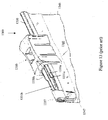
- FIG. 13 shows a reclosable plastic bag 1300, which includes first and second opposing body panels 1340 connected to each other along a pair of sides 1345, 1347 and a bottom, in which the bottom extends between the pair of sides.
- the plastic bag 1300 includes a fastener, such as engageable tracks or a zipper 1330, extending along a mouth formed opposite the bottom of the plastic bag.
- the zipper 1330 generally includes a male track 1330a and a female track 1330b.
- the male track includes a male profile having a first depending fin or flange 1331a extending downward from the male profile.
- the female track 1330b includes a female profile having a second depending fin or flange 1331b extending downward from the female profile.
- the first and second fins can be extruded separately from the body panels 1340 and then thermally fused to the respective first and second body panels 1340.
- the male and female tracks 1330a, 1330b are rolled or pressed into interlocking engagement so as to securely close the bag 1300.
- a plastic slider 1310 can be provided to ride along the tracks 1330 a, 1330b of the zipper 1330. If the slider 1310 is pulled in one direction, the bag 1300 is sealed closed; if the slider 1310 is pulled in the opposite direction, the bag 1300 is opened.
- a track end termination 1337 is usually desired. The termination 1337, among other things, strengthens the end of the zipper 1330, and prevents the slider 1310 from sliding off of the zipper 1330.
- Such termination 1337 can be in the form of a clip, as illustrated, or can be an integrally formed region of the tracks that is strong enough to meet the required design criteria. Such region can be made by fusing predetermined regions at the end of the zipper 1330, such as by heat or ultrasonic welding techniques.
- certain zippered resealable bags include a header portion extending beyond the resealable track and slider.
- the header can be sealed at its upper end by a packager or processor to form a resealable bag with a tamper-evident seal. This is desirable for consumer use to assure a secure seal, while the slider provides easy and reliable reclosable function.
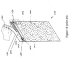
- Figure 14 illustrates an example of a reclosable bag 1400 having a slider 1427 and first and second header portions 1418 and 1482 divided by a line of weakness 1484, such as a perforation or thinned material region.
- the figure illustrates a bag 1400 that has been filled with a product 1480 and sealed along a top edge 1483.
- the user can tear the sealed upper header 1482 along the line of weakness 1484, with the lower header portion 1418 remaining in tact. Seals 1472 along the sides and bottom, which define the extent of a storage region of the bag, are unaltered.
- the user may reseal the bag 1400 using the provided slider 1427, which travels along the track 1416 of the reclosable fastener 1428.
- the invention includes, in one aspect, a fastener for a plastic bag that includes first and second mutually engageable track portions and a slider for engaging and disengaging the track portions.
- the slider includes a core portion and one or more end portions.
- the core portion is made of a first material having a first preselected material property.
- the one or more end portion(s) are made of a second material having a second preselected material property and is arranged at opposing ends of the slider.
- the first and second preselected material properties can be a preselected modulus of elasticity, hardness or other material property.
- the second material has a hardness and/or modulus of elasticity that are less than the first material.
- the core portion of the slider can be centrally located along a longitudinal axis of the slider.
- the core portion is made from polypropylene and the end portion of the slider is made of a thermoplastic elastomer.
- the end portion can include a separate member at each opposing end of the slider or two end portions joined together by a connecting element.
- the core portion and the end portion of the slider can be joined by a press-fit, integrally molded, joined by an interference fit, or a solvent or heat weld. If integrally molded, the end portion can be molded over the core portion, covering an exterior surface of the core portion or alternatively molded adjacent to the core portion.
- the invention includes, in another aspect, a slider for a plastic bag having a first track portion and a second track portion engageable with the first track portion.
- the slider is capable of engaging and disengaging the first track portion, respective the second track portion.
- the slider includes a core portion made of a first material, having a first preselected material property and an end portion made of a second material, having a second preselected material property. The end portion is arranged at opposing ends of the slider.
- the invention includes a method of processing a product in a plastic bag having a fastener with slider.
- the method includes providing a plastic bag having first and second track portions and a slider to engage and disengage the first track portion respective the second track portion, inserting a product into the plastic bag and processing the plastic bag and product in a pressurized environment.
- the slider includes a core portion made of a first material having a first preselected material property and an end portion made of a second material arranged at opposing ends of the slider.
- the second material has a second preselected material property.
- the invention includes a method of processing a product in a plastic bag comprising providing a plastic bag having a reclosable fastener with first and second track portions, inserting a product into the plastic bag, processing the plastic bag and product in a pressurized environment, and installing a slider on the reclosable fastener, the slider being capable of engaging and disengaging the first track portion respective the second track portion.
- the invention can further include processing the plastic bag and product by subjecting the plastic bag and product to a predetermined pressure, drying at least a predetermined region of the plastic bag, and sealing the plastic bag in the predetermined region.
- a method of packaging a product includes providing two opposing body panels, forming a pouch by sealing the body panels in a predetermined region, inserting a product to be sealed into the pouch, treating the product and the pouch in a predetermined process, affixing first and second track portions each to a respective body panel, and installing a slider on the first and second track portions.
- the treatment of the product can include subjecting the product and pouch to a predetermined pressure, wherein the predetermined pressure is higher than ambient pressure.
- the methods and systems presented herein can be used for packaging products, particularly in a pressurized environment.
- the methods and systems described herein are particularly suited for packaging food products undergoing high-pressure pasteurization or other pressurized processing.
- the methods and systems described herein can be used to enhance ergonomic aspects and improve the tactile sensation of sliders for reclosable packages.
- a slider for a reclosable bag having first and second, mutually engageable track portions.
- the slider engages and disengages the first and second track portions.
- the slider includes a core portion made of a first material, having a first predetermined hardness.
- the slider further includes at least one end portion made of a second material, arranged at opposing ends of the slider.
- the second material has a second predetermined hardness, which is less than the first predetermined hardness.
- a second predetermined hardness which is less than the first predetermined hardness.
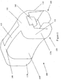
- the slider 100 is constructed to have properties of a soft material proximate its ends and a relatively hard material within the core portion, which is in engagement with the tracks of the bag on which the slider is mounted. This is preferably achieved by manufacturing the slider out of a plurality of materials but may be achieved in other manners, such as by altering the material properties of one or more selected portions of the slider by treating only that portion of the slider. For example, certain polymers can be hardened when subjected to ultraviolet light or by other cross-linking techniques.
- the slider 100 is advantageously manufactured in a multi-stage or "multi-shot" molding process.
- a first portion of the slider such as the core
- a second portion such as the end portion is molded.
- the second portion can be molded adjacently to the first portion, or can be molded to cover the first portion in part or in its entirety.
- Alternative manufacture techniques can be used to form and assemble the portions of the slider, if desired.
- portions of the slider can be manufactured from different materials to achieve a slider having tailored exterior material characteristics, even though such material might not otherwise be suitable for manufacture of an entire slider.
- the core and end portions can form a layer over a core portion.
- the core portion can be configured to form a "skeleton," such that material from the second and subsequent molding stages can cover and/or be injected between the core portion.
- the subject slider benefits from having a core portion that is sufficiently rigid to keep the slider from flexing and falling from a conventional track (such as illustrated in Figures 13 and 14 ), and having end portions that are sufficiently soft to comply with an applied pressure to the extent desired.
- the slider generally includes two portions.
- the core portion.150 provides a majority of the structure for and subsequent strength of the slider 100.
- the slider 100 is an inverted generally U-shaped member, as is the core portion 150, itself. Accordingly, when constructed from a sufficiently rigid material, the core portion 150 can retain the slider 100 on the track.
- the core portion 150 further provides the components that function to engage and disengage the track members described above.
- the second portion 110 of the slider embodied herein includes end portions 113a and 113b.
- a connecting rail 115 is formed along the spine of the slider 100 to connect the end portions. The connecting rail 115 thus facilitates assembly of the slider 100 with only two parts, if formed separately.
- the rail 115 provides a region at which the parts can be attached by desired means, including but not limited to an adhesive connection, press-fit, interference fit, mechanical interlocking, solvent welding, heat welding, sonic welding or another means that yields a sufficient bond to achieve the desired longevity and strength of the slider 100.
- the end portions 113a, 113b are integrally molded with the core portion 150 in a multi-stage or multi-shot molding process.
- the connecting rail 115 defines a bridge between two molded elements, advantageously eliminating the need for multiple injection nozzles that would otherwise be required, thereby reducing tooling costs.
- the connecting rail 115 therefore simplifies manufacture and assembly of the slider.
- separate end portions can be provided as two or more members to be attached to the core portion.
- the slider can be formed from a single member that is processed to create a more rigid core portion and less rigid end portions, if desired.
- the slider 100 as a whole, comprises a top 140, a pair of sides or side walls 116 and 118 depending downwardly from the top 140, and at least one separation member or finger 260 located on an underside of the top 140.
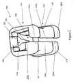
- the separation finger 260 is positioned between the sides 116 and 118, which is best seen from the bottom isometric view of the slider 100 depicted in Figure 2 .
- each side 116 and 118 are inwardly extending shoulders 220 and 240, respectively, which cooperate with the separation finger 260 to assist in opening and closing the fastener track on which the slider 100 is mounted.
- the shoulders 220 and 240 engage an underside of the fastener track to inhibit or prevent the slider 100 from being lifted off profile edges while the slider 100 straddles the fastener track.
- Alternative embodiments of finger and shoulder configurations can be used in accordance with the present invention, such as those described in U.S. Patent Publication Number 2005/0115033 and U.S. Patent Number 6,611,996 .
- the shoulders 220 and 240 are formed of shoulder segments 220a-220c and 240a-240c, respectively.
- the core portion 150 includes shoulder segments 220c and 240c.
- the second portion 110 includes the two end portions 113a,b.
- the first end portion 113a includes shoulder segments 220a and 240a.
- the second end portion 113b includes shoulder segments 220b and 240b.
- the separate shoulder segments work in conjunction to secure the slider 100 to the track.
- the shoulder segments 220c and 240c of the core portion 150 will constitute the majority of flexural rigidity and strength of the slider for preventing removal of the slider 100 from the track, whereas the remaining shoulder segments will minimize hard and/or sharp edges to minimize damage to the panels of the reclosable bag during processing, such as during high pressure pasteurization.
- the relatively rigid core portion 150 also helps maintain the slider 100 in alignment with the track, preventing the slider from "ridging" up or down, relative to the track, thereby also keeping the separating finger 260 in correct position, relative to the tracks.
- the separation finger 260 of the slider 100 generally has a wide portion 261 and a narrow portion 263.
- the separation finger 260 with the wide and narrow portions 261 and 263, respectively, interacts with mating portions of the fastener to engage or disengage the first and second profiles of the fastener. This interaction engages and disengages the fastener in the manner described in U.S. Pat. No. 5,007,143 , which is incorporated herein by reference in its entirety.
- the core portion 150 is made from a material that is sufficiently rigid to prevent undesired removal of the slider 100 from the track.
- the material is also preferably selected such that it interacts appropriately with the material of the track and the bag material itself. While the softer end portions 113a,b can contact the track and the bag, it is contemplated that the core portion 150 maintains the integrity of the mating relationship with the track. Accordingly, the material used for the core portion 150 preferably is relatively resistant to wear and fatigue. Since the inner channel 290 of the core portion 150 slides along the track, and the shoulders 220, 240 contact portions of the track and bag, the materials of the slider 100 and the bag and track are selected to be suitable to result in a smoothly sliding slider, having a relatively low coefficient of friction therebetween.
- the bag panels can be made from any of a variety of suitable films, such as, but not limited to polyethylene (PE), ethylene vinyl alcohol (EVOH), Nylon, polyethylene/polyethylene terephthalate laminates, polyethylene/polyethylene and ethylene vinyl alcohol laminates, coextruded polyethylene/polyethylene laminates, Nylon/polyethylene terephthalate/polyethylene laminates, or combinations thereof.
- PE polyethylene
- EVOH ethylene vinyl alcohol
- Nylon polyethylene/polyethylene terephthalate laminates
- polyethylene/polyethylene and ethylene vinyl alcohol laminates polyethylene/polyethylene and ethylene vinyl alcohol laminates
- coextruded polyethylene/polyethylene laminates Nylon/polyethylene terephthalate/polyethylene laminates, or combinations thereof.
- the track can be formed of the same material as the bag panel, or a different material, including, but not limited to low-density polyethylene (LDPE), high-density polyethylene (HDPE), ultra-low-density polyethylene (ULDPE), cyclic olefin copolymer, ethylene vinyl alcohol, or combinations thereof.
- LDPE low-density polyethylene
- HDPE high-density polyethylene
- ULDPE ultra-low-density polyethylene
- cyclic olefin copolymer ethylene vinyl alcohol, or combinations thereof.
- the core portion of the slider 150 can be made from any suitable plastic such as polypropylene, a urethane material, a polyethylene material, polybutylene terephthalate (PBT), polyethylene terephthalate, Nylon, acetal or combinations thereof, while the end portions 113a,b are made from a softer plastic, such as a urethane material, rubber, thermoplastic olefin (TPO), very low density polyethylene (VLDPE) or plastomers but preferably a thermoplastic elastomer (TPE).
- TPO thermoplastic olefin
- VLDPE very low density polyethylene
- TPE thermoplastic elastomer
- the end portions in certain embodiments, are preferably made from a material having a hardness of about 50-90 +/- 5 on the Shore A scale or about 12-40 +/- 5 on the Shore D scale, or an equivalent hardness as otherwise measured.
- the modulus of elasticity for materials used in the core portion can range from about 600 MPa to about 4000MPa, but preferably is about 1600 MPa, and the modulus of elasticity for materials used in the end portions can range from about 1 MPa to about 35 MPa, but preferably is about 7 MPa.
- the end portions 113a, 113b are of a material softer than the core portion, so as to provide a relatively soft the edge for the slider 100.
- the end portions preferably have a smoothly contoured profile, such as shown for purpose of example, and are constructed of a relatively soft material, compared with the relatively stiff or rigid material of the core portion 150 that is necessary to impart the desired resistance to flexure and wear.
- the second portion 110 including end portions 113a, 113b, is constructed from a material that is compliant under the contemplated treatment conditions. When treating the bag and an item contained in the bag under an increased pressure or increased pressure and temperature, it is desired that the ends of the slider do not impart holes in an overlying polymeric film, such as a header portion of a bag.
- sliders in accordance with at least one embodiment of the invention can be configured to enhance ergonomic aspects of sliders of reclosable containers.
- a material that provides a favorable tactile sensation to the user can be utilized.
- rubber and rubber-like materials provide a secure, slip-resistant grip, such materials are usually relatively soft and therefore not suitable for the core portion. Accordingly, providing a slider made from multiple materials can advantageously result in a slider with desirable characteristics in one portion, while accommodating alternate desired characteristics in another portion.
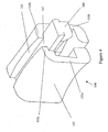
- Figure 3 more clearly illustrates the second portion 110 of the slider 100, illustrated in Figure 1 , which in this embodiment includes end portions 113a,b and connecting rail 115.
- the second portion 110 is illustrated alone, without the core portion 150 for clarity.
- Any of a variety of suitable alternative configurations having a smooth contour, preferably without exposed sharp corners, can be used.
- these portions can be fabricated separately and then assembled, or can be formed by multi-stage molding techniques, or of a single material that is selectively processed, such as by cross-linking, to form the desired portions.
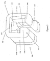
- Figure 4 illustrates the core portion 150 of the embodiment of Figure 1 , alone for clarity.
- the core portion includes a groove 155 into which the rail portion 115 of the second portion 110 is secured or integrally formed, such as in a multi-stage molding process.
- the core portion 150 includes one or more connecting members 157 between core halves 151a and 151b. Such a connecting member can span between upper edges 153a and 153b so that the core halves 151a and 151b are formed as a single unit.
- the core portion 150 can be constructed in two separate halves and held together through attachment to the rail 115 of the second portion 110, if made of suitable materials.
- the separating finger 260 is integrally formed with the core portion 150 and extends beyond the core halves 151a and 151b. In this manner, the harder, more wear resistant material of the core portion contacts the track, rather than the softer material of the end portions.
- the protruding separating finger is disposed within a recess 160 in the underside of one end portion 113a, as seen in figure 3 .
- the end portion 113a generally covers or wraps around the exterior portion of the protruding separating finger 260, thereby preventing the relative rigidity of the separating finger 260 from damaging the plastic bag during processing.
- the slider is preferably made of material suitable for withstanding high pressure and/or high temperature environments.
- the conditions that the end portions 113a,b can experience include a pressure of between about 50 psi and 100,000 psi, typically between 50 psi and 89,000 psi, and/or a temperature between about 34°F and 130°F, for a period of time between about 0 and 300 seconds. A process time of approximately 3 minutes is typical. These ranges are for the purpose of providing examples and not limitation.
- the materials used therefore, can be selected according to the specific conditions under which a specific bag is to be treated. As set forth above, however, materials also can be chosen based on the tactile or aesthetic sensation desired.
- the slider of at least one embodiment of the present invention is constructed with properties of both soft and hard materials; specifically, a soft portion at its ends, and yet the overall rigidity capable of retaining the slider on the track on which it is mounted.
- this can be accomplished by providing a core portion made from a first material and second portion made of a different material, each having the prescribed material properties.
- the slider can be made of a single material having a portion of the slider 150 that is treated to alter its material properties.
- the slider can be constructed from a material that is hardened by a specific frequency of electromagnetic radiation, such as ultraviolet light, or treated through a chemical process to achieve such result.
- a portion such as the central region illustrated in the above figures as the core region 150, can be subjected to such radiation, while the ends 113a, 113b are substantially shielded from such radiation.
- a slider having dual properties but a single material can be achieved.
- the desired properties of the slider can be imparted by providing the slider with an internal skeleton having a more rigid structure to achieve the necessary flexural rigidity for the slider, and then over-molding the skeleton with a relatively soft material to provide the desired end characteristics.
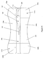
- Figures 5-12 illustrate a preferred embodiment of the subject slider.
- the embodiment of these figures is generally similar to that of Figures 1-4 , although the separating finger or "plow" 560 is set back by a distance 605 ( Figure 6 ) from a rear edge 519 of the slider. This relative positioning is particularly advantageous in very high-pressure environments by further concealing the separating finger 560 from contact with any portion of the bag film.
- Figures 5-8 respectively illustrate isometric, bottom, rear end and front end views of a slider in accordance with at least one embodiment of the invention, wherein the separating finger 560 is set back from the edge of the slider.
- the separating finger 560 includes a wide end 561 and a narrow end 563.
- the subject slider of this embodiment also benefits from having a core portion that is sufficiently rigid to keep the slider from flexing and detaching from a track, and having end portions that are sufficiently soft to comply with an applied pressure to the extent desired when undergoing treatment.
- the slider 500 includes two portions.
- the core portion 550 provides a majority of the structure for and subsequent strength of the slider 500.
- the slider 500 is an inverted generally U-shaped member, as is the core portion 550. When constructed from a sufficiently rigid material, the core portion 550 can retain the slider 500 on the track (shown in Figures 13-14 ).
- the core portion 550 further provides the components that function to engage and disengage the track members described above.
- the second portion 510 of the slider 500 includes end portions 513a and 513b.
- a connecting rail 715 can be provided along the spine of the slider 500 to connect the end portions. The connecting rail 715 facilitates assembly of the slider 500, allowing the use of only two portions, as previously described.
- the rail 715 also provides a region at which the portions can be attached by desired means, including but not limited to an adhesive connection, press-fit, interference fit, mechanical interlocking, solvent welding, heat welding or another means that yields a sufficient bond strength to achieve the desired longevity and strength of the slider 500.
- the end portions 513a, 513b are integrally molded with the core portion 550 in a multi-stage or "multi-shot" molding process.
- the connecting rail 715 defines as a bridge between two molded elements, advantageously eliminating the need for multiple injection nozzles that would otherwise be required, thereby reducing tooling costs.
- the connecting rail 715 allows the use of only one injection nozzle to inject the material for each of the end portions 513a, 513b, rather than a dedicated nozzle for each portion.
- the connecting rail 715 therefore simplifies manufacture and assembly of the slider. If desired, however, separate end portions can be provided as two or more members to be molded on or otherwise attached to the core portion.
- the slider can be formed from a single member that is processed to create a more rigid core portion and less rigid end portions, if desired.
- the slider 500 as a whole, includes a top 540, a pair of sides or side walls 516 and 518 depending downwardly from the top 540, and at least one separation member or finger 560 located on an underside of the top 540.
- the separation finger 560 is positioned between the sides 516 and 518, which is best seen from the bottom isometric view of the slider 500 depicted in Figure 6 .
- each side 516 and 518 are inwardly extending shoulders 520 and 540, respectively, which cooperate with the separation finger 560 to assist in opening and closing the fastener track on which the slider 500 is mounted.
- the shoulders 520 and 540 engage an underside of the fastener track to inhibit or prevent the slider 500 from being lifted off profile edges while the slider 500 straddles the fastener track.
- Alternative embodiments of finger and shoulder configurations can be used in accordance with the present invention.
- the shoulders 520 and 540 are formed of shoulder segments 520 a-c and 540a-c, respectively.
- the core portion 550 includes shoulder segments 520c and 540c.
- the second portion 510 includes the two end portions 513a,b.
- the first end portion 513a includes shoulder segments 520a and 540a.
- the second end portion 513b includes shoulder segments 520b and 540b.
- the separate shoulder segments work in conjunction to secure the slider 500 to the track.
- the shoulder segments 520c and 540c of the core portion 550 will constitute the majority of flexural rigidity and strength of the slider for preventing removal of the slider 500 from the track, whereas the remaining shoulder segments will minimize hard and/or sharp edges to minimize damage to the panels of the reclosable bag during processing.
- the relatively rigid core portion 550 also helps maintain the slider 500 in alignment with the track, preventing the slider from "riding" up or down, relative to the track, thereby also keeping the separating finger 560 in correct position, relative to the tracks.
- the height of the channel 590 ( Figures 5-7 ) into which the track fits, is higher on one side than the other. That is, in Figure 7 , the channel 590 is higher on the side of the slider near shoulder 540a, than it is near 520a. This configuration allows for the appropriate geometry to allow the reclosable tracks to engage and disengage one another.
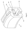
- Figure 9 illustrates a core portion 550 of the embodiment of the slider,shown in Figures 5-8 .
- the separating finger 560 protrudes slightly from below an end face 959 of the core portion 550.
- the separating finger 560 is disposed away from the edge 519 of the slider to minimize damage to the film during high pressure processing. If desired, the separating finger 560 need not extend past the face 959 of the core portion 550.
- the channel 955 provides an interface for the rail 715 of the end portion 510 and/or a passageway for material to flow when the slider 500 is molded in a multi-stage molding process.
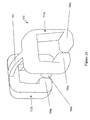
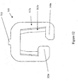
- Figures 10-12 illustrate isometric, side and end views, respectively, of the second portion 510 of the embodiment of the slider shown in Figures 5-8 .
- the second portion 510 of the slider 500 in this embodiment includes end portions 513a,b and connecting rail 715.
- the second portion 510 is illustrated alone, without the core portion 550 for clarity. Any of a variety of suitable alternative configurations and constructions to provide a smooth contour, preferably without exposed sharp corners, can be used, as previously described.
- a method of processing a product in a plastic bag having a fastener includes providing a plastic bag having first and second track portions and a slider to engage and disengage the first track portion respective the second track portion.
- the slider includes a core portion made of a first material having a first predetermined hardness and an end portion made of a second material, preferably arranged at opposing ends of the slider.
- the second material has a second predetermined hardness, which is less than the first predetermined hardness.
- the method further includes inserting a product into the plastic bag and processing the plastic bag and product in a pressurized environment, such as high pressure pasteurization as is known.
- the method can further include processing the plastic bag and product by bringing the plastic bag and product to a predetermined pressure and/or a predetermined temperature, drying at least a predetermined region of the plastic bag and sealing the plastic bag in the predetermined region.
- the method can include treating the product and reclosable bag prior to affixing the first and second track portions to the panels of the bag. In this manner, a slider having end portions formed of less rigid material is not required, although still preferred.
- a method of processing a product can include treating the product and reclosable bag prior to affixing the slider to the panels of the bag. In this manner, a slider having end portions formed of less rigid material is not required.
- a closure system including a slider and track portion.
- the system includes, in addition to the slider described herein, a track made from preselected materials and/or having a preselected shape to inhibit damage to package films undergoing high pressure processing.
- a track made from preselected materials and/or having a preselected shape to inhibit damage to package films undergoing high pressure processing.
- male and female tracks can be provided made entirely or partially from a relatively soft material. In this manner, softer materials can be utilized throughout or only in regions of the tracks that come into close contact with packaging film.
- a geometry can be provided such that the tracks have smoother contours than would otherwise provided in existing tracks for reclosable fasteners. In this manner, damage to packaging films can be further prevented for packages undergoing high pressure processing.
Claims (18)
- Élément de fixation pour un sac en plastique comprenant :une première partie de glissière ;une deuxième partie de glissière pouvant s'engager dans la première partie de glissière ; etun élément coulissant (100) pour engager et désengager la première partie de glissière par rapport à la deuxième partie de glissière, l'élément coulissant (100) comprenant :une partie centrale (150) constituée d'un premier matériau présentant une première dureté ; etdes parties d'extrémité (113a, 113b) constituées d'un deuxième matériau, disposées à des extrémités opposées de l'élément coulissant (100) le long de son axe longitudinal, le deuxième matériau présentant une deuxième dureté, caractérisé en ce que la deuxième dureté est inférieure à la première dureté.
- Élément de fixation selon la revendication 1, dans lequel le premier matériau présente un premier module d'élasticité et le deuxième matériau présente un deuxième module d'élasticité.
- Élément de fixation selon la revendication 2, dans lequel le deuxième module d'élasticité est inférieur au premier module d'élasticité.
- Élément de fixation selon l'une quelconque des revendications précédentes, dans lequel la partie centrale (150) de l'élément coulissant (100) est située de manière centrale le long d'un axe longitudinal de l'élément coulissant (100).
- Élément de fixation selon l'une quelconque des revendications précédentes, dans lequel la partie centrale (150) de l'élément coulissant (100) est constituée de polypropylène.
- Élément de fixation selon l'une quelconque des revendications précédentes, dans lequel les parties d'extrémité (113a, 113b) de l'élément coulissant (100) sont constituées d'un élastomère thermoplastique.
- Élément de fixation selon la revendication 6, dans lequel les parties d'extrémité (113a, 113b) comprennent un élément séparé à chaque extrémité opposée de l'élément coulissant (100).
- Élément de fixation selon l'une quelconque des revendications précédentes, dans lequel la partie centrale (150) et les parties d'extrémité (113a, 113b) de l'élément coulissant (100), sont assemblées par un ajustement par pression.
- Élément de fixation selon l'une quelconque des revendications précédentes 1 à 7, la partie centrale (150) et les parties d'extrémité (113a, 113b) de l'élément coulissant (100) sont moulées de manière solidaire.
- Élément de fixation selon l'une quelconque des revendications précédentes 1 à 7, dans lequel les parties d'extrémité (113a, 113b) sont moulées sur la partie centrale (150), recouvrant ainsi une surface extérieure de la partie centrale (150).
- Élément de fixation selon l'une quelconque des revendications précédentes 1 à 7, dans lequel la partie centrale (150) et les parties d'extrémité (113a, 113b) de l'élément coulissant (100) sont assemblées par un ajustement avec serrage, par une soudure par solvant ou par une thermosoudure.
- Élément coulissant pour un sac en plastique présentant une première partie de glissière et une deuxième partie de glissière pouvant s'engager dans la première partie de glissière, l'élément coulissant pouvant engager et désengager la première partie de glissière, par rapport à la deuxième partie de glissière, l'élément coulissant (100) comprenant :une partie centrale (150), constituée d'un premier matériau, présentant une première dureté ; etdes parties d'extrémité (113a, 113b) constituées d'un deuxième matériau, disposées à des extrémités opposées de l'élément coulissant le long de son axe longitudinal, le deuxième matériau présentant une deuxième dureté, caractérisé en ce que la deuxième dureté est inférieure à la première dureté.
- Élément coulissant selon la revendication 12, dans lequel le premier matériau présente un premier module d'élasticité et le deuxième matériau présente un deuxième module d'élasticité.
- Élément coulissant selon la revendication 13, dans lequel le deuxième module d'élasticité est inférieur au premier module d'élasticité.
- Élément coulissant pour un sac en plastique présentant une première partie de glissière et une deuxième partie de glissière pouvant s'engager dans la première partie de glissière, l'élément coulissant pouvant engager et désengager la première partie de glissière par rapport à la deuxième partie de glissière, l'élément coulissant (500) comprenant :une première partie (550) constituée d'un premier matériau présentant une première dureté, et présentant des extrémités opposées le long d'un axe longitudinal de l'élément coulissant ; etune deuxième partie (510), constituée d'un deuxième matériau, disposée au moins sur une partie de la première partie (550), la deuxième partie (510) est disposée au moins sur les extrémités opposées de la première partie (550), le deuxième matériau présentant une deuxième dureté, caractérisé en ce que la deuxième dureté est inférieure à la première dureté.
- Élément coulissant selon la revendication 15, dans lequel la deuxième partie (510) est disposée sur une surface extérieure de la première partie (550) sensiblement dans sa globalité.
- Procédé de traitement d'un produit dans un sac en plastique présentant un élément de fixation avec un élément coulissant consistant ;à prévoir un sac en plastique présentant les première et deuxième parties de glissière à proximité d'une ouverture du sac et un élément coulissant (500) pour engager et désengager la première partie de glissière par rapport à la deuxième partie de glissière, l'élément coulissant (500) comprenant :une première partie (550), constituée d'un premier matériau, présentant une première dureté, et présentant des extrémités opposées le long d'un axe longitudinal de l'élément coulissant etune deuxième partie (510), constituée d'un deuxième matériau, disposée au moins sur une partie de la première partie (550), la deuxième partie (510) est disposée au moins sur les extrémités opposées de la première partie (550), le deuxième matériau présentant une deuxième dureté, la deuxième dureté étant inférieure à la première dureté ;à insérer un produit dans le sac en plastique ; età traiter le sac en plastique et le produit dans un environnement sous pression.
- Procédé selon la revendication 17, dans lequel la deuxième partie (510) est disposée sur une surface extérieure de la première partie (550) sensiblement dans sa globalité.
Applications Claiming Priority (2)
| Application Number | Priority Date | Filing Date | Title |
|---|---|---|---|
| US75264805P | 2005-12-20 | 2005-12-20 | |
| PCT/US2006/062417 WO2007111750A2 (fr) | 2005-12-20 | 2006-12-20 | Element de fixation refermable pourvu d'un organe coulissant pour un traitement haute pression |
Publications (2)
| Publication Number | Publication Date |
|---|---|
| EP1968411A2 EP1968411A2 (fr) | 2008-09-17 |
| EP1968411B1 true EP1968411B1 (fr) | 2010-03-17 |
Family
ID=38474444
Family Applications (1)
| Application Number | Title | Priority Date | Filing Date |
|---|---|---|---|
| EP06850335A Not-in-force EP1968411B1 (fr) | 2005-12-20 | 2006-12-20 | Element de fixation refermable pourvu d'un organe coulissant pour un traitement haute pression |
Country Status (6)
| Country | Link |
|---|---|
| US (1) | US7946004B2 (fr) |
| EP (1) | EP1968411B1 (fr) |
| AT (1) | ATE460855T1 (fr) |
| CA (1) | CA2632600C (fr) |
| DE (1) | DE602006013043D1 (fr) |
| WO (1) | WO2007111750A2 (fr) |
Families Citing this family (8)
| Publication number | Priority date | Publication date | Assignee | Title |
|---|---|---|---|---|
| WO2009055634A1 (fr) * | 2007-10-24 | 2009-04-30 | Neostim Inc. | Contrôle intrasession de stimulation magnétique transcrânienne |
| US8245364B2 (en) * | 2008-04-23 | 2012-08-21 | S.C. Johnson & Son, Inc. | Closure mechanism having internal projections to decrease slider pull-off |
| HUE035936T2 (en) * | 2013-04-09 | 2018-05-28 | Reynolds Presto Products Inc | Child-proof zipper with integrated torpedo element and related procedures |
| US10227163B2 (en) * | 2014-08-29 | 2019-03-12 | Interplast Group Corporation | Audible slidable zipper bags |
| USD815957S1 (en) | 2015-06-19 | 2018-04-24 | S. C. Johnson & Son, Inc. | Slider bag |
| USD837831S1 (en) | 2015-06-19 | 2019-01-08 | S.C. Johnson & Son, Inc. | Slider |
| CN110150799B (zh) * | 2018-02-15 | 2021-12-24 | 易嘉然 | 轨道拉链及具有该轨道拉链的连接结构 |
| US11077989B2 (en) * | 2019-06-21 | 2021-08-03 | Reynolds Presto Products Inc. | Slider device, zipper closure system, and methods of use |
Family Cites Families (8)
| Publication number | Priority date | Publication date | Assignee | Title |
|---|---|---|---|---|
| US3103049A (en) * | 1960-06-21 | 1963-09-10 | E P S Res & Dev Ltd | Slide fasteners and protective containers |
| US5010627A (en) * | 1990-03-07 | 1991-04-30 | Mobil Oil Corporation | Foldable plastic slider and method of assembly with a plastic reclosable fastener |
| AU645414B2 (en) * | 1991-04-27 | 1994-01-13 | Ykk Corporation | Slider with yoke for slide fastener and its joining method |
| WO2000076347A1 (fr) * | 1999-06-10 | 2000-12-21 | The Glad Products Company | Dispositif de fermeture |
| US7269883B2 (en) * | 2001-03-22 | 2007-09-18 | The Clorox Company | Closure device |
| US6611996B2 (en) * | 2001-07-02 | 2003-09-02 | Pactiv Corporation | Slider for reclosable fastener |
| US7251864B2 (en) * | 2004-01-28 | 2007-08-07 | Chia-Hsiang Chang | Two piece and assembleable slider for application to resealable portions associated with a plastic bag |
| US20060168777A1 (en) * | 2005-01-31 | 2006-08-03 | Turvey Robert R | Slider for a reclosable pouch |
-
2006
- 2006-12-20 AT AT06850335T patent/ATE460855T1/de not_active IP Right Cessation
- 2006-12-20 EP EP06850335A patent/EP1968411B1/fr not_active Not-in-force
- 2006-12-20 CA CA2632600A patent/CA2632600C/fr not_active Expired - Fee Related
- 2006-12-20 DE DE602006013043T patent/DE602006013043D1/de active Active
- 2006-12-20 US US11/613,642 patent/US7946004B2/en active Active
- 2006-12-20 WO PCT/US2006/062417 patent/WO2007111750A2/fr active Application Filing
Also Published As
| Publication number | Publication date |
|---|---|
| DE602006013043D1 (de) | 2010-04-29 |
| WO2007111750A3 (fr) | 2007-11-22 |
| CA2632600A1 (fr) | 2007-10-04 |
| CA2632600C (fr) | 2014-06-10 |
| EP1968411A2 (fr) | 2008-09-17 |
| ATE460855T1 (de) | 2010-04-15 |
| US7946004B2 (en) | 2011-05-24 |
| WO2007111750A2 (fr) | 2007-10-04 |
| US20070193000A1 (en) | 2007-08-23 |
Similar Documents
| Publication | Publication Date | Title |
|---|---|---|
| EP1968411B1 (fr) | Element de fixation refermable pourvu d'un organe coulissant pour un traitement haute pression | |
| US10793322B2 (en) | Multiple zipper slider bag | |
| EP1587738B1 (fr) | Scellement pour sac a glissiere | |
| EP1449783B1 (fr) | Ensemble fermeture à glissière avec curseur pour un emballage refermable | |
| US6595689B1 (en) | Closure device | |
| US20040136618A1 (en) | Watertight slider-zipper assembly for reclosable packaging | |
| US20040045134A1 (en) | Closure device | |
| EP1761438A2 (fr) | Fermeture anti-fuites a ressort | |
| WO2004009465A1 (fr) | Butee d'extremite pour fermeture eclair de sac | |
| US6840675B2 (en) | Reclosable packaging having zipper with sculpted slider end stops | |
| US20140093191A1 (en) | Slider for sealing and unsealing a storage bag | |
| AU766321B2 (en) | Closure device | |
| US6981299B2 (en) | Closure device | |
| US8882349B2 (en) | End stops for reclosable fastener and reclosable bag having same | |
| US6728997B1 (en) | Closure device | |
| WO2012064688A2 (fr) | Fermeture à glissière refermable dotée d'organes d'étanchéité coextrudés | |
| CA2381063C (fr) | Recipient avec dispositif de fermeture et joints lateraux multiples | |
| AU776194B2 (en) | Closure device | |
| WO2005070777A1 (fr) | Butee d'arret pour un sachet refermable, et son procede de production | |
| WO2002062672A1 (fr) | Dispositif de fermeture |
Legal Events
| Date | Code | Title | Description |
|---|---|---|---|
| PUAI | Public reference made under article 153(3) epc to a published international application that has entered the european phase |
Free format text: ORIGINAL CODE: 0009012 |
|
| 17P | Request for examination filed |
Effective date: 20080331 |
|
| AK | Designated contracting states |
Kind code of ref document: A2 Designated state(s): AT BE BG CH CY CZ DE DK EE ES FI FR GB GR HU IE IS IT LI LT LU LV MC NL PL PT RO SE SI SK TR |
|
| 17Q | First examination report despatched |
Effective date: 20090312 |
|
| GRAP | Despatch of communication of intention to grant a patent |
Free format text: ORIGINAL CODE: EPIDOSNIGR1 |
|
| GRAS | Grant fee paid |
Free format text: ORIGINAL CODE: EPIDOSNIGR3 |
|
| GRAA | (expected) grant |
Free format text: ORIGINAL CODE: 0009210 |
|
| AK | Designated contracting states |
Kind code of ref document: B1 Designated state(s): AT BE BG CH CY CZ DE DK EE ES FI FR GB GR HU IE IS IT LI LT LU LV MC NL PL PT RO SE SI SK TR |
|
| REG | Reference to a national code |
Ref country code: GB Ref legal event code: FG4D |
|
| REG | Reference to a national code |
Ref country code: CH Ref legal event code: EP |
|
| REG | Reference to a national code |
Ref country code: IE Ref legal event code: FG4D |
|
| REF | Corresponds to: |
Ref document number: 602006013043 Country of ref document: DE Date of ref document: 20100429 Kind code of ref document: P |
|
| REG | Reference to a national code |
Ref country code: NL Ref legal event code: VDEP Effective date: 20100317 |
|
| PG25 | Lapsed in a contracting state [announced via postgrant information from national office to epo] |
Ref country code: LT Free format text: LAPSE BECAUSE OF FAILURE TO SUBMIT A TRANSLATION OF THE DESCRIPTION OR TO PAY THE FEE WITHIN THE PRESCRIBED TIME-LIMIT Effective date: 20100317 |
|
| LTIE | Lt: invalidation of european patent or patent extension |
Effective date: 20100317 |
|
| PG25 | Lapsed in a contracting state [announced via postgrant information from national office to epo] |
Ref country code: SI Free format text: LAPSE BECAUSE OF FAILURE TO SUBMIT A TRANSLATION OF THE DESCRIPTION OR TO PAY THE FEE WITHIN THE PRESCRIBED TIME-LIMIT Effective date: 20100317 Ref country code: PL Free format text: LAPSE BECAUSE OF FAILURE TO SUBMIT A TRANSLATION OF THE DESCRIPTION OR TO PAY THE FEE WITHIN THE PRESCRIBED TIME-LIMIT Effective date: 20100317 Ref country code: LV Free format text: LAPSE BECAUSE OF FAILURE TO SUBMIT A TRANSLATION OF THE DESCRIPTION OR TO PAY THE FEE WITHIN THE PRESCRIBED TIME-LIMIT Effective date: 20100317 Ref country code: FI Free format text: LAPSE BECAUSE OF FAILURE TO SUBMIT A TRANSLATION OF THE DESCRIPTION OR TO PAY THE FEE WITHIN THE PRESCRIBED TIME-LIMIT Effective date: 20100317 Ref country code: AT Free format text: LAPSE BECAUSE OF FAILURE TO SUBMIT A TRANSLATION OF THE DESCRIPTION OR TO PAY THE FEE WITHIN THE PRESCRIBED TIME-LIMIT Effective date: 20100317 |
|
| PG25 | Lapsed in a contracting state [announced via postgrant information from national office to epo] |
Ref country code: ES Free format text: LAPSE BECAUSE OF FAILURE TO SUBMIT A TRANSLATION OF THE DESCRIPTION OR TO PAY THE FEE WITHIN THE PRESCRIBED TIME-LIMIT Effective date: 20100628 Ref country code: SE Free format text: LAPSE BECAUSE OF FAILURE TO SUBMIT A TRANSLATION OF THE DESCRIPTION OR TO PAY THE FEE WITHIN THE PRESCRIBED TIME-LIMIT Effective date: 20100317 Ref country code: RO Free format text: LAPSE BECAUSE OF FAILURE TO SUBMIT A TRANSLATION OF THE DESCRIPTION OR TO PAY THE FEE WITHIN THE PRESCRIBED TIME-LIMIT Effective date: 20100317 Ref country code: NL Free format text: LAPSE BECAUSE OF FAILURE TO SUBMIT A TRANSLATION OF THE DESCRIPTION OR TO PAY THE FEE WITHIN THE PRESCRIBED TIME-LIMIT Effective date: 20100317 Ref country code: GR Free format text: LAPSE BECAUSE OF FAILURE TO SUBMIT A TRANSLATION OF THE DESCRIPTION OR TO PAY THE FEE WITHIN THE PRESCRIBED TIME-LIMIT Effective date: 20100618 Ref country code: EE Free format text: LAPSE BECAUSE OF FAILURE TO SUBMIT A TRANSLATION OF THE DESCRIPTION OR TO PAY THE FEE WITHIN THE PRESCRIBED TIME-LIMIT Effective date: 20100317 Ref country code: CY Free format text: LAPSE BECAUSE OF FAILURE TO SUBMIT A TRANSLATION OF THE DESCRIPTION OR TO PAY THE FEE WITHIN THE PRESCRIBED TIME-LIMIT Effective date: 20100317 Ref country code: BE Free format text: LAPSE BECAUSE OF FAILURE TO SUBMIT A TRANSLATION OF THE DESCRIPTION OR TO PAY THE FEE WITHIN THE PRESCRIBED TIME-LIMIT Effective date: 20100317 |
|
| PG25 | Lapsed in a contracting state [announced via postgrant information from national office to epo] |
Ref country code: IS Free format text: LAPSE BECAUSE OF FAILURE TO SUBMIT A TRANSLATION OF THE DESCRIPTION OR TO PAY THE FEE WITHIN THE PRESCRIBED TIME-LIMIT Effective date: 20100717 Ref country code: BG Free format text: LAPSE BECAUSE OF FAILURE TO SUBMIT A TRANSLATION OF THE DESCRIPTION OR TO PAY THE FEE WITHIN THE PRESCRIBED TIME-LIMIT Effective date: 20100617 Ref country code: CZ Free format text: LAPSE BECAUSE OF FAILURE TO SUBMIT A TRANSLATION OF THE DESCRIPTION OR TO PAY THE FEE WITHIN THE PRESCRIBED TIME-LIMIT Effective date: 20100317 Ref country code: SK Free format text: LAPSE BECAUSE OF FAILURE TO SUBMIT A TRANSLATION OF THE DESCRIPTION OR TO PAY THE FEE WITHIN THE PRESCRIBED TIME-LIMIT Effective date: 20100317 |
|
| PLBE | No opposition filed within time limit |
Free format text: ORIGINAL CODE: 0009261 |
|
| STAA | Information on the status of an ep patent application or granted ep patent |
Free format text: STATUS: NO OPPOSITION FILED WITHIN TIME LIMIT |
|
| PG25 | Lapsed in a contracting state [announced via postgrant information from national office to epo] |
Ref country code: PT Free format text: LAPSE BECAUSE OF FAILURE TO SUBMIT A TRANSLATION OF THE DESCRIPTION OR TO PAY THE FEE WITHIN THE PRESCRIBED TIME-LIMIT Effective date: 20100719 Ref country code: DK Free format text: LAPSE BECAUSE OF FAILURE TO SUBMIT A TRANSLATION OF THE DESCRIPTION OR TO PAY THE FEE WITHIN THE PRESCRIBED TIME-LIMIT Effective date: 20100317 |
|
| 26N | No opposition filed |
Effective date: 20101220 |
|
| PG25 | Lapsed in a contracting state [announced via postgrant information from national office to epo] |
Ref country code: IT Free format text: LAPSE BECAUSE OF FAILURE TO SUBMIT A TRANSLATION OF THE DESCRIPTION OR TO PAY THE FEE WITHIN THE PRESCRIBED TIME-LIMIT Effective date: 20100317 |
|
| PG25 | Lapsed in a contracting state [announced via postgrant information from national office to epo] |
Ref country code: MC Free format text: LAPSE BECAUSE OF NON-PAYMENT OF DUE FEES Effective date: 20101231 |
|
| REG | Reference to a national code |
Ref country code: CH Ref legal event code: PL |
|
| PG25 | Lapsed in a contracting state [announced via postgrant information from national office to epo] |
Ref country code: LI Free format text: LAPSE BECAUSE OF NON-PAYMENT OF DUE FEES Effective date: 20101231 Ref country code: CH Free format text: LAPSE BECAUSE OF NON-PAYMENT OF DUE FEES Effective date: 20101231 Ref country code: IE Free format text: LAPSE BECAUSE OF NON-PAYMENT OF DUE FEES Effective date: 20101220 |
|
| PG25 | Lapsed in a contracting state [announced via postgrant information from national office to epo] |
Ref country code: LU Free format text: LAPSE BECAUSE OF NON-PAYMENT OF DUE FEES Effective date: 20101220 Ref country code: HU Free format text: LAPSE BECAUSE OF FAILURE TO SUBMIT A TRANSLATION OF THE DESCRIPTION OR TO PAY THE FEE WITHIN THE PRESCRIBED TIME-LIMIT Effective date: 20100918 |
|
| PG25 | Lapsed in a contracting state [announced via postgrant information from national office to epo] |
Ref country code: TR Free format text: LAPSE BECAUSE OF FAILURE TO SUBMIT A TRANSLATION OF THE DESCRIPTION OR TO PAY THE FEE WITHIN THE PRESCRIBED TIME-LIMIT Effective date: 20100317 |
|
| REG | Reference to a national code |
Ref country code: FR Ref legal event code: TP Owner name: REYNOLDS PRESTO PRODUCTS INC., US Effective date: 20140318 |
|
| REG | Reference to a national code |
Ref country code: FR Ref legal event code: PLFP Year of fee payment: 10 |
|
| REG | Reference to a national code |
Ref country code: FR Ref legal event code: PLFP Year of fee payment: 11 |
|
| REG | Reference to a national code |
Ref country code: FR Ref legal event code: PLFP Year of fee payment: 12 |
|
| REG | Reference to a national code |
Ref country code: GB Ref legal event code: 732E Free format text: REGISTERED BETWEEN 20191212 AND 20191218 |
|
| REG | Reference to a national code |
Ref country code: DE Ref legal event code: R081 Ref document number: 602006013043 Country of ref document: DE Owner name: REYNOLDS PRESTO PRODUCTS INC., LAKE FOREST, US Free format text: FORMER OWNER: PACTIV CORP., LAKE FOREST, ILL., US |
|
| REG | Reference to a national code |
Ref country code: DE Ref legal event code: R081 Ref document number: 602006013043 Country of ref document: DE Owner name: REYNOLDS PRESTO PRODUCTS INC., LAKE FOREST, US Free format text: FORMER OWNER: PACTIVE LLC, LAKE FOREST, IL, US |
|
| REG | Reference to a national code |
Ref country code: DE Ref legal event code: R081 Ref document number: 602006013043 Country of ref document: DE Owner name: REYNOLDS PRESTO PRODUCTS INC., LAKE FOREST, US Free format text: FORMER OWNER: REYNOLDS CONSUMER PRODUCTS, INC., LAKE FOREST, ILL., US |
|
| PGFP | Annual fee paid to national office [announced via postgrant information from national office to epo] |
Ref country code: FR Payment date: 20201229 Year of fee payment: 15 Ref country code: GB Payment date: 20201228 Year of fee payment: 15 |
|
| PGFP | Annual fee paid to national office [announced via postgrant information from national office to epo] |
Ref country code: DE Payment date: 20210224 Year of fee payment: 15 |
|
| REG | Reference to a national code |
Ref country code: DE Ref legal event code: R119 Ref document number: 602006013043 Country of ref document: DE |
|
| GBPC | Gb: european patent ceased through non-payment of renewal fee |
Effective date: 20211220 |
|
| PG25 | Lapsed in a contracting state [announced via postgrant information from national office to epo] |
Ref country code: GB Free format text: LAPSE BECAUSE OF NON-PAYMENT OF DUE FEES Effective date: 20211220 Ref country code: DE Free format text: LAPSE BECAUSE OF NON-PAYMENT OF DUE FEES Effective date: 20220701 |
|
| PG25 | Lapsed in a contracting state [announced via postgrant information from national office to epo] |
Ref country code: FR Free format text: LAPSE BECAUSE OF NON-PAYMENT OF DUE FEES Effective date: 20211231 |