EP1968347A2 - Contact vibrator and hearing device using the same - Google Patents
Contact vibrator and hearing device using the same Download PDFInfo
- Publication number
- EP1968347A2 EP1968347A2 EP08250706A EP08250706A EP1968347A2 EP 1968347 A2 EP1968347 A2 EP 1968347A2 EP 08250706 A EP08250706 A EP 08250706A EP 08250706 A EP08250706 A EP 08250706A EP 1968347 A2 EP1968347 A2 EP 1968347A2
- Authority
- EP
- European Patent Office
- Prior art keywords
- vibrator
- section
- side mounting
- mounting section
- contact
- Prior art date
- Legal status (The legal status is an assumption and is not a legal conclusion. Google has not performed a legal analysis and makes no representation as to the accuracy of the status listed.)
- Withdrawn
Links
Images


Classifications
-
- H—ELECTRICITY
- H04—ELECTRIC COMMUNICATION TECHNIQUE
- H04R—LOUDSPEAKERS, MICROPHONES, GRAMOPHONE PICK-UPS OR LIKE ACOUSTIC ELECTROMECHANICAL TRANSDUCERS; ELECTRIC HEARING AIDS; PUBLIC ADDRESS SYSTEMS
- H04R25/00—Electric hearing aids
- H04R25/60—Mounting or interconnection of hearing aid parts, e.g. inside tips, housings or to ossicles
- H04R25/604—Mounting or interconnection of hearing aid parts, e.g. inside tips, housings or to ossicles of acoustic or vibrational transducers
- H04R25/606—Mounting or interconnection of hearing aid parts, e.g. inside tips, housings or to ossicles of acoustic or vibrational transducers acting directly on the eardrum, the ossicles or the skull, e.g. mastoid, tooth, maxillary or mandibular bone, or mechanically stimulating the cochlea, e.g. at the oval window
-
- H—ELECTRICITY
- H04—ELECTRIC COMMUNICATION TECHNIQUE
- H04R—LOUDSPEAKERS, MICROPHONES, GRAMOPHONE PICK-UPS OR LIKE ACOUSTIC ELECTROMECHANICAL TRANSDUCERS; ELECTRIC HEARING AIDS; PUBLIC ADDRESS SYSTEMS
- H04R25/00—Electric hearing aids
- H04R25/65—Housing parts, e.g. shells, tips or moulds, or their manufacture
- H04R25/652—Ear tips; Ear moulds
Definitions
- the present invention relates to a contact vibrator for converting an acoustic signal to a mechanical vibration and directly transmitting the mechanical vibration to a hearing organ such as an eardrum, and to a hearing device using the contact vibrator.
- a sound captured by a microphone is signal-processed (e.g., amplification or filter out) depending upon the degree of a user's carrying power and is output from an earphone. Since the output is the same physical quantity as an input, in other words, a sound spread in the air, feedback is easily generated. On the contrary, in a conventional bone-conduction hearing aid, it is difficult to generate feedback because the output is a mechanical vibration.
- Patent Document 1 US Patent No. 6137889
- a contact vibrator which comprises a vibrator for converting an electric signal to a mechanical vibration, a vibration transmitting section for transmitting the mechanical vibration from the vibrator to an eardrum, and a vibrator side mounting section having an electrode and adapted to transmit the electric signal to the vibrator.
- the contact vibrator of the first aspect is provided, in which a position adjusting means is provided to adjust the position of the vibration transmitting section in the longitudinal direction by adjusting the distance between the vibrator and the vibrator side mounting section.
- a hearing device which comprises a contact vibrator of the first aspect or the second aspect, a microphone for converting an acoustic signal to an electric signal, an electric circuit section for signal-processing the electric signal converted by the microphone, a body side mounting section which has an electrode to be electrically connected to the electric circuit section and on which the vibrator side mounting section is detachably mounted and which comes into contact with an electrode of the vibrator side mounting section to be electrically connected, and a body section provided with a shell to which the body side mounting section is secured and which is made to adapt to the shape of an external ear canal of a user, wherein, when the vibrator side mounting section is mounted on the body side mounting section, a tip of the vibration transmitting section comes into contact with an eardrum or an ear ossicle.
- the hearing device of the third aspect in which the body side mounting section is a receptacle and the vibrator side mounting section is a plug.
- the hearing device of the third aspect in which the body side mounting section is provided with a magnet while the vibrator side mounting section is provided with a magnetic body and is connected to the body side mounting section by means of magnetic force.
- the hearing device of the third aspect in which the body side mounting section is a rail section provided with an electrode on a plate shape magnet and the vibrator side mounting section is provided with an electrode made of a magnetic body, wherein the rail section and the vibrator side mounting section are provided to cause mutual electrodes to come into close contact with each other by means of magnetic force, and the vibrator side mounting section is slidably mounted on the body side mounting section.
- Fig. 1 is a front view of an in-the-ear hearing aid to which a first embodiment of a hearing device according to the present invention is applied.
- Fig. 2 is a cross-sectional view taken along line A-A of Fig. 1 .
- Fig. 3 is a partially exploded cross-sectional view of the in-the-ear hearing aid.
- Fig. 4 is an enlarged cross-sectional view of a position adjusting means.
- Figs. 5 and 6 are explanatory views of the in-the-ear hearing aid in the process of fitting.
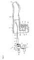
- Fig. 7 is a cross-sectional view of the in-the-ear hearing aid fitted in place and
- Fig. 8 is a conceptual illustration of the in-the-ear hearing aid fitted in place.
- FIG. 1 though 3 A first embodiment of a hearing device according to the present invention is shown in Figs. 1 though 3.
- An in-the-ear hearing aid 3 is composed of a contact vibrator 1 for converting an electric signal to a mechanical signal and transmitting the mechanical signal to an eardrum, a shell 2 for housing the contact vibrator 1 and other components, and the like.
- the contact vibrator 1 is composed of a vibrator 5 for converting an electric signal to a mechanical vibration, a vibration transmitting section 6 for transmitting the mechanical vibration generated by the vibrator 5 to the eardrum, a plug 7 for transmitting the electric signal to the vibrator 5, and the like.
- a multilayer piezoelectric element (for example, made by NEC TOKIN Corporation) is used as the contact vibrator 5, but an electromechanical converter such as a conductivity type and a magneto-striction type is also available.
- the vibration transmitting section 6 is fixedly secured to one end of the vibrator 5 through a reinforcing member 8 and a connecting section 9 is fixedly secured to the other end of the vibrator 5.
- the connecting section 9 is provided with a through-hole 9a into which a guide member 10 for guiding the moving direction of the vibrator 5 is pressed and a through-hole 9b into which a later described stopper is firmly fitted.
- a mechanical impedance relative to the direction of action of force in the actual use condition be much larger than the mechanical impedance of the eardrum.
- a rod with an outer diameter of 0.6 mm in SUS 304 is used. It is desirable that the vibration transmitting section 6 be made straight to maximize the mechanical impedance, but there are some cases where the vibration transmitting section 6 can not be made straight for some users because there are two curves in an external ear canal. In such a case, the vibration transmitting section 6 can be properly bent to suit the individual.
- a tip 11 Secured to an end of the vibration transmitting section 6 is a tip 11 adapted to come into direct contact with the eardrum and the like to sufficiently transmit the mechanical vibration.
- the tip 11 can be coated with a harmless oil (such as olive oil) and the like to stabilize a contact condition with the eardrum.
- the tip 11 can be made of a silicone and the like.
- the plug 7 forms a connector together with a receptacle 12 secured to the inside of the shell 2.
- the plug 7 is electrically connected to the receptacle 12 and functions as a member for positioning the contact vibrator 1 relative to the receptacle 12.
- An electrode 7a is secured to the plug 7.
- the vibrator 5 and the plug 7 are electrically connected by an input terminal 5a of the vibrator 5 and a lead wire 13.
- the electrode 7a of the plug 7 and an electrode (not shown) of the receptacle 12 are caused to come into contact to be electrically connected.
- An arm 14 is integrally formed with the plug 7 and is provided with a female screw hole 14a into which a male screw section 15a of a screw 15 is screwed and a through-hole 14b into which the guide member 10 is slidably fitted.
- the plug 7 is also provided with a knob 16 to provide the user with smooth access to the receptacle 12.
- the arm 14 controls the movement of the screw 15 and the guide member 10.
- Reference numeral 17 is a magnet embedded in a tip of the plug 7.
- the magnet 17 serves to hold the contact vibrator 1 with a moderate suction force between the magnet 17 and a magnetic body 18 embedded in the receptacle 12 so that the contact vibrator 1 does not fall off the receptacle 12 as a result of an external force such as a vibration which acts during the fitting operation.
- the magnet 17 is also provided in such a manner that the contact vibrator 1 can be easily pulled out by grasping the knob 16.
- the screw 15 is provided, as shown in Fig. 4 , to adjust the position of the vibrator 5 and the vibration transmitting section 6 in the longitudinal direction.
- the screw 15 is provided with the stopper 15b described above on one end and a knob 15c on the other end and forms a position adjusting means for the contact vibrator 1 together with a female screw hole 14a of a small diameter formed on the arm 14 and the connecting section 9 into which the stopper 15b is fitted.
- the knob 15c By rotating the knob 15c to move the screw 15 back and forth, the connecting section 9 is caused to move, thereby being capable of adjusting the position of the tip 11 of the vibrator 5 secured to the connecting section 9.
- the guide member 10 When positioning of the vibrator 5 is adjusted by the screw 15, the guide member 10 serves to prevent the vibrator 5 from rotating and to accurately guide the moving direction of the vibrator 5.
- the stopper 15b is adapted to engage with a through-hole 9b consisting of a small diameter hole and a large diameter hole to prevent the screw 15 from pulling out from the connecting section 9.
- the knob 15c is provided to allow the user to easily rotate the screw 15 with his fingers.
- Reference numeral 19 is a spring coiled around the screw 15 and is compressively inserted between the connecting section 9 and a large diameter hole 14c which communicates with the female screw hole 14a of the arm 14.
- the shell 2 is made based on an ear mold which was taken from the user in advance.
- the shell 2 serves as a standard whereby the tip 11 of the contact vibrator 1 is positioned in substantially the same location relative to the eardrum for each fitting operation to come into contact with the eardrum.
- the shell 2 which is normally provided with a portion of a cavum conchae (cavity of the concha) and a concha of ear is made although it depends upon the size of an ear of the user.
- An entire hearing aid is housed in the shell 2.
- the receptacle 12 is positioned by the shell 2 in such a manner that the tip of the contact vibrator 1 comes into contact with the vicinity of an umbo of the eardrum when a hearing aid is made for the user and is secured to the shell 2 using an adhesive agent 20 or the like.
- the receptacle 12 is provided with a recessed section 12a and a groove section 12b into which the plug 7 is fitted.
- the receptacle 12 is embedded with an electrode 12c for electric connection and a magnetic body 18 for attracting the plug 7 with a moderate force.
- a microphone 21 converts a sound input from a sound intake 22 to an electric signal.
- An electric circuit section 23 amplifies or signal-processes the output from the microphone 21 and outputs the electric signal for driving the contact vibrator 1. The electric signal is then transmitted to the vibrator 5 through the electrode 12c of the receptacle 12, the electrode 7a of the plug 7, the lead wire 13, the input terminal 5 a and the like.
- a battery 24 provides the microphone 21 and the electric circuit section 23 with electric power and a power switch 25 turns the power supply on or off to the microphone 21 and the electric circuit section 23.
- a face plate 26 is a plate shape plastic casing into which the sound intake 22, the microphone 21, the electric circuit section 23, the battery 24, the power switch 25 and the like are incorporated and is joined to part of an edge section of the shell 2.
- the user is required to fit the shell 2 into his ear. Since the shell 2 can not be fitted into the ear simply by pushing it to the inside of an external ear canal 30, it is advisable that the shell 2 be fitted into the ear by twisting it back and forth with the fingers in the range of about a half-turn. In the case where the shell 2 is not properly fitted into place, since part of the shell 2 strongly pushes the skin, the user recognizes this fact by feel. When the shell 2 is properly fitted into place, the shell 2 becomes stable and the user does not feel uncomfortable.
- the tip 11 of the contact vibrator 1 is slowly inserted into the external ear canal 30 through the shell 2, by grasping the knob 16 of the contact vibrator 1 with the fingers, wherein the plug 7 is caused to engage with the receptacle 12 and the arm 14 of the plug 7 is caused to engage with the groove 12b of the receptacle 12 for insertion.
- This operation can be easily performed once the user gets used to it. Since the receptacle 12 is secured to the shell 2 after adjusting its position in advance, when the plug 7 is fitted into the receptacle 12, as shown in Fig.
- Fig. 8 shows a condition in which the in-the-ear hearing aid 3 is fitted in place.
- Reference numeral 32 is an auricle of ear.
- the electric signal which has properly amplified and signal-processed the sound input to the microphone 21 is input to the vibrator 5 through the receptacle 12, the plug 7 and the like, whereby the vibrator 5 vibrates accordingly.
- This vibration is transmitted to the eardrum 31 through the vibration transmitting section 6 and the tip 11 and thus, the eardrum is caused to vibrate to transmit the acoustic energy to the acoustic sense.
- the acoustic energy can be transmitted to the acoustic sense through a vestibular window and the cochlea by causing the tip 11 of the contact vibrator 1 to contact a part within the ear ossicle such as the stirrup bone.
- the power switch 25 is turned on and the user himself rotates the knob 15c with his fingers to a condition in which an audio output is generated. In this manner, a favorable carrying power can be obtained by adjusting the position of the tip 11 while confirming the degree of the carrying power. However, if a favorable carrying power still cannot be obtained even by this adjustment, the user is required to pull out the plug 7 by holding the knob 16 with his fingers, wherein fitting of the in-the-ear hearing aid can be discontinued at once.
- Fig. 9 is a conceptual illustration of a behind-the-ear hearing aid 40, to which the present invention is applied, fitted in place.
- a microphone, an electric circuit section, a battery, a power switch and the like are incorporated in an ear hook casing 41.
- An electric output is conducted by a cord 43 passing through a hook 42 and the like, and a connector 44 at the tip of the cord 43 is fitted into another connector (making a pair) secured to a shell 45, wherein the output from the connector is electrically connected to an electrode of a receptacle secured to a predetermined area of the shell 45 by a lead wire.
- a user is required to fit the connector 44 into a connector secured to the inside of the shell 45.
- the user After electrically connecting the ear hook casing 41 to the shell 45, the user fits the shell 45 into the correct location in his ear and hooks the ear hook casing 41 behind the ear.
- a subsequent method of fitting of the contact vibrator 1 into the shell 45 is the same as for the in-the-ear hearing aid 3.
- Fig. 10 is a side view of a second embodiment of a contact vibrator according to the present invention in which a position adjusting means of a vibration transmitting section 56 in the longitudinal direction is not provided.
- a vibrator 55 is directly secured to an arm 64, which is integrally formed with a plug 57, through a connecting section 59.
- Reference numeral 57a is an electrode
- 58 is a reinforcing member
- 59a is an input terminal
- 61 is a tip
- 63 is a lead wire
- 66 is a knob, respectively.
- a structure is shown by which the contact vibrator 1 is provided with the plug 7 and the shell 2 is provided with the receptacle 12.
- an object of the present invention is to establish a relative positional relationship between the contact vibrator 1 and the shell 2 when the plug 7 is fitted into the receptacle 12
- a structure in which the contact vibration 1 is provided with the receptacle 12 and the shell 2 is provided with the plug 7 is also available.
- the contact vibrator 1 can be connected to the shell 2 and the like with a string or an elastic cord for drop prevention.
- the lead wire 13 for electric connection between the input terminal 5a of the vibrator 5 and the electrode 7a of the plug 7 can be secured to the arm 14 and the like so as not to hinder the operation of the contact vibrator 1.
- a flexible print-circuit board can be used in place of the lead wire 13, or part of the lead wire 13 can also be replaced with the flexible print-circuit board.
- the spring 19 is not provided in the position adjusting means, but a screw 85 can be rotated with a knob 85c.
- a male screw section 85a of the screw 85 is caused to engage a female threaded hole 79a of a connecting section 79 to move the connecting section 79 back and forth, thereby positioning the vibrator 5 which is secured to the connecting section 79.
- Reference numeral 85b is a stopper.
- Reference numeral 86 is a falling-off prevention member adapted to engage a through hole 74a consisting of a small diameter hole and a large diameter hole formed on an arm 74. The falling-off prevention member 86 is integrally formed with the screw 85.
- An in-the-ear hearing aid 91 is composed of a contact vibrator 90 for converting an electric signal to a mechanical vibration and transmitting the mechanical vibration to an eardrum, a shell 2 for housing the contact vibrator 90 and other components, and the like.
- the contact vibrator 90 is composed of a column-shaped vibrator 5 for converting an electric signal to a mechanical vibration, a bar-shaped vibration transmitting section 6 for transmitting the mechanical vibration generated by the vibrator 5 to the eardrum, a vibrator side mounting section 92 for positioning the vibrator 5 in the shell 2 and transmitting the electric signal to the vibrator 5, and the like.
- the vibrator 5, the vibration transmitting section 6, and the tip 11 secured to an end of the vibration transmitting section 6 have the same configuration as in the first embodiment of the hearing device.
- the vibration transmitting section 6 is fixedly secured to one end of the vibrator 5 and a connecting member 93 of an insulating body is fixedly secured to the other end thereof.
- the connecting member 93 is sandwiched between a pair of electrodes 94a and 94b of a magnetic body.
- the electrodes 94a and 94b are provided with a substantially horseshoe shape guide member 95.
- a vibrator side mounting section 92 is composed of the connecting member 93, electrodes 94a and 94b, the guide member 95, and the like.
- the vibrator side mounting section 92 forms an electric connector together with a rail section 96 secured to the inside of the shell 2 and acts as a mounting position adjusting member of the contact vibrator 90 relative to the rail section 96.
- Reference numeral 92a is a stopper for the rail section 96 for positioning the contact vibrator 90.
- the electrodes 94a, 94b are plated with gold.
- the rail section 96 is composed of a plate shape magnet 97 secured to the inside of the shell 2, a flexible print-circuit board 98 fixedly secured to the upper surface of the magnet 97, and a pair of rail shape electrodes 99a and 99b disposed on the flexible print-circuit board 98 to face the electrodes 94a, 94b. Since the electrodes 94a, 94b are connected to input terminals 5a and 5b of the vibrator 5 by lead wires 13a and 13b, the vibrator 5 and electrodes 94a, 94b are electrically connected.
- the electrodes 94a, 94b of the vibrator side mounting section 92 and electrodes 99a, 99b of the rail section 96 are caused to come into contact with a moderate magnetic force of the magnet 97, to be electrically connected.
- the vibrator 5 is electrically connected to the electric circuit section 23 and the like through the electrodes 94a, 94b, 99a and 99b, the flexible print-circuit board 98 and the like.
- the electrodes 94a, 94b of the vibrator side mounting section 92 are provided to slide smoothly in a contacting condition with the electrodes 99a, 99b of the rail section 96 with a moderate magnetic force of the magnet 97 and thus, the contact vibrator 90 can be set in a desired position relative to the shell 2.
- the moderate magnetic force of the magnet 97 provides a sufficient force to hold the contact vibrator 90 to a degree so that the contact vibrator 90 does not depart from the rail section 96 by an external force such as vibration acting during the fitting operation and the user can demount the contact vibrator 90 without difficulty.
- the rail section 96 is positioned within the shell 2 and secured thereto by an adhesive agent 20 and the like in such a manner that, at the time when the user's hearing aid is constructed, the tip 11 secured to an end of the contact vibrator 90 comes into contact with the vicinity of the umbo of the eardrum in a condition in which an end section 96a of the rail section 96 is caused to touch a stopper 92a of the vibrator side mounting section 92 to allow the vibrator side mounting section 92 to engage with the rail section 96.
- the contact vibrator 90 be fitted in the shell 2 in such a manner that the vibrator side mounting section 92 engages with the rail section 96 to allow the end section 96a of the rail section 96 to touch the stopper 92a.
- a magnetic body is secured to a pullout means 95a of the guide member 95 so that the contact vibrator 90 can be pulled out by attracting the pullout means 95a using a magnet. It is easier to pull out the contact vibrator 90 if a linear member for pullout (not shown) is attached to the pullout means 95a in place of the magnetic body.
- a linear member for pullout (not shown) is attached to the pullout means 95a in place of the magnetic body.
- Other configurations are the same as in the first embodiment of the hearing device.
- the user is required to fit the shell 2 into his ear. Since the shell 2 cannot be properly fitted simply by pushing the shell 2 to the inside of the external ear canal 30, it is advisable that the shell 2 be twisted back and forth in the range of about half turn. In the case where the shell 2 cannot be fitted in place, since part of the shell 2 strongly pushes the skin, the user recognizes by the feel that the shell 2 has not been fitted in place. Once the shell 2 is fitted in place, the shell 2 reaches a stable condition and the user does not feel uncomfortable.
- the tip 11 of the contact vibrator 90 is slowly inserted into the external ear canal 30 through the shell 2, grasping the vibrator side mounting section 92 of the contact vibrator 90 with the fingers. After allowing the vibrator side mounting section 92 to engage with the rail section 96 and fitting the rail section 96 into the guide member 95, the vibrator side mounting section 92 is caused to slide until the end section 96a of the rail section 96 touches the stopper 92a. This operation can be easily performed, once the user gets used to it.
- the rail section 96 Since the rail section 96 is secured to the shell 2 after adjusting the location in advance, when the end section 96a of the rail section 96 touches the stopper 92, as shown in Fig. 6 , the tip 11 of the contact vibrator 90 comes into contact with the vicinity of the umbo 31 a which is a predetermined location of the eardrum 31.
- the acoustic energy can be transmitted to the seat of the acoustic sense through a vestibular window and a cochlea by allowing the tip 11 of the contact vibrator 90 to contact a part within the ear ossicle such the a stirrup bone.
- the in-the-ear hearing aid 3, 91 and the behind-the-ear hearing aid 40 to which the contact vibrator according to the present invention and the hearing device using the same is applied is described, but the present invention can also be applied to an audio hearing device such as a headset.
- a contact vibrator can be detachably mounted on a device using the contact vibrator so that a vibration transmitting section comes in contact with an eardrum.
- a vibrator side mounting section provided on the contact vibrator is mounted on a body side mounting section which is secured to a shell, positioning of the tip of the vibration transmitting section relative to the eardrum and the like is properly made and as a result, a hearing device which is easily handled by the user can be provided.
- the fourth aspect of the present invention if a plug provided on the contact vibrator is fitted into a receptacle secured to the shell, positioning of the tip of the vibration transmitting section relative to the eardrum and the like can be properly made and as a result, a hearing device which is easily handled by the user can be provided.
- the vibrator side mounting section can be maintained in place by a magnetic force.
- an electrode made of a magnetic body of a mounting member provided on the contact vibrator is slidably mounted on a rail shape electrode, positioning of the tip of the vibration transmitting section relative to the eardrum can be properly secured. Further, since the electrode made of a magnetic body is supported with a moderate magnetic force by an electrode provided on a body mounting member, mounting and demounting of the contact vibrator relative to the shell can be readily conducted.
- a plug or a vibrator side mounting section provided on a contact vibrator is caused to engage with a receptacle or a rail section secured to a shell, positioning of a tip of a vibration transmitting section relative to an eardrum and the like can be properly conducted and as a resuit, it is possible to provide a hearing device such as an in-the-ear hearing aid and a behind-the-ear hearing aid which are easily handled by a user.
Landscapes
- Health & Medical Sciences (AREA)
- General Health & Medical Sciences (AREA)
- Otolaryngology (AREA)
- Neurosurgery (AREA)
- Physics & Mathematics (AREA)
- Engineering & Computer Science (AREA)
- Acoustics & Sound (AREA)
- Signal Processing (AREA)
- Telephone Set Structure (AREA)
- Headphones And Earphones (AREA)
Abstract
Description
- The present invention relates to a contact vibrator for converting an acoustic signal to a mechanical vibration and directly transmitting the mechanical vibration to a hearing organ such as an eardrum, and to a hearing device using the contact vibrator.
- In a conventional air-conduction hearing aid, a sound captured by a microphone is signal-processed (e.g., amplification or filter out) depending upon the degree of a user's carrying power and is output from an earphone. Since the output is the same physical quantity as an input, in other words, a sound spread in the air, feedback is easily generated. On the contrary, in a conventional bone-conduction hearing aid, it is difficult to generate feedback because the output is a mechanical vibration. However, since a vibration is imparted to lymph fluid in an inner ear through the skull and an acoustic signal is transmitted to the acoustic sense, there is a drawback in which efficiency is less than the air-conduction hearing aid which transmits the vibration to the lymph fluid of the inner ear through a middle ear and this takes up much space.
- Consequently, it is more efficient if the mechanical vibration of the output is directly imparted to an eardrum, not through the skull as seen in the bone-conduction hearing aid. From this point of view, a hearing aid is known in which a converter adapted to output the input acoustic signal in the form of a mechanical vibration is used and an output end of the converter and the eardrum are connected at a vibration transmitting section to directly transmit the vibration to the eardrum (for example, refer to Patent Document 1).
Patent Document 1:US Patent No. 6137889 - However, in the invention disclosed in
Patent Document 1, the mechanical vibration output end of the converter is mechanically and directly connected to the delicate eardrum and as a result, it is necessary to provide a mechanism which does not impart an excessive force to the eardrum. Further, in this invention, it is not easy for a user to wear the hearing aid so that the vibration transmitting section comes in contact with the eardrum in a proper condition. In such a hearing aid, since it is necessary to do maintenance such as a battery change, periodical mounting and demounting is imperative. In such a case, there is a vexatious complication that the wearer must ask an expert such as an otorhinolaryngologist to do the maintenance. - It is therefore an object of the present invention to solve the problems seen in the prior art and to provide for the wearer a contact vibrator which is readily detachable and a hearing device using the same.
- In order to attain this object, according to a first aspect of the present invention, a contact vibrator is provided, which comprises a vibrator for converting an electric signal to a mechanical vibration, a vibration transmitting section for transmitting the mechanical vibration from the vibrator to an eardrum, and a vibrator side mounting section having an electrode and adapted to transmit the electric signal to the vibrator.
- According to a second aspect of the present invention, the contact vibrator of the first aspect is provided, in which a position adjusting means is provided to adjust the position of the vibration transmitting section in the longitudinal direction by adjusting the distance between the vibrator and the vibrator side mounting section.
- According to a third aspect of the present invention, a hearing device is provided, which comprises a contact vibrator of the first aspect or the second aspect, a microphone for converting an acoustic signal to an electric signal, an electric circuit section for signal-processing the electric signal converted by the microphone, a body side mounting section which has an electrode to be electrically connected to the electric circuit section and on which the vibrator side mounting section is detachably mounted and which comes into contact with an electrode of the vibrator side mounting section to be electrically connected, and a body section provided with a shell to which the body side mounting section is secured and which is made to adapt to the shape of an external ear canal of a user, wherein, when the vibrator side mounting section is mounted on the body side mounting section, a tip of the vibration transmitting section comes into contact with an eardrum or an ear ossicle.
- According to a fourth aspect of the present invention, the hearing device of the third aspect is provided, in which the body side mounting section is a receptacle and the vibrator side mounting section is a plug.
- According to a fifth aspect of the present invention, the hearing device of the third aspect is provided, in which the body side mounting section is provided with a magnet while the vibrator side mounting section is provided with a magnetic body and is connected to the body side mounting section by means of magnetic force.
- According to a sixth aspect of the present invention, the hearing device of the third aspect is provided, in which the body side mounting section is a rail section provided with an electrode on a plate shape magnet and the vibrator side mounting section is provided with an electrode made of a magnetic body, wherein the rail section and the vibrator side mounting section are provided to cause mutual electrodes to come into close contact with each other by means of magnetic force, and the vibrator side mounting section is slidably mounted on the body side mounting section.
- The above and other objects, features and advantages of the present invention will become more apparent from the following description when taken in conjunction with the accompanying drawings.
-
Fig. 1 is a front view of an in-the-ear hearing aid to which a first embodiment of a hearing device according to the present invention is applied; -
Fig. 2 is a cross-sectional view taken along line A-A ofFig. 1 ; -
Fig. 3 is a partially exploded cross-sectional view of the in-the-ear hearing aid; -
Fig. 4 is an enlarged cross-sectional view of a position adjusting means; -
Fig. 5 is an explanatory view of the in-the-ear hearing aid (shell) at the stage of fitting; -
Fig. 6 is an explanatory view of the in-the-ear hearing aid (contact vibrator) at the stage of fitting; -
Fig. 7 is a cross-sectional view of the in-the-ear hearing aid fitted in place; -
Fig. 8 is a conceptual illustration of the in-the-ear hearing aid fitted in place; -
Fig. 9 is a conceptual illustration of a behind-the-ear hearing aid fitted in place to which the present invention is applied; -
Fig. 10 is a side view of a second embodiment of a contact vibrator according to the present invention; -
Fig. 11 is an enlarged cross-sectional view of another embodiment of the position adjusting means; -
Fig. 12 is a third embodiment of the contact vibrator according to the present invention, in which (a) is a plan view, (b) is a side view of a partial cross-section, and (c) is a rear view; -
Fig. 13 is a side view of a partial cross-section of an in-the-ear hearing aid to which a second embodiment of the hearing device according to the present invention is applied; -
Fig. 14 is an enlarged cross-sectional view taken along a line B-B ofFig. 13 ; -
Fig. 15 is an explanatory view of the in-the-ear hearing aid at the stage of fitting to which the second embodiment of the hearing device according to the present invention is applied; and -
Fig. 16 is a side view of a partial cross-section of the in-the-ear hearing aid fitted in place. - A preferred embodiment of the present invention will now be described with reference to the accompanying drawings.
Fig. 1 is a front view of an in-the-ear hearing aid to which a first embodiment of a hearing device according to the present invention is applied.Fig. 2 is a cross-sectional view taken along line A-A ofFig. 1 .Fig. 3 is a partially exploded cross-sectional view of the in-the-ear hearing aid.Fig. 4 is an enlarged cross-sectional view of a position adjusting means.Figs. 5 and6 are explanatory views of the in-the-ear hearing aid in the process of fitting.Fig. 7 is a cross-sectional view of the in-the-ear hearing aid fitted in place andFig. 8 is a conceptual illustration of the in-the-ear hearing aid fitted in place. - A first embodiment of a hearing device according to the present invention is shown in
Figs. 1 though 3. An in-the-ear hearing aid 3 is composed of acontact vibrator 1 for converting an electric signal to a mechanical signal and transmitting the mechanical signal to an eardrum, ashell 2 for housing thecontact vibrator 1 and other components, and the like. Thecontact vibrator 1 is composed of avibrator 5 for converting an electric signal to a mechanical vibration, a vibration transmittingsection 6 for transmitting the mechanical vibration generated by thevibrator 5 to the eardrum, aplug 7 for transmitting the electric signal to thevibrator 5, and the like. - A multilayer piezoelectric element (for example, made by NEC TOKIN Corporation) is used as the
contact vibrator 5, but an electromechanical converter such as a conductivity type and a magneto-striction type is also available. The vibration transmittingsection 6 is fixedly secured to one end of thevibrator 5 through a reinforcing member 8 and a connectingsection 9 is fixedly secured to the other end of thevibrator 5. The connectingsection 9 is provided with a through-hole 9a into which aguide member 10 for guiding the moving direction of thevibrator 5 is pressed and a through-hole 9b into which a later described stopper is firmly fitted. - Referring to the vibration transmitting
section 6, it is desirable that a mechanical impedance relative to the direction of action of force in the actual use condition be much larger than the mechanical impedance of the eardrum. In the present embodiment, a rod with an outer diameter of 0.6 mm in SUS 304 is used. It is desirable that the vibration transmittingsection 6 be made straight to maximize the mechanical impedance, but there are some cases where the vibration transmittingsection 6 can not be made straight for some users because there are two curves in an external ear canal. In such a case, the vibration transmittingsection 6 can be properly bent to suit the individual. - Secured to an end of the vibration transmitting
section 6 is atip 11 adapted to come into direct contact with the eardrum and the like to sufficiently transmit the mechanical vibration. Thetip 11 can be coated with a harmless oil (such as olive oil) and the like to stabilize a contact condition with the eardrum. In this case, thetip 11 can be made of a silicone and the like. In the case where thetip 11 is not coated with the oil and like, it is desirable that the tip be made of material such as Teflon (Registered Trademark) which does not stick to the eardrum. - The
plug 7 forms a connector together with areceptacle 12 secured to the inside of theshell 2. Theplug 7 is electrically connected to thereceptacle 12 and functions as a member for positioning thecontact vibrator 1 relative to thereceptacle 12. Anelectrode 7a is secured to theplug 7. Thevibrator 5 and theplug 7 are electrically connected by aninput terminal 5a of thevibrator 5 and alead wire 13. When theplug 7 is fitted into thereceptacle 12, theelectrode 7a of theplug 7 and an electrode (not shown) of thereceptacle 12 are caused to come into contact to be electrically connected. - An
arm 14 is integrally formed with theplug 7 and is provided with afemale screw hole 14a into which amale screw section 15a of ascrew 15 is screwed and a through-hole 14b into which theguide member 10 is slidably fitted. Theplug 7 is also provided with aknob 16 to provide the user with smooth access to thereceptacle 12. Thearm 14 controls the movement of thescrew 15 and theguide member 10. When theplug 7 is inserted into thereceptacle 12, part of thearm 14 is fitted into agroove section 12b of thereceptacle 12 without play to prevent theplug 7 from being rotated around its axis. -
Reference numeral 17 is a magnet embedded in a tip of theplug 7. When theplug 7 is fitted into thereceptacle 12, themagnet 17 serves to hold thecontact vibrator 1 with a moderate suction force between themagnet 17 and amagnetic body 18 embedded in thereceptacle 12 so that thecontact vibrator 1 does not fall off thereceptacle 12 as a result of an external force such as a vibration which acts during the fitting operation. When the user removes thecontact vibrator 1 from thereceptacle 12, themagnet 17 is also provided in such a manner that thecontact vibrator 1 can be easily pulled out by grasping theknob 16. - The
screw 15 is provided, as shown inFig. 4 , to adjust the position of thevibrator 5 and thevibration transmitting section 6 in the longitudinal direction. Thescrew 15 is provided with thestopper 15b described above on one end and aknob 15c on the other end and forms a position adjusting means for thecontact vibrator 1 together with afemale screw hole 14a of a small diameter formed on thearm 14 and the connectingsection 9 into which thestopper 15b is fitted. By rotating theknob 15c to move thescrew 15 back and forth, the connectingsection 9 is caused to move, thereby being capable of adjusting the position of thetip 11 of thevibrator 5 secured to the connectingsection 9. - When positioning of the
vibrator 5 is adjusted by thescrew 15, theguide member 10 serves to prevent thevibrator 5 from rotating and to accurately guide the moving direction of thevibrator 5. Thestopper 15b is adapted to engage with a through-hole 9b consisting of a small diameter hole and a large diameter hole to prevent thescrew 15 from pulling out from the connectingsection 9. Theknob 15c is provided to allow the user to easily rotate thescrew 15 with his fingers.Reference numeral 19 is a spring coiled around thescrew 15 and is compressively inserted between the connectingsection 9 and alarge diameter hole 14c which communicates with thefemale screw hole 14a of thearm 14. - The
shell 2 is made based on an ear mold which was taken from the user in advance. Theshell 2 serves as a standard whereby thetip 11 of thecontact vibrator 1 is positioned in substantially the same location relative to the eardrum for each fitting operation to come into contact with the eardrum. Theshell 2 which is normally provided with a portion of a cavum conchae (cavity of the concha) and a concha of ear is made although it depends upon the size of an ear of the user. An entire hearing aid is housed in theshell 2. - The
receptacle 12 is positioned by theshell 2 in such a manner that the tip of thecontact vibrator 1 comes into contact with the vicinity of an umbo of the eardrum when a hearing aid is made for the user and is secured to theshell 2 using anadhesive agent 20 or the like. Thereceptacle 12 is provided with a recessedsection 12a and agroove section 12b into which theplug 7 is fitted. Thereceptacle 12 is embedded with anelectrode 12c for electric connection and amagnetic body 18 for attracting theplug 7 with a moderate force. - A
microphone 21 converts a sound input from asound intake 22 to an electric signal. Anelectric circuit section 23 amplifies or signal-processes the output from themicrophone 21 and outputs the electric signal for driving thecontact vibrator 1. The electric signal is then transmitted to thevibrator 5 through theelectrode 12c of thereceptacle 12, theelectrode 7a of theplug 7, thelead wire 13, theinput terminal 5 a and the like. Abattery 24 provides themicrophone 21 and theelectric circuit section 23 with electric power and apower switch 25 turns the power supply on or off to themicrophone 21 and theelectric circuit section 23. Aface plate 26 is a plate shape plastic casing into which thesound intake 22, themicrophone 21, theelectric circuit section 23, thebattery 24, thepower switch 25 and the like are incorporated and is joined to part of an edge section of theshell 2. - Operation of the in-the-
ear hearing aid 3 to which the first embodiment of the hearing device according to the present invention is applied will now be described. First, as shown inFig. 5 , the user is required to fit theshell 2 into his ear. Since theshell 2 can not be fitted into the ear simply by pushing it to the inside of anexternal ear canal 30, it is advisable that theshell 2 be fitted into the ear by twisting it back and forth with the fingers in the range of about a half-turn. In the case where theshell 2 is not properly fitted into place, since part of theshell 2 strongly pushes the skin, the user recognizes this fact by feel. When theshell 2 is properly fitted into place, theshell 2 becomes stable and the user does not feel uncomfortable. - Next, after confirming that the
shell 2 has been fitted in place, as shown inFig. 6 , thetip 11 of thecontact vibrator 1 is slowly inserted into theexternal ear canal 30 through theshell 2, by grasping theknob 16 of thecontact vibrator 1 with the fingers, wherein theplug 7 is caused to engage with thereceptacle 12 and thearm 14 of theplug 7 is caused to engage with thegroove 12b of thereceptacle 12 for insertion. This operation can be easily performed once the user gets used to it. Since thereceptacle 12 is secured to theshell 2 after adjusting its position in advance, when theplug 7 is fitted into thereceptacle 12, as shown inFig. 7 , thetip 11 of thecontact vibrator 1 comes into contact with the vicinity of theumbo 31 1a which is a predetermined location of theeardrum 31.Fig. 8 shows a condition in which the in-the-ear hearing aid 3 is fitted in place.Reference numeral 32 is an auricle of ear. - Next, when the
power switch 25 is turned on, the electric signal which has properly amplified and signal-processed the sound input to themicrophone 21 is input to thevibrator 5 through thereceptacle 12, theplug 7 and the like, whereby thevibrator 5 vibrates accordingly. This vibration is transmitted to theeardrum 31 through thevibration transmitting section 6 and thetip 11 and thus, the eardrum is caused to vibrate to transmit the acoustic energy to the acoustic sense. In the case of a person without aneardrum 31 or a person whoseeardrum 31 adheres to a wall of the middle ear cavity, the acoustic energy can be transmitted to the acoustic sense through a vestibular window and the cochlea by causing thetip 11 of thecontact vibrator 1 to contact a part within the ear ossicle such as the stirrup bone. - In the case where contact between the
tip 11 of thecontact vibrator 1 and theeardrum 31 is undesirable when theplug 7 of thecontact vibrator 1 is fitted into thereceptacle 12, thepower switch 25 is turned on and the user himself rotates theknob 15c with his fingers to a condition in which an audio output is generated. In this manner, a favorable carrying power can be obtained by adjusting the position of thetip 11 while confirming the degree of the carrying power. However, if a favorable carrying power still cannot be obtained even by this adjustment, the user is required to pull out theplug 7 by holding theknob 16 with his fingers, wherein fitting of the in-the-ear hearing aid can be discontinued at once. -
Fig. 9 is a conceptual illustration of a behind-the-ear hearing aid 40, to which the present invention is applied, fitted in place. In this case, a microphone, an electric circuit section, a battery, a power switch and the like are incorporated in anear hook casing 41. An electric output is conducted by acord 43 passing through ahook 42 and the like, and aconnector 44 at the tip of thecord 43 is fitted into another connector (making a pair) secured to ashell 45, wherein the output from the connector is electrically connected to an electrode of a receptacle secured to a predetermined area of theshell 45 by a lead wire. A user is required to fit theconnector 44 into a connector secured to the inside of theshell 45. After electrically connecting the ear hook casing 41 to theshell 45, the user fits theshell 45 into the correct location in his ear and hooks the ear hook casing 41 behind the ear. A subsequent method of fitting of thecontact vibrator 1 into theshell 45 is the same as for the in-the-ear hearing aid 3. -
Fig. 10 is a side view of a second embodiment of a contact vibrator according to the present invention in which a position adjusting means of avibration transmitting section 56 in the longitudinal direction is not provided. Avibrator 55 is directly secured to anarm 64, which is integrally formed with aplug 57, through a connectingsection 59.Reference numeral 57a is an electrode, 58 is a reinforcing member, 59a is an input terminal, 61 is a tip, 63 is a lead wire, and 66 is a knob, respectively. - In the embodiment of the present invention, a structure is shown by which the
contact vibrator 1 is provided with theplug 7 and theshell 2 is provided with thereceptacle 12. However, since an object of the present invention is to establish a relative positional relationship between thecontact vibrator 1 and theshell 2 when theplug 7 is fitted into thereceptacle 12, a structure in which thecontact vibration 1 is provided with thereceptacle 12 and theshell 2 is provided with theplug 7 is also available. - Since it is anticipated that the
contact vibrator 1 could be accidentally dropped, thecontact vibrator 1 can be connected to theshell 2 and the like with a string or an elastic cord for drop prevention. In thecontact vibrator 1, thelead wire 13 for electric connection between theinput terminal 5a of thevibrator 5 and theelectrode 7a of theplug 7 can be secured to thearm 14 and the like so as not to hinder the operation of thecontact vibrator 1. A flexible print-circuit board can be used in place of thelead wire 13, or part of thelead wire 13 can also be replaced with the flexible print-circuit board. - Referring to
Fig. 11 , thespring 19 is not provided in the position adjusting means, but ascrew 85 can be rotated with aknob 85c. In this case, it is necessary to provide a structure in which the position adjusting means does not move back and forth, wherein amale screw section 85a of thescrew 85 is caused to engage a female threadedhole 79a of a connectingsection 79 to move the connectingsection 79 back and forth, thereby positioning thevibrator 5 which is secured to the connectingsection 79.Reference numeral 85b is a stopper.Reference numeral 86 is a falling-off prevention member adapted to engage a throughhole 74a consisting of a small diameter hole and a large diameter hole formed on anarm 74. The falling-off prevention member 86 is integrally formed with thescrew 85. - Next, a second embodiment of a hearing device according to the present invention is shown in
Figs. 12 through 14 . An in-the-ear hearing aid 91 is composed of acontact vibrator 90 for converting an electric signal to a mechanical vibration and transmitting the mechanical vibration to an eardrum, ashell 2 for housing thecontact vibrator 90 and other components, and the like. Thecontact vibrator 90 is composed of a column-shapedvibrator 5 for converting an electric signal to a mechanical vibration, a bar-shapedvibration transmitting section 6 for transmitting the mechanical vibration generated by thevibrator 5 to the eardrum, a vibratorside mounting section 92 for positioning thevibrator 5 in theshell 2 and transmitting the electric signal to thevibrator 5, and the like. It is to be noted that thevibrator 5, thevibration transmitting section 6, and thetip 11 secured to an end of thevibration transmitting section 6 have the same configuration as in the first embodiment of the hearing device. - The
vibration transmitting section 6 is fixedly secured to one end of thevibrator 5 and a connectingmember 93 of an insulating body is fixedly secured to the other end thereof. The connectingmember 93 is sandwiched between a pair ofelectrodes electrodes shape guide member 95. A vibratorside mounting section 92 is composed of the connectingmember 93,electrodes guide member 95, and the like. The vibratorside mounting section 92 forms an electric connector together with arail section 96 secured to the inside of theshell 2 and acts as a mounting position adjusting member of thecontact vibrator 90 relative to therail section 96.Reference numeral 92a is a stopper for therail section 96 for positioning thecontact vibrator 90. Theelectrodes - The
rail section 96 is composed of aplate shape magnet 97 secured to the inside of theshell 2, a flexible print-circuit board 98 fixedly secured to the upper surface of themagnet 97, and a pair ofrail shape electrodes circuit board 98 to face theelectrodes electrodes terminals vibrator 5 bylead wires vibrator 5 andelectrodes side mounting section 92 engages therail section 96, theelectrodes side mounting section 92 andelectrodes rail section 96 are caused to come into contact with a moderate magnetic force of themagnet 97, to be electrically connected. In this manner, thevibrator 5 is electrically connected to theelectric circuit section 23 and the like through theelectrodes circuit board 98 and the like. - Since the surfaces of the
electrodes electrodes side mounting section 92 are provided to slide smoothly in a contacting condition with theelectrodes rail section 96 with a moderate magnetic force of themagnet 97 and thus, thecontact vibrator 90 can be set in a desired position relative to theshell 2. The moderate magnetic force of themagnet 97 provides a sufficient force to hold thecontact vibrator 90 to a degree so that thecontact vibrator 90 does not depart from therail section 96 by an external force such as vibration acting during the fitting operation and the user can demount thecontact vibrator 90 without difficulty. - The
rail section 96 is positioned within theshell 2 and secured thereto by anadhesive agent 20 and the like in such a manner that, at the time when the user's hearing aid is constructed, thetip 11 secured to an end of thecontact vibrator 90 comes into contact with the vicinity of the umbo of the eardrum in a condition in which anend section 96a of therail section 96 is caused to touch astopper 92a of the vibratorside mounting section 92 to allow the vibratorside mounting section 92 to engage with therail section 96. In this manner, in order to allow thetip 11 to come into contact with the vicinity of the umbo of the eardrum when the in-the-ear hearing aid 91 is fitted, it is advisable that thecontact vibrator 90 be fitted in theshell 2 in such a manner that the vibratorside mounting section 92 engages with therail section 96 to allow theend section 96a of therail section 96 to touch thestopper 92a. - A magnetic body is secured to a pullout means 95a of the
guide member 95 so that thecontact vibrator 90 can be pulled out by attracting the pullout means 95a using a magnet. It is easier to pull out thecontact vibrator 90 if a linear member for pullout (not shown) is attached to the pullout means 95a in place of the magnetic body. Other configurations are the same as in the first embodiment of the hearing device. - Operation of the in-the-
ear hearing aid 91 constructed above to which the second embodiment of the hearing device according to the present invention is applied will now be described. First, the user is required to fit theshell 2 into his ear. Since theshell 2 cannot be properly fitted simply by pushing theshell 2 to the inside of theexternal ear canal 30, it is advisable that theshell 2 be twisted back and forth in the range of about half turn. In the case where theshell 2 cannot be fitted in place, since part of theshell 2 strongly pushes the skin, the user recognizes by the feel that theshell 2 has not been fitted in place. Once theshell 2 is fitted in place, theshell 2 reaches a stable condition and the user does not feel uncomfortable. - Next, after confirming that the
shell 2 has been fitted in the right place, as shown inFig. 15 , thetip 11 of thecontact vibrator 90 is slowly inserted into theexternal ear canal 30 through theshell 2, grasping the vibratorside mounting section 92 of thecontact vibrator 90 with the fingers. After allowing the vibratorside mounting section 92 to engage with therail section 96 and fitting therail section 96 into theguide member 95, the vibratorside mounting section 92 is caused to slide until theend section 96a of therail section 96 touches thestopper 92a. This operation can be easily performed, once the user gets used to it. Since therail section 96 is secured to theshell 2 after adjusting the location in advance, when theend section 96a of therail section 96 touches thestopper 92, as shown inFig. 6 , thetip 11 of thecontact vibrator 90 comes into contact with the vicinity of theumbo 31 a which is a predetermined location of theeardrum 31. - Next, when the power switch is turned on, an electric signal which has properly amplified and signal-processed a sound input to the
microphone 21 is input to thevibrator 5 through therail section 96, the vibratorside mounting section 92 and the like, wherein the vibrator vibrates. This vibration is transmitted to theeardrum 31 through thevibration transmitting section 6 and thetip 11 to cause the eardrum to vibrate, and the acoustic energy is transmitted to the seat of acoustic sense. In the case of a person without aneardrum 31 or a person whoseeardrum 31 adheres to a wall of the middle ear cavity, the acoustic energy can be transmitted to the seat of the acoustic sense through a vestibular window and a cochlea by allowing thetip 11 of thecontact vibrator 90 to contact a part within the ear ossicle such the a stirrup bone. - In the embodiments of the present invention, the in-the-
ear hearing aid ear hearing aid 40 to which the contact vibrator according to the present invention and the hearing device using the same is applied is described, but the present invention can also be applied to an audio hearing device such as a headset. - According to the first aspect of the present invention, a contact vibrator can be detachably mounted on a device using the contact vibrator so that a vibration transmitting section comes in contact with an eardrum.
- According to the second aspect of the present invention, positioning of a tip of the vibration transmitting section can be readily made.
- According to the third aspect of the present invention, if a vibrator side mounting section provided on the contact vibrator is mounted on a body side mounting section which is secured to a shell, positioning of the tip of the vibration transmitting section relative to the eardrum and the like is properly made and as a result, a hearing device which is easily handled by the user can be provided.
- According to the fourth aspect of the present invention, if a plug provided on the contact vibrator is fitted into a receptacle secured to the shell, positioning of the tip of the vibration transmitting section relative to the eardrum and the like can be properly made and as a result, a hearing device which is easily handled by the user can be provided.
- According to the fifth aspect of the present invention, the vibrator side mounting section can be maintained in place by a magnetic force.
- According to the sixth aspect of the present invention, since an electrode made of a magnetic body of a mounting member provided on the contact vibrator is slidably mounted on a rail shape electrode, positioning of the tip of the vibration transmitting section relative to the eardrum can be properly secured. Further, since the electrode made of a magnetic body is supported with a moderate magnetic force by an electrode provided on a body mounting member, mounting and demounting of the contact vibrator relative to the shell can be readily conducted.
- If a plug or a vibrator side mounting section provided on a contact vibrator is caused to engage with a receptacle or a rail section secured to a shell, positioning of a tip of a vibration transmitting section relative to an eardrum and the like can be properly conducted and as a resuit, it is possible to provide a hearing device such as an in-the-ear hearing aid and a behind-the-ear hearing aid which are easily handled by a user.
Claims (6)
- A contact vibrator comprising:a vibrator for converting an electric signal to a mechanical vibration;a vibration transmitting section for transmitting the mechanical vibration from the vibrator to an eardrum; anda vibrator side mounting section having an electrode and adapted to transmit the electric signal to the vibrator.
- The contact vibrator according to claim 1, wherein a position adjusting means is provided to adjust a position of the vibration transmitting section in the longitudinal direction by adjusting the distance between the vibrator and the vibrator side mounting section.
- A hearing device comprising:a contact vibrator according to claim 1 or claim 2;a microphone for converting an acoustic signal to an electric signal;an electric circuit section for signal-processing the electric signal converted by the microphone;a body side mounting section which has an electrode electrically connected to the electric circuit section and on which the vibrator side mounting section is detachably mounted and which comes into contact with an electrode of the vibrator side mounting section to be electrically connected; anda body section provided with a shell to which the body side mounting section is secured and which is made to meet the shape of a user's external ear canal;characterized in that, when the vibrator side mounting section is mounted on the body side mounting section, a tip of the vibration transmitting section contacts an eardrum or an ear ossicle.
- The hearing device according to claim 3, wherein the body side mounting section is a receptacle and the vibrator side mounting section is a plug.
- The hearing device according to claim 3, wherein the body side mounting section is provided with a magnet and the vibrator side mounting section is provided with a magnetic body and is mounted on the body side mounting section by means of a magnetic force.
- The hearing device according to claim 3, wherein the body side mounting section is a rail section provided with an electrode on a plate shape magnet, the vibrator side mounting section is provided with an electrode made of a magnetic body, the rail section and the vibrator side mounting section are provided to cause mutual electrodes to closely contact each other by means of a magnetic force, and the vibrator side mounting section is slidably mounted on the body side mounting section.
Applications Claiming Priority (2)
| Application Number | Priority Date | Filing Date | Title |
|---|---|---|---|
| JP2007052186 | 2007-03-02 | ||
| JP2008039517A JP5113553B2 (en) | 2007-03-02 | 2008-02-21 | Contact-type vibrator and listening device using the same |
Publications (2)
| Publication Number | Publication Date |
|---|---|
| EP1968347A2 true EP1968347A2 (en) | 2008-09-10 |
| EP1968347A3 EP1968347A3 (en) | 2011-11-09 |
Family
ID=39495237
Family Applications (1)
| Application Number | Title | Priority Date | Filing Date |
|---|---|---|---|
| EP08250706A Withdrawn EP1968347A3 (en) | 2007-03-02 | 2008-02-29 | Contact vibrator and hearing device using the same |
Country Status (1)
| Country | Link |
|---|---|
| EP (1) | EP1968347A3 (en) |
Cited By (4)
| Publication number | Priority date | Publication date | Assignee | Title |
|---|---|---|---|---|
| WO2010133704A3 (en) * | 2010-09-27 | 2011-06-30 | Advanced Bionics Ag | Implantable hearing instrument |
| CN106792406A (en) * | 2016-11-30 | 2017-05-31 | 中国矿业大学 | Encourage the fluid coupling actuator of round window membrane |
| WO2020198334A1 (en) * | 2019-03-27 | 2020-10-01 | Earlens Corporation | Direct print chassis and platform for contact hearing system |
| US20240015456A1 (en) * | 2020-08-20 | 2024-01-11 | The Regents Of The University Of California | Direct drive hearing aid stimulation methods |
Citations (4)
| Publication number | Priority date | Publication date | Assignee | Title |
|---|---|---|---|---|
| GB392625A (en) | 1931-02-17 | 1933-05-25 | Anton Von Suchorzynski | Electric hearing apparatus for the deaf |
| DE592422C (en) | 1931-02-17 | 1934-02-08 | Anton Von Suchorzynski | Electric hearing aid for the hearing impaired |
| US6137889A (en) * | 1998-05-27 | 2000-10-24 | Insonus Medical, Inc. | Direct tympanic membrane excitation via vibrationally conductive assembly |
| WO2001050815A1 (en) * | 1999-12-30 | 2001-07-12 | Insonus Medical, Inc. | Direct tympanic drive via a floating filament assembly |
Family Cites Families (2)
| Publication number | Priority date | Publication date | Assignee | Title |
|---|---|---|---|---|
| US3764748A (en) * | 1972-05-19 | 1973-10-09 | J Branch | Implanted hearing aids |
| DE19618961B4 (en) * | 1996-05-10 | 2004-09-16 | Phonak Ag | Device for electromechanical stimulation and testing of the hearing |
-
2008
- 2008-02-29 EP EP08250706A patent/EP1968347A3/en not_active Withdrawn
Patent Citations (5)
| Publication number | Priority date | Publication date | Assignee | Title |
|---|---|---|---|---|
| GB392625A (en) | 1931-02-17 | 1933-05-25 | Anton Von Suchorzynski | Electric hearing apparatus for the deaf |
| DE592422C (en) | 1931-02-17 | 1934-02-08 | Anton Von Suchorzynski | Electric hearing aid for the hearing impaired |
| US6137889A (en) * | 1998-05-27 | 2000-10-24 | Insonus Medical, Inc. | Direct tympanic membrane excitation via vibrationally conductive assembly |
| WO2001050815A1 (en) * | 1999-12-30 | 2001-07-12 | Insonus Medical, Inc. | Direct tympanic drive via a floating filament assembly |
| US6940989B1 (en) * | 1999-12-30 | 2005-09-06 | Insound Medical, Inc. | Direct tympanic drive via a floating filament assembly |
Cited By (7)
| Publication number | Priority date | Publication date | Assignee | Title |
|---|---|---|---|---|
| WO2010133704A3 (en) * | 2010-09-27 | 2011-06-30 | Advanced Bionics Ag | Implantable hearing instrument |
| CN106792406A (en) * | 2016-11-30 | 2017-05-31 | 中国矿业大学 | Encourage the fluid coupling actuator of round window membrane |
| CN106792406B (en) * | 2016-11-30 | 2019-06-18 | 中国矿业大学 | Fluid-coupled actuators that excite round window membranes |
| WO2020198334A1 (en) * | 2019-03-27 | 2020-10-01 | Earlens Corporation | Direct print chassis and platform for contact hearing system |
| US11930325B2 (en) | 2019-03-27 | 2024-03-12 | Earlens Corporation | Direct print chassis for contact hearing system |
| US20240015456A1 (en) * | 2020-08-20 | 2024-01-11 | The Regents Of The University Of California | Direct drive hearing aid stimulation methods |
| US12549911B2 (en) * | 2020-08-20 | 2026-02-10 | The Regents Of The University Of California | Direct drive hearing aid stimulation methods |
Also Published As
| Publication number | Publication date |
|---|---|
| EP1968347A3 (en) | 2011-11-09 |
Similar Documents
| Publication | Publication Date | Title |
|---|---|---|
| US8295523B2 (en) | Energy delivery and microphone placement methods for improved comfort in an open canal hearing aid | |
| EP2191663B1 (en) | Bone conduction hearing device with open-ear microphone | |
| US8433083B2 (en) | Dental bone conduction hearing appliance | |
| US8150075B2 (en) | Dental bone conduction hearing appliance | |
| EP2030477B1 (en) | Actuator systems for oral-based appliances | |
| US8831260B2 (en) | Bone conduction hearing device having acoustic feedback reduction system | |
| EP1880574B1 (en) | Hearing system having improved high frequency response | |
| US8023674B2 (en) | Connector for hearing assistance device having reduced mechanical feedback | |
| JPH11507792A (en) | Hybrid behind-the-ear and complete-in-channel hearing aids | |
| EP2537354A2 (en) | Methods and apparatus for aligning antennas of low-powered intra-and extra-oral electronic wireless devices | |
| CN101552942A (en) | Hearing device for individual formed part worn on an auricle | |
| EP3297295A1 (en) | Hearing device with fixation arrangement | |
| CN103369444B (en) | Hearing instrument with flexible earpiece tube connection | |
| EP1968347A2 (en) | Contact vibrator and hearing device using the same | |
| US11665489B2 (en) | Hearing aid with speaker unit assembly | |
| JP5113553B2 (en) | Contact-type vibrator and listening device using the same | |
| JP2016158131A (en) | Bone conduction earphone and its assembly method | |
| WO2021224497A1 (en) | Ear worn device | |
| JP2014007667A (en) | Acoustic transmission device |
Legal Events
| Date | Code | Title | Description |
|---|---|---|---|
| PUAI | Public reference made under article 153(3) epc to a published international application that has entered the european phase |
Free format text: ORIGINAL CODE: 0009012 |
|
| AK | Designated contracting states |
Kind code of ref document: A2 Designated state(s): AT BE BG CH CY CZ DE DK EE ES FI FR GB GR HR HU IE IS IT LI LT LU LV MC MT NL NO PL PT RO SE SI SK TR |
|
| AX | Request for extension of the european patent |
Extension state: AL BA MK RS |
|
| PUAL | Search report despatched |
Free format text: ORIGINAL CODE: 0009013 |
|
| AK | Designated contracting states |
Kind code of ref document: A3 Designated state(s): AT BE BG CH CY CZ DE DK EE ES FI FR GB GR HR HU IE IS IT LI LT LU LV MC MT NL NO PL PT RO SE SI SK TR |
|
| AX | Request for extension of the european patent |
Extension state: AL BA MK RS |
|
| RIC1 | Information provided on ipc code assigned before grant |
Ipc: H04R 25/00 20060101AFI20110930BHEP |
|
| 17P | Request for examination filed |
Effective date: 20120503 |
|
| AKX | Designation fees paid |
Designated state(s): DE |
|
| 17Q | First examination report despatched |
Effective date: 20140911 |
|
| STAA | Information on the status of an ep patent application or granted ep patent |
Free format text: STATUS: THE APPLICATION IS DEEMED TO BE WITHDRAWN |
|
| 18D | Application deemed to be withdrawn |
Effective date: 20161029 |