EP1968345A2 - Acoustic vibration reproducing apparatus - Google Patents
Acoustic vibration reproducing apparatus Download PDFInfo
- Publication number
- EP1968345A2 EP1968345A2 EP08151869A EP08151869A EP1968345A2 EP 1968345 A2 EP1968345 A2 EP 1968345A2 EP 08151869 A EP08151869 A EP 08151869A EP 08151869 A EP08151869 A EP 08151869A EP 1968345 A2 EP1968345 A2 EP 1968345A2
- Authority
- EP
- European Patent Office
- Prior art keywords
- vibration
- acoustic
- plate
- reproducing apparatus
- plates
- Prior art date
- Legal status (The legal status is an assumption and is not a legal conclusion. Google has not performed a legal analysis and makes no representation as to the accuracy of the status listed.)
- Withdrawn
Links
Images





Classifications
-
- H—ELECTRICITY
- H04—ELECTRIC COMMUNICATION TECHNIQUE
- H04R—LOUDSPEAKERS, MICROPHONES, GRAMOPHONE PICK-UPS OR LIKE ACOUSTIC ELECTROMECHANICAL TRANSDUCERS; ELECTRIC HEARING AIDS; PUBLIC ADDRESS SYSTEMS
- H04R7/00—Diaphragms for electromechanical transducers; Cones
- H04R7/02—Diaphragms for electromechanical transducers; Cones characterised by the construction
- H04R7/04—Plane diaphragms
- H04R7/045—Plane diaphragms using the distributed mode principle, i.e. whereby the acoustic radiation is emanated from uniformly distributed free bending wave vibration induced in a stiff panel and not from pistonic motion
-
- G—PHYSICS
- G10—MUSICAL INSTRUMENTS; ACOUSTICS
- G10K—SOUND-PRODUCING DEVICES; METHODS OR DEVICES FOR PROTECTING AGAINST, OR FOR DAMPING, NOISE OR OTHER ACOUSTIC WAVES IN GENERAL; ACOUSTICS NOT OTHERWISE PROVIDED FOR
- G10K13/00—Cones, diaphragms, or the like, for emitting or receiving sound in general
-
- H—ELECTRICITY
- H04—ELECTRIC COMMUNICATION TECHNIQUE
- H04R—LOUDSPEAKERS, MICROPHONES, GRAMOPHONE PICK-UPS OR LIKE ACOUSTIC ELECTROMECHANICAL TRANSDUCERS; ELECTRIC HEARING AIDS; PUBLIC ADDRESS SYSTEMS
- H04R2440/00—Bending wave transducers covered by H04R, not provided for in its groups
- H04R2440/05—Aspects relating to the positioning and way or means of mounting of exciters to resonant bending wave panels
Definitions
- the present invention relates to an acoustic vibration reproducing apparatus reproducing an acoustic vibration.
- a sounding body such as, for example, a musical instrument produces sound by the vibration of its surface.
- many sounding bodies each have a certain degree of size rather than being a point, and different vibrations (vibrations different in at least one of frequency, amplitude, and phase) are continuously mixed on the surface of the sounding body.
- an acoustic wave generated from the sounding body reflects a three-dimensional structure of the sounding body and accordingly has a complicated waveform with its frequency, phase, or amplitude changing in a surface direction.
- an object of the present invention to provide an acoustic vibration reproducing apparatus capable of reproducing an acoustic vibration including different coupled vibrations.
- An acoustic vibration reproducing apparatus includes: a first vibration plate; a first exciting unit applying a vibration to the first vibration plate; and a second exciting unit applying, to the first vibration plate, a vibration different from the vibration applied by the first exciting unit.
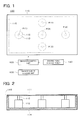
- FIG. 1 is a schematic view showing an acoustic vibration reproducing apparatus according to a first embodiment of the present invention.
- FIG. 2 is a cross-sectional view showing the internal structure of an acoustic vibration part according to the first embodiment.
- FIG. 3 is a chart showing an example of a table in an excited point control table.
- FIG. 4 is a chart showing an example of a table in the excited point control table.
- FIG. 5 is a table showing a correspondence relation between fundamental frequencies f0 and vibration modes of a top of a violin.
- FIG. 6 is a schematic view showing the vibration modes that the top and a back of the violin have.
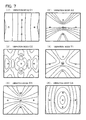
- FIG. 7A to FIG. 7F are schematic views showing results of simulations of a vibration state of a vibration plate.
- FIG. 8 is a perspective view showing an acoustic vibration reproducing apparatus according to a second embodiment of the present invention.
- FIG. 9 is a cross-sectional view showing the internal structure of an acoustic vibration part according to the second embodiment.
- FIG. 10 is a schematic view showing an acoustic vibration reproducing apparatus according to a third embodiment of the present invention.
- FIG. 11 is a cross-sectional view showing the internal structure of an acoustic vibration part according to the third embodiment.
- FIG. 12 is a perspective view showing an acoustic vibration part according to a fourth embodiment.
- FIG. 13 is a cross-sectional view showing the acoustic vibration part according to the fourth embodiment.
- FIG. 14 is a view showing a correspondence relation between faces of a vibrating part and a stationary part.
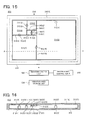
- FIG. 15 is a schematic view showing an acoustic vibration reproducing apparatus according to a fifth embodiment of the present invention.
- FIG. 16 is a cross-sectional view showing the internal structure of an acoustic vibration part according to the fifth embodiment.
- FIG. 17 is a schematic view showing an acoustic vibration reproducing apparatus according to a sixth embodiment of the present invention.
- FIG. 18 is a cross-sectional view showing the internal structure of an acoustic vibration part according to the sixth embodiment.
- FIG. 1 is a schematic view showing an acoustic vibration reproducing apparatus 100 according to a first embodiment of the present invention.
- FIG. 2 is a cross-sectional view showing the internal structure of an acoustic vibration part 110 of the acoustic vibration reproducing apparatus 100.
- the acoustic vibration reproducing apparatus 100 has the acoustic vibration part 110, a vibration control unit 120, a vibration mode storage unit 130, and an excited point control table 140.
- the acoustic vibration part 110 converts a signal output from the vibration control unit 120 into a vibration, and has a vibration plate 111, five exciting units 112, five vibration transmitting parts 113, an enclosure 114, and a sealing part 115.
- the vibration plate 111 vibrates when vibrations are applied to excited points P (1) to P(5) by the exciting units 112. At this time, if at least one of the vibrations applied to the excited points P(1) to P (5) is different from the others, a plurality of different vibrations are applied to the vibration plate 111.
- "Different vibrations" refers to vibrations different in at least one of frequency, amplitude, and phase.
- the vibration plate 111 By the plural different vibrations being applied to the vibration plate 111, wavefronts made by the plural smoothly coupled acoustic vibrations are formed on a front surface of the vibration plate 111. At this time, nodes and antinodes of the vibrations are distributed on the vibration plate 111. This distribution can be considered as a vibration mode of the vibration plate 111. Specifically, the vibration mode and the distribution of the nodes and antinodes of the vibrations on the vibration plate 111 are in a correspondence relation. As will be described later, the vibration plate 111 can be vibrated in, for example, vibration modes A0, C1 to C4, and Tl.
- a vibration mode occurs when the vibrations applied to the excited points P (1) to P (5) by the exciting units 112 travel in the vibration plate 111 to be superimposed on one another on the vibration plate 111. Therefore, the vibration mode is not determined only by the vibrations applied to the excited points P(1) toP(5) (frequency ratio, amplitude ratio, phase difference) but depends on the shape, size, thickness, vibration transmission property, restriction conditions (for example, whether an end portion of the vibration plate 111 is fixed or free), and the like of the vibration plate 111.
- the excited points P (1) to P (5) are appropriately disposed on the vibration plate 111.
- the excited points P(1) to P(5) are disposed so that a desired vibration mode is effectively generated.
- a desiredvibrationmode to be reproduced is a vibration mode of the top of a violin
- Positions of the antinodes generally differ depending on a vibration mode, and therefore, a possible way to reproduce a pluralityvibration modes is to dispose the excited points P at all the positions of the antinodes in all the vibration modes.
- the excited points need not be disposed at the positions of the antinodes of the vibration.
- the vibration plate 111 is a quadrangular (here, rectangular) flat plate.
- the rectangular shape is adopted because the rectangular shape can generate various vibration modes more easily than a square shape.
- a rectangle is more asymmetric than a square.
- a highly symmetric shape tends to produce less diversified vibration modes.
- the external shape of the vibration plate 111 may be an arc shape such as a circular shape or an elliptical shape, or may be any other shape.
- a surface of the vibration plate 111 may be a curved surface instead of a planar surface (flat plate) .
- the vibration plate 111 As a material of the vibration plate 111, usable are various materials such as wood (solid lumber, plywood (lauan plywood), MDF (Medium Density Firberboard, a plate made of wood fibers consolidated with an adhesive)), glass, metal, and a resin material (acryl or the like).
- wood solid lumber, plywood (lauan plywood), MDF (Medium Density Firberboard, a plate made of wood fibers consolidated with an adhesive)
- glass glass
- metal and a resin material (acryl or the like).
- the vibration plate 111 is formed to have substantially the same size and is made of the same material as those of the top of the violin (for example, size: 200 mm x 360 mm x 3 mm, material: wood).
- the top of the violin has a thickness less than 3 mm, but is varnished to have increased rigidity. Consideringthis, if wood is used as it is as the material, itsthickness is preferably about 3 mm. If a varnished wood or glass plate is used as the vibration plate 111, the thickness of the vibration plate 111 is smaller.
- the five exciting units 112 are exciting devices (a kind of drivers) capable of independently applying vibrations to the respective five excited points P(1) to P (5) on the vibration plate 111. So-called vibrators also function as the exciting units 112.
- the exciting units 112 apply the vibrations to the excited points P(1) to P(5) of the vibration plate 111 by, for example, magnetic means such as voice coils or electric means such as piezoelectric elements.
- As the exciting units 112, usable is a vibrating device for speakers (for example, GY-1) manufactured by FOSTEX.
- the vibrations are applied in a vertical direction of the surface of the vibration plate 111.
- the vibrations can be also applied in an oblique direction of the vibration plate 111 instead of the vertical direction.
- the five vibration transmitting parts 113 couple the five exciting units 112 and the excited points P(1) to P (5) respectively to transmit the vibrations from the exciting units 112 to the excited points P.
- the vibration transmitting parts 113, the vibration plate 111, and the exciting units 112 are fixed to one another by screwing, bonding, or the like.
- An example of a usable material of the vibration transmitting parts 113 is a high-rigidity material such as a metal stick.
- the enclosure 114 is intended for preventing a sound pressure generated on the front surface of the vibration plate 111 from being cancelled by a sound pressure generated on a rear surface thereof.
- an air pressure difference occurs in a space adj acent to its front surface to generate an acoustic wave.
- an air pressure difference in opposite phase to that on the front surface occurs. Therefore, if air near the rear surface can freely move to the vicinity of the front surface, the air pressure differences are cancelled by each other.
- the inside of the enclosure 114 is tightly closed and the acoustic wave from the rear surface of the vibration plate 111 stays in the enclosure 114 (interception of the acoustic wave).
- the enclosure 114 has a bottom plate and four side plates, and on its open top, the vibration plate 111 is disposed.
- the sealing part (gasket) 115 is disposed around a gap near outer peripheries (end portions (edges, corners, or the like)) of the enclosure 114 and the vibration plate 111 (is disposed in a ring form) and it seals the enclosure 114 to restrict the flow of the acoustic waves out of the enclosure 114.
- the sealing part 115 is made of a highly flexible material (with a small Young's modulus), for example, rubber so as not to restrict the vibration of the vibration plate 111 at the outer periphery. This allows the outer periphery of the vibration plate 111 to be a so-called free end. On the other hand, if the outer periphery of the vibration plate 111 is formed as a so-called fixed end, a high-rigidity material (with a large Young's modulus) is used. It can be appropriately decided whether to form the outer periphery of the vibration plate 111 as a free end or a fixed end.
- forming the outer periphery of the vibration plate 111 as the free end can more increase diversity of the vibration modes that the vibration plate 111 can have.
- a node of the vibration falls on the outer periphery of the vibration plate 111 formed as a fixed end.
- both a node and an antinode of the vibration can fall on the outer periphery of the vibration plate 111 formed as a free end.
- the flexibility/rigidity of the sealing part 115 greatly depends on its shape as well as the Young' s modulus of its constituent material.
- the sealingpart 115 has a semicircular cross section, tapering toward the vibration plate 111.
- a practical width of the sealing part 115 becomes smaller, which renders the vibration plate 111 a greater degree of freedom.
- the degree of freedomof thevibrationplate 111 depends on its width. Decreasing the width of the sealing part 115 results in a higher degree of freedom of the vibration of the vibration plate 111, but on the other hand, results in a lowered strength of the sealing part 115.
- By changing the width of the sealing part 115 in its height direction it is possible to ensure both the degree of freedom of the vibration plate 111 and the strength of the sealing part 115.
- a material having vibration absorbency (synonymous with sound absorbency since acoustic vibration is an issue here) is used for the sealing part 115.
- the reflection of the vibration from the outer periphery (end portion) of the vibration plate 111 is restricted, enabling easier control of the vibration of the vibration plate 111. If the vibration is reflected from the outer periphery of the vibration plate 111, this reflected wave conflicts with the vibrations applied to the excited points P, which may make it difficult to control the vibration of the vibration plate 111.
- the use of a sound absorbing material for the sealing part 115 results in an energy loss of the applied vibrations. Therefore, in order to reduce the energy loss of the vibrations, it is also conceivable to use a material with lowvibration absorbency for the sealing part 115.
- vibration absorbing material is a porous material such as urethane rubber.
- urethane rubber When an acoustic vibration enters and diffuses in the porous material, the energy of the vibration is transformed into heat energy, resulting in a small reflected wave.
- the vibration control unit 120 controls the vibrations applied by the exciting units 112 (1) to 112(5) (frequencies, amplitudes, phases) independently.
- Sound generated by the vibration of the vibration plate 111 is defined in terms of a reference vibration (displacement from a reference point at time t) Ws (t) and a vibration mode M (t).
- the reference vibration Ws (t) determines basic elements of acoustic vibration (tone and intensity of sound) generated by the vibration plate 111 at the time t.
- the vibration mode M (t) is equivalent to spatial distribution of the acoustic vibration (sound field) generated by the vibration plate 111 at the time t.
- an acoustic vibration W (t) desired to be reproduced for example, a recorded waveform of performance of the violin is usable.
- the acoustic vibration W(t) needs to be multiplied by an appropriate coefficient for the adjustment of an absolute value of the displacement of the vibration plate 111.
- the vibration mode of the vibration plate 111 is determined by relative vibrations (frequency ratio, amplitude ratio, phase difference) at the excited points P(1) to P(5).
- the "frequencyratio” can be defined as a ratio of the frequency at each of the other excited points to the frequency at the reference excited point Ps.
- the "amplitude ratio” can be defined as a ratio of the amplitude at each of the other excited points to the amplitude at the reference excited point Ps.
- the "phase difference” can be defined as a relative phase at each of the other excited points P to the phase at the reference excited point Ps.
- the vibration mode storage unit 130 stores the reference vibration Ws(t) and the vibration mode M(t) in correspondence to time (time shift of the vibration state). That is, the vibration mode storage unit 130 functions as a first storage unit storing a first table showing the vibration mode of the vibration plate 111 and time in correspondence to each other. Figuratively speaking in terms of musical instrument performance, the vibration mode storage unit 130 stores a score -
- the excited point control table 140 stores, as a table, a relation between the vibration modes of the vibration plate 111 and relative vibrations of the exciting units 112.
- the excited point control table 140 functions as a second storage unit storing a second table showing the vibration modes of the vibration plate 111 in correspondence to at least one of a frequency ratio, an amplitude ratio, and a phase difference of each of the vibrations applied by the exciting units 112.
- FIG. 3 and FIG. 4 are charts showing an example of tables in the excited point control table 140, the phase differences and the frequency ratios being separately shown in the respective tables in correspondence to the vibration modes. These tables correspond to the vibration modes of the top of the violin. That is, FIG. 3 and FIG. 4 show the phase differences and the amplitude ratios corresponding to the vibration modes A0, C1 to C4, and T1 that the top of the violin has. In this example, it is assumed that the vibrations applied to the excited points P(1) to P (5) have the same amplitude, but by making these amplitudes different, it is possible to generate more diversified vibration modes.
- phase differences and the frequency ratios maybe shown in one table though shown in the different tables here.
- the operation of the acoustic vibration reproducing apparatus 100 will be described.
- the reproduction of an acoustic vibration from a musical instrument, in particular, from a top of a violin will be taken as an example.
- a vibration of a back of the violin will be disregarded though its vibration state is not always the same as a vibration state of the top.
- a vibration state to be reproduced by the acoustic vibration reproducing apparatus 100 is decided.
- This vibration state is defined in terms of the reference vibration Ws (t) and the vibration mode M(t).
- the vibration mode to be reproduced can be decided by using the following methods (1), (2), for instance.
- a vibration state of the top of the violin at this time can be measured by holographic interferometry, for instance.
- holographic interferometry by using a hologram, wavefronts of reflected lights from the reproduction target before and after the reproduction target is deformed are interfered with each other and interference fringes showing the distribution of the deformation are generated.
- the deformation (vibration) of the top of the violin can be measured with high sensitivity.
- the vibration mode can be decided based on the fundamental frequency in the following procedure, for instance.
- Performance sound of the violin is recorded and the acoustic vibration W(t) is obtained.
- This acoustic vibration W(t) is multiplied by a predetermined coefficient, thereby defining the reference vibration Ws(t).
- the fundamental frequency f0(t) is extracted from the obtained acoustic vibration W(t).
- the fundamental frequency f0 (t) means a frequency having the greatest influence on an acoustic sense of a human being, that is, a frequency that is recognized as being "fundamental" among frequency components of sound.
- the acoustic vibration W(t) is subjected to frequency resolution and the result is shown as a spectrogram F (t), and the fundamental frequency f0(t) at the time (t) is specified.
- FFT Fast Fourier Transform
- the lowest frequency with the largest sound pressure in the spectrogram F (t) is the fundamental frequency f0(t) .
- the obtained acoustic vibration W(t) may have a frequency component other than the fundamental frequency f0 (t) (in particular, a harmonic).
- a body of the violin resonates due to the vibration, so that a harmonic component or the like is amplified. Therefore, it is conceivable to use various methods such as cepstrum.
- the spectrogram F (t) of the acoustic vibration W (t) is transformed into a logarithm, which in turn is inversely fast-Fourier transformed.
- FIG. 5 is a table showing a correspondence relation between the fundamental frequency f0 and the vibration mode of the top of the violin. As shown in FIG. 5 , the top of the violin takes the vibration modes A0, C1 to C4, and T1 depending on the fundamental frequency f0 (t).
- FIG. 6 is a schematic view showing the vibration modes A0, C1 to C4, and T1 that the top and the back of the violin have.
- a set of the reference vibration Ws (t) and the vibration mode M(t) is sequentially output from the vibration mode storage unit 130 to the vibration control unit 120, and the vibrations to be applied to the excited points P(1) toP(5) are decided with reference to the excited point control table 140.
- the vibration mode of the vibration plate 111 changes depending on the phase difference or the amplitude ratio of the vibrations applied to the excited points P(1) to P(5). As previously described, the phase differences and the amplitude ratios corresponding to the vibration modes A0, C1 to C4, T1 that the top of the violin has are shown in FIG. 3 and FIG. 4 .
- the acoustic vibration reproducing apparatus 100 stores both the reference vibration Ws(t) and the vibration mode M(t). However, the acoustic vibration reproducing apparatus 100 may store only the reference vibration Ws (t) and may automatically estimate the vibration mode M (t) from the reference vibration Ws (t). In this case, the acoustic vibration reproducing apparatus 100 extracts the fundamental frequency f0 (t) from the reference vibration Ws(t) and estimates the vibration mode M(t) by using the table or the like showing the correspondence relation between the reference frequency f0 and the vibration mode M.
- the exciting units 112 apply the vibrations to the excited points P (1) to P (5) to acoustically vibrate the vibration plate 111.
- FIG. 7A to FIG. 7F are schematic views showing the results of simulations of the vibration state of the vibration plate 111.
- positions shown by circled “+” correspond to the excited points P(1) to P(5).
- FIG. 7A to FIG. 7F correspond to the vibration modes C1, A0, C2, T1, C3, C4 of the top of the violin which are shown in FIG. 6 .
- the vibrations corresponding to the vibration modes of the top of the violin can be generated on the vibration plate 111. That is, it is possible to reproduce the distribution of acoustic waves along the surface of the top of the violin (shape information).
- the reflection of waves at edges (end portions) of the vibration plate 111 is disregarded and only primary propagation waves from the excited points P are handled.
- the waves reflected from the edges of the vibration plate 111 can be thought to be small compared with the primary propagation waves transmitted directly from the excited points P.
- the vibrations As described above, by applying the vibrations to the plural excited points P of the vibration plate 111, wavefronts made by the plural smoothly coupled vibrations can be generated on the front surface of the vibration plate 111.
- the vibrations including the fundamental frequency f0 (t) and its harmonics are applied to the different excited points P and the vibrations are synthesized on the surface of the vibration plate 111.
- the vibration plate 111 curves and sound is emitted along the curved surface.
- a “speaker array” system is a possible method of forming the wavefronts made by a plurality of smoothly coupled vibrations as described above.
- the "speaker array” system a large number of typical loud speakers are disposed planarly and are controlled independently. In this system, however, the individual speaker can generate only single sound and occupies some space, which makes it difficult to ensure smooth coupling of waves generated by the speakers.
- the acoustic vibration reproducing apparatus 100 does not directly reproduce a sound image, but reproduces the vibration and the shape of the surface of a sounding body (for example, a musical instrument) to synthesize the generated wavefronts. As a result, the smoothness of the wavefronts of acoustic vibrations generated from the vibration plate 111 can be easily ensured.
- the following second to fourth embodiments can provide the same advantages.
- FIG. 8 is a perspect ive view showing an acoust ic vibrat ion reproducing apparatus 200 according to the second embodiment of the present invention.
- FIG. 9 is a cross-sectional view showing the internal structure of an acoustic vibration part 210 of the acoustic vibration reproducing apparatus 200 of the present invention.
- the acoustic vibration reproducing apparatus 200 has the acoustic vibration part 210, a vibration control unit 220, a vibration mode storage unit 230, and an excited point control table 240.
- the whole acoustic vibration part 210 has the shape of a violin and is capable of generating a vibration in a vibration mode closer to the original vibration mode of the violin.
- the acoustic vibration part 210 has vibration plates 211(1), 211(2), exciting units 212 (1), 212 (2), vibration transmitting parts 213 (1), 213 (2), an enclosure 214, sealing parts 215 (1), 215 (2), and a brace 216 and is supported on a holder 217.
- the vibration plates 211 (1), 211 (2) have shapes (external shapes, dimensions, curved surfaces) corresponding to a top and a back of a violin respectively. Vibrations of both the top and the back of the violin, that is, a sound field generated from the violin can be faithfully reproduced.
- the exciting units 212(1), 212(2) vibrate the vibration plates 211(1), 211(2) respectively and are disposed on both surfaces of the brace 216.
- the enclosure 214 has a shape corresponding to a side panel of the violin, and the vibration plates 211(1), 211(2) which are attached to the enclosure 214 as its top plate and bottom plate seal the inside of the enclosure 214 to prevent the vibrations from being emitted out of the enclosure 214.
- the sealing parts 215(1), 215(2) are disposed for the vibration plates 211 (1), 211 (2) respectively to extend along upper and lower edges of the enclosure 214 and restrict the flow of acoustic waves out of the enclosure 214.
- the brace 216 is a plate having a shape of a cross and its four ends are fixed to the enclosure 214.
- the exciting units 212 (1), 212(2) are disposed on an upper and a lower surface of the brace 216 to independently control the vibration plates 211(1), 211(2) respectively, thereby enabling faithful reproduction of the vibrations of the top and the back of the violin. That is, the brace 216 functions as a stationary part on which the exciting units 212 are disposed.
- the brace 216 preferably has rigidity since it serves as a basis of the vibrations of the vibration plates 211 (1), 211 (2) .
- the vibration control unit 220 controls the two vibration plates 211(1), 211 (2) independently via the exciting units 212 (1), 212(2).
- the vibration mode storage unit 230 stores a reference vibration Ws (t) and a vibration mode M (t) of the violin, for instance, in correspondence to time (time shift of a vibration state).
- the excited point control table 240 stores, as a table, a relation between vibration modes of the vibration plates 211 (1), 211 (2) and relative vibrations of the exciting units 212(1), 212 (2).
- the vibration states of the top and the back of the violin may be in the same vibration mode or may be in different vibration modes. Therefore, vibrations applied to the vibration plates 211 (1), 211 (2) are not completely the same.
- FIG. 10 is a schematic view showing an acoustic vibration reproducing apparatus 300 according to the third embodiment of the present invention.
- FIG. 11 is a cross-sectional view showing the internal structure of an acoustic vibration part 310 of the acoustic vibration reproducing apparatus 300.
- the acoustic vibration reproducing apparatus 300 has the acoustic vibration part 310, a vibration control unit 320, a vibration mode storage unit 330, and an excited point control table 340.
- the acoustic vibration part 310 has vibration plates 311 (1) to 311 (3), exciting units 312 (1) to 312 (3), vibration transmitting parts 313(1) to 313(3), an enclosure 314, sealing parts 315(1) to 315 (4), fixing parts 316 (1) to 316 (3), and partition plates 317 (1), 317(3).
- the vibration plates 311(1) to 311(3) have a shape corresponding to parts into which a regular triangle is trisected with respect to its center and the whole assembly of the vibration plates 311 (1) to 311 (3) forms a substantially regular triangle.
- the vibration plates 311(1) to 311(3) vibrate while being coupled to one another via the sealing parts 315(1) to 315(3).
- An angular relation among the vibration plates 311 (1) to 311 (3) along the sealing parts 315 (1) to 315 (3) can be changed, thereby improving a degree of freedom of vibrations of the vibration plates 311 (1) to 311(3) while keeping a continuous vibration state as a whole.
- vibrations continue and wavefronts of acoustic vibrations generated from the vibration plates 311(1) to 311(3) are coupled, so that continuous wavefronts are generated on front surfaces of the vibration plates 311(1) to 311(3).
- the vibrationplates 311 (1) to 311 (3) are fixed by the fixing parts 316 (1) to 316 (3) respectively, and vibrations are applied to each of the vibration plates 311 (1) to 311 (3) by two of the exciting units 312. For example, if the vibrations applied by the two exciting units 312 have no phase difference (are in the same phase), the vibration plate 311 bends upward and downward with the fixing part 316 as a fulcrum. Further, if the phase difference of the vibrations applied by the two exciting units 312 is 180°, the vibration plate 311 twists with respect to the fixing part 316. Combining the vibrations of the respective vibration plates 311 (1) to 311 (3) makes it possible to appropriately set the wavefronts of the vibration generated from the whole vibration plate 311.
- the exciting units 312(1) to 312(3) are disposed at the positions overlapping with the borders (edges, end portions) of the vibration plates 311(1) to 311(3) respectively, each capable of simultaneously applying the vibration to two of the vibration plates 311. As a result, it is possible to ensure continuity of the vibrations on the vibration plates 311 (1) to 311 (3) and efficiently vibrate the vibration plates 311.
- the enclosure 314 has a bottom plate and three side plates, and the movement of air (flow of acoustic waves) between the outside and inside of the enclosure 314 is intercepted so that waves generated from front surfaces of the vibration plates 311 are not cancelled by waves generated from rear surfaces thereof.
- the enclosure 314 is partitioned by the partition plates 317 (1) to 317 (3) to be divided into three spaces corresponding to the vibration plates 311 (1) to 311(3) respectively. Sounds in the three spaces are intercepted by the partition plates 317 (1) to 317 (3), so that different acoustic spaces are formed. This is intended to reduce an influence that each of the vibrations of the respective vibration plates 311(1) to 311(3) has on the vibrations of the others, thereby ensuring easiness of control.
- the sealing parts 315(1) to 315(3) are disposed on end surfaces of the partition plates 317 (1) to 317(3) and end surfaces of the side plates of the enclosure 314 to seal gaps between the vibration plates 311(1) to 311(3) and the enclosure 314, thereby restricting the flow of the acoustic waves out of the enclosure 314.
- the fixing parts 316(1) to 316 (3) are fixing members fixing the respective vibration plates 311(1) to 311(3) to the enclosure 314, and are, for example, screws or adhesives.
- the exciting units 312 may be disposed in place of the fixing parts 316(1) to 316(2), which can improve a degree of freedom of the vibrations of the vibration plates 311.
- FIG. 12 and FIG. 13 are a perspective view and a cross-sectional view showing an acoustic vibration part 410 of an acoustic vibration reproducing apparatus 400 according to the fourth embodiment of the present invention.
- the acoustic vibration part 410 has a vibrating part 411, exciting units 412, vibration transmitting parts 413, a stationary part 414, sealing parts 415, a brace 416, and a pedestal 417.
- the acoustic vibration reproducing apparatus 400 has a vibration control unit 420, a vibration mode storage unit 430, and an excited point control table 440, which are not shown.
- FIG. 14 is a view showing a correspondence relation between the faces of the vibrating part 411 and the stationary part 414.
- the faces of the vibrating part 411 and the stationarypart 414 are substantially parallel to each other.
- Three vibration plates 418(1) to 418(3) are disposed on each of the faces of the vibrating part 411.
- the three vibration plates 418(1) to 418 (3) have shapes corresponding to those of the vibration plates 311(1) to 311(3) of the third embodiment, and vibrations V are applied to excited points Q (1) to Q(6) by the exciting units 412 through the vibration transmitting parts 413, the exciting units 412 and the vibration transmitting parts 413 being disposed at positions R(1) to R(6) of the stationary part 414 respectively. That is, unlike the third embodiment, the vibrations V can be applied to corners of the vibration plates 418 as well. For easier viewing of the drawing, some of the exciting units 412 and the vibration transmitting parts 413 are not shown.
- the sealing parts 415 are disposed between the vibration plates 418. As a result, the flow of acoustic vibrations out of the vibrating part 411 (space between the vibrating part 414 and the stationary part 411) is prevented.
- An example usable as the sealing parts 415 is a flexible material such as rubber.
- the stationary part 414 is fixed to the brace 416 and has the exciting units 412 thereon.
- the stationary part 414 is made of a vibration absorbing (sound insulating) material, so that the flow of the acoustic vibrations through the brace 416 is restricted.
- FIG. 15 is a schematic view showing an acoustic vibration reproducing apparatus 500 according to the fifth embodiment of the present invention.
- FIG. 16 is a cross-sectional view showing the internal structure of an acoustic vibration part 510 of the acoustic vibration reproducing apparatus 500 taken along the A-A line in FIG. 15 .
- the acoustic vibration reproducing apparatus 500 has the acoustic vibration part 510, a vibration control unit 520, a vibration mode storage unit 530, and an excited point control table 540.
- the acoustic vibration part 510 has vibration plates 511 (1) to 511 (6), exciting units 512 (1) to 512 (6), vibration transmitting parts 513(1) to 513 (6), an enclosure 514, and sealing parts 515 (1) to 515 (6).
- Each of the vibration plates 511 (1) to 511 (6) has a square shape and the whole assembly thereof forms a rectangle.
- a length ratio of sides of the vibration plates 511(1) to 511(6) is 1 : 1 : 2 : 3 : 5 : 8, which is a Fibonacci sequence.
- the lengths of the sides of the vibration plates 511(1) to 511(6) are defined according to the Fibonacci sequence, so that the assembly (511 (1) to 511 (n)) of the first vibration plate 511 (1) to the n-th (n: integer) vibration plate 511 (n) can always form a rectangle.
- the excitingunits512 (1) to 512 (5) are disposed at positions overlapping with borders (sides) of the vibration plates 511 (1) to 511(6) respectively, each capable of applying a vibration simultaneously to two of the vibration plates 511. Further, the exciting unit 512 (6) is disposed near a border between the vibration plate 511 (6) and a top plate of the enclosure 514 so as to overlap with the vibration plate 511(6). Incidentally, the exciting unit 512 (6) may be disposed at other position (for example, at a position overlapping with any of the vibration plates 511(1) to 511(5)).
- the enclosure 514 has the top plate (having an opening), a bottom plate, and four side plates to intercept the movement of air (flow of an acoustic wave) out of the enclosure 514.
- the sealing parts 515 (1) to 515 (5) seal the borders between the vibration plates 511 (1) to 511 (6) .
- the sealing part 515 (6) seals a gap between the vibration plates 511 (1) to 511(6) and the enclosure 514.
- the sealing parts 515(1) to 515 (6) restrict the flow of the acoustic waves out of the enclosure 514.
- the vibration plates 511 (2) to 511 (6) are similar to one another (square) and lengths of their sides are different to one another.
- vibrations in a common vibration mode M and with different natural frequencies f can be induced on the vibration plates 511(2) to 511(6).
- the same vibration modes M vibration modes in which the distributions of vibrations (distributions of nodes and antinodes of the vibrations) on the vibration plates 511 are similar to one another
- the natural frequency of each of the vibration plates 511 depends on the length of its side (the natural frequency of a square vibration plate 511 is inversely proportional to a square value of the length of its side) .
- the exciting units 512(2) to 512(5) are disposed at positions overlapping with the borders of the vibration plates 511(2) to 511(6), and amplitudes at the excited points corresponding to the exciting units 512 (1) to 512 (5) are equal. Nevertheless, the vibration modes of the vibration plates 511(2) to 511(6) can be made different.
- vibration plates 511(2) to 511(6) different in size it is possible to secure diversity of the natural frequency or the vibration mode and accurately reproduce complicated vibrations.
- the lengths of the sides of the vibration plates 511(2) to 511 (6) are increased in this order and the vibration plates 511 (2) to 511 (6) are arranged in an anticlockwise spiral form. That is, the vibration plates 511 different in size are disposed in a well-balanced manner, so that the frequency distribution of acoustic waves generated in the upward/downward and rightward/leftward directions are kept well-balanced.
- the vibration plate 511(1) is the same in size as the vibration plate 511 (2), but can contribute to diversity of the natural frequency and the vibration mode if its excitation by the exciting unit 512 is controlled. However, the vibration plate 511(1) may be omitted. For example, the vibration plate 511 (1) may be replaced by a stationary member fixed to the enclosure 514.
- FIG. 17 is a schematic view showing an acoustic vibration reproducing apparatus 600 according to the sixth embodiment of the present invention.
- FIG. 18 is a cross-sectional view showing the internal structure of an acoustic vibration part 610 of the acoustic vibration reproducing apparatus 600 taken along the B-B line in FIG. 17 .
- the acoustic vibration reproducing apparatus 600 has the acoustic vibration part 610, a vibration control unit 620, a vibration mode storage unit 630, and an excited point control table 640.
- the acoustic vibration part 610 has vibrationplates 611 (1, 1) to 611 (3, 3), exciting units 612, vibration transmitting parts 613, an enclosure 614, sealingparts 615 (6151(1) to 6151 (4), 6152(1) to 6152(3)), and a stationary part 616.
- the whole assembly of the vibration plates 611(1, 1) to 611(3, 3) has a substantially circular shape and is divided into three sections in a diameter direction and into three sections in an argument direction.
- the vibration plates 611(1, 1) to 611(3, 3) are different in length in the diameter direction and in angle in the argument direction (here, a length ratio is 1 : 2 : 3 and an angle ratio is 1 : 2 : 3 (60° : 120° : 180°)). That is, each of the vibration plates 611 (1, 1) to 611 (3, 3) has a substantially fan shape.
- vibration modes induced on the vibration plates 611(1, 1) to 611(3, 3) that is, reproduced vibrations are limited to simple ones.
- effective vibration modes can be induced on the vibration plates 611 (1, 1) to 611(3, 3).
- the vibration plates 611 (1, j) to 611 (3, j) (j : integer) arranged in the diameter direction are similar to one another and are different in area.
- vibrations in common vibration modes M and with different natural frequencies f can be induced on the vibration plates 611 arranged in the diameter direction.
- the natural frequencies of the vibration plates 611(1, j) to 611 (3, j) decrease in this order.
- the vibration plates 611 (i, 1) to 611 (i, 3) (i: integer) arranged in the argument direction are different in aspect ratio (a ratio of lengths in the diameter direction and the argument direction).
- vibration modes with different aspect ratios vibration modes in which the aspect ratios of the distributions of vibrations (distributions of nodes and antinodes of the vibrations) on the vibration plates 611) are different
- the exciting units 612 are disposed at positions overlapping with the vibration plates 611 (1, 1) to 611(3, 3) and their borders (edges), each capable of applying a vibration simultaneously to two of the vibration plates 611. As a result, it is possible to ensure continuity of vibrations on the vibration plates 611(1, 1) to 611 (3, 3) and efficiently vibrate the vibration plates 611 (1, 1) to 611 (3, 3).
- the enclosure 614 has a top plate (having an opening), a bottom plate, and a side plate to intercept the movement of air (flow of acoustic waves) out of the enclosure 614. This is intended to reduce an influence that the vibration of each of the vibration plates 611 (1, 1) to 611 (3, 3) has on the other vibration plates 611, thereby ensuring easiness of control.
- the sealing parts 615 (6151 (1) to 6151 (4), 6152(1) to 6152(3)) seal the borders of the vibration plates 611(1, 1) to 611(3, 3), the enclosure 614, and the stationary part 616 to restrict the flow of the acoustic waves out of the enclosure 614.
- the sealing parts 6151 (1) to 6151 (4), 6152 (1) to 6152 (3) extend in the argument direction and the diameter direct ion respectively to seal the borders of the vibration plates 611(1, 1) to 611(3, 3), the enclosure 614, and the stationary part 616.
- the stationary part 616 is fixed on the bottom plate of the enclosure 614.
- the five exciting units apply the vibrations to the single vibration plate.
- the number of the exciting units may be appropriately set in a range of two or more. Increasing the number of the exciting units enables more diversified vibrations of the vibration plate.
- a shape of another musical instrument for example, a shape of a guitar or the like canbe adopted.
- the three vibration plates are combined to form a surface.
- the number of the combined vibration plates may be one, two, or four or more.
- the number of faces of the polyhedron in the fourth embodiment other numbers, for example, 6, 8, and 12 can be adopted.
- the combination of spherical faces canbe adopted.
- the vibration plates 511, 611 are not fixed to the enclosures 514, 614 and thus can vibrate freely (a structure corresponding to the fixing parts 316 of the third embodiment is not provided) .
- the vibration plates 511, 611 may be partly fixed so that the vibrations thereof are mechanically restricted.
Landscapes
- Engineering & Computer Science (AREA)
- Multimedia (AREA)
- Physics & Mathematics (AREA)
- Acoustics & Sound (AREA)
- Signal Processing (AREA)
- Electrophonic Musical Instruments (AREA)
- Diaphragms For Electromechanical Transducers (AREA)
- Obtaining Desirable Characteristics In Audible-Bandwidth Transducers (AREA)
- Circuit For Audible Band Transducer (AREA)
- Fittings On The Vehicle Exterior For Carrying Loads, And Devices For Holding Or Mounting Articles (AREA)
- Apparatuses For Generation Of Mechanical Vibrations (AREA)
Abstract
Description
- This application is based upon and claims the benefit of priority from the prior Japanese Patent Application No.
2007-050751 - The present invention relates to an acoustic vibration reproducing apparatus reproducing an acoustic vibration.
- Various techniques for reproducing sound have been developed. For example, there has been made public a technique relating to a panel speaker in which a flat plate-shaped vibration plate is driven by a driver (see
JP-A 2005-117217 - A sounding body such as, for example, a musical instrument produces sound by the vibration of its surface. At this time, many sounding bodies each have a certain degree of size rather than being a point, and different vibrations (vibrations different in at least one of frequency, amplitude, and phase) are continuously mixed on the surface of the sounding body. As a result, an acoustic wave generated from the sounding body reflects a three-dimensional structure of the sounding body and accordingly has a complicated waveform with its frequency, phase, or amplitude changing in a surface direction. Further, as is pointed out with respect to an effect (feeling of presence) of binaural recording, a human being hears, as sound, not only an acoustic wave directly reaching his/her ears but also an interference ascribable to an acoustic wave diffracted and reflected by various parts of his/her body (for example, head). From the above, it is thought that reproducing sound as a surface sound source can realize a higher feeling of presence than reproducing sound as a point sound source.
- Inview of the above, it is anobject of the present invention to provide an acoustic vibration reproducing apparatus capable of reproducing an acoustic vibration including different coupled vibrations.
- An acoustic vibration reproducing apparatus according to one aspect of the present invention includes: a first vibration plate; a first exciting unit applying a vibration to the first vibration plate; and a second exciting unit applying, to the first vibration plate, a vibration different from the vibration applied by the first exciting unit.
-
FIG. 1 is a schematic view showing an acoustic vibration reproducing apparatus according to a first embodiment of the present invention. -
FIG. 2 is a cross-sectional view showing the internal structure of an acoustic vibration part according to the first embodiment. -
FIG. 3 is a chart showing an example of a table in an excited point control table. -
FIG. 4 is a chart showing an example of a table in the excited point control table. -
FIG. 5 is a table showing a correspondence relation between fundamental frequencies f0 and vibration modes of a top of a violin. -
FIG. 6 is a schematic view showing the vibration modes that the top and a back of the violin have. -
FIG. 7A to FIG. 7F are schematic views showing results of simulations of a vibration state of a vibration plate. -
FIG. 8 is a perspective view showing an acoustic vibration reproducing apparatus according to a second embodiment of the present invention. -
FIG. 9 is a cross-sectional view showing the internal structure of an acoustic vibration part according to the second embodiment. -
FIG. 10 is a schematic view showing an acoustic vibration reproducing apparatus according to a third embodiment of the present invention. -
FIG. 11 is a cross-sectional view showing the internal structure of an acoustic vibration part according to the third embodiment. -
FIG. 12 is a perspective view showing an acoustic vibration part according to a fourth embodiment. -
FIG. 13 is a cross-sectional view showing the acoustic vibration part according to the fourth embodiment. -
FIG. 14 is a view showing a correspondence relation between faces of a vibrating part and a stationary part. -
FIG. 15 is a schematic view showing an acoustic vibration reproducing apparatus according to a fifth embodiment of the present invention. -
FIG. 16 is a cross-sectional view showing the internal structure of an acoustic vibration part according to the fifth embodiment. -
FIG. 17 is a schematic view showing an acoustic vibration reproducing apparatus according to a sixth embodiment of the present invention. -
FIG. 18 is a cross-sectional view showing the internal structure of an acoustic vibration part according to the sixth embodiment. - Hereinafter, embodiments of the present invention will be described in detail with reference to the drawings.
-
FIG. 1 is a schematic view showing an acousticvibration reproducing apparatus 100 according to a first embodiment of the present invention.FIG. 2 is a cross-sectional view showing the internal structure of anacoustic vibration part 110 of the acousticvibration reproducing apparatus 100. The acousticvibration reproducing apparatus 100 has theacoustic vibration part 110, avibration control unit 120, a vibrationmode storage unit 130, and an excited point control table 140. - The
acoustic vibration part 110 converts a signal output from thevibration control unit 120 into a vibration, and has avibration plate 111, fiveexciting units 112, fivevibration transmitting parts 113, anenclosure 114, and asealing part 115. - The
vibration plate 111 vibrates when vibrations are applied to excited points P (1) to P(5) by theexciting units 112. At this time, if at least one of the vibrations applied to the excited points P(1) to P (5) is different from the others, a plurality of different vibrations are applied to thevibration plate 111. "Different vibrations" refers to vibrations different in at least one of frequency, amplitude, and phase. - By the plural different vibrations being applied to the
vibration plate 111, wavefronts made by the plural smoothly coupled acoustic vibrations are formed on a front surface of thevibration plate 111. At this time, nodes and antinodes of the vibrations are distributed on thevibration plate 111. This distribution can be considered as a vibration mode of thevibration plate 111. Specifically, the vibration mode and the distribution of the nodes and antinodes of the vibrations on thevibration plate 111 are in a correspondence relation. As will be described later, thevibration plate 111 can be vibrated in, for example, vibration modes A0, C1 to C4, and Tl. - A vibration mode occurs when the vibrations applied to the excited points P (1) to P (5) by the
exciting units 112 travel in thevibration plate 111 to be superimposed on one another on thevibration plate 111. Therefore, the vibration mode is not determined only by the vibrations applied to the excited points P(1) toP(5) (frequency ratio, amplitude ratio, phase difference) but depends on the shape, size, thickness, vibration transmission property, restriction conditions (for example, whether an end portion of thevibration plate 111 is fixed or free), and the like of thevibration plate 111. - The excited points P (1) to P (5) are appropriately disposed on the
vibration plate 111. The excited points P(1) to P(5) are disposed so that a desired vibration mode is effectively generated. For example, if a desiredvibrationmode to be reproduced is a vibration mode of the top of a violin, it is effective to dispose the excited points on antinodes of the vibration of the top of the violin. Positions of the antinodes generally differ depending on a vibration mode, and therefore, a possible way to reproduce a pluralityvibration modes is to dispose the excited points P at all the positions of the antinodes in all the vibration modes. However, since the antinodes of the vibration can be set at positions other than the excited points P, the excited points need not be disposed at the positions of the antinodes of the vibration. - The
vibration plate 111 is a quadrangular (here, rectangular) flat plate. The rectangular shape is adopted because the rectangular shape can generate various vibration modes more easily than a square shape. A rectangle is more asymmetric than a square. A highly symmetric shape tends to produce less diversified vibration modes. Incidentally, the external shape of thevibration plate 111 may be an arc shape such as a circular shape or an elliptical shape, or may be any other shape. Further, a surface of thevibration plate 111 may be a curved surface instead of a planar surface (flat plate) . - As a material of the
vibration plate 111, usable are various materials such as wood (solid lumber, plywood (lauan plywood), MDF (Medium Density Firberboard, a plate made of wood fibers consolidated with an adhesive)), glass, metal, and a resin material (acryl or the like). - In consideration of reproducing tone of the violin by the
vibration plate 111, it is conceivable that thevibration plate 111 is formed to have substantially the same size and is made of the same material as those of the top of the violin (for example, size: 200 mm x 360 mm x 3 mm, material: wood). The top of the violin has a thickness less than 3 mm, but is varnished to have increased rigidity. Consideringthis, if wood is used as it is as the material, itsthickness is preferably about 3 mm. If a varnished wood or glass plate is used as thevibration plate 111, the thickness of thevibration plate 111 is smaller. - The five
exciting units 112 are exciting devices (a kind of drivers) capable of independently applying vibrations to the respective five excited points P(1) to P (5) on thevibration plate 111. So-called vibrators also function as theexciting units 112. Theexciting units 112 apply the vibrations to the excited points P(1) to P(5) of thevibration plate 111 by, for example, magnetic means such as voice coils or electric means such as piezoelectric elements. As theexciting units 112, usable is a vibrating device for speakers (for example, GY-1) manufactured by FOSTEX. Here, the vibrations are applied in a vertical direction of the surface of thevibration plate 111. The vibrations can be also applied in an oblique direction of thevibration plate 111 instead of the vertical direction. - The five
vibration transmitting parts 113 couple the fiveexciting units 112 and the excited points P(1) to P (5) respectively to transmit the vibrations from theexciting units 112 to the excited points P. Thevibration transmitting parts 113, thevibration plate 111, and theexciting units 112 are fixed to one another by screwing, bonding, or the like. An example of a usable material of thevibration transmitting parts 113 is a high-rigidity material such as a metal stick. - The
enclosure 114 is intended for preventing a sound pressure generated on the front surface of thevibration plate 111 from being cancelled by a sound pressure generated on a rear surface thereof. When thevibration plate 111 vibrates, an air pressure difference occurs in a space adj acent to its front surface to generate an acoustic wave. At this time, near the rear surface of thevibration plate 111, an air pressure difference in opposite phase to that on the front surface occurs. Therefore, if air near the rear surface can freely move to the vicinity of the front surface, the air pressure differences are cancelled by each other. Specifically, the inside of theenclosure 114 is tightly closed and the acoustic wave from the rear surface of thevibration plate 111 stays in the enclosure 114 (interception of the acoustic wave). Theenclosure 114 has a bottom plate and four side plates, and on its open top, thevibration plate 111 is disposed. - The sealing part (gasket) 115 is disposed around a gap near outer peripheries (end portions (edges, corners, or the like)) of the
enclosure 114 and the vibration plate 111 (is disposed in a ring form) and it seals theenclosure 114 to restrict the flow of the acoustic waves out of theenclosure 114. - The sealing
part 115 is made of a highly flexible material (with a small Young's modulus), for example, rubber so as not to restrict the vibration of thevibration plate 111 at the outer periphery. This allows the outer periphery of thevibration plate 111 to be a so-called free end. On the other hand, if the outer periphery of thevibration plate 111 is formed as a so-called fixed end, a high-rigidity material (with a large Young's modulus) is used. It can be appropriately decided whether to form the outer periphery of thevibration plate 111 as a free end or a fixed end. However, in general, forming the outer periphery of thevibration plate 111 as the free end can more increase diversity of the vibration modes that thevibration plate 111 can have. A node of the vibration falls on the outer periphery of thevibration plate 111 formed as a fixed end. On the other hand, both a node and an antinode of the vibration can fall on the outer periphery of thevibration plate 111 formed as a free end. - The flexibility/rigidity of the sealing
part 115 greatly depends on its shape as well as the Young' s modulus of its constituent material. Here, thesealingpart 115 has a semicircular cross section, tapering toward thevibration plate 111. As a result, a practical width of the sealingpart 115 becomes smaller, which renders the vibration plate 111 a greater degree of freedom. For example, if the sealingpart 115 has a quadrangular cross section, the degree of freedomof thevibrationplate 111 depends on its width. Decreasing the width of the sealingpart 115 results in a higher degree of freedom of the vibration of thevibration plate 111, but on the other hand, results in a lowered strength of the sealingpart 115. By changing the width of the sealingpart 115 in its height direction, it is possible to ensure both the degree of freedom of thevibration plate 111 and the strength of the sealingpart 115. - Here, a material having vibration absorbency (synonymous with sound absorbency since acoustic vibration is an issue here) is used for the sealing
part 115. As a result, the reflection of the vibration from the outer periphery (end portion) of thevibration plate 111 is restricted, enabling easier control of the vibration of thevibration plate 111. If the vibration is reflected from the outer periphery of thevibration plate 111, this reflected wave conflicts with the vibrations applied to the excited points P, which may make it difficult to control the vibration of thevibration plate 111. On the other hand, however, the use of a sound absorbing material for the sealingpart 115 results in an energy loss of the applied vibrations. Therefore, in order to reduce the energy loss of the vibrations, it is also conceivable to use a material with lowvibration absorbency for the sealingpart 115. - An example of the vibration absorbing material is a porous material such as urethane rubber. When an acoustic vibration enters and diffuses in the porous material, the energy of the vibration is transformed into heat energy, resulting in a small reflected wave.
- The
vibration control unit 120 controls the vibrations applied by the exciting units 112 (1) to 112(5) (frequencies, amplitudes, phases) independently. Sound generated by the vibration of thevibration plate 111 is defined in terms of a reference vibration (displacement from a reference point at time t) Ws (t) and a vibration mode M (t). The reference vibration Ws (t) determines basic elements of acoustic vibration (tone and intensity of sound) generated by thevibration plate 111 at the time t. Further, the vibration mode M (t) is equivalent to spatial distribution of the acoustic vibration (sound field) generated by thevibration plate 111 at the time t. - As the reference vibration Ws(t), an acoustic vibration W (t) desired to be reproduced, for example, a recorded waveform of performance of the violin is usable. However, what is recorded when the violin is played is sound and not the vibration itself of the top of the violin, and therefore, the acoustic vibration W(t) needs to be multiplied by an appropriate coefficient for the adjustment of an absolute value of the displacement of the
vibration plate 111. By vibrating one of the excited points P (reference excited point Ps) with this reference vibration Ws (t), it is possible to reproduce the acoustic vibration W(t). - The vibration mode of the
vibration plate 111 is determined by relative vibrations (frequency ratio, amplitude ratio, phase difference) at the excited points P(1) to P(5). The "frequencyratio" can be defined as a ratio of the frequency at each of the other excited points to the frequency at the reference excited point Ps. The "amplitude ratio" can be defined as a ratio of the amplitude at each of the other excited points to the amplitude at the reference excited point Ps. The "phase difference" can be defined as a relative phase at each of the other excited points P to the phase at the reference excited point Ps. - The vibration
mode storage unit 130 stores the reference vibration Ws(t) and the vibration mode M(t) in correspondence to time (time shift of the vibration state). That is, the vibrationmode storage unit 130 functions as a first storage unit storing a first table showing the vibration mode of thevibration plate 111 and time in correspondence to each other. Figuratively speaking in terms of musical instrument performance, the vibrationmode storage unit 130 stores a score - - The excited point control table 140 stores, as a table, a relation between the vibration modes of the
vibration plate 111 and relative vibrations of theexciting units 112. The excited point control table 140 functions as a second storage unit storing a second table showing the vibration modes of thevibration plate 111 in correspondence to at least one of a frequency ratio, an amplitude ratio, and a phase difference of each of the vibrations applied by theexciting units 112. -
FIG. 3 and FIG. 4 are charts showing an example of tables in the excited point control table 140, the phase differences and the frequency ratios being separately shown in the respective tables in correspondence to the vibration modes. These tables correspond to the vibration modes of the top of the violin. That is,FIG. 3 and FIG. 4 show the phase differences and the amplitude ratios corresponding to the vibration modes A0, C1 to C4, and T1 that the top of the violin has. In this example, it is assumed that the vibrations applied to the excited points P(1) to P (5) have the same amplitude, but by making these amplitudes different, it is possible to generate more diversified vibration modes. - It should be noted that the phase differences and the frequency ratios maybe shown in one table though shown in the different tables here.
- Hereinafter, the operation of the acoustic
vibration reproducing apparatus 100 will be described. Here, the reproduction of an acoustic vibration from a musical instrument, in particular, from a top of a violin will be taken as an example. Here, a vibration of a back of the violin will be disregarded though its vibration state is not always the same as a vibration state of the top. - A vibration state to be reproduced by the acoustic
vibration reproducing apparatus 100 is decided. This vibration state is defined in terms of the reference vibration Ws (t) and the vibration mode M(t). - The vibration mode to be reproduced can be decided by using the following methods (1), (2), for instance.
- Music is played with the violin, and a vibration state of the top of the violin at this time can be measured by holographic interferometry, for instance. In the holographic interferometry, by using a hologram, wavefronts of reflected lights from the reproduction target before and after the reproduction target is deformed are interfered with each other and interference fringes showing the distribution of the deformation are generated. As a result, the deformation (vibration) of the top of the violin can be measured with high sensitivity.
- A relation between the fundamental frequency and the vibration mode when the violin is played is known. Therefore, the vibration mode can be decided based on the fundamental frequency in the following procedure, for instance.
- Performance sound of the violin is recorded and the acoustic vibration W(t) is obtained. This acoustic vibration W(t) is multiplied by a predetermined coefficient, thereby defining the reference vibration Ws(t).
- The fundamental frequency f0(t) is extracted from the obtained acoustic vibration W(t). The fundamental frequency f0 (t) means a frequency having the greatest influence on an acoustic sense of a human being, that is, a frequency that is recognized as being "fundamental" among frequency components of sound.
- For example, the acoustic vibration W(t) is subjected to frequency resolution and the result is shown as a spectrogram F (t), and the fundamental frequency f0(t) at the time (t) is specified. For the frequency resolution, FFT (Fast Fourier Transform) ) isusable.
- Normally, the lowest frequency with the largest sound pressure in the spectrogram F (t) is the fundamental frequency f0(t) . However, at an instant when a string of the violin is played, even if the vibration has only a component of the fundamental frequency f0 (t), there is a possibility that the obtained acoustic vibration W(t) may have a frequency component other than the fundamental frequency f0 (t) (in particular, a harmonic). This is because a body of the violin resonates due to the vibration, so that a harmonic component or the like is amplified. Therefore, it is conceivable to use various methods such as cepstrum. In the cepstrum, the spectrogram F (t) of the acoustic vibration W (t) is transformed into a logarithm, which in turn is inversely fast-Fourier transformed.
- As for a violin, arelationbetweenthe fundamental frequency f0(t) and the vibration mode M (t) is known.
FIG. 5 is a table showing a correspondence relation between the fundamental frequency f0 and the vibration mode of the top of the violin. As shown inFIG. 5 , the top of the violin takes the vibration modes A0, C1 to C4, and T1 depending on the fundamental frequency f0 (t).FIG. 6 is a schematic view showing the vibration modes A0, C1 to C4, and T1 that the top and the back of the violin have. - As described above, it is possible to estimate the vibration mode M(t) of, for example, the violin from the extracted acoustic vibration of the violin when it is played.
- A set of the reference vibration Ws (t) and the vibration mode M(t) is sequentially output from the vibration
mode storage unit 130 to thevibration control unit 120, and the vibrations to be applied to the excited points P(1) toP(5) are decided with reference to the excited point control table 140. The vibration mode of thevibration plate 111 changes depending on the phase difference or the amplitude ratio of the vibrations applied to the excited points P(1) to P(5). As previously described, the phase differences and the amplitude ratios corresponding to the vibration modes A0, C1 to C4, T1 that the top of the violin has are shown inFIG. 3 and FIG. 4 . - Here, the acoustic
vibration reproducing apparatus 100 stores both the reference vibration Ws(t) and the vibration mode M(t). However, the acousticvibration reproducing apparatus 100 may store only the reference vibration Ws (t) and may automatically estimate the vibration mode M (t) from the reference vibration Ws (t). In this case, the acousticvibration reproducing apparatus 100 extracts the fundamental frequency f0 (t) from the reference vibration Ws(t) and estimates the vibration mode M(t) by using the table or the like showing the correspondence relation between the reference frequency f0 and the vibration mode M. - Controlled by the
vibration control unit 120, theexciting units 112 apply the vibrations to the excited points P (1) to P (5) to acoustically vibrate thevibration plate 111. -
FIG. 7A to FIG. 7F are schematic views showing the results of simulations of the vibration state of thevibration plate 111. In the drawings, positions shown by circled "+" correspond to the excited points P(1) to P(5).FIG. 7A to FIG. 7F correspond to the vibration modes C1, A0, C2, T1, C3, C4 of the top of the violin which are shown inFIG. 6 . In this manner, the vibrations corresponding to the vibration modes of the top of the violin can be generated on thevibration plate 111. That is, it is possible to reproduce the distribution of acoustic waves along the surface of the top of the violin (shape information). - In these simulations, the reflection of waves at edges (end portions) of the
vibration plate 111 is disregarded and only primary propagation waves from the excited points P are handled. The waves reflected from the edges of thevibration plate 111 can be thought to be small compared with the primary propagation waves transmitted directly from the excited points P. - As described above, by applying the vibrations to the plural excited points P of the
vibration plate 111, wavefronts made by the plural smoothly coupled vibrations can be generated on the front surface of thevibration plate 111. For example, as shown in the vibration mode C3 inFIG. 4 , the vibrations including the fundamental frequency f0 (t) and its harmonics are applied to the different excited points P and the vibrations are synthesized on the surface of thevibration plate 111. As a result, it is possible to generate acoustic waves having a wavelength change in the surface direction, which enables the expression of rich tones. At this time, thevibration plate 111 curves and sound is emitted along the curved surface. - A "speaker array" system is a possible method of forming the wavefronts made by a plurality of smoothly coupled vibrations as described above. In the "speaker array" system, a large number of typical loud speakers are disposed planarly and are controlled independently. In this system, however, the individual speaker can generate only single sound and occupies some space, which makes it difficult to ensure smooth coupling of waves generated by the speakers.
- The acoustic
vibration reproducing apparatus 100 does not directly reproduce a sound image, but reproduces the vibration and the shape of the surface of a sounding body (for example, a musical instrument) to synthesize the generated wavefronts. As a result, the smoothness of the wavefronts of acoustic vibrations generated from thevibration plate 111 can be easily ensured. The following second to fourth embodiments can provide the same advantages. - The second embodiment of the present invention will be described.
FIG. 8 is a perspect ive view showing an acoust ic vibrat ion reproducing apparatus 200 according to the second embodiment of the present invention.FIG. 9 is a cross-sectional view showing the internal structure of anacoustic vibration part 210 of the acoustic vibration reproducing apparatus 200 of the present invention. The acoustic vibration reproducing apparatus 200 has theacoustic vibration part 210, avibration control unit 220, a vibrationmode storage unit 230, and an excited point control table 240. - The whole
acoustic vibration part 210 has the shape of a violin and is capable of generating a vibration in a vibration mode closer to the original vibration mode of the violin. Theacoustic vibration part 210 has vibration plates 211(1), 211(2), exciting units 212 (1), 212 (2), vibration transmitting parts 213 (1), 213 (2), anenclosure 214, sealing parts 215 (1), 215 (2), and abrace 216 and is supported on aholder 217. - The vibration plates 211 (1), 211 (2) have shapes (external shapes, dimensions, curved surfaces) corresponding to a top and a back of a violin respectively. Vibrations of both the top and the back of the violin, that is, a sound field generated from the violin can be faithfully reproduced.
- The exciting units 212(1), 212(2) vibrate the vibration plates 211(1), 211(2) respectively and are disposed on both surfaces of the
brace 216. - The
enclosure 214 has a shape corresponding to a side panel of the violin, and the vibration plates 211(1), 211(2) which are attached to theenclosure 214 as its top plate and bottom plate seal the inside of theenclosure 214 to prevent the vibrations from being emitted out of theenclosure 214. - The sealing parts 215(1), 215(2) are disposed for the vibration plates 211 (1), 211 (2) respectively to extend along upper and lower edges of the
enclosure 214 and restrict the flow of acoustic waves out of theenclosure 214. - The
brace 216 is a plate having a shape of a cross and its four ends are fixed to theenclosure 214. The exciting units 212 (1), 212(2) are disposed on an upper and a lower surface of thebrace 216 to independently control the vibration plates 211(1), 211(2) respectively, thereby enabling faithful reproduction of the vibrations of the top and the back of the violin. That is, thebrace 216 functions as a stationary part on which theexciting units 212 are disposed. Thebrace 216 preferably has rigidity since it serves as a basis of the vibrations of the vibration plates 211 (1), 211 (2) . - The
vibration control unit 220 controls the two vibration plates 211(1), 211 (2) independently via the exciting units 212 (1), 212(2). - The vibration
mode storage unit 230 stores a reference vibration Ws (t) and a vibration mode M (t) of the violin, for instance, in correspondence to time (time shift of a vibration state). - The excited point control table 240 stores, as a table, a relation between vibration modes of the vibration plates 211 (1), 211 (2) and relative vibrations of the exciting units 212(1), 212 (2). The vibration states of the top and the back of the violin may be in the same vibration mode or may be in different vibration modes. Therefore, vibrations applied to the vibration plates 211 (1), 211 (2) are not completely the same.
- The third embodiment of the present invention will be described.
FIG. 10 is a schematic view showing an acousticvibration reproducing apparatus 300 according to the third embodiment of the present invention.FIG. 11 is a cross-sectional view showing the internal structure of anacoustic vibration part 310 of the acousticvibration reproducing apparatus 300. The acousticvibration reproducing apparatus 300 has theacoustic vibration part 310, avibration control unit 320, a vibrationmode storage unit 330, and an excited point control table 340. - The
acoustic vibration part 310 has vibration plates 311 (1) to 311 (3), exciting units 312 (1) to 312 (3), vibration transmitting parts 313(1) to 313(3), anenclosure 314, sealing parts 315(1) to 315 (4), fixing parts 316 (1) to 316 (3), and partition plates 317 (1), 317(3). - The vibration plates 311(1) to 311(3) have a shape corresponding to parts into which a regular triangle is trisected with respect to its center and the whole assembly of the vibration plates 311 (1) to 311 (3) forms a substantially regular triangle. The vibration plates 311(1) to 311(3) vibrate while being coupled to one another via the sealing parts 315(1) to 315(3). An angular relation among the vibration plates 311 (1) to 311 (3) along the sealing parts 315 (1) to 315 (3) can be changed, thereby improving a degree of freedom of vibrations of the vibration plates 311 (1) to 311(3) while keeping a continuous vibration state as a whole. For example, on borders (adjacent peripheral edges) of the vibration plates 311(1) to 311 (3), vibrations continue and wavefronts of acoustic vibrations generated from the vibration plates 311(1) to 311(3) are coupled, so that continuous wavefronts are generated on front surfaces of the vibration plates 311(1) to 311(3).
- The vibrationplates 311 (1) to 311 (3) are fixed by the fixing parts 316 (1) to 316 (3) respectively, and vibrations are applied to each of the vibration plates 311 (1) to 311 (3) by two of the
exciting units 312. For example, if the vibrations applied by the twoexciting units 312 have no phase difference (are in the same phase), thevibration plate 311 bends upward and downward with the fixingpart 316 as a fulcrum. Further, if the phase difference of the vibrations applied by the twoexciting units 312 is 180°, thevibration plate 311 twists with respect to the fixingpart 316. Combining the vibrations of the respective vibration plates 311 (1) to 311 (3) makes it possible to appropriately set the wavefronts of the vibration generated from thewhole vibration plate 311. - The exciting units 312(1) to 312(3) are disposed at the positions overlapping with the borders (edges, end portions) of the vibration plates 311(1) to 311(3) respectively, each capable of simultaneously applying the vibration to two of the
vibration plates 311. As a result, it is possible to ensure continuity of the vibrations on the vibration plates 311 (1) to 311 (3) and efficiently vibrate thevibration plates 311. - The
enclosure 314 has a bottom plate and three side plates, and the movement of air (flow of acoustic waves) between the outside and inside of theenclosure 314 is intercepted so that waves generated from front surfaces of thevibration plates 311 are not cancelled by waves generated from rear surfaces thereof. Theenclosure 314 is partitioned by the partition plates 317 (1) to 317 (3) to be divided into three spaces corresponding to the vibration plates 311 (1) to 311(3) respectively. Sounds in the three spaces are intercepted by the partition plates 317 (1) to 317 (3), so that different acoustic spaces are formed. This is intended to reduce an influence that each of the vibrations of the respective vibration plates 311(1) to 311(3) has on the vibrations of the others, thereby ensuring easiness of control. - The sealing parts 315(1) to 315(3) are disposed on end surfaces of the partition plates 317 (1) to 317(3) and end surfaces of the side plates of the
enclosure 314 to seal gaps between the vibration plates 311(1) to 311(3) and theenclosure 314, thereby restricting the flow of the acoustic waves out of theenclosure 314. - The fixing parts 316(1) to 316 (3) are fixing members fixing the respective vibration plates 311(1) to 311(3) to the
enclosure 314, and are, for example, screws or adhesives. Here, theexciting units 312 may be disposed in place of the fixing parts 316(1) to 316(2), which can improve a degree of freedom of the vibrations of thevibration plates 311. - As described above, by applying the vibrations to the borders of the vibration plates 311 (1) to 311(3) respectively, wavefronts made by the plural smoothly coupled vibrations can be generated on the front surfaces of the vibration plates 311(1) to 311(3). The whole assembly of the vibration plates 311 (1) to 311 (3) curves and sound is emitted along this curved surface.
- The fourth embodiment of the present invention will be described.
FIG. 12 andFIG. 13 are a perspective view and a cross-sectional view showing anacoustic vibration part 410 of an acoustic vibration reproducing apparatus 400 according to the fourth embodiment of the present invention. Theacoustic vibration part 410 has a vibratingpart 411,exciting units 412,vibration transmitting parts 413, astationary part 414, sealingparts 415, abrace 416, and apedestal 417. In addition to theacoustic vibration part 410, the acoustic vibration reproducing apparatus 400 has a vibration control unit 420, a vibration mode storage unit 430, and an excited point control table 440, which are not shown. - The external shapes of the vibrating
part 411 and thestationary part 414 are similar to each other, each being an icosahedron having substantially regular triangular faces.FIG. 14 is a view showing a correspondence relation between the faces of the vibratingpart 411 and thestationary part 414. The faces of the vibratingpart 411 and thestationarypart 414 are substantially parallel to each other. Three vibration plates 418(1) to 418(3) are disposed on each of the faces of the vibratingpart 411. The three vibration plates 418(1) to 418 (3) have shapes corresponding to those of the vibration plates 311(1) to 311(3) of the third embodiment, and vibrations V are applied to excited points Q (1) to Q(6) by theexciting units 412 through thevibration transmitting parts 413, theexciting units 412 and thevibration transmitting parts 413 being disposed at positions R(1) to R(6) of thestationary part 414 respectively. That is, unlike the third embodiment, the vibrations V can be applied to corners of thevibration plates 418 as well. For easier viewing of the drawing, some of theexciting units 412 and thevibration transmitting parts 413 are not shown. - The sealing
parts 415 are disposed between thevibration plates 418. As a result, the flow of acoustic vibrations out of the vibrating part 411 (space between the vibratingpart 414 and the stationary part 411) is prevented. An example usable as the sealingparts 415 is a flexible material such as rubber. - The
stationary part 414 is fixed to thebrace 416 and has theexciting units 412 thereon. Thestationary part 414 is made of a vibration absorbing (sound insulating) material, so that the flow of the acoustic vibrations through thebrace 416 is restricted. - As described above, by applying the vibrations to the borders of the plural (20 x 3 pieces)
vibration plates 418 respectively, wavefronts made by the plural smoothly coupled vibrations can be generated around the vibratingpart 411. Forming the vibratingpart 411 in a substantially spherical shape (accurately, a polyhedral shape), it is possible to reproduce an acoustic vibration of any sounding body (forexample, a musical instrument), with no limitation of its kind. - A fifth embodiment of the present invention will be described.
FIG. 15 is a schematic view showing an acousticvibration reproducing apparatus 500 according to the fifth embodiment of the present invention.FIG. 16 is a cross-sectional view showing the internal structure of anacoustic vibration part 510 of the acousticvibration reproducing apparatus 500 taken along the A-A line inFIG. 15 . The acousticvibration reproducing apparatus 500 has theacoustic vibration part 510, avibration control unit 520, a vibrationmode storage unit 530, and an excited point control table 540. - The
acoustic vibration part 510 has vibration plates 511 (1) to 511 (6), exciting units 512 (1) to 512 (6), vibration transmitting parts 513(1) to 513 (6), anenclosure 514, and sealing parts 515 (1) to 515 (6). - Each of the vibration plates 511 (1) to 511 (6) has a square shape and the whole assembly thereof forms a rectangle. A length ratio of sides of the vibration plates 511(1) to 511(6) is 1 : 1 : 2 : 3 : 5 : 8, which is a Fibonacci sequence. The Fibonacci sequence is a sequence in which a numerical value of a term is equal to the sum of the previous two terms (Fn + Fn+1 = Fn+2, F1 = F2 = 1). The lengths of the sides of the vibration plates 511(1) to 511(6) are defined according to the Fibonacci sequence, so that the assembly (511 (1) to 511 (n)) of the first vibration plate 511 (1) to the n-th (n: integer) vibration plate 511 (n) can always form a rectangle.
- The excitingunits512 (1) to 512 (5) are disposed at positions overlapping with borders (sides) of the vibration plates 511 (1) to 511(6) respectively, each capable of applying a vibration simultaneously to two of the
vibration plates 511. Further, the exciting unit 512 (6) is disposed near a border between the vibration plate 511 (6) and a top plate of theenclosure 514 so as to overlap with the vibration plate 511(6). Incidentally, the exciting unit 512 (6) may be disposed at other position (for example, at a position overlapping with any of the vibration plates 511(1) to 511(5)). - The
enclosure 514 has the top plate (having an opening), a bottom plate, and four side plates to intercept the movement of air (flow of an acoustic wave) out of theenclosure 514. - The sealing parts 515 (1) to 515 (5) seal the borders between the vibration plates 511 (1) to 511 (6) . The sealing part 515 (6) seals a gap between the vibration plates 511 (1) to 511(6) and the
enclosure 514. The sealing parts 515(1) to 515 (6) restrict the flow of the acoustic waves out of theenclosure 514. - By applying the vibrations to the borders and so on of the vibration plates 511 (1) to 511 (6) respectively, wavefronts made by the plural smoothly coupled vibrations can be generated on front surfaces of the vibration plates 511(1) to 511(6).
- Here, the vibration plates 511 (2) to 511 (6) are similar to one another (square) and lengths of their sides are different to one another. As a result, vibrations in a common vibration mode M and with different natural frequencies f can be induced on the vibration plates 511(2) to 511(6). On the
vibration plates 511 similar to one another, the same vibration modes M (vibration modes in which the distributions of vibrations (distributions of nodes and antinodes of the vibrations) on thevibration plates 511 are similar to one another) can be induced. On the other hand, the natural frequency of each of thevibration plates 511 depends on the length of its side (the natural frequency of asquare vibration plate 511 is inversely proportional to a square value of the length of its side) . By inducing the common vibration modes with different natural frequencies, it is possible to accurately reproduce vibration including various frequencies. - On the other hand, it is also possible to vibrate the vibration plates 511 (2) to 511 (6) in different vibration modes M. The exciting units 512(2) to 512(5) are disposed at positions overlapping with the borders of the vibration plates 511(2) to 511(6), and amplitudes at the excited points corresponding to the exciting units 512 (1) to 512 (5) are equal. Nevertheless, the vibration modes of the vibration plates 511(2) to 511(6) can be made different.
- As described above, by using the vibration plates 511(2) to 511(6) different in size, it is possible to secure diversity of the natural frequency or the vibration mode and accurately reproduce complicated vibrations.
- The lengths of the sides of the vibration plates 511(2) to 511 (6) are increased in this order and the vibration plates 511 (2) to 511 (6) are arranged in an anticlockwise spiral form. That is, the
vibration plates 511 different in size are disposed in a well-balanced manner, so that the frequency distribution of acoustic waves generated in the upward/downward and rightward/leftward directions are kept well-balanced. - The vibration plate 511(1) is the same in size as the vibration plate 511 (2), but can contribute to diversity of the natural frequency and the vibration mode if its excitation by the
exciting unit 512 is controlled. However, the vibration plate 511(1) may be omitted. For example, the vibration plate 511 (1) may be replaced by a stationary member fixed to theenclosure 514. - A sixth embodiment of the present invention will be described.
FIG. 17 is a schematic view showing an acousticvibration reproducing apparatus 600 according to the sixth embodiment of the present invention.FIG. 18 is a cross-sectional view showing the internal structure of anacoustic vibration part 610 of the acousticvibration reproducing apparatus 600 taken along the B-B line inFIG. 17 . The acousticvibration reproducing apparatus 600 has theacoustic vibration part 610, avibration control unit 620, a vibrationmode storage unit 630, and an excited point control table 640. - The
acoustic vibration part 610 has vibrationplates 611 (1, 1) to 611 (3, 3),exciting units 612,vibration transmitting parts 613, anenclosure 614, sealingparts 615 (6151(1) to 6151 (4), 6152(1) to 6152(3)), and astationary part 616. - The whole assembly of the vibration plates 611(1, 1) to 611(3, 3) has a substantially circular shape and is divided into three sections in a diameter direction and into three sections in an argument direction. The vibration plates 611(1, 1) to 611(3, 3) are different in length in the diameter direction and in angle in the argument direction (here, a length ratio is 1 : 2 : 3 and an angle ratio is 1 : 2 : 3 (60° : 120° : 180°)). That is, each of the vibration plates 611 (1, 1) to 611 (3, 3) has a substantially fan shape. If each of the vibration plates 611(1, 1) to 611(3, 3) has a doughnut shape, vibration modes induced on the vibration plates 611(1, 1) to 611 (3, 3), that is, reproduced vibrations are limited to simple ones. By dividing the
vibration plate 611 in the argument direction, effective vibration modes can be induced on the vibration plates 611 (1, 1) to 611(3, 3). - The vibration plates 611 (1, j) to 611 (3, j) (j : integer) arranged in the diameter direction are similar to one another and are different in area. As a result, vibrations in common vibration modes M and with different natural frequencies f can be induced on the
vibration plates 611 arranged in the diameter direction. By inducing the vibrations in the common vibration modes and with different natural frequencies, it is possible to accurately reproduce vibrations including various natural frequencies. The natural frequencies of the vibration plates 611(1, j) to 611 (3, j) decrease in this order. - The vibration plates 611 (i, 1) to 611 (i, 3) (i: integer) arranged in the argument direction are different in aspect ratio (a ratio of lengths in the diameter direction and the argument direction). As a result, vibration modes with different aspect ratios (vibration modes in which the aspect ratios of the distributions of vibrations (distributions of nodes and antinodes of the vibrations) on the vibration plates 611) are different) can be induced on the
vibration plates 611 arranaged in the argument direction. By inducing various vibration modes, it is possible to accurately reproduce vibrations including various frequencies. - The
exciting units 612 are disposed at positions overlapping with the vibration plates 611 (1, 1) to 611(3, 3) and their borders (edges), each capable of applying a vibration simultaneously to two of thevibration plates 611. As a result, it is possible to ensure continuity of vibrations on the vibration plates 611(1, 1) to 611 (3, 3) and efficiently vibrate the vibration plates 611 (1, 1) to 611 (3, 3). - The
enclosure 614 has a top plate (having an opening), a bottom plate, and a side plate to intercept the movement of air (flow of acoustic waves) out of theenclosure 614. This is intended to reduce an influence that the vibration of each of the vibration plates 611 (1, 1) to 611 (3, 3) has on theother vibration plates 611, thereby ensuring easiness of control. - The sealing parts 615 (6151 (1) to 6151 (4), 6152(1) to 6152(3)) seal the borders of the vibration plates 611(1, 1) to 611(3, 3), the
enclosure 614, and thestationary part 616 to restrict the flow of the acoustic waves out of theenclosure 614. The sealing parts 6151 (1) to 6151 (4), 6152 (1) to 6152 (3) extend in the argument direction and the diameter direct ion respectively to seal the borders of the vibration plates 611(1, 1) to 611(3, 3), theenclosure 614, and thestationary part 616. - The
stationary part 616 is fixed on the bottom plate of theenclosure 614. - The above-described embodiments are not intended to restrict embodiments of the present invention but can be extended and modified, and extended and modified embodiments are also included in the technical scope of the present invention.
- For example, in the first embodiment, the five exciting units apply the vibrations to the single vibration plate. The number of the exciting units may be appropriately set in a range of two or more. Increasing the number of the exciting units enables more diversified vibrations of the vibration plate. Instead of the shape of the violin in the second embodiment, a shape of another musical instrument, for example, a shape of a guitar or the like canbe adopted. In the third and fourth embodiments, the three vibration plates are combined to form a surface. The number of the combined vibration plates may be one, two, or four or more. As the number of faces of the polyhedron in the fourth embodiment, other numbers, for example, 6, 8, and 12 can be adopted. Further, instead of the combination of the planar faces, the combination of spherical faces canbe adopted.
- In the fifth and sixth embodiments, the
vibration plates enclosures parts 316 of the third embodiment is not provided) . On the other hand, thevibration plates
Claims (9)
- An acoustic vibration reproducing apparatus, comprising:a first vibration plate;a first exciting unit applying a vibration to the first vibration plate; anda second exciting unit applying, to the first vibration plate, a vibration different from the vibration applied by the first exciting unit.
- The acoustic vibration reproducing apparatus according to claim 1, further comprising
a second vibration plate,
wherein the first exciting unit applies the vibration to the second vibration plate. - The acoustic vibration reproducing apparatus according to claim 2,
wherein the first and second vibration plates are different in area. - The acoustic vibration reproducing apparatus according to claim 2,
wherein the first and second vibration plates have a first and a second end portion disposed adjacent to each other; and
wherein the first exciting unit applies the vibration to vicinities of the first and second end portions. - The acoustic vibration reproducing apparatus according to claim 4, further comprising
a sealing part sealing a gap between the first and second end portions. - The acoustic vibration reproducing apparatus according to claim 1, further comprising
a stationary part having a surface on which the first and second exciting units are disposed. - The acoustic vibration reproducing apparatus according to claim 1, further comprising
one exciting unit or more applying, to the first vibration plate, a vibration different from at least one of the vibrations applied by the first and second exciting units. - The acoustic vibration reproducing apparatus according to claim 1,
wherein the first vibration plate has a shape closely resembling a shape of a sounding board of a musical instrument. - The acoustic vibration reproducing apparatus according to claim 1, further comprising:a first storage unit storing a first table showing a vibration mode of the first vibration plate and time in correspondence to each other;a second storage unit storing a second table showing the vibration mode of the first vibration plate in correspondence to at least one of a frequency ratio, an amplitude ratio, and a phase difference of the vibrations applied by the first and second exciting units; anda control unit controlling the first and second exciting units based on the first and second tables.
Applications Claiming Priority (1)
| Application Number | Priority Date | Filing Date | Title |
|---|---|---|---|
| JP2007050751A JP2008219202A (en) | 2007-02-28 | 2007-02-28 | Sound vibration playback device |
Publications (2)
| Publication Number | Publication Date |
|---|---|
| EP1968345A2 true EP1968345A2 (en) | 2008-09-10 |
| EP1968345A3 EP1968345A3 (en) | 2010-06-02 |
Family
ID=39471916
Family Applications (1)
| Application Number | Title | Priority Date | Filing Date |
|---|---|---|---|
| EP08151869A Withdrawn EP1968345A3 (en) | 2007-02-28 | 2008-02-25 | Acoustic vibration reproducing apparatus |
Country Status (3)
| Country | Link |
|---|---|
| US (1) | US20080226109A1 (en) |
| EP (1) | EP1968345A3 (en) |
| JP (1) | JP2008219202A (en) |
Cited By (2)
| Publication number | Priority date | Publication date | Assignee | Title |
|---|---|---|---|---|
| EP3196873A1 (en) * | 2016-01-20 | 2017-07-26 | Yamaha Corporation | Musical instrument and acoustic transducer device |
| US20200228898A1 (en) * | 2019-01-14 | 2020-07-16 | Google Llc | Phase-shifting actuator driving signals and panel audio loudspeakers using the same |
Families Citing this family (39)
| Publication number | Priority date | Publication date | Assignee | Title |
|---|---|---|---|---|
| JP5898910B2 (en) * | 2011-10-17 | 2016-04-06 | 慎治 桐原 | Harmonic speaker |
| US9883291B2 (en) * | 2012-03-30 | 2018-01-30 | Kyocera Corporation | Portable terminal |
| US9412347B2 (en) | 2013-06-10 | 2016-08-09 | Koji Kobayashi | Device for vibrating a stringed instrument |
| US9361862B2 (en) | 2014-09-26 | 2016-06-07 | Andrzej Marek Klemarewski | Passive amplification system for stringed instruments |
| US9660596B2 (en) * | 2015-01-23 | 2017-05-23 | Tectonic Audio Labs | Audio transducer stabilization system and method |
| JP6004027B2 (en) * | 2015-03-17 | 2016-10-05 | ヤマハ株式会社 | Musical instrument |
| US10732714B2 (en) | 2017-05-08 | 2020-08-04 | Cirrus Logic, Inc. | Integrated haptic system |
| US11259121B2 (en) * | 2017-07-21 | 2022-02-22 | Cirrus Logic, Inc. | Surface speaker |
| NL1042617B1 (en) * | 2017-11-01 | 2019-05-08 | Mayht Bv | Low profile loudspeaker device |
| US10304490B2 (en) * | 2017-11-02 | 2019-05-28 | AcoustiX VR Inc. | Acoustic holographic recording and reproduction system using meta material layers |
| US11139767B2 (en) | 2018-03-22 | 2021-10-05 | Cirrus Logic, Inc. | Methods and apparatus for driving a transducer |
| US10832537B2 (en) | 2018-04-04 | 2020-11-10 | Cirrus Logic, Inc. | Methods and apparatus for outputting a haptic signal to a haptic transducer |
| US11069206B2 (en) | 2018-05-04 | 2021-07-20 | Cirrus Logic, Inc. | Methods and apparatus for outputting a haptic signal to a haptic transducer |
| US11269415B2 (en) | 2018-08-14 | 2022-03-08 | Cirrus Logic, Inc. | Haptic output systems |
| GB201817495D0 (en) | 2018-10-26 | 2018-12-12 | Cirrus Logic Int Semiconductor Ltd | A force sensing system and method |
| JP7715501B2 (en) * | 2018-12-27 | 2025-07-30 | Agc株式会社 | vibration device |
| US10955955B2 (en) | 2019-03-29 | 2021-03-23 | Cirrus Logic, Inc. | Controller for use in a device comprising force sensors |
| US10828672B2 (en) | 2019-03-29 | 2020-11-10 | Cirrus Logic, Inc. | Driver circuitry |
| US12176781B2 (en) | 2019-03-29 | 2024-12-24 | Cirrus Logic Inc. | Methods and systems for estimating transducer parameters |
| US10726683B1 (en) | 2019-03-29 | 2020-07-28 | Cirrus Logic, Inc. | Identifying mechanical impedance of an electromagnetic load using a two-tone stimulus |
| US12035445B2 (en) | 2019-03-29 | 2024-07-09 | Cirrus Logic Inc. | Resonant tracking of an electromagnetic load |
| US11644370B2 (en) | 2019-03-29 | 2023-05-09 | Cirrus Logic, Inc. | Force sensing with an electromagnetic load |
| US11509292B2 (en) | 2019-03-29 | 2022-11-22 | Cirrus Logic, Inc. | Identifying mechanical impedance of an electromagnetic load using least-mean-squares filter |
| US10992297B2 (en) | 2019-03-29 | 2021-04-27 | Cirrus Logic, Inc. | Device comprising force sensors |
| US10976825B2 (en) | 2019-06-07 | 2021-04-13 | Cirrus Logic, Inc. | Methods and apparatuses for controlling operation of a vibrational output system and/or operation of an input sensor system |
| US11150733B2 (en) | 2019-06-07 | 2021-10-19 | Cirrus Logic, Inc. | Methods and apparatuses for providing a haptic output signal to a haptic actuator |
| WO2020254788A1 (en) | 2019-06-21 | 2020-12-24 | Cirrus Logic International Semiconductor Limited | A method and apparatus for configuring a plurality of virtual buttons on a device |
| US11408787B2 (en) | 2019-10-15 | 2022-08-09 | Cirrus Logic, Inc. | Control methods for a force sensor system |
| US11380175B2 (en) | 2019-10-24 | 2022-07-05 | Cirrus Logic, Inc. | Reproducibility of haptic waveform |
| US12276687B2 (en) | 2019-12-05 | 2025-04-15 | Cirrus Logic Inc. | Methods and systems for estimating coil impedance of an electromagnetic transducer |
| US11545951B2 (en) | 2019-12-06 | 2023-01-03 | Cirrus Logic, Inc. | Methods and systems for detecting and managing amplifier instability |
| US11662821B2 (en) | 2020-04-16 | 2023-05-30 | Cirrus Logic, Inc. | In-situ monitoring, calibration, and testing of a haptic actuator |
| US12244253B2 (en) | 2020-04-16 | 2025-03-04 | Cirrus Logic Inc. | Restricting undesired movement of a haptic actuator |
| KR102274772B1 (en) * | 2020-05-19 | 2021-07-09 | 한국과학기술원 | Micro-Particles in Exhaust Gas Conglomerating Apparatus Having a Vibro-Acoustic System |
| US11933822B2 (en) | 2021-06-16 | 2024-03-19 | Cirrus Logic Inc. | Methods and systems for in-system estimation of actuator parameters |
| US11765499B2 (en) | 2021-06-22 | 2023-09-19 | Cirrus Logic Inc. | Methods and systems for managing mixed mode electromechanical actuator drive |
| US11908310B2 (en) | 2021-06-22 | 2024-02-20 | Cirrus Logic Inc. | Methods and systems for detecting and managing unexpected spectral content in an amplifier system |
| JP2023060993A (en) * | 2021-10-19 | 2023-05-01 | 茂樹 小林 | Three-dimensional self-sounding canonical complex spatial audio system that reproduces self-sounding sound according to its physical essence |
| US11552649B1 (en) | 2021-12-03 | 2023-01-10 | Cirrus Logic, Inc. | Analog-to-digital converter-embedded fixed-phase variable gain amplifier stages for dual monitoring paths |
Citations (2)
| Publication number | Priority date | Publication date | Assignee | Title |
|---|---|---|---|---|
| JP2005117217A (en) | 2003-10-06 | 2005-04-28 | Foster Electric Co Ltd | Panel speaker |
| JP2007050751A (en) | 2005-08-17 | 2007-03-01 | Advics:Kk | Brake device for vehicle |
Family Cites Families (6)
| Publication number | Priority date | Publication date | Assignee | Title |
|---|---|---|---|---|
| US3908503A (en) * | 1971-09-28 | 1975-09-30 | Gustav Georg Arne Bolin | Device in stringed musical instruments |
| US6278790B1 (en) * | 1997-11-11 | 2001-08-21 | Nct Group, Inc. | Electroacoustic transducers comprising vibrating panels |
| DE19821862A1 (en) * | 1998-05-15 | 1999-11-18 | Nokia Deutschland Gmbh | Flat panel loudspeaker |
| US20020012442A1 (en) * | 2000-04-14 | 2002-01-31 | Henry Azima | Acoustic device and method for driving it |
| US6813362B2 (en) * | 2001-04-05 | 2004-11-02 | New Transducers Limited | Loudspeaker and method of making same |
| JP2007116422A (en) * | 2005-10-20 | 2007-05-10 | Sony Corp | Audio output apparatus and method |
-
2007
- 2007-02-28 JP JP2007050751A patent/JP2008219202A/en not_active Withdrawn
-
2008
- 2008-02-25 EP EP08151869A patent/EP1968345A3/en not_active Withdrawn
- 2008-02-28 US US12/038,917 patent/US20080226109A1/en not_active Abandoned
Patent Citations (2)
| Publication number | Priority date | Publication date | Assignee | Title |
|---|---|---|---|---|
| JP2005117217A (en) | 2003-10-06 | 2005-04-28 | Foster Electric Co Ltd | Panel speaker |
| JP2007050751A (en) | 2005-08-17 | 2007-03-01 | Advics:Kk | Brake device for vehicle |
Cited By (4)
| Publication number | Priority date | Publication date | Assignee | Title |
|---|---|---|---|---|
| EP3196873A1 (en) * | 2016-01-20 | 2017-07-26 | Yamaha Corporation | Musical instrument and acoustic transducer device |
| US10304435B2 (en) | 2016-01-20 | 2019-05-28 | Yamaha Corporation | Musical instrument and acoustic transducer device |
| US20200228898A1 (en) * | 2019-01-14 | 2020-07-16 | Google Llc | Phase-shifting actuator driving signals and panel audio loudspeakers using the same |
| WO2020149946A1 (en) * | 2019-01-14 | 2020-07-23 | Google Llc | Phase-shifting actuator driving signals and panel audio loudspeakers using the same |
Also Published As
| Publication number | Publication date |
|---|---|
| JP2008219202A (en) | 2008-09-18 |
| US20080226109A1 (en) | 2008-09-18 |
| EP1968345A3 (en) | 2010-06-02 |
Similar Documents
| Publication | Publication Date | Title |
|---|---|---|
| US20080226109A1 (en) | Acoustic vibration reproducing apparatus | |
| US9449596B2 (en) | Sound generation system, sound recording system, sound generation method, sound recording method, sound adjusting method, sound adjusting program, sound field adjusting system, speaker stand, furniture, speaker cabinet, and speaker device | |
| US7678988B2 (en) | Musical tone apparatus | |
| JP4317957B2 (en) | Speaker device and electronic device incorporating speaker device | |
| UA51671C2 (en) | Acoustic device | |
| WO2007052835A1 (en) | Speaker, image element protective screen, case of terminal, and terminal | |
| KR19990044353A (en) | Sound system | |
| US6263083B1 (en) | Directional tone color loudspeaker | |
| JP2008292739A (en) | Keyboard instrument with soundboard | |
| US7654362B2 (en) | Speaker and method of outputting acoustic sound | |
| US5333202A (en) | Multidimensional stereophonic sound reproduction system | |
| JP3929808B2 (en) | Sound emission device | |
| US3365021A (en) | Speaker enclosure | |
| Mores | Sound tuning in asymmetrically braced guitars | |
| JP4468075B2 (en) | Speaker | |
| JP4327734B2 (en) | Acoustic system | |
| JP4967725B2 (en) | Array speaker and speaker device | |
| JP2009171113A (en) | Variable vibration characteristic acoustic device | |
| JP2022095115A (en) | Keyboard device and method for emitting musical sound | |
| JP2018107540A (en) | Tubular speaker structure, speaker device, audio system, speaker device manufacturing method, and speaker device remodeling method | |
| JP2008292738A (en) | Electronic keyboard instrument | |
| JP3200937B2 (en) | Speaker system | |
| JP5017656B2 (en) | Electronic musical instrument with soundboard | |
| Yasuda et al. | Numerical and experimental studies on the effects of stage risers | |
| JP5037934B2 (en) | Musical device |
Legal Events
| Date | Code | Title | Description |
|---|---|---|---|
| PUAI | Public reference made under article 153(3) epc to a published international application that has entered the european phase |
Free format text: ORIGINAL CODE: 0009012 |
|
| AK | Designated contracting states |
Kind code of ref document: A2 Designated state(s): AT BE BG CH CY CZ DE DK EE ES FI FR GB GR HR HU IE IS IT LI LT LU LV MC MT NL NO PL PT RO SE SI SK TR |
|
| AX | Request for extension of the european patent |
Extension state: AL BA MK RS |
|
| PUAL | Search report despatched |
Free format text: ORIGINAL CODE: 0009013 |
|
| AK | Designated contracting states |
Kind code of ref document: A3 Designated state(s): AT BE BG CH CY CZ DE DK EE ES FI FR GB GR HR HU IE IS IT LI LT LU LV MC MT NL NO PL PT RO SE SI SK TR |
|
| AX | Request for extension of the european patent |
Extension state: AL BA MK RS |
|
| AKY | No designation fees paid | ||
| STAA | Information on the status of an ep patent application or granted ep patent |
Free format text: STATUS: THE APPLICATION IS DEEMED TO BE WITHDRAWN |
|
| 18D | Application deemed to be withdrawn |
Effective date: 20101203 |
|
| REG | Reference to a national code |
Ref country code: DE Ref legal event code: R108 Effective date: 20110510 |