EP1968259A1 - Decentralised control of network entry in a multihop relay mobile communication system - Google Patents
Decentralised control of network entry in a multihop relay mobile communication system Download PDFInfo
- Publication number
- EP1968259A1 EP1968259A1 EP08155435A EP08155435A EP1968259A1 EP 1968259 A1 EP1968259 A1 EP 1968259A1 EP 08155435 A EP08155435 A EP 08155435A EP 08155435 A EP08155435 A EP 08155435A EP 1968259 A1 EP1968259 A1 EP 1968259A1
- Authority
- EP
- European Patent Office
- Prior art keywords
- network entry
- source
- station
- destination
- entry process
- Prior art date
- Legal status (The legal status is an assumption and is not a legal conclusion. Google has not performed a legal analysis and makes no representation as to the accuracy of the status listed.)
- Granted
Links
- 238000010295 mobile communication Methods 0.000 title 1
- 238000000034 method Methods 0.000 claims abstract description 97
- 230000008569 process Effects 0.000 claims abstract description 49
- 230000005540 biological transmission Effects 0.000 claims abstract description 34
- 230000006854 communication Effects 0.000 claims abstract description 32
- 238000004891 communication Methods 0.000 claims abstract description 32
- 238000001514 detection method Methods 0.000 claims description 5
- 238000004590 computer program Methods 0.000 claims description 3
- 238000011144 upstream manufacturing Methods 0.000 claims 2
- 230000000977 initiatory effect Effects 0.000 claims 1
- 108091006146 Channels Proteins 0.000 description 11
- 239000000969 carrier Substances 0.000 description 5
- 230000007246 mechanism Effects 0.000 description 4
- 230000009467 reduction Effects 0.000 description 4
- 238000013459 approach Methods 0.000 description 3
- 238000013475 authorization Methods 0.000 description 3
- 238000012937 correction Methods 0.000 description 3
- 238000000926 separation method Methods 0.000 description 3
- 230000007175 bidirectional communication Effects 0.000 description 2
- 239000002131 composite material Substances 0.000 description 2
- 230000000694 effects Effects 0.000 description 2
- 238000007726 management method Methods 0.000 description 2
- 230000004044 response Effects 0.000 description 2
- 230000003595 spectral effect Effects 0.000 description 2
- 235000008694 Humulus lupulus Nutrition 0.000 description 1
- 238000010521 absorption reaction Methods 0.000 description 1
- 230000006978 adaptation Effects 0.000 description 1
- 238000004458 analytical method Methods 0.000 description 1
- 230000008901 benefit Effects 0.000 description 1
- 230000003247 decreasing effect Effects 0.000 description 1
- 238000005516 engineering process Methods 0.000 description 1
- 230000036039 immunity Effects 0.000 description 1
- 230000006872 improvement Effects 0.000 description 1
- 230000006855 networking Effects 0.000 description 1
- 230000035515 penetration Effects 0.000 description 1
- 238000012358 sourcing Methods 0.000 description 1
- 238000001228 spectrum Methods 0.000 description 1
- 238000010561 standard procedure Methods 0.000 description 1
Images


Classifications
-
- H—ELECTRICITY
- H04—ELECTRIC COMMUNICATION TECHNIQUE
- H04W—WIRELESS COMMUNICATION NETWORKS
- H04W16/00—Network planning, e.g. coverage or traffic planning tools; Network deployment, e.g. resource partitioning or cells structures
- H04W16/24—Cell structures
- H04W16/26—Cell enhancers or enhancement, e.g. for tunnels, building shadow
-
- H—ELECTRICITY
- H04—ELECTRIC COMMUNICATION TECHNIQUE
- H04B—TRANSMISSION
- H04B7/00—Radio transmission systems, i.e. using radiation field
- H04B7/24—Radio transmission systems, i.e. using radiation field for communication between two or more posts
- H04B7/26—Radio transmission systems, i.e. using radiation field for communication between two or more posts at least one of which is mobile
- H04B7/2603—Arrangements for wireless physical layer control
- H04B7/2606—Arrangements for base station coverage control, e.g. by using relays in tunnels
-
- H—ELECTRICITY
- H04—ELECTRIC COMMUNICATION TECHNIQUE
- H04B—TRANSMISSION
- H04B7/00—Radio transmission systems, i.e. using radiation field
- H04B7/14—Relay systems
- H04B7/15—Active relay systems
-
- H—ELECTRICITY
- H04—ELECTRIC COMMUNICATION TECHNIQUE
- H04B—TRANSMISSION
- H04B7/00—Radio transmission systems, i.e. using radiation field
- H04B7/14—Relay systems
- H04B7/15—Active relay systems
- H04B7/155—Ground-based stations
-
- H—ELECTRICITY
- H04—ELECTRIC COMMUNICATION TECHNIQUE
- H04W—WIRELESS COMMUNICATION NETWORKS
- H04W72/00—Local resource management
- H04W72/20—Control channels or signalling for resource management
-
- H—ELECTRICITY
- H04—ELECTRIC COMMUNICATION TECHNIQUE
- H04W—WIRELESS COMMUNICATION NETWORKS
- H04W84/00—Network topologies
- H04W84/02—Hierarchically pre-organised networks, e.g. paging networks, cellular networks, WLAN [Wireless Local Area Network] or WLL [Wireless Local Loop]
- H04W84/04—Large scale networks; Deep hierarchical networks
- H04W84/042—Public Land Mobile systems, e.g. cellular systems
- H04W84/047—Public Land Mobile systems, e.g. cellular systems using dedicated repeater stations
Definitions
- FIG. 1 illustrates a single-cell two-hop wireless communication system comprising a base station BS (known in the context of 3G communication systems as "node-B" NB), a relay node RN (also known as a relay station RS), and an item of user equipment UE (also known as a mobile station MS or subscriber station SS; below, the abbreviation MS or MS/SS is used to denote either of these types of UE).
- BS base station
- RN also known as a relay station RS
- UE user equipment
- MS or MS/SS subscriber station
- the base station comprises the source station (S) and the user equipment comprises the destination station (D).
- the user equipment comprises the source station and the base station comprises the destination station.
- the latter form of communication includes signals transmitted by the user equipment to identify itself to the base station (and hence to the network) as part of a network entry procedure. This is of particular relevance to the present invention as will be explained below.
- the relay node is an example of intermediate apparatus and comprises: a receiver, operable to receive data from the source apparatus; and a transmitter, operable to transmit this data, or a derivative thereof, to the destination apparatus.
- Simple analogue repeaters or digital repeaters have been used as relays to improve or provide coverage in dead spots. They can either operate in a different transmission frequency band from the source station to prevent interference between the source transmission and the repeater transmission, or they can operate at a time when there is no transmission from the source station.
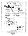
- Figure 2 illustrates a number of applications for relay stations.
- the coverage provided by a relay station may be "in-fill” to allow access to the communication network for mobile stations which may otherwise be in the shadow of other objects or otherwise unable to receive a signal of sufficient strength from the base station despite being within the normal range of the base station.
- Range extension is also shown, in which a relay station allows access when a mobile station is outside the normal data transmission range of a base station.
- in-fill shown at the top right of Figure 2 is positioning of a nomadic relay station to allow penetration of coverage within a building that could be above, at, or below ground level.
- Relays may also be used in conjunction with advanced transmission techniques to enhance gain of the communications system as explained below.
- pathloss propagation loss
- dB pathloss L
- d (metres) is the transmitter-receiver separation
- Multi-hop systems are suitable for use with multi-carrier transmission.
- a multi-carrier transmission system such as FDM (frequency division multiplex), OFDM (orthogonal frequency division multiplex) or DMT (discrete multi-tone)
- FDM frequency division multiplex
- OFDM orthogonal frequency division multiplex
- DMT discrete multi-tone
- a single data stream is modulated onto N parallel sub-carriers, each sub-carrier signal having its own frequency range. This allows the total bandwidth (i.e. the amount of data to be sent in a given time interval) to be divided over a plurality of sub-carriers thereby increasing the duration of each data symbol. Since each sub-carrier has a lower information rate, multi-carrier systems benefit from enhanced immunity to channel induced distortion compared with single carrier systems.
- the channel distortion correction entity within a multicarrier receiver can be of significantly lower complexity than its counterpart within a single carrier receiver when the system bandwidth is in excess of the coherence bandwidth of the channel.
- Orthogonal frequency division multiplexing is a modulation technique that is based on FDM.
- An OFDM system uses a plurality of sub-carrier frequencies which are orthogonal in a mathematical sense so that the sub-carriers' spectra may overlap without interference due to the fact they are mutually independent.
- the orthogonality of OFDM systems removes the need for guard band frequencies and thereby increases the spectral efficiency of the system.
- OFDM has been proposed and adopted for many wireless systems. It is currently used in Asymmetric Digital Subscriber Line (ADSL) connections, in some wireless LAN applications (such as WiFi devices based on the IEEE802.11a/g standard), and (of particular relevance to the present invention) in wireless MAN applications such as WiMAX (based on the IEEE 802.16 standard).
- ADSL Asymmetric Digital Subscriber Line
- OFDM is often used in conjunction with channel coding, an error correction technique, to create coded orthogonal FDM or COFDM.
- COFDM is now widely used in digital telecommunications systems to improve the performance of an OFDM based system in a multipath environment where variations in the channel distortion can be seen across both subcarriers in the frequency domain and symbols in the time domain.
- the system has found use in video and audio broadcasting, such as DVB and DAB, as well as certain types of computer networking technology.
- an OFDM symbol is the composite signal of all N sub-carrier signals.
- ⁇ f is the sub-carrier separation in Hz
- Ts 1/ ⁇ f is symbol time interval in seconds
- c n are the modulated source signals.
- DFT Discrete Fourier Transform
- FFT Fast Fourier Transform
- OFDMA Orthogonal Frequency Division Multiple Access
- FDD frequency division duplexing
- TDD time division duplexing
- Both approaches (TDD & FDD) have their relative merits and are both well used techniques for single hop wired and wireless communication systems.
- IEEE802.16 standard incorporates both an FDD and TDD mode. IEEE std 802.16-2004 "Air Interface for Fixed Broadband Wireless Access Systems" is hereby incorporated by reference in its entirety.
- Embodiments of the invention provide a communication method, communication system and intermediate apparatus (e.g., relay stations RS) employing a novel protocol adopted as a network entry procedure followed by the BS and RS, to enable entry of a legacy MS or SS into a relaying enabled communication network.
- the protocol involves decentralised control where the RS can manage the entire process.
- the protocol is based on an adaptation of the current network entry procedure followed in the IEEE802.16 standard and is specifically designed for the case when a RS transmits synchronisation and broadcast control information (i.e. preamble and MAP).
- the present invention also embraces computer software for executing the novel protocol on a RS, or on a MS/SS acting as an RS.
- legacy single hop systems e.g. 802.16-2004 and 802.16e-2005
- standard network entry procedures already exist to support entry of an MS or SS into a communication network.
- a modified network entry procedure is required from the network point of view to facilitate fast and efficient support of MS/SS network entry.
- This invention provides a protocol that is intended to be adopted as the modified network entry procedure from the network point of view, i.e. adopted in the RS and BS.
- it is designed with application to the IEEE802.16 standard in mind and requires no changes to the procedure from the MS or SS point of view.
- It is also designed for the case of non-transparent relaying where the RS is able to transmit a preamble and broadcast control information and hence has the capability to manage the process locally (i.e. distributed control) and hence minimise the latency that would otherwise be associated with relaying.
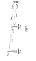
- Figure 3 illustrates the network entry procedure described in the IEEE802.16 standard which supports network entry of an MS or SS into a single-hop communication system.
- any RS with which the MS is communicating during the network entry procedure is already known to the network (incidentally, in this specification, the terms "network” and “system” are used interchangeably).
- the RS may have already completed entry into the network following a separate procedure, such as the one described in the applicant's UK application no. 0616475.0 , the disclosure of which is hereby incorporated by reference.
- the MS or SS still follows the same network entry procedure from its point of view, as illustrated in Figure 3 .
- the procedure followed by the RS is defined here and the one followed by the BS is modified from that followed for the case of a single hop network.
- a two-hop configuration as in Fig. 1 will be considered although the present invention is not limited to this.
- the MS/SS scans for preamble transmissions which may be originating from either BSs or RSs. Once all potential preambles are detected, the MS will select which channel it wishes to use from the available set of channels, in line with the standard procedure. It will then synchronise its receiver with the transmitter.
- the MS/SS obtains uplink parameters which includes location of the uplink control information transmission region that will be used by the MS/SS in the next stage. This information will be generated by the BS or RS that the MS/SS is attempting to connect to.
- the MS/SS will transmit a ranging code or ranging message, as defined in the IEEE802.16 standard, as a form of identification information to identify itself to the network.
- ranging message is more correct when OFDM is being used, and “ranging code” more appropriate to OFDMA, but in the following description "ranging code” is used for both). It is possible that a number of receivers in the multi-hop network receive this transmission. This code will be directed towards the preferred receiver based on the downlink channel selected.
- the receiver of the ranging code will then generally attempt to detect the ranging code independently as the RS appears like a BS to the MS. However, as it is likely that the RS will need to ensure that the BS and the BS to RS air interface can support this new connection, some mechanism will be needed within the system to facilitate this. Three alternative such mechanisms are:
- (100) indicates the first message sent to the RS (or BS) by the MS or SS that is attempting to enter the network through the RS. If the RS detects (100) then in the same frame (or at a later instant) it sends a message (200) to the BS to request any information that is required to support this process and also inform the BS of the arrival of (100). The RS will then respond to the MS/SS with an appropriate message (300) which could be for example a continue message and include information to the MS/SS such as adjustments to make to its next transmission. The BS will also respond to (200) to acknowledge and provide any of the requested information in (200), as shown with (400).
- an appropriate message 300
- the BS will also respond to (200) to acknowledge and provide any of the requested information in (200), as shown with (400).
- the MS/SS may transmit another message (500). If this is still not sufficient from the RS perspective it may respond with another continue and adjustment message such as (300). However, once it eventually receives a sufficient message (500) the RS will conclude the ranging process. At this point it will notify the BS with a message (600) and may also request information required for the following stages of network entry in another message (700). The RS will then inform the MS/SS of successful completion of the ranging process through another message (800).
- multiple RS may be interposed in the communication path between the MS/SS and BS.
- the above procedure is modified to include one RS receiving, and/or relaying, a ranging code or detection information from/to another RS, so that more than two process will occur in parallel, independently managed by the respective RS.
- the network could consist of some legacy BS (i.e., base stations operating in compliance with existing protocols) and some relaying enabled BS (i.e., base stations operating in accordance with the present invention). It is also assumed that a relaying enabled BS may be operating in a legacy mode until it receives a request from an RS for it to enter the network. The reason the BS may operate in such a mode would be to preserve transmission resources by not having to broadcast relay specific information when there are no relays benefiting from the transmission.
- the RS Once the RS has knowledge of the MS entering the network, it is possible for it to completely manage the remaining steps in the network entry process. It can then source information or inform the BS of the status of the procedure as and when required in such a way that the process between the RS and MS is optimised in terms of not introducing any extra latency.
- the RS can locally manage the authorisation process, informing the BS of the status, and sourcing any centrally held information as required from any centrally located servers that manage the authorisation within the network.
- the present invention can provide the following effects:
- an embodiment of the present invention can provide a transmission method for use in a wireless communication system, the system comprising a subscriber station, base station and intermediate apparatus in the form of one or more relay stations, the subscriber station and the base station being arranged to transmit and receive information via the intermediate apparatus, at least the subscriber station being required to perform a network entry process in order to connect to the system.
- the method comprises, in the intermediate apparatus, determining whether the subscriber station has initiated a network entry process with the intermediate apparatus, for example by receiving a ranging code from the subscriber station. Upon such a determination, the intermediate apparatus notifies the base station of the fact whilst continuing to conduct the network entry process with the subscriber station.
- the base station responds to this notification with a return message to the intermediate apparatus. This return message is part of a guidance process conducted from the base station to the intermediate apparatus so that the intermediate apparatus can manage completion of the network entry process.
- the method has particular relevance to multi-hop wireless systems based on standards such as IEEE802.16.
- Embodiments of the present invention may be implemented in hardware, or as software modules running on one or more processors, or on a combination thereof. That is, those skilled in the art will appreciate that a microprocessor or digital signal processor (DSP) may be used in practice to implement some or all of the functionality of a transmitter embodying the present invention.
- DSP digital signal processor
- the invention may also be embodied as one or more device or apparatus programs (e.g. computer programs and computer program products) for carrying out part or all of any of the methods described herein.
- Such programs embodying the present invention may be stored on computer-readable media, or could, for example, be in the form of one or more signals.
- Such signals may be data signals downloadable from an Internet website, or provided on a carrier signal, or in any other form.
- a program embodying the invention could also be used to add the functionality of the RS as described above to a MS/SS having suitable hardware.
Landscapes
- Engineering & Computer Science (AREA)
- Computer Networks & Wireless Communication (AREA)
- Signal Processing (AREA)
- Mobile Radio Communication Systems (AREA)
- Small-Scale Networks (AREA)
- Radio Relay Systems (AREA)
Abstract
Description
- Currently there exists significant interest in the use of multihop techniques in packet based radio and other communication systems, where it is purported that such techniques will enable both extension in coverage range and increase in system capacity (throughput).
- In a multi-hop communication system, communication signals are sent in a communication direction along a communication path from a source apparatus to a destination apparatus via one or more intermediate apparatuses.
Figure 1 illustrates a single-cell two-hop wireless communication system comprising a base station BS (known in the context of 3G communication systems as "node-B" NB), a relay node RN (also known as a relay station RS), and an item of user equipment UE (also known as a mobile station MS or subscriber station SS; below, the abbreviation MS or MS/SS is used to denote either of these types of UE). In the case where signals are being transmitted on the downlink (DL) from a base station to a destination user equipment (UE) via the relay node (RN), the base station comprises the source station (S) and the user equipment comprises the destination station (D). In the case where communication signals are being transmitted on the uplink (UL) from the user equipment (UE), via the relay node, to the base station, the user equipment comprises the source station and the base station comprises the destination station. The latter form of communication includes signals transmitted by the user equipment to identify itself to the base station (and hence to the network) as part of a network entry procedure. This is of particular relevance to the present invention as will be explained below. - The relay node is an example of intermediate apparatus and comprises: a receiver, operable to receive data from the source apparatus; and a transmitter, operable to transmit this data, or a derivative thereof, to the destination apparatus.
- Simple analogue repeaters or digital repeaters have been used as relays to improve or provide coverage in dead spots. They can either operate in a different transmission frequency band from the source station to prevent interference between the source transmission and the repeater transmission, or they can operate at a time when there is no transmission from the source station.
-
Figure 2 illustrates a number of applications for relay stations. For fixed infrastructure, the coverage provided by a relay station may be "in-fill" to allow access to the communication network for mobile stations which may otherwise be in the shadow of other objects or otherwise unable to receive a signal of sufficient strength from the base station despite being within the normal range of the base station. "Range extension" is also shown, in which a relay station allows access when a mobile station is outside the normal data transmission range of a base station. One example of in-fill shown at the top right ofFigure 2 is positioning of a nomadic relay station to allow penetration of coverage within a building that could be above, at, or below ground level. - Other applications are nomadic relay stations which are brought into effect for temporary cover, providing access during events or emergencies/disasters. A final application shown in the bottom right of
Figure 2 provides access to a network using a relay positioned on a vehicle. - Relays may also be used in conjunction with advanced transmission techniques to enhance gain of the communications system as explained below.
- It is known that the occurrence of propagation loss, or "pathloss", due to the scattering or absorption of a radio communication as it travels through space, causes the strength of a signal to diminish. Factors which influence the pathloss between a transmitter and a receiver include: transmitter antenna height, receiver antenna height, carrier frequency, clutter type (urban, sub-urban, rural), details of morphology such as height, density, separation, terrain type (hilly, flat). The pathloss L (dB) between a transmitter and a receiver can be modelled by:

- Where d (metres) is the transmitter-receiver separation, b(db) and n are the pathloss parameters and the absolute pathloss is given by l =10(L/10).
- The sum of the absolute path losses experienced over the indirect link Sl + ID may be less than the pathloss experienced over the direct link SD. In other words it is possible for:

- Splitting a single transmission link into two (or more) shorter transmission segments therefore exploits the non-linear relationship between pathloss verses distance. From a simple theoretical analysis of the pathloss using equation (A), it can be appreciated that a reduction in the overall pathloss (and therefore an improvement, or gain, in signal strength and thus data throughput) can be achieved if a signal is sent from a source apparatus to a destination apparatus via intermediate apparatus (one or more relay nodes), rather than being sent directly from the source apparatus to the destination apparatus. If implemented appropriately, multi-hop communication systems can allow for a reduction in the transmit power of transmitters which facilitate wireless transmissions, leading to a reduction in interference levels as well as decreasing exposure to electromagnetic emissions. Alternatively, the reduction in overall pathloss can be exploited to improve the received signal quality at the receiver without an increase in the overall radiated transmission power required to convey the signal.
- Multi-hop systems are suitable for use with multi-carrier transmission. In a multi-carrier transmission system, such as FDM (frequency division multiplex), OFDM (orthogonal frequency division multiplex) or DMT (discrete multi-tone), a single data stream is modulated onto N parallel sub-carriers, each sub-carrier signal having its own frequency range. This allows the total bandwidth (i.e. the amount of data to be sent in a given time interval) to be divided over a plurality of sub-carriers thereby increasing the duration of each data symbol. Since each sub-carrier has a lower information rate, multi-carrier systems benefit from enhanced immunity to channel induced distortion compared with single carrier systems. This is made possible by ensuring that the transmission rate and hence bandwidth of each subcarrier is less than the coherence bandwidth of the channel. As a result, the channel distortion experienced on a signal subcarrier is frequency independent and can hence be corrected by a simple phase and amplitude correction factor. Thus the channel distortion correction entity within a multicarrier receiver can be of significantly lower complexity than its counterpart within a single carrier receiver when the system bandwidth is in excess of the coherence bandwidth of the channel.
- Orthogonal frequency division multiplexing (OFDM) is a modulation technique that is based on FDM. An OFDM system uses a plurality of sub-carrier frequencies which are orthogonal in a mathematical sense so that the sub-carriers' spectra may overlap without interference due to the fact they are mutually independent. The orthogonality of OFDM systems removes the need for guard band frequencies and thereby increases the spectral efficiency of the system. OFDM has been proposed and adopted for many wireless systems. It is currently used in Asymmetric Digital Subscriber Line (ADSL) connections, in some wireless LAN applications (such as WiFi devices based on the IEEE802.11a/g standard), and (of particular relevance to the present invention) in wireless MAN applications such as WiMAX (based on the IEEE 802.16 standard). OFDM is often used in conjunction with channel coding, an error correction technique, to create coded orthogonal FDM or COFDM. COFDM is now widely used in digital telecommunications systems to improve the performance of an OFDM based system in a multipath environment where variations in the channel distortion can be seen across both subcarriers in the frequency domain and symbols in the time domain. The system has found use in video and audio broadcasting, such as DVB and DAB, as well as certain types of computer networking technology.
- In an OFDM system, a block of N modulated parallel data source signals is mapped to N orthogonal parallel sub-carriers by using an Inverse Discrete or Fast Fourier Transform algorithm (IDFT/IFFT) to form a signal known as an "OFDM symbol" in the time domain at the transmitter. Thus, an "OFDM symbol" is the composite signal of all N sub-carrier signals. An OFDM symbol can be represented mathematically as:

- OFDMA (Orthogonal Frequency Division Multiple Access) is a multiple access variant of OFDM. It works by assigning a subset of sub-carriers to an individual user. This allows simultaneous transmission from several users leading to better spectral efficiency. However, there is still the issue of allowing bi-directional communication, that is, in the uplink and download directions, without interference.
- In order to enable bi-directional communication between two nodes, two well known different approaches exist for duplexing the two (forward or download and reverse or uplink) communication links to overcome the physical limitation that a device cannot simultaneously transmit and receive on the same resource medium. The first, frequency division duplexing (FDD), involves operating the two links simultaneously but on different frequency bands by subdividing the transmission medium into two distinct bands, one for forward link and the other for reverse link communications. The second, time division duplexing (TDD), involves operating the two links on the same frequency band, but subdividing the access to the medium in time so that only the forward or the reverse link will be utilizing the medium at any one point in time. Both approaches (TDD & FDD) have their relative merits and are both well used techniques for single hop wired and wireless communication systems. For example the IEEE802.16 standard incorporates both an FDD and TDD mode. IEEE std 802.16-2004 "Air Interface for Fixed Broadband Wireless Access Systems" is hereby incorporated by reference in its entirety.
- In a single-hop communication system in which communication takes place directly between an MS/SS and a BS, a network entry procedure is followed by the MS/SS in conjunction with the BS. However, the known network entry procedure is not sufficient for a multi-hop system in which communication between the BS and MS/SS takes place via one or more relay stations RS. There is consequently a need for an improved network entry procedure applicable in such a case.
- The invention is defined in the independent claims, to which reference should now be made. Advantageous embodiments are set out in the sub claims.
- Embodiments of the invention provide a communication method, communication system and intermediate apparatus (e.g., relay stations RS) employing a novel protocol adopted as a network entry procedure followed by the BS and RS, to enable entry of a legacy MS or SS into a relaying enabled communication network. The protocol involves decentralised control where the RS can manage the entire process. The protocol is based on an adaptation of the current network entry procedure followed in the IEEE802.16 standard and is specifically designed for the case when a RS transmits synchronisation and broadcast control information (i.e. preamble and MAP).
- The present invention also embraces computer software for executing the novel protocol on a RS, or on a MS/SS acting as an RS.
- Preferred features of the present invention will now be described, by way of example, with reference to the accompanying drawings, in which:-
-
Figure 1 shows a single-cell two-hop wireless communication system; -
Figure 2 shows applications of relay stations RS; -
Figure 3 shows standard MS network entry procedure; and -
Figure 4 shows an RS management procedure during an MS ranging process in a relay enabled network, embodying the invention. - In legacy single hop systems (e.g. 802.16-2004 and 802.16e-2005), standard network entry procedures already exist to support entry of an MS or SS into a communication network. However, when the network is modified to support relaying functionality, of which a legacy MS or SS has no knowledge, a modified network entry procedure is required from the network point of view to facilitate fast and efficient support of MS/SS network entry.
- This invention provides a protocol that is intended to be adopted as the modified network entry procedure from the network point of view, i.e. adopted in the RS and BS. In particular it is designed with application to the IEEE802.16 standard in mind and requires no changes to the procedure from the MS or SS point of view. It is also designed for the case of non-transparent relaying where the RS is able to transmit a preamble and broadcast control information and hence has the capability to manage the process locally (i.e. distributed control) and hence minimise the latency that would otherwise be associated with relaying.
-
Figure 3 illustrates the network entry procedure described in the IEEE802.16 standard which supports network entry of an MS or SS into a single-hop communication system. - Here, it is assumed that any RS with which the MS is communicating during the network entry procedure is already known to the network (incidentally, in this specification, the terms "network" and "system" are used interchangeably). For example, the RS may have already completed entry into the network following a separate procedure, such as the one described in the applicant's
UK application no. 0616475.0 Figure 3 . However, the procedure followed by the RS is defined here and the one followed by the BS is modified from that followed for the case of a single hop network. For ease of explanation, a two-hop configuration as inFig. 1 will be considered although the present invention is not limited to this. - During this stage the MS/SS scans for preamble transmissions which may be originating from either BSs or RSs. Once all potential preambles are detected, the MS will select which channel it wishes to use from the available set of channels, in line with the standard procedure. It will then synchronise its receiver with the transmitter.
- Note that no additional operations are required beyond those in the existing single hop system.
- During this stage the MS/SS obtains uplink parameters which includes location of the uplink control information transmission region that will be used by the MS/SS in the next stage. This information will be generated by the BS or RS that the MS/SS is attempting to connect to.
- The MS/SS will transmit a ranging code or ranging message, as defined in the IEEE802.16 standard, as a form of identification information to identify itself to the network. (incidentally, the term "ranging message" is more correct when OFDM is being used, and "ranging code" more appropriate to OFDMA, but in the following description "ranging code" is used for both). It is possible that a number of receivers in the multi-hop network receive this transmission. This code will be directed towards the preferred receiver based on the downlink channel selected.
- The receiver of the ranging code will then generally attempt to detect the ranging code independently as the RS appears like a BS to the MS. However, as it is likely that the RS will need to ensure that the BS and the BS to RS air interface can support this new connection, some mechanism will be needed within the system to facilitate this. Three alternative such mechanisms are:
- 1. The ranging request is relayed back to the BS from the RS, setting the transmission power accordingly; or the detection is performed in RS but detection information is relayed to the BS. However, due to the frame structure associated with this type of system and the fact that any response messages are required to come via the RS, both of these approaches will incur extra latency from the view point of the MS/SS. Hence this method is not preferred for a performance point of view, however it keeps the complexity to a minimum in the RS so is advantageous in this sense.
- 2. The BS informs the RS of a detection threshold and the RS manages the ranging process until the threshold is met, generating any feedback information locally. However, the final ranging response with the completion method still has to be relayed from the BS, incur some extra latency. This method provides a lower latency solution with the requirements of increased complexity when compared with the mechanism proposed in 1.
- 3. (embodiment of the present invention): The RS completely manages the ranging process locally. However, to ensure that the BS can support the connection, as soon as it has knowledge of the MS attempting to enter the network through detecting the ranging code for the first time, it then informs the BS that a user is attempting network entry. Whilst the RS manages the ranging process, it effectively pipelines in parallel a second "ranging process" relating to this connection over the RS to BS link, thereby minimising latency. This second "ranging process" is a process conducted by the RS with the BS on behalf of the MS, and does not require a ranging code of its own. The BS will then inform the RS whether the connection can be supported, and also inform the RS of any specific information regarding the connection type, service level, etc that can be offered over the composite link. The RS can then interpret the information, passing on any relevant elements to the MS/SS, or use it to determine whether to continue with the ranging process. The RS may also request specific information from the BS that it will require to include in its successful ranging or any continue ranging message. This third mechanism is preferred in terms of network performance due to the fact it provides highest efficiency by running the ranging and network entry process over the two links independently, however it requires greatest complexity in the RS.
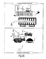
- The procedure described in paragraph 3 is illustrated in
Figure 4 . Here, (100) indicates the first message sent to the RS (or BS) by the MS or SS that is attempting to enter the network through the RS. If the RS detects (100) then in the same frame (or at a later instant) it sends a message (200) to the BS to request any information that is required to support this process and also inform the BS of the arrival of (100). The RS will then respond to the MS/SS with an appropriate message (300) which could be for example a continue message and include information to the MS/SS such as adjustments to make to its next transmission. The BS will also respond to (200) to acknowledge and provide any of the requested information in (200), as shown with (400). - At some point later in time the MS/SS may transmit another message (500). If this is still not sufficient from the RS perspective it may respond with another continue and adjustment message such as (300). However, once it eventually receives a sufficient message (500) the RS will conclude the ranging process. At this point it will notify the BS with a message (600) and may also request information required for the following stages of network entry in another message (700). The RS will then inform the MS/SS of successful completion of the ranging process through another message (800).
- Note that in the case the first transmission from the MS/SS (100) is sufficient from the RS point of view then the messages between the RS and BS will still be exchanged (i.e. (200)(400)(600)(700)), however the RS and MS will obviously skip messages (300) and (500).
- Alternatively, in a multi-hop configuration, multiple RS may be interposed in the communication path between the MS/SS and BS. In such a case, the above procedure is modified to include one RS receiving, and/or relaying, a ranging code or detection information from/to another RS, so that more than two process will occur in parallel, independently managed by the respective RS.
- In the above description, it is assumed that the network could consist of some legacy BS (i.e., base stations operating in compliance with existing protocols) and some relaying enabled BS (i.e., base stations operating in accordance with the present invention). It is also assumed that a relaying enabled BS may be operating in a legacy mode until it receives a request from an RS for it to enter the network. The reason the BS may operate in such a mode would be to preserve transmission resources by not having to broadcast relay specific information when there are no relays benefiting from the transmission.
- Once the RS has knowledge of the MS entering the network, it is possible for it to completely manage the remaining steps in the network entry process. It can then source information or inform the BS of the status of the procedure as and when required in such a way that the process between the RS and MS is optimised in terms of not introducing any extra latency.
- For example, assuming that the RS has undergone authorisation with the BS, the RS can locally manage the authorisation process, informing the BS of the status, and sourcing any centrally held information as required from any centrally located servers that manage the authorisation within the network.
- As described above, the present invention can provide the following effects:
- o Defines a ranging and network entry procedure that effectively consists of two or more (depending on number of links) processes occurring in parallel and independently managed by the RS to which the connection is being sought;
- o Minimises the latency that would be associated with network entry due to the local management of the process;
- o Provides a scalable solution that enables a system to support potentially a large number of hops with no significant or, at worst, limited impact on network entry performance.
- Thus, an embodiment of the present invention can provide a transmission method for use in a wireless communication system, the system comprising a subscriber station, base station and intermediate apparatus in the form of one or more relay stations, the subscriber station and the base station being arranged to transmit and receive information via the intermediate apparatus, at least the subscriber station being required to perform a network entry process in order to connect to the system. The method comprises, in the intermediate apparatus, determining whether the subscriber station has initiated a network entry process with the intermediate apparatus, for example by receiving a ranging code from the subscriber station. Upon such a determination, the intermediate apparatus notifies the base station of the fact whilst continuing to conduct the network entry process with the subscriber station. The base station responds to this notification with a return message to the intermediate apparatus. This return message is part of a guidance process conducted from the base station to the intermediate apparatus so that the intermediate apparatus can manage completion of the network entry process. The method has particular relevance to multi-hop wireless systems based on standards such as IEEE802.16.
- Embodiments of the present invention may be implemented in hardware, or as software modules running on one or more processors, or on a combination thereof. That is, those skilled in the art will appreciate that a microprocessor or digital signal processor (DSP) may be used in practice to implement some or all of the functionality of a transmitter embodying the present invention. The invention may also be embodied as one or more device or apparatus programs (e.g. computer programs and computer program products) for carrying out part or all of any of the methods described herein. Such programs embodying the present invention may be stored on computer-readable media, or could, for example, be in the form of one or more signals. Such signals may be data signals downloadable from an Internet website, or provided on a carrier signal, or in any other form.
- A program embodying the invention could also be used to add the functionality of the RS as described above to a MS/SS having suitable hardware.
Claims (14)
- A transmission method for use in a wireless communication system, the system comprising a source apparatus, a destination apparatus and an intermediate apparatus, the source apparatus and destination apparatus being arranged to transmit and receive information via the intermediate apparatus, at least the source apparatus being arranged to perform a network entry process in order to connect to the system, the method comprising:in the intermediate apparatus, detecting a ranging code transmitted from the source station, transmitting a request for information to support the network entry process to the destination apparatus, receiving the information in a return message from the destination station and transmitting a message indicating continuation and/or adjustment information to the source station to conduct the network entry process.
- The transmission method according to claim 1, wherein following a successful detection of said ranging code, said intermediate apparatus manages the rest of the network entry process with the source apparatus.
- The transmission method according to claim 1 or 2 wherein said notification from the intermediate apparatus to the destination apparatus is part of a guidance process for network entry of the source apparatus, conducted between the destination apparatus and the intermediate apparatus in parallel with, and independently from, said network entry process conducted by the intermediate apparatus with the source apparatus.
- The transmission method according to any preceding claim wherein said return message from the destination apparatus to the intermediate apparatus informs the intermediate apparatus of whether the connection can be supported.
- The transmission method according to any preceding claim, wherein said return message from the destination apparatus to the intermediate apparatus informs the intermediate apparatus of a connection type and/or service level available to the source apparatus via the intermediate apparatus.
- The transmission method according to claim 5 wherein the intermediate apparatus uses said return message to determine whether to continue with the network entry process.
- The transmission method according to any preceding claim, wherein the source apparatus is a subscriber station and the destination apparatus is a base station.
- The transmission method according to any preceding claim, wherein the intermediate apparatus is a relay station arranged in a two-hop configuration between the source apparatus and the destination apparatus.
- The transmission method according to any of claims 1 to 7, wherein the intermediate apparatus is constituted by a plurality of relay stations arranged in a multi-hop configuration between the source apparatus and the destination apparatus, a first of the relay stations detecting the initiation of the network entry process by the source apparatus and relaying said notification to another of the relay stations for forwarding to the destination apparatus.
- A wireless communication system comprising a source apparatus, a destination apparatus and an intermediate apparatus, the source apparatus and destination apparatus being arranged to transmit and receive information via the intermediate apparatus, at least the source apparatus being arranged to perform a network entry process in order to connect to the system, wherein:the intermediate apparatus is arranged for detecting a ranging code transmitted from the source station, transmitting a request for information to support the network entry process to the destination apparatus, receiving the information in a return message from the destination station and transmitting a message indicating continuation and/or adjustment information to the source station to conduct the network entry process; andthe destination apparatus includes means for responding to said request with said return message to the intermediate apparatus, said return message being used by said managing means to facilitate completion of the network entry process.
- Intermediate apparatus for use in a wireless communication system, the system having a source apparatus and a destination apparatus arranged to transmit and receive information via the intermediate apparatus, the system requiring at least the source apparatus to perform a network entry process in order to connect to the system, wherein the intermediate apparatus includes:means for detecting a ranging code transmitted from the source station,means for transmitting a request for information to support the network entry process to the destination apparatus,means for receiving the information in a return message from the destination station, andmeans for transmitting a message indicating continuation and/or adjustment information to the source station to conduct the network entry process.
- Intermediate apparatus according to claim 11 in the form of a single relay station for use in a two-hop configuration with the source apparatus and the destination apparatus.
- Intermediate apparatus according to claim 11 in the form of a plurality of relay stations for use in a multi-hop configuration between the source apparatus and the destination apparatus, each relay station including said determining means, said notifying means, and said managing means,
said notifying means also being responsive to a notification from another one of the relay stations, and arranged to notify either the destination apparatus, or an upstream relay station if any, of the network entry process being initiated by the source apparatus; and
said managing means also being responsive from a reply received via the upstream relay station if any, either to complete the network entry process with the source apparatus by using information contained in said reply or to forward said information to a downstream relay station if any. - A computer program which, when executed by intermediate apparatus in a wireless communication system having a subscriber station and a base station each arranged to transmit and receive information via the intermediate apparatus and requiring at least the subscriber station to perform a network entry process in order to connect to the system, provides the intermediate apparatus with the functions of:detecting a ranging code transmitted from the source station, transmitting a request for information to support the network entry process to the destination apparatus, receiving the information in a return message from the destination station and transmitting a message indicating continuation and/or adjustment information to the source station to conduct the network entry process.
Applications Claiming Priority (2)
| Application Number | Priority Date | Filing Date | Title |
|---|---|---|---|
| GB0617752A GB2441574A (en) | 2006-09-08 | 2006-09-08 | Network entry to a multi-hop wireless communication system |
| EP07113483A EP1898561B1 (en) | 2006-09-08 | 2007-07-31 | Decentralised control of network entry in a multihop relay mobile communication system |
Related Parent Applications (2)
| Application Number | Title | Priority Date | Filing Date |
|---|---|---|---|
| EP07113483.7 Division | 2007-07-31 | ||
| EP07113483A Division EP1898561B1 (en) | 2006-09-08 | 2007-07-31 | Decentralised control of network entry in a multihop relay mobile communication system |
Publications (2)
| Publication Number | Publication Date |
|---|---|
| EP1968259A1 true EP1968259A1 (en) | 2008-09-10 |
| EP1968259B1 EP1968259B1 (en) | 2011-09-14 |
Family
ID=37232647
Family Applications (3)
| Application Number | Title | Priority Date | Filing Date |
|---|---|---|---|
| EP09173115A Ceased EP2139173B1 (en) | 2006-09-08 | 2007-07-31 | Decentralised control of network entry in a multihop relay mobile communication system |
| EP08155435A Ceased EP1968259B1 (en) | 2006-09-08 | 2007-07-31 | Decentralised control of network entry in a multihop relay mobile communication system |
| EP07113483A Ceased EP1898561B1 (en) | 2006-09-08 | 2007-07-31 | Decentralised control of network entry in a multihop relay mobile communication system |
Family Applications Before (1)
| Application Number | Title | Priority Date | Filing Date |
|---|---|---|---|
| EP09173115A Ceased EP2139173B1 (en) | 2006-09-08 | 2007-07-31 | Decentralised control of network entry in a multihop relay mobile communication system |
Family Applications After (1)
| Application Number | Title | Priority Date | Filing Date |
|---|---|---|---|
| EP07113483A Ceased EP1898561B1 (en) | 2006-09-08 | 2007-07-31 | Decentralised control of network entry in a multihop relay mobile communication system |
Country Status (7)
| Country | Link |
|---|---|
| US (2) | US9559769B2 (en) |
| EP (3) | EP2139173B1 (en) |
| JP (2) | JP5040535B2 (en) |
| KR (1) | KR100927308B1 (en) |
| CN (2) | CN101141808B (en) |
| GB (1) | GB2441574A (en) |
| TW (2) | TWI357736B (en) |
Cited By (2)
| Publication number | Priority date | Publication date | Assignee | Title |
|---|---|---|---|---|
| CN102640546A (en) * | 2009-11-10 | 2012-08-15 | 夏普株式会社 | Wireless communication system, base station device, mobile station device, and wireless communication method |
| CN111343123A (en) * | 2020-02-28 | 2020-06-26 | 广西华南通信股份有限公司 | Orthogonal frequency division multiplexing dynamic coding method for multi-hop cooperative network communication |
Families Citing this family (9)
| Publication number | Priority date | Publication date | Assignee | Title |
|---|---|---|---|---|
| DE602008002707D1 (en) * | 2008-03-27 | 2010-11-04 | Fujitsu Ltd | Wireless communication systems |
| US8369241B2 (en) * | 2008-05-05 | 2013-02-05 | Mediatek Inc. | Fast feedback contention-based ranging procedure in wireless communications systems |
| US20100111029A1 (en) * | 2008-05-05 | 2010-05-06 | Mediatek Inc. | Fast feedback contention-based data transmission in wireless communications systems |
| KR20110044892A (en) | 2008-08-27 | 2011-05-02 | 교세라 가부시키가이샤 | Radio relay station, radio relay method, radio communication system, location management device, radio terminal and radio communication method |
| WO2010023847A1 (en) | 2008-08-28 | 2010-03-04 | 京セラ株式会社 | Repeater, communication system, base station, radio terminal, and management server |
| JP4980321B2 (en) | 2008-09-16 | 2012-07-18 | 京セラ株式会社 | Radio relay apparatus and radio relay method |
| US8279991B2 (en) * | 2008-10-03 | 2012-10-02 | Motorola Solutions, Inc. | Method of efficiently synchronizing to a desired timeslot in a time division multiple access communication system |
| JP5342294B2 (en) | 2009-03-26 | 2013-11-13 | 京セラ株式会社 | Radio relay station and radio relay method |
| GB2475906A (en) * | 2009-12-04 | 2011-06-08 | Sharp Kk | A relay apparatus used in connection with the lte-a standard |
Citations (2)
| Publication number | Priority date | Publication date | Assignee | Title |
|---|---|---|---|---|
| GB616475A (en) | 1946-09-05 | 1949-01-21 | Alfred Hamer | Improvements in and relating to closure devices for barrels and other containers |
| US20050048914A1 (en) * | 2003-09-03 | 2005-03-03 | Motorola, Inc. | Method and apparatus for relay facilitated communications |
Family Cites Families (69)
| Publication number | Priority date | Publication date | Assignee | Title |
|---|---|---|---|---|
| DE3403715A1 (en) | 1984-02-03 | 1985-08-08 | Licentia Patent-Verwaltungs-Gmbh, 6000 Frankfurt | DIGITAL CELL RADIO SYSTEM WITH TIME MULTIPLEX |
| US5719868A (en) | 1995-10-05 | 1998-02-17 | Rockwell International | Dynamic distributed, multi-channel time division multiple access slot assignment method for a network of nodes |
| US6236647B1 (en) | 1998-02-24 | 2001-05-22 | Tantivy Communications, Inc. | Dynamic frame size adjustment and selective reject on a multi-link channel to improve effective throughput and bit error rate |
| US6370384B1 (en) | 1998-07-30 | 2002-04-09 | Airnet Communications Corporation | Frequency re-use planning for wireless communications system using wireless translating repeaters |
| US7006530B2 (en) | 2000-12-22 | 2006-02-28 | Wi-Lan, Inc. | Method and system for adaptively obtaining bandwidth allocation requests |
| US7158784B1 (en) | 2000-03-31 | 2007-01-02 | Aperto Networks, Inc. | Robust topology wireless communication using broadband access points |
| US6701129B1 (en) | 2000-09-27 | 2004-03-02 | Nortel Networks Limited | Receiver based adaptive modulation scheme |
| DE60117202D1 (en) | 2001-09-03 | 2006-04-20 | St Microelectronics Nv | A method and apparatus for estimating the speed of a mobile terminal in a wireless communication system |
| GB0200237D0 (en) | 2002-01-07 | 2002-02-20 | Imec Inter Uni Micro Electr | Wireless cellular network architecture |
| US7096274B1 (en) | 2002-02-12 | 2006-08-22 | 3Com Corporation | Optimum frame size predictor for wireless Local Area Network |
| US7577399B2 (en) * | 2002-06-21 | 2009-08-18 | Nokia Siemens Networks Gmbh & Co. Kg | Method and communication station for transmitting data |
| JP2004040568A (en) | 2002-07-04 | 2004-02-05 | Denso Corp | Radio communications terminal |
| US7580394B2 (en) | 2002-11-27 | 2009-08-25 | Nokia Corporation | System and method for collision-free transmission scheduling in a network |
| US20040109428A1 (en) | 2002-12-09 | 2004-06-10 | Srikanth Krishnamurthy | Method and apparatus for resource allocation for multiple traffic classes in wireless ad-hoc networks |
| US7583619B2 (en) | 2002-12-16 | 2009-09-01 | Nortel Networks Limited | Wireless access communications network |
| KR100483007B1 (en) * | 2002-12-24 | 2005-04-18 | 한국전자통신연구원 | Method of handover in next generation mobile telecommunication system |
| JP3838363B2 (en) * | 2003-03-17 | 2006-10-25 | Kddi株式会社 | Mobile network and communication method thereof |
| CN100531167C (en) | 2003-05-28 | 2009-08-19 | 艾利森电话股份有限公司 | Method and system for wireless communication networks using relaying |
| KR100769741B1 (en) * | 2003-05-29 | 2007-10-23 | 교세라 가부시키가이샤 | Radio communication system, radio communication apparatus, radio communication terminal and mobile radio communication apparatus |
| US7903538B2 (en) | 2003-08-06 | 2011-03-08 | Intel Corporation | Technique to select transmission parameters |
| US7974227B1 (en) * | 2003-12-02 | 2011-07-05 | Thomas Stanley Seay | Relayed signal communications |
| AU2003298477B2 (en) | 2003-12-30 | 2008-10-02 | Nokia Technologies Oy | Communication system using relay base stations with asymmetric data links |
| JP2006033207A (en) | 2004-07-14 | 2006-02-02 | Nec Corp | Position information providing system, radio base station device, position information providing method used for both, and program thereof |
| DE112005001761T5 (en) | 2004-07-23 | 2007-05-24 | Wireless Valley Communications, Inc., Austin | A system, method and apparatus for determining and using a location of wireless devices or a wireless network enhancement infrastructure |
| CN1333615C (en) * | 2004-07-23 | 2007-08-22 | 北京邮电大学 | Relay selecting and power distribution method for double bounce honeycomb system |
| US7864659B2 (en) | 2004-08-02 | 2011-01-04 | Interdigital Technology Corporation | Quality control scheme for multiple-input multiple-output (MIMO) orthogonal frequency division multiplexing (OFDM) systems |
| JP2006047912A (en) | 2004-08-09 | 2006-02-16 | Olympus Corp | Super-resolution microscope |
| EP1635592B1 (en) | 2004-09-13 | 2007-05-23 | Alcatel Lucent | Estimation of channel quality for wireless communication network |
| KR100810290B1 (en) | 2004-12-14 | 2008-03-07 | 삼성전자주식회사 | Method and system for allocation data burst in a wireless communication system |
| KR100584409B1 (en) | 2004-12-29 | 2006-05-26 | 삼성전자주식회사 | Relay commonication method for ofdma-based cellular communication system |
| US8644130B2 (en) | 2005-03-18 | 2014-02-04 | Samsung Electronics Co., Ltd. | System and method for subcarrier allocation in a wireless multihop relay network |
| US7486928B2 (en) * | 2005-04-14 | 2009-02-03 | Kddi Corporation | Methods and apparatus for wireless communications |
| JP4137083B2 (en) * | 2005-04-19 | 2008-08-20 | Kddi株式会社 | Wireless data communication method and system |
| US7813695B2 (en) | 2005-05-06 | 2010-10-12 | Telefonaktiebolaget L M Ericsson (Publ) | Mobile assisted relay selection in a telecommunications system |
| JP2006319676A (en) | 2005-05-12 | 2006-11-24 | Oki Electric Ind Co Ltd | Frame transmitting method, topology acquiring method and radio communication system |
| KR20070004370A (en) | 2005-07-04 | 2007-01-09 | 삼성전자주식회사 | Cooperative relay transmission technique for wireless communication system |
| US8554232B2 (en) * | 2005-08-17 | 2013-10-08 | Apple Inc. | Method and system for a wireless multi-hop relay network |
| WO2007053948A1 (en) * | 2005-11-10 | 2007-05-18 | Nortel Networks Limited | Wireless relay network media access control layer control plane system and method |
| WO2007053949A1 (en) * | 2005-11-12 | 2007-05-18 | Nortel Networks Limited | System and method for unbalanced relay-based wireless communications |
| WO2007053950A1 (en) * | 2005-11-12 | 2007-05-18 | Nortel Networks Limited | Media access control data plane system and method for wireless communication networks |
| US8009645B2 (en) | 2006-01-03 | 2011-08-30 | Samsung Electronics., Ltd. | Method for requesting and allocating upstream bandwidth in a multi-hop relay broadband wireless access communication system |
| US7599341B2 (en) | 2006-02-28 | 2009-10-06 | Motorola, Inc. | System and method for managing communication routing within a wireless multi-hop network |
| US8300570B2 (en) * | 2006-06-02 | 2012-10-30 | Research In Motion Limited | Ranging regions for wireless communication relay stations |
| US8514822B2 (en) * | 2006-06-14 | 2013-08-20 | Zte (Usa) Inc. | Efficient acknowledgement messaging in wireless communications |
| RU2009102013A (en) * | 2006-06-30 | 2010-08-10 | Нокиа Коропрейшн (FI) | REPEATER |
| US20080002741A1 (en) * | 2006-06-30 | 2008-01-03 | Nokia Corporation | Apparatus, method and computer program product providing optimized location update for mobile station in a relay-based network |
| US8126470B2 (en) * | 2006-07-03 | 2012-02-28 | Nokia Corporation | Topology and route discovery and management for relay networks |
| EP2041910A4 (en) * | 2006-07-06 | 2013-05-22 | Apple Inc | Wireless access point security for multi-hop networks |
| WO2008011718A1 (en) * | 2006-07-28 | 2008-01-31 | Nortel Networks Limited | System and method for wireless multi-hop network synchronization and monitoring |
| US7773941B2 (en) * | 2006-07-31 | 2010-08-10 | Motorola, Inc. | Method and system for positioning a relay in a wide area communication network |
| US8055189B2 (en) * | 2006-08-03 | 2011-11-08 | Institute For Information Industry | Wireless communication system, method, and tangible machine-readable medium thereof for transmitting data based on a frame structure of a multi-hop relay standard |
| US20080031180A1 (en) * | 2006-08-03 | 2008-02-07 | Institute For Information Industry | Frame structure, wireless communication apparatus, and method for assigning the same |
| US8165073B2 (en) * | 2006-08-04 | 2012-04-24 | Nokia Corporation | Relay-station assignment/re-assignment and frequency re-use |
| US8644287B2 (en) * | 2006-08-09 | 2014-02-04 | Institute For Information Industry | Wireless communication system, apparatus, and method for transmitting information to describe network topology |
| US8107408B2 (en) * | 2006-08-09 | 2012-01-31 | Nokia Siemens Networks Gmbh & Co. Kg | Route maintenance and update based on connection identifier in multi-hop relay systems |
| GB2440985A (en) * | 2006-08-18 | 2008-02-20 | Fujitsu Ltd | Wireless multi-hop communication system |
| CN101127686B (en) * | 2006-08-18 | 2012-04-04 | 华为技术有限公司 | A network data processing method and device |
| GB2440986A (en) * | 2006-08-18 | 2008-02-20 | Fujitsu Ltd | Wireless multi-hop communication system |
| GB2440981A (en) * | 2006-08-18 | 2008-02-20 | Fujitsu Ltd | Wireless multi-hop communication system |
| GB2440980A (en) * | 2006-08-18 | 2008-02-20 | Fujitsu Ltd | Wireless multi-hop communication system |
| GB2440984A (en) * | 2006-08-18 | 2008-02-20 | Fujitsu Ltd | Wireless multi-hop communication system |
| GB2440982A (en) * | 2006-08-18 | 2008-02-20 | Fujitsu Ltd | Wireless multi-hop communication system |
| GB0616472D0 (en) * | 2006-08-18 | 2006-09-27 | Fujitsu Ltd | Communication systems |
| US20080049678A1 (en) * | 2006-08-24 | 2008-02-28 | Siemens Corporate Research, Inc. | Relay-Assisted Channel Condition Measurements For Connection Setup and Maintenance |
| JP2008085082A (en) * | 2006-09-27 | 2008-04-10 | Sony Corp | Power mosfet, semiconductor device equipped with the same, and manufacturing method of power mosfet |
| GB2442782A (en) * | 2006-10-13 | 2008-04-16 | Fujitsu Ltd | Wireless communication systems |
| GB2442783A (en) * | 2006-10-13 | 2008-04-16 | Fujitsu Ltd | Wireless communication systems |
| GB2443465A (en) * | 2006-11-06 | 2008-05-07 | Fujitsu Ltd | Communication systems |
| US7934547B2 (en) * | 2007-08-17 | 2011-05-03 | Schlumberger Technology Corporation | Apparatus and methods to control fluid flow in a downhole tool |
-
2006
- 2006-09-08 GB GB0617752A patent/GB2441574A/en not_active Withdrawn
-
2007
- 2007-07-31 EP EP09173115A patent/EP2139173B1/en not_active Ceased
- 2007-07-31 EP EP08155435A patent/EP1968259B1/en not_active Ceased
- 2007-07-31 TW TW096127990A patent/TWI357736B/en not_active IP Right Cessation
- 2007-07-31 EP EP07113483A patent/EP1898561B1/en not_active Ceased
- 2007-07-31 TW TW098141520A patent/TWI424701B/en not_active IP Right Cessation
- 2007-09-03 JP JP2007228359A patent/JP5040535B2/en not_active Expired - Fee Related
- 2007-09-05 KR KR1020070090107A patent/KR100927308B1/en not_active IP Right Cessation
- 2007-09-06 CN CN200710149198XA patent/CN101141808B/en not_active Expired - Fee Related
- 2007-09-06 CN CN200910224591.XA patent/CN101730116B/en not_active Expired - Fee Related
- 2007-09-07 US US11/851,430 patent/US9559769B2/en active Active
-
2009
- 2009-10-27 US US12/606,753 patent/US20100105397A1/en not_active Abandoned
-
2010
- 2010-05-25 JP JP2010119396A patent/JP5041033B2/en not_active Expired - Fee Related
Patent Citations (2)
| Publication number | Priority date | Publication date | Assignee | Title |
|---|---|---|---|---|
| GB616475A (en) | 1946-09-05 | 1949-01-21 | Alfred Hamer | Improvements in and relating to closure devices for barrels and other containers |
| US20050048914A1 (en) * | 2003-09-03 | 2005-03-03 | Motorola, Inc. | Method and apparatus for relay facilitated communications |
Non-Patent Citations (4)
| Title |
|---|
| IEEE COMPUTER SOCIETY: "IEEE Standard for Local and metropolitan area networks; Part 16: Air Interface for Fixed Broadband Wireless Access Systems - Amendment 2: Medium Access Control Modifications and Additional Physical Layer Specifications for 2-11 GHz; IEEE Std 802.16a-2003", 1 April 2003 (2003-04-01), pages 1,19,68-70,80-87, XP002490686, Retrieved from the Internet <URL:http://info.awmn.net/users/images/stories/Library/802.16/802.16a-2003.pdf> [retrieved on 20080801] * |
| MIKE HART ET AL.: "Fujitsu Laboratories of Europe", IEEE C802.16MMR-05/017R1, 13 September 2005 (2005-09-13), pages 1 - 19 |
| MIKE HART ET AL: "Factors that affect performance of a mobile multihop relay system", INTERNET CITATION, 13 September 2005 (2005-09-13), pages 1 - 19, XP002419888, Retrieved from the Internet <URL:http://www..ieee802org/16/sg/nmr/contrib/> [retrieved on 20070213] * |
| RELAY TASK GROUP OF IEEE 802.16: "PART 16: AIR INTERFACE FOR FIXED AND MOBILE BROADBAND WIRELESS ACCESS SYSTEMS", P802.16J BASELINE DOCUMENT FOR DRAFT STANDARD, 6 June 2007 (2007-06-06), pages I-XII,78-104, XP002452638, Retrieved from the Internet <URL:http://ieee802.org/16/relay/docs/80216j-06_026r4.zip> [retrieved on 20070926] * |
Cited By (3)
| Publication number | Priority date | Publication date | Assignee | Title |
|---|---|---|---|---|
| CN102640546A (en) * | 2009-11-10 | 2012-08-15 | 夏普株式会社 | Wireless communication system, base station device, mobile station device, and wireless communication method |
| CN111343123A (en) * | 2020-02-28 | 2020-06-26 | 广西华南通信股份有限公司 | Orthogonal frequency division multiplexing dynamic coding method for multi-hop cooperative network communication |
| CN111343123B (en) * | 2020-02-28 | 2023-03-14 | 广西华南通信股份有限公司 | Orthogonal frequency division multiplexing dynamic coding method for multi-hop cooperative network communication |
Also Published As
| Publication number | Publication date |
|---|---|
| US9559769B2 (en) | 2017-01-31 |
| JP5040535B2 (en) | 2012-10-03 |
| US20100105397A1 (en) | 2010-04-29 |
| TW201015901A (en) | 2010-04-16 |
| US20080062908A1 (en) | 2008-03-13 |
| EP1968259B1 (en) | 2011-09-14 |
| TW200816695A (en) | 2008-04-01 |
| EP2139173A2 (en) | 2009-12-30 |
| CN101730116A (en) | 2010-06-09 |
| CN101730116B (en) | 2014-05-07 |
| EP1898561A1 (en) | 2008-03-12 |
| KR20080023149A (en) | 2008-03-12 |
| KR100927308B1 (en) | 2009-11-18 |
| CN101141808B (en) | 2012-03-07 |
| CN101141808A (en) | 2008-03-12 |
| TWI357736B (en) | 2012-02-01 |
| EP2139173A3 (en) | 2010-07-14 |
| JP2010200375A (en) | 2010-09-09 |
| JP5041033B2 (en) | 2012-10-03 |
| EP2139173B1 (en) | 2011-09-21 |
| EP1898561B1 (en) | 2011-09-14 |
| GB2441574A (en) | 2008-03-12 |
| TWI424701B (en) | 2014-01-21 |
| GB0617752D0 (en) | 2006-10-18 |
| JP2008067386A (en) | 2008-03-21 |
Similar Documents
| Publication | Publication Date | Title |
|---|---|---|
| EP1968259B1 (en) | Decentralised control of network entry in a multihop relay mobile communication system | |
| EP2178325B1 (en) | Multi-hop wireless communication | |
| US7957257B2 (en) | Communication systems | |
| US7970347B2 (en) | Communication systems | |
| KR100966690B1 (en) | Communication systems | |
| US20090245162A1 (en) | Communication Systems |
Legal Events
| Date | Code | Title | Description |
|---|---|---|---|
| PUAI | Public reference made under article 153(3) epc to a published international application that has entered the european phase |
Free format text: ORIGINAL CODE: 0009012 |
|
| AC | Divisional application: reference to earlier application |
Ref document number: 1898561 Country of ref document: EP Kind code of ref document: P |
|
| AK | Designated contracting states |
Kind code of ref document: A1 Designated state(s): DE FR GB IT |
|
| 17P | Request for examination filed |
Effective date: 20090304 |
|
| 17Q | First examination report despatched |
Effective date: 20090403 |
|
| AKX | Designation fees paid |
Designated state(s): DE FR GB IT |
|
| REG | Reference to a national code |
Ref country code: DE Ref legal event code: R079 Ref document number: 602007017286 Country of ref document: DE Free format text: PREVIOUS MAIN CLASS: H04L0012560000 Ipc: H04B0007260000 |
|
| GRAP | Despatch of communication of intention to grant a patent |
Free format text: ORIGINAL CODE: EPIDOSNIGR1 |
|
| RIC1 | Information provided on ipc code assigned before grant |
Ipc: H04W 72/04 20090101ALI20110228BHEP Ipc: H04B 7/155 20060101ALI20110228BHEP Ipc: H04B 7/26 20060101AFI20110228BHEP |
|
| GRAS | Grant fee paid |
Free format text: ORIGINAL CODE: EPIDOSNIGR3 |
|
| GRAA | (expected) grant |
Free format text: ORIGINAL CODE: 0009210 |
|
| AC | Divisional application: reference to earlier application |
Ref document number: 1898561 Country of ref document: EP Kind code of ref document: P |
|
| AK | Designated contracting states |
Kind code of ref document: B1 Designated state(s): DE FR GB IT |
|
| REG | Reference to a national code |
Ref country code: GB Ref legal event code: FG4D |
|
| REG | Reference to a national code |
Ref country code: DE Ref legal event code: R096 Ref document number: 602007017286 Country of ref document: DE Effective date: 20111124 |
|
| PLBE | No opposition filed within time limit |
Free format text: ORIGINAL CODE: 0009261 |
|
| STAA | Information on the status of an ep patent application or granted ep patent |
Free format text: STATUS: NO OPPOSITION FILED WITHIN TIME LIMIT |
|
| 26N | No opposition filed |
Effective date: 20120615 |
|
| REG | Reference to a national code |
Ref country code: DE Ref legal event code: R097 Ref document number: 602007017286 Country of ref document: DE Effective date: 20120615 |
|
| REG | Reference to a national code |
Ref country code: FR Ref legal event code: PLFP Year of fee payment: 10 |
|
| PGFP | Annual fee paid to national office [announced via postgrant information from national office to epo] |
Ref country code: IT Payment date: 20160720 Year of fee payment: 10 |
|
| REG | Reference to a national code |
Ref country code: FR Ref legal event code: PLFP Year of fee payment: 11 |
|
| REG | Reference to a national code |
Ref country code: FR Ref legal event code: PLFP Year of fee payment: 12 |
|
| PG25 | Lapsed in a contracting state [announced via postgrant information from national office to epo] |
Ref country code: IT Free format text: LAPSE BECAUSE OF NON-PAYMENT OF DUE FEES Effective date: 20170731 |
|
| PGFP | Annual fee paid to national office [announced via postgrant information from national office to epo] |
Ref country code: FR Payment date: 20200611 Year of fee payment: 14 |
|
| PGFP | Annual fee paid to national office [announced via postgrant information from national office to epo] |
Ref country code: DE Payment date: 20200722 Year of fee payment: 14 Ref country code: GB Payment date: 20200722 Year of fee payment: 14 |
|
| REG | Reference to a national code |
Ref country code: DE Ref legal event code: R119 Ref document number: 602007017286 Country of ref document: DE |
|
| GBPC | Gb: european patent ceased through non-payment of renewal fee |
Effective date: 20210731 |
|
| PG25 | Lapsed in a contracting state [announced via postgrant information from national office to epo] |
Ref country code: GB Free format text: LAPSE BECAUSE OF NON-PAYMENT OF DUE FEES Effective date: 20210731 Ref country code: DE Free format text: LAPSE BECAUSE OF NON-PAYMENT OF DUE FEES Effective date: 20220201 |
|
| PG25 | Lapsed in a contracting state [announced via postgrant information from national office to epo] |
Ref country code: FR Free format text: LAPSE BECAUSE OF NON-PAYMENT OF DUE FEES Effective date: 20210731 |