EP1968094A2 - Non-axisymmetric charged-particle beam system - Google Patents
Non-axisymmetric charged-particle beam system Download PDFInfo
- Publication number
- EP1968094A2 EP1968094A2 EP08157418A EP08157418A EP1968094A2 EP 1968094 A2 EP1968094 A2 EP 1968094A2 EP 08157418 A EP08157418 A EP 08157418A EP 08157418 A EP08157418 A EP 08157418A EP 1968094 A2 EP1968094 A2 EP 1968094A2
- Authority
- EP
- European Patent Office
- Prior art keywords
- magnetic field
- axisymmetric
- charged
- particle beam
- beam system
- Prior art date
- Legal status (The legal status is an assumption and is not a legal conclusion. Google has not performed a legal analysis and makes no representation as to the accuracy of the status listed.)
- Withdrawn
Links
Images






Classifications
-
- H—ELECTRICITY
- H01—ELECTRIC ELEMENTS
- H01J—ELECTRIC DISCHARGE TUBES OR DISCHARGE LAMPS
- H01J37/00—Discharge tubes with provision for introducing objects or material to be exposed to the discharge, e.g. for the purpose of examination or processing thereof
- H01J37/02—Details
-
- H—ELECTRICITY
- H01—ELECTRIC ELEMENTS
- H01J—ELECTRIC DISCHARGE TUBES OR DISCHARGE LAMPS
- H01J27/00—Ion beam tubes
- H01J27/02—Ion sources; Ion guns
-
- G—PHYSICS
- G21—NUCLEAR PHYSICS; NUCLEAR ENGINEERING
- G21K—HANDLING OF PARTICLES OR IONISING RADIATION NOT OTHERWISE PROVIDED FOR; IRRADIATION DEVICES; GAMMA RAY OR X-RAY MICROSCOPES
- G21K1/00—Arrangements for handling particles or ionising radiation, e.g. focusing or moderating
- G21K1/08—Deviation, concentration or focusing of the beam by electric or magnetic means
- G21K1/093—Deviation, concentration or focusing of the beam by electric or magnetic means by magnetic means
-
- H—ELECTRICITY
- H01—ELECTRIC ELEMENTS
- H01J—ELECTRIC DISCHARGE TUBES OR DISCHARGE LAMPS
- H01J1/00—Details of electrodes, of magnetic control means, of screens, or of the mounting or spacing thereof, common to two or more basic types of discharge tubes or lamps
- H01J1/50—Magnetic means for controlling the discharge
-
- H—ELECTRICITY
- H01—ELECTRIC ELEMENTS
- H01J—ELECTRIC DISCHARGE TUBES OR DISCHARGE LAMPS
- H01J29/00—Details of cathode-ray tubes or of electron-beam tubes of the types covered by group H01J31/00
- H01J29/46—Arrangements of electrodes and associated parts for generating or controlling the ray or beam, e.g. electron-optical arrangement
- H01J29/58—Arrangements for focusing or reflecting ray or beam
- H01J29/64—Magnetic lenses
-
- H—ELECTRICITY
- H01—ELECTRIC ELEMENTS
- H01J—ELECTRIC DISCHARGE TUBES OR DISCHARGE LAMPS
- H01J3/00—Details of electron-optical or ion-optical arrangements common to two or more basic types of discharge tubes or lamps
- H01J3/02—Electron guns
-
- H—ELECTRICITY
- H01—ELECTRIC ELEMENTS
- H01J—ELECTRIC DISCHARGE TUBES OR DISCHARGE LAMPS
- H01J3/00—Details of electron-optical or ion-optical arrangements common to two or more basic types of discharge tubes or lamps
- H01J3/10—Arrangements for centring ray or beam
-
- H—ELECTRICITY
- H01—ELECTRIC ELEMENTS
- H01J—ELECTRIC DISCHARGE TUBES OR DISCHARGE LAMPS
- H01J3/00—Details of electron-optical or ion-optical arrangements common to two or more basic types of discharge tubes or lamps
- H01J3/12—Arrangements for controlling cross-section of ray or beam; Arrangements for correcting aberration of beam, e.g. due to lenses
-
- H—ELECTRICITY
- H01—ELECTRIC ELEMENTS
- H01J—ELECTRIC DISCHARGE TUBES OR DISCHARGE LAMPS
- H01J3/00—Details of electron-optical or ion-optical arrangements common to two or more basic types of discharge tubes or lamps
- H01J3/14—Arrangements for focusing or reflecting ray or beam
- H01J3/20—Magnetic lenses
Definitions
- the invention relates to the field of charged-particle systems, and in particular to a non-axisymmmetric charged-particle system.
- a beam is said to be space-charge-dominated if its self-electric and self-magnetic field energy is greater than its thermal energy. Because the beam brightness is proportional to the beam current and inversely proportional to the product of the beam cross-sectional area and the beam temperature, generating and maintaining a beam at a low temperature is most critical in the design of a high-brightness beam. If a beam is designed not to reside in an equilibrium state, a sizable exchange occurs between the field and mean-flow energy and thermal energy in the beam. When the beam is space-charge-dominated, the energy exchange results in an increase in the beam temperature (or degradation in the beam brightness) as it propagates.
- RF radio-frequency
- the equilibrium state from the Pierce diode in round two dimensional (2D) geometry cannot be matched into a periodic quadrupole magnetic field to create a Kapachinskij-Vladimirskij (KV) beam equilibrium.
- KV Kapachinskij-Vladimirskij
- a charged-particle beam system includes a non-axisymmetric diode which forms a non-axisymmetric beam having an elliptic cross-section.
- a focusing channel utilizes a magnetic field for focusing and transporting a non-axisymmetric beam,.
- a non-axisymmetric diode comprises at least one electrical terminal for emitting charged-particles and at least one electrical terminal for establishing an electric field and accelerating charged-particles to form a charged-particle beam. These terminals are arranged such that the charged-particle beam possesses an elliptic cross-section.
- a method of forming a non-axisymmetric diode comprising forming at least one electrical terminal for emitting charged-particles, forming at least one electrical terminal for establishing an electric field and accelerating charged-particles to form a charged-particle beam, and arranging said terminals such that the charged-particle beam possesses an elliptic cross-section.
- a charged-particle focusing and transport channel wherein a non-axisymmetric magnetic field is used to focus and transport a charged-particle beam of elliptic cross-section.
- a method of designing a charged-particle focusing and transport channel wherein a non-axisymmetric magnetic field is used to focus and transport a charged-particle beam of elliptic cross-section.
- a method of designing an interface for matching a charged-particle beam of elliptic-cross section between a non-axisymmetric diode and a non-axisymmetric magnetic focusing and transport channel is provided.
- a method of forming a charged-particle beam system includes forming a non-axisymmetric diode that includes a non-axisymmetric beam having an elliptic cross-section. Also, the method includes forming a focusing channel that utilizes a magnetic field for focusing and transporting the elliptic cross-section beam.
- the invention comprises a non-axisymmetric charged-particle beam system having a novel design and method of design for non-axisymmetric charged-particle diodes.
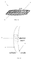
- FIG. 1A shows the non-axisymmetric diode 2 with a Child-Langmuir electron beam 8 with an elliptic cross-section having an anode 4 and cathode 6.
- FIG. 1B is a vertical cross-sectional view of the non-axisymmetric diode 2 and
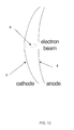
- FIG. 1C is a horizontal cross-sectional view of the non-axisymmetric diode 2 showing an electron beam 8 and the cathode 6 and anode 4 electrodes.
- the electron beam 8 has an elliptic cross section and the characteristics of Child-Langmuir flow.
- the particles are emitted from the cathode 6, and accelerated by the electric field between the cathode 6 and anode 4.
- the roles of cathode and anode are reversed.
- this forms an elliptic Cauchy problem, for which standard analytic and numerical solution methods fail due to the exponential growth of errors which is characteristic of all elliptic Cauchy problems.
- the present technique builds on the 2-dimensional technique of Radley in order to formulate a method of solution for the full 3D problem of determining the electrostatic potential outside a Child-Langmuir charged-particle beam of elliptic cross-section.
- the Angular Mathieu Functions ⁇ ⁇ ( ⁇ ) are not periodic. Indeed, a periodic solution arises only for certain characteristic eigenwalues of the separation constant a .
- the set of solutions ce 2 n is orthogonal and complete over the space of functions with the desired symmetry and periodicity properties.
- a number of methods may be used to evaluate the characteristic values a 2 n and the corresponding Angular Mathieu Functions ce 2 n . These can be integrated by standard methods. In practice, only the first few terms of the infinite series need be retained in order to reduce fractional errors to below 10 -5 .
- the integral along the contour C can be transformed into definite integrals of complex-valued functions along the real line, and thus it, too, can be evaluated using standard methods.
- the 3-dimensional charged-particle optics tool Omni-Trak has been used to simulate the emission and transport of charge particles in the geometry of FIGs. 3 and 4 .
- the resulting particle trajectories, shown in FIG. 5 are indeed parallel, as predicted by the theory.
- the results of the Omni-Trak simulation also provide a validation of the analytical method presented above.
- additional electrodes intermediate in potential between the cathode and anode, may be added in order to aid the enforcement of the Child-Langmuir flow condition.
- the above prescription allows for their design.
- neither the cathode electrode nor the intermediate electrodes need be extended arbitrarily close to the beam edge in order to enforce the Child-Langmuir flow condition.
- the portion of these electrodes nearest the beam may be excised without substantially affecting the beam solution.
- the analytically-prescribed electrodes correspond to the surfaces of conductors separated by vacuum and/or other insulating materials and (in some region distant from the beam) deviating from the analytically-prescribed profiles. Nevertheless, as the influence of distant portions of the electrodes diminish exponentially with distance from the beam edge, these deviations will have a negligible effect on the beam profile, provided that they occur at a sufficient distance from the beam edge.
- FIG. 5 depicts an Omni-Trak simulation in which the finiteness of the electrodes is evident without affecting the parallel-flow of the charged particle beam.
- FIG. 5 illustrates the charge collection surface 10, charge emitting surface 14, parallel particle trajectories 12, and analytically designed electrodes 16.
- the analytic method of electrode design detailed herein specifies the precise geometry of the charge-emitting 14 and charge-collecting 10 surfaces as well as the precise geometry of external conductors 16.
- These external conductors may be held at any potential, however, generally, two external conductors are used - one held at the emitter potential and the other at the collector potential.
- a charged-particle system designed conformally to this geometry will generate a high-quality, laminar, parallel-flow, Child-Langmuir beam of elliptic cross-section as shown in FIG 5 .
- FIG. 6 shows the iron pole pieces 18 and magnets 19 used to form the periodic magnetic field.
- the iron pole pieces are optional and may be omitted in other embodiments.
- the period of the magnetic field is defined by the line 20.
- the field distribution is illustrated FIG. 7 . Note FIG. 7 illustrates the field lines form by the iron pole pieces 18 and magnets 19 of FIG. 6 .
- ⁇ ( s ) is the angle of rotation of the ellipse with respect to the laboratory frame;
- the functions a ( s ), b ( s ), ⁇ x ( s ), ⁇ y ( s ), ⁇ x ( s ), ⁇ y ( s ) and ⁇ ( s ) are to be determined self-consistently [see Eqs. (2.11)-(2.15)].
- B ext x B 0 ⁇ k 0 ⁇ x k 0 ⁇ sinh k 0 ⁇ x ⁇ x ⁇ cosh k 0 ⁇ y ⁇ y ⁇ cos k 0 ⁇ s ⁇ e ⁇ x + k 0 ⁇ y k 0 ⁇ cosh k 0 ⁇ x ⁇ x ⁇ sinh k 0 ⁇ y ⁇ y ⁇ cos k 0 ⁇ s ⁇ e ⁇ y - cosh k 0 ⁇ x ⁇ x ⁇ cosh k 0 ⁇ y ⁇ y ⁇ sin k 0 ⁇ s ⁇ ⁇ e ⁇ z , and further expand it to the lowest order in the transverse dimension to obtain B ext x ⁇ B 0 ⁇
- the 3D magnetic field is specified by the three parameters B 0 , S and k 0 x / k 0 y .
- Equations (2.11)-(2.15) have the time reversal symmetry under the transformations (s, a,b,a',b', ⁇ x , ⁇ y , ⁇ ) ⁇ ( -s,a,b,-a',-b',- ⁇ x , ⁇ y , ⁇ ). This implies that the dynamical system described by Eqs. (2.11)-(2.15) has the hyper symmetry plane ( a',b', ⁇ x , ⁇ y ).
- a numerical module was developed to solve the generalized envelope equations (2.11)-(2.15). There are, in total, seven functions a ( s ) , b ( s ) , a' ( s ) , b' ( s ) , ⁇ x ( s ), ⁇ x ( s ) and ⁇ ( s ) to be solved.
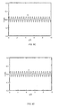
- FIGs. 9A demonstrates the envelopes associated with the functions a ( s ) and b ( s ).
- FIG. 9B is graphical representation of rotating angle ⁇ ( s ).
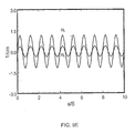
- FIG. 9E is a graph demonstrating velocities ⁇ x ( s ) and ⁇ y ( s ) versus the axial distance s for a flat, ellipse-shaped, uniform-density charged-particle beam in a 3D non-axisymmetric magnetic field.
- the matching from the charged-particle diode to the focusing channel might not be perfect in experiments. If a mismatch is unstable, it might ruin the beam. However, investigations of small-mismatch beams show that the envelopes are stable against small mismatch.
- FIGs. 10A demonstrates the envelopes associated with the functions a ( s ) and b ( s ).
- FIG. 10B is graphical representation of rotating angle ⁇ ( s ).
- FIG. 10E is a graph demonstrating velocities ⁇ x ( s ) and ⁇ y ( s ) versus the axial distance s for a flat, ellipse-shaped, uniform-density charged-particle beam in a 3D non-axisymmetric magnetic field.
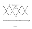
- FIG. 12 shows the envelopes for pulsating elliptic beam equilibrium in the periodic quadrupole magnetic field, as described previously.
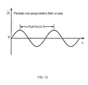
- FIG. 13 shows an example of the magnetic focusing parameter ⁇ z s ⁇ q ⁇ B z s 2 ⁇ ⁇ b ⁇ ⁇ b ⁇ m ⁇ c 2 associated with the non-axisymmetric periodic permanent magnetic field (presented for a beam of charged particles with charge q , rest mass m, and axial momentum ⁇ b ⁇ b mc.
- FIG. 14 shows the envelopes for a flat, elliptic beam equilibrium state in the non-axisymmetric periodic permanent magnetic field.
- the angle of the ellipse exhibits slight oscillations. However, these oscillations can be corrected by utilizing higher longitudinal harmonics of the magnetic field profile.
- the matching procedure discussed herein illustrates a high quality interface between a non-axisymmetric diode and a non-axisymmetric magnetic focusing channel for charged-particle beam.
- This beam system will find application in vacuum electron devices and particle accelerators where high brightness, low emittance, low temperature beams are desired.
Landscapes
- Engineering & Computer Science (AREA)
- Physics & Mathematics (AREA)
- Chemical & Material Sciences (AREA)
- Combustion & Propulsion (AREA)
- Spectroscopy & Molecular Physics (AREA)
- General Engineering & Computer Science (AREA)
- High Energy & Nuclear Physics (AREA)
- Analytical Chemistry (AREA)
- Particle Accelerators (AREA)
- Electron Beam Exposure (AREA)
Abstract
Description
- The invention relates to the field of charged-particle systems, and in particular to a non-axisymmmetric charged-particle system.
- The generation, acceleration and transport of a high-brightness, space-charge-dominated, charged-particle (electron or ion) beam are the most challenging aspects in the design and operation of vacuum electron devices and particle accelerators. A beam is said to be space-charge-dominated if its self-electric and self-magnetic field energy is greater than its thermal energy. Because the beam brightness is proportional to the beam current and inversely proportional to the product of the beam cross-sectional area and the beam temperature, generating and maintaining a beam at a low temperature is most critical in the design of a high-brightness beam. If a beam is designed not to reside in an equilibrium state, a sizable exchange occurs between the field and mean-flow energy and thermal energy in the beam. When the beam is space-charge-dominated, the energy exchange results in an increase in the beam temperature (or degradation in the beam brightness) as it propagates.
- If brightness degradation is not well contained, it can cause beam interception by radio-frequency (RF) structures in vacuum electron devices and particle accelerators, preventing them from operation, especially from high-duty operation. It can also make the beam from the accelerator unusable because of the difficulty of focusing the beam to a small spot size, as often required in accelerator applications.
- The design of high-brightness, space-charge-dominated, charged-particle beams relies on equilibrium beam theories and computer modeling. Equilibrium beam theories provide the guideline and set certain design goals, whereas computer modeling provides detailed implementation in the design.
- While some equilibrium states are known to exist, matching them between the continuous beam generation section and the continuous beam transport section has been a difficult task for beam designers and users, because none of the known equilibrium states for continuous beam generation can be perfectly matched into any of the known equilibrium states for continuous beam transport.
- For example, the equilibrium state from the Pierce diode in round two dimensional (2D) geometry cannot be matched into a periodic quadrupole magnetic field to create a Kapachinskij-Vladimirskij (KV) beam equilibrium. A rectangular beam made by cutting off the ends of the equilibrium state from the Pierce diode in infinite, 2D slab geometry ruins the equilibrium state.
- However, imperfection of beam matching in the beam system design yields the growth of beam temperature and the degradation of beam brightness as the beam propagates in an actual device.
- According to one aspect of the invention, there is provided a charged-particle beam system. The charged-particle beam system includes a non-axisymmetric diode which forms a non-axisymmetric beam having an elliptic cross-section. A focusing channel utilizes a magnetic field for focusing and transporting a non-axisymmetric beam,.
- According to another aspect of the invention, there is provided a non-axisymmetric diode. The non-axisymmetric diode comprises at least one electrical terminal for emitting charged-particles and at least one electrical terminal for establishing an electric field and accelerating charged-particles to form a charged-particle beam. These terminals are arranged such that the charged-particle beam possesses an elliptic cross-section.
- According to another aspect of the invention, there is provided a method of forming a non-axisymmetric diode comprising forming at least one electrical terminal for emitting charged-particles, forming at least one electrical terminal for establishing an electric field and accelerating charged-particles to form a charged-particle beam, and arranging said terminals such that the charged-particle beam possesses an elliptic cross-section.
- According to another aspect of the invention, there is provided a charged-particle focusing and transport channel wherein a non-axisymmetric magnetic field is used to focus and transport a charged-particle beam of elliptic cross-section.
- According to another aspect of the invention, there is provided a method of designing a charged-particle focusing and transport channel wherein a non-axisymmetric magnetic field is used to focus and transport a charged-particle beam of elliptic cross-section.
- According to another aspect of the invention, there is provided a method of designing an interface for matching a charged-particle beam of elliptic-cross section between a non-axisymmetric diode and a non-axisymmetric magnetic focusing and transport channel.
- According to another aspect of the invention, there is provided a method of forming a charged-particle beam system. The method includes forming a non-axisymmetric diode that includes a non-axisymmetric beam having an elliptic cross-section. Also, the method includes forming a focusing channel that utilizes a magnetic field for focusing and transporting the elliptic cross-section beam.
-
-
FIGs. 1A-1C are schematic diagrams demonstrating a non-axisymmetric diode; -
FIG. 2 is a graph demonstrating the Integration Contour C for the potential Φ ; -
FIG. 3 is a graph demonstrating the cross-section of the Φ = 0 electrode at various positions along the beam axis; -
FIG. 4 is a graph demonstrating the cross-section of the Φ = V electrode at various positions along the beam axis.; -
FIG. 5 is a schematic diagram demonstrating the electrode geometry of a well-confined, parallel beam of elliptic cross section; -
FIG. 6 is a schematic diagram of a non-axisymmetric periodic magnetic field; -
FIG. 7 is a schematic diagram of the field distribution of a non-axisymmetric periodic magnetic field; -
FIG. 8 is a schematic diagram demonstrating the laboratory and rotating coordinate systems; -
FIGs. 9A-9E are graphs demonstrating matched solutions of the generalized envelope equations for a non-axisymmetric beam system with parameters corresponding to: k 0x = 3.22 cm -1, k 0y = 5.39 cm -1,
-
FIGS. 10A-10E are graphs demonstrating the envelopes and flow velocities for a non-axisymmetric beam system with the choice of system parameters corresponding to:k 0x = 3.22 cm -1, k 0y = 5.39 cm -1,
-
FIG. 11 is a graph demonstrating the focusing parameter for a periodic quadrupole magnetic field; -
FIG. 12 is a graph demonstrating the beam envelopes of a pulsating elliptic beam equilibrium state in the periodic quadrupole magnetic field shown inFIG. 11 ; -
FIG. 13 is a graph demonstrating the focusing parameter for a non-axisymmetric periodic permanent magnetic field; and -
FIG. 14 is a graph demonstrating the beam envelopes of an elliptic beam equilibrium state in the non-axisymmetric periodic permanent magnetic field shown inFIG. 13 . - The invention comprises a non-axisymmetric charged-particle beam system having a novel design and method of design for non-axisymmetric charged-particle diodes.
- A
non-axisymmetric diode 2 is shown schematically inFIGs. 1A-1C .FIG. 1A shows thenon-axisymmetric diode 2 with a Child-Langmuir electron beam 8 with an elliptic cross-section having ananode 4 andcathode 6.FIG. 1B is a vertical cross-sectional view of thenon-axisymmetric diode 2 andFIG. 1C is a horizontal cross-sectional view of thenon-axisymmetric diode 2 showing anelectron beam 8 and thecathode 6 andanode 4 electrodes. - The
electron beam 8 has an elliptic cross section and the characteristics of Child-Langmuir flow. The particles are emitted from thecathode 6, and accelerated by the electric field between thecathode 6 andanode 4. For an ion beam, the roles of cathode and anode are reversed. - To describe the method of designing an non-axisymmetric diode with an elliptic cross-section, one can introduce the elliptic coordinate system (ξ,η,z;f), defined in terms of the usual Cartesian coordinates by

where ξ ∈ [0,∞) is a radial coordinate, η ∈ [0,2;π) is an angular coordinate, and ƒ is a constant scaling parameter. A charged-particle beam flowing in the ê z direction and taking the Child-Langmuir profile of parallel flow with uniform transverse density will possess an internal electrostatic potential of
where one can have defined Φ(z = 0) = 0 along a planar charge-emitting surface and Φ(z = d) = V along a planar charge-accepting surface. - If both planes have transverse boundaries of elliptic shape, specified by the surface ξ = ξ0 = constant , then a solution exists for a parallel flow, uniform transverse density, Child-Langmuir charged-particle beam of elliptic cross-section, flowing between the planes at z = 0 and z = d . Due to the mutual space-charge repulsion of the particles constituting the beam, this Child-Langmuir profile must be supported by the imposition of an external electric field through the construction of appropriately shaped electrodes. The design of said electrodes requires knowledge of the electrostatic potential function external to the beam which satisfies appropriate boundary conditions on the beam edge:

- As the potential and its normal derivative are specified independently on the surface ξ = ξ0, this forms an elliptic Cauchy problem, for which standard analytic and numerical solution methods fail due to the exponential growth of errors which is characteristic of all elliptic Cauchy problems. The present technique builds on the 2-dimensional technique of Radley in order to formulate a method of solution for the full 3D problem of determining the electrostatic potential outside a Child-Langmuir charged-particle beam of elliptic cross-section.
- In the region external to the beam, the potential satisfies Laplace's equation, which is written in elliptic coordinates as

where one can follow the usual technique of separation of variables, writing F(ξ,η,z)=Z(z)T(ξ,η) and introducing the separation constant k 2. The separated equations can now be written as

where one can have performed another separation on the transverse equation, writing T(ξ,η) = R(ξ)Θ(η) and introducing the separation constant a. This last equation thus yields

- Solutions to the separated transverse equations are known as the Radial Mathieu Functions R(ξ) and Angular Mathieu Functions Θ(η), respectively, while the solutions to the separated longitudinal equation are easily expressed in terms of exponentials Z(z) ∝ e ±kz .
- The solution for the potential is now represented as a superposition of separable solutions which, jointly, satisfy the boundary conditions on (Φ. One can write

where the amplitude functions A(k) and B(a) are introduced and the integration contours are as yet unspecified. In order to satisfy the boundary condition on Φ along the beam edge, using the analytic continuation of the Gamma function, one can write
where the integration contour C is taken around the branch cut as shown inFIG. 2 . - One can then write the boundary condition as

The boundary condition is satisfied by choosing C as the integration contour for the representation of Φ and making the correspondences
and
- The physical system requires a solution periodic in η and symmetric about η = 0 and η = π/2. In general, the Angular Mathieu Functions Θα(η) are not periodic. Indeed, a periodic solution arises only for certain characteristic eigenwalues of the separation constant a. There are 4 infinite and discrete sets of eigenvalues denoted by α 2n , α 2n+1, b 2n , b 2n+1 for n ∈ {0, 1, 2,...} which differ in their symmetry properties. Only the set a 2n and the corresponding cosine-elliptic solutions denoted by Θ(η)=ce 2n (η;k) possess the appropriate symmetries, and the integral over a becomes a sum of the
form 
- Moreover, the set of solutions ce 2n is orthogonal and complete over the space of functions with the desired symmetry and periodicity properties. Thus one can expand unity as

The boundary condition on Φ is then satisfied by choosing
and
The condition that the normal derivative of the potential vanishes along the beam surface implies
which, along with the boundary value of R α2n and the eigenvalue a 2n , fully specify the second-order Radial Mathieu Equation. It can then be integrated by standard methods in order to determine the radial solutions. - Thus, one may rewrite the expansion for Φ as

A number of methods may be used to evaluate the characteristic values a 2n and the corresponding Angular Mathieu Functions ce 2n . These can be integrated by standard methods. In practice, only the first few terms of the infinite series need be retained in order to reduce fractional errors to below 10-5. The integral along the contour C can be transformed into definite integrals of complex-valued functions along the real line, and thus it, too, can be evaluated using standard methods. - Once the potential profile is known, one can employ a root-finding technique in order to determine surfaces along which one may place constant-potential electrodes. A numerical module has been developed which determines these electrode shapes based on the theory described and solution methods described above. Sample electrode designs are shown in
FIGs. 3 and 4 for the case of a 10:1 elliptical beam of semi-major radius 6mm and semi-minor radius 0.6mm. These electrodes serve to enforce the analytically-derived potential profile along the beam edge, which in turn serves to confine the beam and maintain it in the Child-Langmuir form. - The 3-dimensional charged-particle optics tool Omni-Trak has been used to simulate the emission and transport of charge particles in the geometry of
FIGs. 3 and 4 . The resulting particle trajectories, shown inFIG. 5 , are indeed parallel, as predicted by the theory. The results of the Omni-Trak simulation also provide a validation of the analytical method presented above. - One will often wish to extract this beam and inject it into another device by excising a portion of the charge-collecting plate. Doing so will modify the boundary conditions of the problem such that the above solution can no longer be considered exact, however, the errors introduced by relatively small excisions will be negligible, and the appropriate electrode shapes will be substantially unchanged from those produced by the method outlined above.
- It should also be noted that additional electrodes, intermediate in potential between the cathode and anode, may be added in order to aid the enforcement of the Child-Langmuir flow condition. The above prescription allows for their design. As with the charge-collecting plate, neither the cathode electrode nor the intermediate electrodes need be extended arbitrarily close to the beam edge in order to enforce the Child-Langmuir flow condition. The portion of these electrodes nearest the beam may be excised without substantially affecting the beam solution.
- Along similar lines, in a physical device, one cannot extend the electrodes infinitely far in the transverse directions. The analytically-prescribed electrodes correspond to the surfaces of conductors separated by vacuum and/or other insulating materials and (in some region distant from the beam) deviating from the analytically-prescribed profiles. Nevertheless, as the influence of distant portions of the electrodes diminish exponentially with distance from the beam edge, these deviations will have a negligible effect on the beam profile, provided that they occur at a sufficient distance from the beam edge.
-
FIG. 5 depicts an Omni-Trak simulation in which the finiteness of the electrodes is evident without affecting the parallel-flow of the charged particle beam. NoteFIG. 5 illustrates thecharge collection surface 10,charge emitting surface 14,parallel particle trajectories 12, and analytically designedelectrodes 16. By equating the electrode geometry with equipotential surfaces, the analytic method of electrode design detailed herein specifies the precise geometry of the charge-emitting 14 and charge-collecting 10 surfaces as well as the precise geometry ofexternal conductors 16. These external conductors may be held at any potential, however, generally, two external conductors are used - one held at the emitter potential and the other at the collector potential. A charged-particle system designed conformally to this geometry will generate a high-quality, laminar, parallel-flow, Child-Langmuir beam of elliptic cross-section as shown inFIG 5 . - As an illustrated example, a non-axisymmetric periodic magnetic field for focusing and transporting a non-axisymmetric beam is shown
FIG. 6. FIG. 6 shows theiron pole pieces 18 andmagnets 19 used to form the periodic magnetic field. The iron pole pieces are optional and may be omitted in other embodiments. The period of the magnetic field is defined by theline 20. The field distribution is illustratedFIG. 7 . NoteFIG. 7 illustrates the field lines form by theiron pole pieces 18 andmagnets 19 ofFIG. 6 . - For a high-brightness, space-charge-dominated beam, kinetic (emittance) effects are negligibly small, and the beam can be adequately described by cold-fluid equations. In the paraxial approximation, the steady-state cold-fluid equations for time-stationary flow (∂/∂t = 0) in cgs units are:



where s = z, q and m are the particle charge and rest mass, respectively,
is the relativistic mass factor, use has been made of β z ≅ βb = const, and the self-electric field E s and self-magnetic field B s are determined from the scalar potential φ s and vector potential
- One seeks solutions to Eqs. (2.1)-(2.3) of the form


In Eqs. (2.4) and (2.5),
FIG. 8 ; θ(s) is the angle of rotation of the ellipse with respect to the laboratory frame; Θ(x) = 1 if x > 0 and Θ(x) = 0 if x < 0; and the functions a(s), b(s), µ x (s), µ y (s), αx (s), αy (s) and θ(s) are to be determined self-consistently [see Eqs. (2.11)-(2.15)]. - For the self-electric and self-magnetic fields, Eqs. (2.2) and (2.4) are solved to obtain the scalar and vector potentials

- For a 3D non-axisymmetric periodic magnetic field with an axial periodicity length of S, one can describe it as the fundamental mode,

and further expand it to the lowest order in the transverse dimension to obtain
In Eqs. (2.7) and (2.8),

The 3D magnetic field is specified by the three parameters B 0 , S and k 0x / k 0y . - Using the expressions in Eqs. (2.5), (2.6) and (2.8), it can be shown that both the equilibrium continuity and force equations (2.1) and (2.3) are satisfied if the dynamical variables a(s), b(s), µ x (s)≡a -1 da/ds, µy (s)≡b -1 db/ds, αx (s), αy (s) and θ(s) obey the generalized beam envelope equations:


where
- Equations (2.11)-(2.15) have the time reversal symmetry under the transformations (s,a,b,a',b',αx,αy,θ) → (-s,a,b,-a',-b',-αx,αy,θ). This implies that the dynamical system described by Eqs. (2.11)-(2.15) has the hyper symmetry plane (a',b',αx,αy ).
- A numerical module was developed to solve the generalized envelope equations (2.11)-(2.15). There are, in total, seven functions a(s), b(s), a'(s), b'(s), αx (s), αx (s) and θ(s) to be solved. The time inverse symmetry of the dynamical system requires the quantities (a',b',αx,αy ) vanish at s = 0 for matched solutions, therefore, only the three initial values a(0), b(0) and θ(0) corresponding to a matched solution need to be determined by using Newton's method. The matched solutions of the generalized envelope equations are shown in
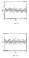
FIGs. 9A-9E for a non-axisymmetric beam system with the choice of system parameters corresponding to: k 0x = 3.22 cm -1, k 0y = 5.39 cm -1, √kz = 0.805 cm -1, K = 1.53×10⁻² and axial periodicity length S = 0.956 cm. - In particular,
FIGs. 9A demonstrates the envelopes associated with the functions a(s) and b(s).FIG. 9B is graphical representation of rotating angle θ(s).FIG. 9C is a graph illustrating velocity
FIG. 9D is a graph demonstrating velocity
FIG. 9E is a graph demonstrating velocities α x (s) and αy (s) versus the axial distance s for a flat, ellipse-shaped, uniform-density charged-particle beam in a 3D non-axisymmetric magnetic field. - The matching from the charged-particle diode to the focusing channel might not be perfect in experiments. If a mismatch is unstable, it might ruin the beam. However, investigations of small-mismatch beams show that the envelopes are stable against small mismatch.
- For example, the envelopes and flow velocities are plotted in
FIGs. 10A-10E for a non-axisymmetric beam system with the choice of system parameters corresponding to: k 0x = 3.22 cm -1, k 0y = 5.39 cm -1, √Kz = 0.805 cm -1, K = 1.53×10⁻² and axial periodicity length S = 0.956 cm with an initial 5% mismatch of θ, i.e. θ(s = 0)=θ matched (s = 0)×(1.05). - In particular,
FIGs. 10A demonstrates the envelopes associated with the functions a(s) and b(s).FIG. 10B is graphical representation of rotating angle θ(s).FIG. 10C is a graph illustrating velocity
FIG. 10D is a graph demonstrating velocity
FIG. 10E is a graph demonstrating velocities αx (s) and αy (s) versus the axial distance s for a flat, ellipse-shaped, uniform-density charged-particle beam in a 3D non-axisymmetric magnetic field. - By the technique described herein, one can design a non-axisymmetric magnetic focusing channel which preserves a uniform-density, laminar charged-particle beam of elliptic cross-section.
- One can illustrate how to match an elliptic charged-particle beam from the non-axisymmetric diode, described herein, into a periodic quadrupole magnetic field. In the paraxial approximation, the periodic quadrupole magnetic field is described by

The concept of matching is illustrated inFIGs. 11 and12 . -
FIG. 11 shows an example of the magnetic focusing parameter
associated with the periodic quadrupole magnetic field for a beam of charged particles with charge q, rest mass m, and axial momentum γbβbmc. -
FIG. 12 shows the envelopes for pulsating elliptic beam equilibrium in the periodic quadrupole magnetic field, as described previously. - The matching of the equilibrium state from the diode to the equilibrium state for the periodic quadrupole magnetic field at s = 0 is feasible, because the transverse density profile and flow velocity of the two equilibrium states are identical at s = 0 . In particular, the transverse particle density is uniform within the beam ellipse and the transverse flow velocity vanishes at s = 0 .
- Also, one can illustrate how to match an elliptic charged-particle beam from the non-axisymmetric diode, as described herein, into a non-axisymmetric periodic permanent magnetic field. In the paraxial approximation, the non-axisymmetric permanent magnetic field is described by Eq. (2.8). The concept of matching is illustrated in
FIGs. 13 and14 . -
FIG. 13 shows an example of the magnetic focusing parameter
associated with the non-axisymmetric periodic permanent magnetic field (presented for a beam of charged particles with charge q, rest mass m, and axial momentum γbβbmc. -
FIG. 14 shows the envelopes for a flat, elliptic beam equilibrium state in the non-axisymmetric periodic permanent magnetic field. The angle of the ellipse exhibits slight oscillations. However, these oscillations can be corrected by utilizing higher longitudinal harmonics of the magnetic field profile. - The matching of the equilibrium state from the diode to the equilibrium state for the non-axisymmetric periodic permanent magnetic field at s = 0 is feasible, because the transverse density profile and flow velocity of the two equilibrium states are identical. In particular, the transverse particle density is uniform within the beam ellipse and the transverse flow velocity vanishes at s = 0 .
- The matching procedure discussed herein illustrates a high quality interface between a non-axisymmetric diode and a non-axisymmetric magnetic focusing channel for charged-particle beam.
- This beam system will find application in vacuum electron devices and particle accelerators where high brightness, low emittance, low temperature beams are desired.
- Although the present invention has been shown and described with respect to several preferred embodiments thereof, various changes, omissions and additions to the form and detail thereof, may be made therein, without departing from the spirit and scope of the invention.
Claims (32)
- A charged-particle beam system, characterized in that said charged-particle beam system comprises;
a non-axisymmetric diode that forms a non-axisymmetric beam having an elliptic cross-section; and
a focusing channel that utilizes a magnetic field for focusing and transporting said elliptic cross-section beam. - The charged-particle beam system of claim of 1, characterized in that said charged-particle beam possesses a uniform transverse density profile.
- The charged-particle beam system of claim of 1, characterized in that said charged-particle beam possesses a laminar flow profile.
- The charged-particle beam system of claim of 1, characterized in that said charged-particle beam possesses a parallel longitudinal flow profile.
- The charged-particle beam system of claim 1, characterized in that said focusing channel comprises a non-axisymmetric magnetic field for focusing and transporting said charged-particle beam.
- The charged-particle beam system of claim 5, characterized in that said non-axisymmetric magnetic field includes a non-axisymmetric periodic magnetic field.
- The charged-particle beam system of claim 5, characterized in that said non-axisymmetric magnetic field includes a non-axisymmetric permanent magnetic field.
- The charged-particle beam system of claim 5, characterized in that said non-axisymmetric magnetic field includes a non-axisymmetric periodic permanent magnetic field.
- The charged-particle beam system of claim of 5, characterized in that said non-axisymmetric magnetic field includes at least one quadrupole magnetic field.
- The charged-particle beam system of claim of 5, characterized in that said non-axisymmetric magnetic field includes a periodic quadrupole magnetic field.
- The charged-particle beam system of claim 2, characterized in that said focusing channel comprises a non-axisymmetric magnetic field for focusing and transporting said charged-particle beam.
- The charged-particle beam system of claim 11, characterized in that said non-axisymmetric magnetic field includes a non-axisymmetric periodic magnetic field.
- The charged-particle beam system of claim 11, characterized in that said non-axisymmetric magnetic field includes a non-axisymmetric permanent magnetic field.
- The charged-particle beam system of claim 11, characterized in that said non-axisymmetric magnetic field includes a non-axisymmetric periodic permanent magnetic field.
- The charged-particle beam system of claim of 11, characterized in that said non-axisymmetric magnetic field includes at least one quadrupole magnetic field.
- The charged-particle beam system of claim of 11, characterized in that said non-axisymmetric magnetic field includes a periodic quadrupole magnetic field.
- A method of forming a charged-particle beam system comprising, characterized in that said method comprises the steps of;
forming a non-axisymmetric diode that includes a non-axisymmetric beam having an elliptic cross-section; and
forming a focusing channel that utilizes a magnetic field for focusing and transporting said elliptic cross-section beam. - The method of claim 17, characterized in that said charged-particle beam possesses a uniform transverse density profile.
- The method of claim 17, characterized in that said charged-particle beam possesses a laminar flow profile.
- The method of claim 17, characterized in that said charged-particle beam possesses a parallel longitudinal flow profile.
- The method of claim 17, characterized in that said focusing channel comprises a non-axisymmetric magnetic field for focusing and transporting said charged-particle beam.
- The method of claim 21, characterized in that said non-axisymmetric magnetic field includes a non-axisymmetric periodic magnetic field.
- The method of claim 21, characterized in that said non-axisymmetric magnetic field includes a non-axisymmetric permanent magnetic field.
- The method of claim 21, characterized in that said non-axisymmetric magnetic field includes a non-axisymmetric periodic permanent magnetic field.
- The method of claim 21, characterized in that said non-axisymmetric magnetic field includes at least one quadrupole magnetic field.
- The method of claim 21, characterized in that said non-axisymmetric magnetic field includes a periodic quadrupole magnetic field.
- The method of claim 18, characterized in that said focusing channel comprises a non-axisymmetric magnetic field for focusing and transporting said charged-particle beam.
- The charged-particle beam system of claim 27, characterized in that said non-axisymmetric magnetic field includes a non-axisymmetric periodic magnetic field.
- The charged-particle beam system of claim 27, characterized in that said non-axisymmetric magnetic field includes a non-axisymmetric permanent magnetic field.
- The charged-particle beam system of claim 27, characterized in that said non-axisymmetric magnetic field includes a non-axisymmetric periodic permanent magnetic field.
- The charged-particle beam system of claim of 27, characterized in that said non-axisymmetric magnetic field includes at least one quadrupole magnetic field.
- The charged-particle beam system of claim of 27, characterized in that said non-axisymmetric magnetic field includes a periodic quadrupole magnetic field.
Applications Claiming Priority (2)
| Application Number | Priority Date | Filing Date | Title |
|---|---|---|---|
| US57713204P | 2004-06-04 | 2004-06-04 | |
| EP05758447A EP1766652A2 (en) | 2004-06-04 | 2005-06-06 | Non-axisymmmetric charged-particle beam system |
Related Parent Applications (1)
| Application Number | Title | Priority Date | Filing Date |
|---|---|---|---|
| EP05758447A Division EP1766652A2 (en) | 2004-06-04 | 2005-06-06 | Non-axisymmmetric charged-particle beam system |
Publications (2)
| Publication Number | Publication Date |
|---|---|
| EP1968094A2 true EP1968094A2 (en) | 2008-09-10 |
| EP1968094A3 EP1968094A3 (en) | 2010-01-06 |
Family
ID=35262203
Family Applications (2)
| Application Number | Title | Priority Date | Filing Date |
|---|---|---|---|
| EP05758447A Withdrawn EP1766652A2 (en) | 2004-06-04 | 2005-06-06 | Non-axisymmmetric charged-particle beam system |
| EP08157418A Withdrawn EP1968094A3 (en) | 2004-06-04 | 2005-06-06 | Non-axisymmetric charged-particle beam system |
Family Applications Before (1)
| Application Number | Title | Priority Date | Filing Date |
|---|---|---|---|
| EP05758447A Withdrawn EP1766652A2 (en) | 2004-06-04 | 2005-06-06 | Non-axisymmmetric charged-particle beam system |
Country Status (6)
| Country | Link |
|---|---|
| US (2) | US7381967B2 (en) |
| EP (2) | EP1766652A2 (en) |
| JP (1) | JP2008502110A (en) |
| KR (1) | KR20070034569A (en) |
| CN (1) | CN1998059A (en) |
| WO (1) | WO2005119732A2 (en) |
Families Citing this family (5)
| Publication number | Priority date | Publication date | Assignee | Title |
|---|---|---|---|---|
| JP4851185B2 (en) | 2003-05-16 | 2012-01-11 | ジェレックスインターナショナル株式会社 | Allergy symptom suppressant and air filtration filter |
| US7381967B2 (en) * | 2004-06-04 | 2008-06-03 | Massachusetts Institute Of Technology | Non-axisymmetric charged-particle beam system |
| US20110121194A1 (en) * | 2006-10-16 | 2011-05-26 | Bhatt Ronak J | Controlled transport system for an elliptic charged-particle beam |
| WO2008061173A2 (en) * | 2006-11-15 | 2008-05-22 | Massachusetts Institute Of Technology | Generation, acceleration, focusing and collection of a high-brightness, space-charge-dominated circular charged-particle beam |
| US8314404B2 (en) * | 2009-09-18 | 2012-11-20 | Fei Company | Distributed ion source acceleration column |
Family Cites Families (4)
| Publication number | Priority date | Publication date | Assignee | Title |
|---|---|---|---|---|
| GB574512A (en) | 1940-03-05 | 1946-01-09 | Leonard Francis Broadway | Improvements in or relating to electron discharge devices |
| EP0739492B1 (en) | 1993-01-11 | 2000-06-07 | Real Time Electronics Corporation | High frequency scan converter |
| US6326861B1 (en) * | 1999-07-16 | 2001-12-04 | Feltech Corporation | Method for generating a train of fast electrical pulses and application to the acceleration of particles |
| US7381967B2 (en) * | 2004-06-04 | 2008-06-03 | Massachusetts Institute Of Technology | Non-axisymmetric charged-particle beam system |
-
2005
- 2005-06-06 US US11/145,804 patent/US7381967B2/en not_active Expired - Fee Related
- 2005-06-06 WO PCT/US2005/019794 patent/WO2005119732A2/en not_active Ceased
- 2005-06-06 CN CNA2005800229310A patent/CN1998059A/en active Pending
- 2005-06-06 KR KR1020077000133A patent/KR20070034569A/en not_active Ceased
- 2005-06-06 JP JP2007515673A patent/JP2008502110A/en not_active Withdrawn
- 2005-06-06 EP EP05758447A patent/EP1766652A2/en not_active Withdrawn
- 2005-06-06 EP EP08157418A patent/EP1968094A3/en not_active Withdrawn
-
2008
- 2008-01-03 US US11/968,833 patent/US7612346B2/en not_active Expired - Fee Related
Also Published As
| Publication number | Publication date |
|---|---|
| CN1998059A (en) | 2007-07-11 |
| US20060017002A1 (en) | 2006-01-26 |
| WO2005119732A2 (en) | 2005-12-15 |
| EP1766652A2 (en) | 2007-03-28 |
| KR20070034569A (en) | 2007-03-28 |
| US20080191144A1 (en) | 2008-08-14 |
| WO2005119732A3 (en) | 2006-02-09 |
| US7381967B2 (en) | 2008-06-03 |
| US7612346B2 (en) | 2009-11-03 |
| EP1968094A3 (en) | 2010-01-06 |
| JP2008502110A (en) | 2008-01-24 |
Similar Documents
| Publication | Publication Date | Title |
|---|---|---|
| Joshi et al. | Plasma wakefield acceleration experiments at FACET II | |
| Wang et al. | Electron beam transport analysis of W-band sheet beam klystron | |
| US7612346B2 (en) | Non-axisymmetric charged-particle beam system | |
| Staples | RFQ's-An Introduction | |
| Basten et al. | Magnetic quadrupole formation of elliptical sheet electron beams for high-power microwave devices | |
| Mamontov et al. | Numerical Analysis of Runaway Electron Beam Focusing with a Homogeneous Longitudinal Magnetic Field | |
| Lindqvist et al. | Sensitivity of the negative ion beam extraction to initial plasma parameters by 3D particle modelling | |
| Panda et al. | Pole-piece with stepped hole for stable sheet electron beam transport under uniform magnetic field | |
| US7663327B2 (en) | Non-axisymmetric periodic permanent magnet focusing system | |
| US20110121194A1 (en) | Controlled transport system for an elliptic charged-particle beam | |
| Naab et al. | Ion beam transport simulations for the 1.7 MV tandem accelerator at the Michigan ion beam laboratory | |
| Harris et al. | Transport of electron beams with initial transverse-longitudinal correlation | |
| Zhang et al. | Two-dimensional numerical simulation of the splitting and uniting of current-carrying zones in a dielectric barrier discharge | |
| Weinberg et al. | Beam-line optimization based on realistic electron-optics 3D field-maps implementation provides high-quality e-beam via a dogleg section | |
| Harris et al. | Solenoid transport of beams with current-dependent initial conditions | |
| Nichols et al. | Analysis of quadrupole focusing lattices for electron beam transport in traveling-wave tubes | |
| Hong et al. | Preliminary physical and electromagnetic design for the injector of the heavy ion superconducting linac | |
| Harris et al. | Generation and focusing of electron beams with initial transverse-longitudinal correlation | |
| Grigoreva et al. | Energy loss reduction of a charge moving through an anisotropic plasma-like medium | |
| Levchenko | Fields of an ultra-relativistic beam of charged particles between parallel plates. Exact 2D solutions by the method of images and applications to the HL-LHC | |
| Martinez et al. | Classical trajectory Monte Carlo simulation of plasma fueling using magnetic plasma expulsion | |
| Slayton et al. | Micron-Scale Electrostatic Charged-Particle Guides: Analysis and Simulation | |
| Todd et al. | Comparison of particle-in-cell simulation with experiment for the transport system of the superconducting electron cyclotron resonance ion source VENUS | |
| Ikeda et al. | Simulation study of high-current 7Li3+ beam acceleration with laser ion source and RFQ linac using direct plasma injection | |
| Yang et al. | Theoretical study of magnetic lens with parallel beam matched |
Legal Events
| Date | Code | Title | Description |
|---|---|---|---|
| PUAI | Public reference made under article 153(3) epc to a published international application that has entered the european phase |
Free format text: ORIGINAL CODE: 0009012 |
|
| AC | Divisional application: reference to earlier application |
Ref document number: 1766652 Country of ref document: EP Kind code of ref document: P |
|
| AK | Designated contracting states |
Kind code of ref document: A2 Designated state(s): AT BE BG CH CY CZ DE DK EE ES FI FR GB GR HU IE IS IT LI LT LU MC NL PL PT RO SE SI SK TR |
|
| RIN1 | Information on inventor provided before grant (corrected) |
Inventor name: BHATT, RHONAK, J Inventor name: ZHOU, JING Inventor name: CHEN, CHIPING |
|
| RIN1 | Information on inventor provided before grant (corrected) |
Inventor name: CHEN, CHIPING Inventor name: ZHOU, JING Inventor name: BHATT, RHONAK, J |
|
| PUAL | Search report despatched |
Free format text: ORIGINAL CODE: 0009013 |
|
| AK | Designated contracting states |
Kind code of ref document: A3 Designated state(s): AT BE BG CH CY CZ DE DK EE ES FI FR GB GR HU IE IS IT LI LT LU MC NL PL PT RO SE SI SK TR |
|
| RIC1 | Information provided on ipc code assigned before grant |
Ipc: H01J 3/12 20060101AFI20091201BHEP Ipc: H01J 3/14 20060101ALI20091201BHEP |
|
| STAA | Information on the status of an ep patent application or granted ep patent |
Free format text: STATUS: THE APPLICATION IS DEEMED TO BE WITHDRAWN |
|
| 18D | Application deemed to be withdrawn |
Effective date: 20100105 |