EP1967699B1 - Gasturbinentriebwerk mit einer abschleifbaren Dichtung - Google Patents
Gasturbinentriebwerk mit einer abschleifbaren Dichtung Download PDFInfo
- Publication number
- EP1967699B1 EP1967699B1 EP08250742A EP08250742A EP1967699B1 EP 1967699 B1 EP1967699 B1 EP 1967699B1 EP 08250742 A EP08250742 A EP 08250742A EP 08250742 A EP08250742 A EP 08250742A EP 1967699 B1 EP1967699 B1 EP 1967699B1
- Authority
- EP
- European Patent Office
- Prior art keywords
- gas turbine
- airfoil
- turbine engine
- engine
- abradable
- Prior art date
- Legal status (The legal status is an assumption and is not a legal conclusion. Google has not performed a legal analysis and makes no representation as to the accuracy of the status listed.)
- Revoked
Links
Images

Classifications
-
- F—MECHANICAL ENGINEERING; LIGHTING; HEATING; WEAPONS; BLASTING
- F04—POSITIVE - DISPLACEMENT MACHINES FOR LIQUIDS; PUMPS FOR LIQUIDS OR ELASTIC FLUIDS
- F04D—NON-POSITIVE-DISPLACEMENT PUMPS
- F04D29/00—Details, component parts, or accessories
- F04D29/08—Sealings
- F04D29/16—Sealings between pressure and suction sides
- F04D29/161—Sealings between pressure and suction sides especially adapted for elastic fluid pumps
- F04D29/164—Sealings between pressure and suction sides especially adapted for elastic fluid pumps of an axial flow wheel
-
- F—MECHANICAL ENGINEERING; LIGHTING; HEATING; WEAPONS; BLASTING
- F01—MACHINES OR ENGINES IN GENERAL; ENGINE PLANTS IN GENERAL; STEAM ENGINES
- F01D—NON-POSITIVE DISPLACEMENT MACHINES OR ENGINES, e.g. STEAM TURBINES
- F01D11/00—Preventing or minimising internal leakage of working-fluid, e.g. between stages
- F01D11/001—Preventing or minimising internal leakage of working-fluid, e.g. between stages for sealing space between stator blade and rotor
-
- F—MECHANICAL ENGINEERING; LIGHTING; HEATING; WEAPONS; BLASTING
- F01—MACHINES OR ENGINES IN GENERAL; ENGINE PLANTS IN GENERAL; STEAM ENGINES
- F01D—NON-POSITIVE DISPLACEMENT MACHINES OR ENGINES, e.g. STEAM TURBINES
- F01D11/00—Preventing or minimising internal leakage of working-fluid, e.g. between stages
- F01D11/08—Preventing or minimising internal leakage of working-fluid, e.g. between stages for sealing space between rotor blade tips and stator
- F01D11/12—Preventing or minimising internal leakage of working-fluid, e.g. between stages for sealing space between rotor blade tips and stator using a rubstrip, e.g. erodible. deformable or resiliently-biased part
- F01D11/122—Preventing or minimising internal leakage of working-fluid, e.g. between stages for sealing space between rotor blade tips and stator using a rubstrip, e.g. erodible. deformable or resiliently-biased part with erodable or abradable material
-
- F—MECHANICAL ENGINEERING; LIGHTING; HEATING; WEAPONS; BLASTING
- F04—POSITIVE - DISPLACEMENT MACHINES FOR LIQUIDS; PUMPS FOR LIQUIDS OR ELASTIC FLUIDS
- F04D—NON-POSITIVE-DISPLACEMENT PUMPS
- F04D29/00—Details, component parts, or accessories
- F04D29/08—Sealings
- F04D29/083—Sealings especially adapted for elastic fluid pumps
-
- F—MECHANICAL ENGINEERING; LIGHTING; HEATING; WEAPONS; BLASTING
- F05—INDEXING SCHEMES RELATING TO ENGINES OR PUMPS IN VARIOUS SUBCLASSES OF CLASSES F01-F04
- F05B—INDEXING SCHEME RELATING TO WIND, SPRING, WEIGHT, INERTIA OR LIKE MOTORS, TO MACHINES OR ENGINES FOR LIQUIDS COVERED BY SUBCLASSES F03B, F03D AND F03G
- F05B2230/00—Manufacture
- F05B2230/90—Coating; Surface treatment
-
- F—MECHANICAL ENGINEERING; LIGHTING; HEATING; WEAPONS; BLASTING
- F05—INDEXING SCHEMES RELATING TO ENGINES OR PUMPS IN VARIOUS SUBCLASSES OF CLASSES F01-F04
- F05D—INDEXING SCHEME FOR ASPECTS RELATING TO NON-POSITIVE-DISPLACEMENT MACHINES OR ENGINES, GAS-TURBINES OR JET-PROPULSION PLANTS
- F05D2230/00—Manufacture
- F05D2230/90—Coating; Surface treatment
Definitions
- This invention generally relates to a gas turbine engine, and more particularly to an abradable component for a gas turbine engine.
- Gas turbine engines typically include a compressor section, a combustor section and a turbine section. Air is pressurized in the compressor section and is mixed with fuel and burned in the combustor section to add energy to expand the air and accelerate the airflow into the turbine section. The hot combustion gases that exit the combustor section flow downstream through the turbine section, which extracts kinetic energy from the expanding gases and converts the energy into shaft horsepower to drive the compressor section.
- the compressor section of the gas turbine engine typically includes multiple compression stages to obtain high pressure levels.
- Each compressor stage consists of a row of stationary airfoils called stator vanes followed by a row of moving airflows called rotor blades.
- the stator vanes direct incoming airflow for the next set of rotor blades.
- Cantilevered compressor stator vanes which are attached at their radial outward end (i.e., the stator vanes are mounted at an end adjacent to the engine casing). A radial inward end of each stator is unsupported and is positioned adjacent to a rotor seal land extending between adjacent rotor stages.
- cantilevered stator vanes are known in which stator tips rub against an abrasive section inlaid in the rotor seal land during initial running of the engine such that the build clearance between the stator vanes and the rotor seal lands are chosen accordingly.
- a build clearance of at least approximately 0.13 mm (0,005 inches) is established between the two components.
- the build clearance is such that the rotor seal lands only contact the tips of the stator vanes during the maximum closure point in the flight cycle (i.e., the point of a flight cycle where the rotor blades and the stator vanes experience maximum growth as a result of thermal expansion). Therefore, during a majority of the flight cycle, airflow escapes between the stator vanes and the rotor seal lands and may recirculate resulting in inefficiency and instability of the gas turbine engine. Further, during the initial running of the engine, excessive rub interaction between the stator vanes and the abrasive section of the rotor seal land may result in vane tip damage, mushrooming, metal transfer to adjacent rotors, and rotor bum through.
- GB 2226050 describes a knife edge seal assembly wherein the radially inner end of a stator vane is provided with an abradable coating into which abrasive rotating knife edges cut in order to from a labyrinth seal.
- the abradable coating comprises zirconia stabilized with 6 to 8% yttria.
- EP 1876326 which forms part of the state of the art according to Article 54(3) EPC describes a seal assembly wherein a stationary vane has an abradable tip and an opposing seal disk has alternating portions of relatively insulating material and relatively abrasive material.
- EP 1555392 or GB 2139114 show the technical features of the preamble of independent claim 1.
- a gas turbine engine component includes a plurality of adjacent rotor stages an airfoil having a radial outward end and a radial inward end; and a seal member adjacent to said radial inward end of said airfoil, wherein said seal member is coated with an abrasive material, and said seal member includes a rotor seal land extending between adjacent rotor stages, characterised in that a tip of said radial inward end of said airfoil is coated with an abradable material and said abradable material includes zirconium oxide comprising yttria stabilized zirconia.
- a gas turbine engine includes an engine casing extending circumferentially about an engine centerline axis; and a compressor section, a combustor section and a turbine section within said engine casing; wherein at least one of said compressor section and said turbine section includes at least one airfoil and at least one seal member adjacent to said at least one airfoil, wherein a tip of said at least one airfoil is coated with an abradable material and said at least one seal member is coated with an abrasive material.
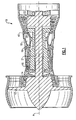
- Figure 1 illustrates a gas turbine engine 10 which may include (in serial flow communication) a fan section 12, a low pressure compressor 14, a high pressure compressor 16, a combustor 18, a high pressure turbine 20 and a low pressure turbine 22.
- a gas turbine engine 10 which may include (in serial flow communication) a fan section 12, a low pressure compressor 14, a high pressure compressor 16, a combustor 18, a high pressure turbine 20 and a low pressure turbine 22.
- air is pulled into the gas turbine engine 10 by the fan section 12, is pressurized by the compressors 14, 16, and is mixed with fuel and burned in the combustor 18.
- Hot combustion gases generated within the combustor 18 flow through the high and low pressure turbines 20, 22, which extract energy from the hot combustion gases.
- the high pressure turbine 20 utilizes the extracted energy from the hot combustion gases to power the high pressure compressor 16 through a high speed shaft 19
- a low pressure turbine 22 utilizes the energy extracted from the hot combustion gases to power the fan section 12 and the low pressure compressor 14 through a low speed shaft 21.
- this invention is not limited to the two spool gas turbine architecture described and may be used with other architectures such as single spool axial designs, a three spool axial design and other architectures. That is, the present invention is applicable to any gas turbine engine, and for any application.
- FIG. 2 illustrates a portion of compressor sections 14, 16 which includes multiple compression stages.
- Each compression stage includes a row of stator vanes 24 (stationary airfoils) followed by a row of rotor blades 26 (moving airfoils).
- the compression stages are circumferentially disposed about an engine centerline axis A. Although only three compression stages are shown, the actual compressor sections 14, 16 could include any number of compression stages.
- the compressor sections 14, 16 also include multiple disks 28 which rotate about engine centerline axis A to rotate the rotor blades 26.
- Each disk 28 includes a disk rim 30.
- Each disk rim supports a plurality of rotor blades 26.
- stator vanes 24 are cantilevered stator vanes. That is, the stator vanes 24 are fixed to an engine casing 40 or other structure at their radial outward end 34 and are unsupported at a radial inward end 36. The radial inward end 36 is directly opposite of the radial outward end 34. An airfoil 25 extends between the opposite ends 34, 36. A tip 38 of the radial inward end 36 of each stator 24 extends adjacent to a rotor seal land 32 which extends between adjacent disk rims 30. The radial outward end 34 is mounted to the engine casing 40 which surrounds the compressor section 14, 16, the combustor section 18, and the turbine sections 20, 22. The tip 38 of each stator 24 may contact the rotor seal land 32 to limit recirculation of airflow within the compressor.
- a clearance X extends in the open space between the tip 38 of each stator 24 and an exterior surface 44 of the rotor seal lands 32. It should be understood that the clearance X is shown significantly larger than actual to better illustrate the interaction between the stator vanes 24 and the rotor seal lands 32. In one example, the clearance X defined between the stator vanes 24 and the rotor seal lands 32 is as close as is possible to zero (i.e., the stator vanes 24 are in perfect contact with the rotor seal lands 32). A worker of ordinary skill in the art having the benefit of this disclosure would be able to design an appropriate clearance X between the stator vanes 24 and the rotor seal lands 32 to achieve maximum efficiency of the gas turbine engine 10.
- the tips 38 of the stator vanes 24 are coated with an abradable material 42. Therefore, the tips 38 are more abradable than the remaining portions of the stator vanes 24 (i.e., the base metal of the stator vanes 24 is less abradable than the abradable material 42).
- the exterior surface 44 of each rotor seal land 32 is coated with an abrasive material 46.
- the abradable material 42 is designed to deteriorate when subjected to friction and the abrasive material 46 is designed to cause irritation to the abradable material 42. Therefore, the abrasive material 46 deteriorates at a slower rate than the abradable material 42.
- the actual thickness of the coatings of the abradable material 42 and the abrasive material 46 will vary based upon design specific parameters including but not limited to the size and type of the gas turbine engine 10.
- the abrasive material 46 is cubic boron nitride.
- the abrasive material is zirconium oxide.
- the zirconium oxide may be a yttria stabilized zirconia.
- the yttria stabilized zirconia includes zirconium oxide stabilized with about 11-14 wt% yttria.
- the yttria stabilized zirconia includes zirconium oxide stabilized with about 6-8 wt% yttria.
- the stabilized zirconium oxide includes zirconium oxide stabilized with about 18.5-21.5 wt% yttria.
- the term "about" as used in this description relative to the compositions refers to possible variations in the compositional percentages, such as normally accepted variations or tolerances in the art.
- the abrasive material is aluminum oxide.
- the abradable material 42 includes zirconium oxide, in one example.
- the abradable material 42 includes the yttria stabilized zirconia. It should be understood that other materials may be utilized for the abradable material 42 and the abrasive material 46. A person of ordinary skill in the art having the benefit of this disclosure would be able to select appropriate materials for use as the abradable material 42 and the abrasive material 46. As can be appreciated by those of skill in the art, the zirconium oxide is capable of use both as the abrasive material 46 and the abradable material 42.
- the zirconium oxide (i.e., the abrasive material 46) applied to the rotor seal land 32 will abrade the zirconium oxide (i.e., the abradable material 42) applied to the tips 38 of the stator vanes 24 in this example.
- the abradable material 42 and the abrasive material 46 are applied by thermal spray.
- the abrasive material 46 includes cubic boron nitride
- the abrasive material 46 is applied by electroplating.
- Other application methods are also contemplated as within the scope of the present invention.
- the abradable material 42 on the tip 38 of each stator 24 and the abrasive material 46 on the rotor seal lands 32 allows the clearance X defined between the stator vanes 24 and the rotor seal lands 32 to be reduced.
- the components of the gas turbine engine 10 may experience thermal expansion, centrifugal loading, and high maneuver loads during high angle of attack, takeoff and landing flight conditions.
- the stator vanes 24 may rub against the rotor seal lands 32 while experiencing conditions of this type.
- the abradable material 42 of the stator vanes 24 rubs against the abrasive material 46 applied on the rotor seal lands 32 causing a portion of the abradable material to turn to harmless fine dust.
- stator vanes 24 are in perfect contact (i.e., line to line contact) with the rotor seal lands 32 during engine operation (See Figure 4 ) to achieve maximum efficiency of the gas turbine engine 10.
- the abradable material 42 coated onto the tips 38 of the stator vanes 24 provides a thermal barrier effect which protects the base metal of the stator vanes 24 from damaging heat. Therefore, the gas turbine engine 10 may be operated at higher temperatures with a reduced risk of damage.
- any other adjacent components of a gas turbine engine including but not limited to turbine stator vanes and components with slider seal type engagements, may include the abradable and abrasive materials to provide tighter clearances and improved rub interactions between the adjacent components at those tighter clearances. That is, the invention is not limited to compressor stator vanes and is applicable to any gas turbine engine component.
Claims (14)
- Gasturbinenmaschine (10) umfassend:eine Mehrzahl von benachbarten Rotorstufen,ein Strömungsprofil (25), das ein radial außen liegendes Ende (34) und ein radial innen liegendes Ende (36) aufweist; undein Dichtungselement (32) benachbart zu dem radial innen liegenden Ende (36) des Strömungsprofils (25), wobei das Dichtungselement (32) mit einem abreibenden Material (46) beschichtet ist undwobei das Dichtungselement (32) einen Rotordichtungssteg beinhaltet, der sich zwischen benachbarten Rotorstufen erstreckt,dadurch gekennzeichnet, dass
eine Spitze (38) des radial innen liegenden Endes (36) des Strömungsprofils mit einem abreibbaren Material (42) beschichtet ist und
das abreibbare Material (42) Zirkoniumoxid beinhaltet, das Yttriumdotiertes Zirkoniumoxid umfasst. - Gasturbinenmaschine (10) nach Anspruch 1, wobei das Strömungsprofil (25) eine Kompressorstator-Leitschaufel ist.
- Gasturbinenmaschine (10) nach Anspruch 1 oder 2, wobei das Strömungsprofil (25) an dem radial außen liegenden Ende (34) zu befestigen ist und das Strömungsprofil (25) an dem radial innen liegenden Ende (36) unbefestigt ist.
- Gasturbinenmaschine (10) nach Anspruch 1, 2 oder 3, wobei das Yttrium-dotierte Zirkoniumoxid 11 Gewichts-% bis 14 Gewichts-% Yttrium aufweist.
- Gasturbinenmaschine (10) nach Anspruch 4, wobei das Yttrium-dotierte Zirkoniumoxid 6 Gewichts-% bis 8 Gewichts-% Yttrium aufweist.
- Gasturbinenmaschine (10) nach Anspruch 1, 2 oder 3, wobei das Yttrium-dotierte Zirkoniumoxid 18,5 Gewichts-% bis 21,5 Gewichts-% Yttrium aufweist.
- Gasturbinenmaschine (10) nach einem der vorangehenden Ansprüche, wobei das abreibende Material (46) zumindest eines aus kubischem Bornitrid, Zirkoniumoxid und Aluminiumoxid beinhaltet.
- Gasturbinenmaschine (10) nach einem der vorangehenden Ansprüche, wobei das Basismetall des Strömungsprofils (25) weniger abreibbar ist als die Beschichtung aus dem abreibbaren Material (42).
- Gasturbinenmaschine (10) nach einem der vorangehenden Ansprüche, umfassend:eine Maschinenummantelung (40), die sich umfangsmäßig um eine Maschinen-Mittellinienachse (A) erstreckt; undeinen Kompressorbereich (14, 16), einen Brennereinrichtungsbereich (18) und einen Turbinenbereich (20, 22) innerhalb der Maschinenummantelung (40), wobei zumindest eines aus dem Kompressorbereich (14, 16) und dem Turbinenbereich (20, 22) zumindest ein Strömungsprofil (25) und zumindest ein Dichtungselement (32) benachbart zu dem zumindest einen Strömungsprofil (25) beinhaltet, wobei eine Spitze (38) des zumindest einen Strömungsprofils (25) mit einem abreibbaren Material (42) beschichtet ist und das zumindest eine Dichtungselement (32) mit einem abreibenden Material (46) beschichtet ist.
- Gasturbinenmaschine (10) nach Anspruch 9, wobei das zumindest eine Strömungsprofil (25) eine Kompressorstator-Leitschaufel (24) beinhaltet.
- Gasturbinenmaschine (10) nach Anspruch 10, wobei das zumindest eine Strömungsprofil (25) eine aus einer Mehrzahl von Kompressorstator-Leitschaufeln (24) beinhaltet, die umfangsmäßig um eine Maschinen-Mittellinienachse (A) zwischen jeweiliger einer Mehrzahl von Reihen von rotierenden Rotorblättern angeordnet ist.
- Gasturbinenmaschine (10) nach Anspruch 11, wobei das zumindest eine Dichtungselement (32) eine Mehrzahl von Rotordichtungsstegen beinhaltet, wobei sich einer der Mehrzahl von Rotordichtungsstegen (32) zwischen jeweiligen der Mehrzahl von Reihen von rotierenden Rotorblättern erstreckt.
- Gasturbinenmaschine (10) nach einem der Ansprüche 9 bis 12, wobei das zumindest eine Strömungsprofil (25) an einem radial außen liegenden Ende (34) an der Maschinenummantelung (40) angebracht ist und die Spitze (38) des zumindest einen Strömungsprofils (25) an einem dem radial außen liegenden Ende gegenüberliegenden Ende des zumindest einen Strömungsprofils (25) angeordnet ist.
- Gasturbinenmaschine (10) nach einem der Ansprüche 9 bis 13, wobei das Basismetall des zumindest einen Strömungsprofils (25) weniger abreibbar ist als die Beschichtung aus dem abreibbaren Material (42).
Applications Claiming Priority (1)
| Application Number | Priority Date | Filing Date | Title |
|---|---|---|---|
| US11/682,048 US8038388B2 (en) | 2007-03-05 | 2007-03-05 | Abradable component for a gas turbine engine |
Publications (2)
| Publication Number | Publication Date |
|---|---|
| EP1967699A1 EP1967699A1 (de) | 2008-09-10 |
| EP1967699B1 true EP1967699B1 (de) | 2012-04-25 |
Family
ID=39477962
Family Applications (1)
| Application Number | Title | Priority Date | Filing Date |
|---|---|---|---|
| EP08250742A Revoked EP1967699B1 (de) | 2007-03-05 | 2008-03-05 | Gasturbinentriebwerk mit einer abschleifbaren Dichtung |
Country Status (3)
| Country | Link |
|---|---|
| US (1) | US8038388B2 (de) |
| EP (1) | EP1967699B1 (de) |
| JP (1) | JP2008215347A (de) |
Cited By (1)
| Publication number | Priority date | Publication date | Assignee | Title |
|---|---|---|---|---|
| US9909428B2 (en) | 2013-11-26 | 2018-03-06 | General Electric Company | Turbine buckets with high hot hardness shroud-cutting deposits |
Families Citing this family (29)
| Publication number | Priority date | Publication date | Assignee | Title |
|---|---|---|---|---|
| FR2940413B1 (fr) * | 2008-12-19 | 2013-01-11 | Air Liquide | Procede de capture du co2 par cryo-condensation |
| DE102009036407A1 (de) * | 2009-08-06 | 2011-02-10 | Mtu Aero Engines Gmbh | Abreibbarer Schaufelspitzenbelag |
| US20110120078A1 (en) * | 2009-11-24 | 2011-05-26 | Schwark Jr Fred W | Variable area fan nozzle track |
| US8443586B2 (en) * | 2009-11-24 | 2013-05-21 | United Technologies Corporation | Variable area fan nozzle bearing track |
| US8727712B2 (en) | 2010-09-14 | 2014-05-20 | United Technologies Corporation | Abradable coating with safety fuse |
| US9169740B2 (en) | 2010-10-25 | 2015-10-27 | United Technologies Corporation | Friable ceramic rotor shaft abrasive coating |
| US8770927B2 (en) | 2010-10-25 | 2014-07-08 | United Technologies Corporation | Abrasive cutter formed by thermal spray and post treatment |
| US20120100299A1 (en) * | 2010-10-25 | 2012-04-26 | United Technologies Corporation | Thermal spray coating process for compressor shafts |
| US8770926B2 (en) | 2010-10-25 | 2014-07-08 | United Technologies Corporation | Rough dense ceramic sealing surface in turbomachines |
| US8790078B2 (en) | 2010-10-25 | 2014-07-29 | United Technologies Corporation | Abrasive rotor shaft ceramic coating |
| US8936432B2 (en) | 2010-10-25 | 2015-01-20 | United Technologies Corporation | Low density abradable coating with fine porosity |
| US20120099992A1 (en) * | 2010-10-25 | 2012-04-26 | United Technologies Corporation | Abrasive rotor coating for forming a seal in a gas turbine engine |
| US9181814B2 (en) * | 2010-11-24 | 2015-11-10 | United Technology Corporation | Turbine engine compressor stator |
| US8807955B2 (en) | 2011-06-30 | 2014-08-19 | United Technologies Corporation | Abrasive airfoil tip |
| US8858167B2 (en) * | 2011-08-18 | 2014-10-14 | United Technologies Corporation | Airfoil seal |
| DE102011081323B3 (de) * | 2011-08-22 | 2012-06-21 | Siemens Aktiengesellschaft | Laufschaufel für eine Strömungsmaschine und Strömungsmaschine mit der Laufschaufel |
| FR2996874B1 (fr) * | 2012-10-11 | 2014-12-19 | Turbomeca | Ensemble rotor-stator pour moteur a turbine a gaz |
| US9598973B2 (en) * | 2012-11-28 | 2017-03-21 | General Electric Company | Seal systems for use in turbomachines and methods of fabricating the same |
| US10107115B2 (en) | 2013-02-05 | 2018-10-23 | United Technologies Corporation | Gas turbine engine component having tip vortex creation feature |
| WO2014158236A1 (en) * | 2013-03-12 | 2014-10-02 | United Technologies Corporation | Cantilever stator with vortex initiation feature |
| US10018061B2 (en) | 2013-03-12 | 2018-07-10 | United Technologies Corporation | Vane tip machining fixture assembly |
| EP2971560B1 (de) * | 2013-03-15 | 2020-05-06 | United Technologies Corporation | Maxmetkomposite für turbinenmotorkomponentenspitzen |
| US9957826B2 (en) | 2014-06-09 | 2018-05-01 | United Technologies Corporation | Stiffness controlled abradeable seal system with max phase materials and methods of making same |
| EP3177811B1 (de) | 2014-08-08 | 2021-07-21 | Siemens Energy Global GmbH & Co. KG | Gasturbinen verdichter |
| US10036263B2 (en) | 2014-10-22 | 2018-07-31 | United Technologies Corporation | Stator assembly with pad interface for a gas turbine engine |
| US20160122552A1 (en) * | 2014-10-31 | 2016-05-05 | United Technologies Corporation | Abrasive Rotor Coating With Rub Force Limiting Features |
| EP3440318B1 (de) * | 2016-04-08 | 2021-06-02 | Raytheon Technologies Corporation | Dichtungsgeometrien für reduzierte leckage in gasturbinen und verfahren zur formung |
| US10344614B2 (en) | 2016-04-12 | 2019-07-09 | United Technologies Corporation | Active clearance control for a turbine and case |
| US20240102395A1 (en) * | 2022-09-27 | 2024-03-28 | Pratt & Whitney Canada Corp. | Stator vane for a gas turbine engine |
Citations (3)
| Publication number | Priority date | Publication date | Assignee | Title |
|---|---|---|---|---|
| GB2139114A (en) * | 1981-11-02 | 1984-11-07 | United Technologies Corp | Co-spray abrasive coating |
| US5705231A (en) * | 1995-09-26 | 1998-01-06 | United Technologies Corporation | Method of producing a segmented abradable ceramic coating system |
| EP1555392A2 (de) * | 2004-01-13 | 2005-07-20 | ROLLS-ROYCE plc | Freitragende Statorstufe |
Family Cites Families (51)
| Publication number | Priority date | Publication date | Assignee | Title |
|---|---|---|---|---|
| GB902645A (en) | 1957-11-26 | 1962-08-09 | Bristol Siddeley Engines Ltd | Improvements in turbines, rotary compressors and the like |
| US4094673A (en) * | 1974-02-28 | 1978-06-13 | Brunswick Corporation | Abradable seal material and composition thereof |
| US4218066A (en) * | 1976-03-23 | 1980-08-19 | United Technologies Corporation | Rotary seal |
| US4238170A (en) * | 1978-06-26 | 1980-12-09 | United Technologies Corporation | Blade tip seal for an axial flow rotary machine |
| US4274805A (en) * | 1978-10-02 | 1981-06-23 | United Technologies Corporation | Floating vane support |
| US4592204A (en) * | 1978-10-26 | 1986-06-03 | Rice Ivan G | Compression intercooled high cycle pressure ratio gas generator for combined cycles |
| US4896499A (en) * | 1978-10-26 | 1990-01-30 | Rice Ivan G | Compression intercooled gas turbine combined cycle |
| US4311431A (en) * | 1978-11-08 | 1982-01-19 | Teledyne Industries, Inc. | Turbine engine with shroud cooling means |
| US4314173A (en) * | 1980-04-10 | 1982-02-02 | Westinghouse Electric Corp. | Mounting bracket for bracing peripheral connecting rings for dynamoelectric machines' stator windings |
| US4395195A (en) * | 1980-05-16 | 1983-07-26 | United Technologies Corporation | Shroud ring for use in a gas turbine engine |
| US4553901A (en) * | 1983-12-21 | 1985-11-19 | United Technologies Corporation | Stator structure for a gas turbine engine |
| GB2207191B (en) | 1987-07-06 | 1992-03-04 | Gen Electric | Gas turbine engine |
| US4936745A (en) | 1988-12-16 | 1990-06-26 | United Technologies Corporation | Thin abradable ceramic air seal |
| US5536022A (en) * | 1990-08-24 | 1996-07-16 | United Technologies Corporation | Plasma sprayed abradable seals for gas turbine engines |
| US5282718A (en) * | 1991-01-30 | 1994-02-01 | United Technologies Corporation | Case treatment for compressor blades |
| EP0497574B1 (de) * | 1991-01-30 | 1995-09-20 | United Technologies Corporation | Ventilatorgehäuse mit Rezirculationskanälen |
| US5314304A (en) * | 1991-08-15 | 1994-05-24 | The United States Of America As Represented By The Secretary Of The Air Force | Abradeable labyrinth stator seal |
| FR2683002B1 (fr) * | 1991-10-23 | 1993-12-17 | Snecma | Compresseur axial adapte a la maintenance et son procede de maintenance. |
| US5205115A (en) * | 1991-11-04 | 1993-04-27 | General Electric Company | Gas turbine engine case counterflow thermal control |
| US5219268A (en) * | 1992-03-06 | 1993-06-15 | General Electric Company | Gas turbine engine case thermal control flange |
| US5261228A (en) * | 1992-06-25 | 1993-11-16 | General Electric Company | Apparatus for bleeding air |
| US5267435A (en) * | 1992-08-18 | 1993-12-07 | General Electric Company | Thrust droop compensation method and system |
| US5361580A (en) * | 1993-06-18 | 1994-11-08 | General Electric Company | Gas turbine engine rotor support system |
| US5443590A (en) | 1993-06-18 | 1995-08-22 | General Electric Company | Rotatable turbine frame |
| US5307622A (en) * | 1993-08-02 | 1994-05-03 | General Electric Company | Counterrotating turbine support assembly |
| US5562404A (en) * | 1994-12-23 | 1996-10-08 | United Technologies Corporation | Vaned passage hub treatment for cantilever stator vanes |
| GB2310255B (en) | 1996-02-13 | 1999-06-16 | Rolls Royce Plc | A turbomachine |
| US5932356A (en) * | 1996-03-21 | 1999-08-03 | United Technologies Corporation | Abrasive/abradable gas path seal system |
| US5704759A (en) | 1996-10-21 | 1998-01-06 | Alliedsignal Inc. | Abrasive tip/abradable shroud system and method for gas turbine compressor clearance control |
| US6190124B1 (en) * | 1997-11-26 | 2001-02-20 | United Technologies Corporation | Columnar zirconium oxide abrasive coating for a gas turbine engine seal system |
| SG72959A1 (en) * | 1998-06-18 | 2000-05-23 | United Technologies Corp | Article having durable ceramic coating with localized abradable portion |
| US6089825A (en) * | 1998-12-18 | 2000-07-18 | United Technologies Corporation | Abradable seal having improved properties and method of producing seal |
| US6267553B1 (en) * | 1999-06-01 | 2001-07-31 | Joseph C. Burge | Gas turbine compressor spool with structural and thermal upgrades |
| DE10020673C2 (de) * | 2000-04-27 | 2002-06-27 | Mtu Aero Engines Gmbh | Ringstruktur in Metallbauweise |
| EP1205639A1 (de) | 2000-11-09 | 2002-05-15 | General Electric Company | Befestigungsanordnung von verstellbaren Turbinenleitschaufeln im inneren Haltering |
| DE10121019A1 (de) * | 2001-04-28 | 2002-10-31 | Alstom Switzerland Ltd | Gasturbinendichtung |
| GB0113700D0 (en) * | 2001-06-06 | 2001-07-25 | Evolving Generation Ltd | Electrical machine and rotor therefor |
| FR2825748B1 (fr) * | 2001-06-07 | 2003-11-07 | Snecma Moteurs | Agencement de rotor de turbomachine a deux disques aubages separes par une entretoise |
| US6619030B1 (en) | 2002-03-01 | 2003-09-16 | General Electric Company | Aircraft engine with inter-turbine engine frame supported counter rotating low pressure turbine rotors |
| US7291946B2 (en) * | 2003-01-27 | 2007-11-06 | United Technologies Corporation | Damper for stator assembly |
| EP1777378A3 (de) | 2003-07-29 | 2011-03-09 | Pratt & Whitney Canada Corp. | Gehäuse für ein Mantelstromtriebwerk und Herstellungsverfahren dafür |
| US7370467B2 (en) * | 2003-07-29 | 2008-05-13 | Pratt & Whitney Canada Corp. | Turbofan case and method of making |
| US6905302B2 (en) * | 2003-09-17 | 2005-06-14 | General Electric Company | Network cooled coated wall |
| FR2875866B1 (fr) * | 2004-09-30 | 2006-12-08 | Snecma Moteurs Sa | Procede de circulation d'air dans un compresseur de turbomachine, agencement de compresseur le mettant en oeuvre , etage de compression et compresseur comportant un tel agencement, et moteur d'aeronef equipe d'un tel compresseur |
| US7287956B2 (en) * | 2004-12-22 | 2007-10-30 | General Electric Company | Removable abradable seal carriers for sealing between rotary and stationary turbine components |
| US7470113B2 (en) * | 2006-06-22 | 2008-12-30 | United Technologies Corporation | Split knife edge seals |
| US7448843B2 (en) * | 2006-07-05 | 2008-11-11 | United Technologies Corporation | Rotor for jet turbine engine having both insulation and abrasive material coatings |
| GB0613715D0 (en) | 2006-07-11 | 2006-08-23 | Rolls Royce Plc | A seal between relatively moveable members |
| US7604455B2 (en) * | 2006-08-15 | 2009-10-20 | Siemens Energy, Inc. | Rotor disc assembly with abrasive insert |
| US8017240B2 (en) * | 2006-09-28 | 2011-09-13 | United Technologies Corporation | Ternary carbide and nitride thermal spray abradable seal material |
| US20090072487A1 (en) * | 2007-09-18 | 2009-03-19 | Honeywell International, Inc. | Notched tooth labyrinth seals and methods of manufacture |
-
2007
- 2007-03-05 US US11/682,048 patent/US8038388B2/en active Active
-
2008
- 2008-02-26 JP JP2008043700A patent/JP2008215347A/ja active Pending
- 2008-03-05 EP EP08250742A patent/EP1967699B1/de not_active Revoked
Patent Citations (3)
| Publication number | Priority date | Publication date | Assignee | Title |
|---|---|---|---|---|
| GB2139114A (en) * | 1981-11-02 | 1984-11-07 | United Technologies Corp | Co-spray abrasive coating |
| US5705231A (en) * | 1995-09-26 | 1998-01-06 | United Technologies Corporation | Method of producing a segmented abradable ceramic coating system |
| EP1555392A2 (de) * | 2004-01-13 | 2005-07-20 | ROLLS-ROYCE plc | Freitragende Statorstufe |
Cited By (1)
| Publication number | Priority date | Publication date | Assignee | Title |
|---|---|---|---|---|
| US9909428B2 (en) | 2013-11-26 | 2018-03-06 | General Electric Company | Turbine buckets with high hot hardness shroud-cutting deposits |
Also Published As
| Publication number | Publication date |
|---|---|
| JP2008215347A (ja) | 2008-09-18 |
| US8038388B2 (en) | 2011-10-18 |
| US20080219835A1 (en) | 2008-09-11 |
| EP1967699A1 (de) | 2008-09-10 |
Similar Documents
| Publication | Publication Date | Title |
|---|---|---|
| EP1967699B1 (de) | Gasturbinentriebwerk mit einer abschleifbaren Dichtung | |
| EP2851511B1 (de) | Turbinenschaufeln mit Schaufelspitzenbschnitten mit konvergierenden Kühllöchern | |
| EP2689108B1 (de) | Verdichterschaufel mit spitzen-v-form | |
| JP3789131B2 (ja) | 翼端リーク流を制御した動翼 | |
| EP2369138B1 (de) | Gasturbinenmotor mit nicht-axialsymmetrischer, oberflächenkonturierter Schaufelplattform | |
| EP3150803B1 (de) | Schaufelprofil und kühlverfahren | |
| EP3183428B1 (de) | Verdichterschaufel | |
| US9284845B2 (en) | Turbine airfoil tip shelf and squealer pocket cooling | |
| EP2863015B1 (de) | Turbinenlaufschaufel und zugehöriges herstellungsverfahren | |
| EP2644836B1 (de) | Gasturbinenanordnung mit effusionsgekühltem Mantelringsegment mit einer abreibbaren Beschichtung | |
| US10677066B2 (en) | Turbine blade with airfoil tip vortex control | |
| EP2372102A2 (de) | Laufschaufelplattform einer Gasturbine | |
| EP2540979A2 (de) | Rotoranordnung und umkehrbare Turbinenschaufelhaltevorrichtung dafür | |
| US20180230839A1 (en) | Turbine engine shroud assembly | |
| US10280841B2 (en) | Baffle insert for a gas turbine engine component and method of cooling | |
| CN109416050B (zh) | 具有分流器叶片的轴流式压缩机 | |
| EP2639410A2 (de) | In-situ Spielsteuerung zwischen Gasturbinenlaufschaufel und Gehäuse | |
| EP3170974A1 (de) | Turbinenschaufel mit spitzenwirbelverminderung | |
| US20210372288A1 (en) | Compressor stator with leading edge fillet | |
| WO2020101774A1 (en) | Improved first stage turbine nozzle | |
| US20180328207A1 (en) | Gas turbine engine component having tip vortex creation feature | |
| US11788415B2 (en) | Shroudless blade for a high-speed turbine stage | |
| EP3722555B1 (de) | Turbinenabschnitt umfassend nicht axialsymmetrische endwandkonturierung mit vorderer mittelpassagenspitze | |
| JP5770970B2 (ja) | ガスタービンエンジン用タービンノズル | |
| WO2013172903A2 (en) | Tapered thermal coating for airfoil |
Legal Events
| Date | Code | Title | Description |
|---|---|---|---|
| PUAI | Public reference made under article 153(3) epc to a published international application that has entered the european phase |
Free format text: ORIGINAL CODE: 0009012 |
|
| AK | Designated contracting states |
Kind code of ref document: A1 Designated state(s): AT BE BG CH CY CZ DE DK EE ES FI FR GB GR HR HU IE IS IT LI LT LU LV MC MT NL NO PL PT RO SE SI SK TR |
|
| AX | Request for extension of the european patent |
Extension state: AL BA MK RS |
|
| 17P | Request for examination filed |
Effective date: 20081215 |
|
| 17Q | First examination report despatched |
Effective date: 20090121 |
|
| AKX | Designation fees paid |
Designated state(s): DE GB |
|
| GRAP | Despatch of communication of intention to grant a patent |
Free format text: ORIGINAL CODE: EPIDOSNIGR1 |
|
| GRAS | Grant fee paid |
Free format text: ORIGINAL CODE: EPIDOSNIGR3 |
|
| GRAA | (expected) grant |
Free format text: ORIGINAL CODE: 0009210 |
|
| STAA | Information on the status of an ep patent application or granted ep patent |
Free format text: STATUS: THE PATENT HAS BEEN GRANTED |
|
| AK | Designated contracting states |
Kind code of ref document: B1 Designated state(s): DE GB |
|
| REG | Reference to a national code |
Ref country code: GB Ref legal event code: FG4D |
|
| REG | Reference to a national code |
Ref country code: DE Ref legal event code: R096 Ref document number: 602008015158 Country of ref document: DE Effective date: 20120621 |
|
| PLBI | Opposition filed |
Free format text: ORIGINAL CODE: 0009260 |
|
| 26 | Opposition filed |
Opponent name: SIEMENS AG Effective date: 20121203 |
|
| REG | Reference to a national code |
Ref country code: DE Ref legal event code: R026 Ref document number: 602008015158 Country of ref document: DE Effective date: 20121203 |
|
| PLAX | Notice of opposition and request to file observation + time limit sent |
Free format text: ORIGINAL CODE: EPIDOSNOBS2 |
|
| PLAF | Information modified related to communication of a notice of opposition and request to file observations + time limit |
Free format text: ORIGINAL CODE: EPIDOSCOBS2 |
|
| PLBB | Reply of patent proprietor to notice(s) of opposition received |
Free format text: ORIGINAL CODE: EPIDOSNOBS3 |
|
| RAP2 | Party data changed (patent owner data changed or rights of a patent transferred) |
Owner name: UNITED TECHNOLOGIES CORPORATION |
|
| PLCK | Communication despatched that opposition was rejected |
Free format text: ORIGINAL CODE: EPIDOSNREJ1 |
|
| STAA | Information on the status of an ep patent application or granted ep patent |
Free format text: STATUS: THE PATENT HAS BEEN GRANTED |
|
| APBM | Appeal reference recorded |
Free format text: ORIGINAL CODE: EPIDOSNREFNO |
|
| APBP | Date of receipt of notice of appeal recorded |
Free format text: ORIGINAL CODE: EPIDOSNNOA2O |
|
| APAH | Appeal reference modified |
Free format text: ORIGINAL CODE: EPIDOSCREFNO |
|
| APBQ | Date of receipt of statement of grounds of appeal recorded |
Free format text: ORIGINAL CODE: EPIDOSNNOA3O |
|
| REG | Reference to a national code |
Ref country code: DE Ref legal event code: R082 Ref document number: 602008015158 Country of ref document: DE Representative=s name: SCHMITT-NILSON SCHRAUD WAIBEL WOHLFROM PATENTA, DE |
|
| REG | Reference to a national code |
Ref country code: DE Ref legal event code: R082 Ref document number: 602008015158 Country of ref document: DE Representative=s name: SCHMITT-NILSON SCHRAUD WAIBEL WOHLFROM PATENTA, DE Ref country code: DE Ref legal event code: R081 Ref document number: 602008015158 Country of ref document: DE Owner name: UNITED TECHNOLOGIES CORP. (N.D.GES.D. STAATES , US Free format text: FORMER OWNER: UNITED TECHNOLOGIES CORPORATION, HARTFORD, CONN., US |
|
| PLAB | Opposition data, opponent's data or that of the opponent's representative modified |
Free format text: ORIGINAL CODE: 0009299OPPO |
|
| R26 | Opposition filed (corrected) |
Opponent name: SIEMENS AKTIENGESELLSCHAFT Effective date: 20121203 |
|
| RAP2 | Party data changed (patent owner data changed or rights of a patent transferred) |
Owner name: RAYTHEON TECHNOLOGIES CORPORATION |
|
| PLAB | Opposition data, opponent's data or that of the opponent's representative modified |
Free format text: ORIGINAL CODE: 0009299OPPO |
|
| R26 | Opposition filed (corrected) |
Opponent name: SIEMENS AKTIENGESELLSCHAFT Effective date: 20121203 |
|
| PGFP | Annual fee paid to national office [announced via postgrant information from national office to epo] |
Ref country code: DE Payment date: 20210217 Year of fee payment: 14 Ref country code: GB Payment date: 20210219 Year of fee payment: 14 |
|
| REG | Reference to a national code |
Ref country code: DE Ref legal event code: R103 Ref document number: 602008015158 Country of ref document: DE Ref country code: DE Ref legal event code: R064 Ref document number: 602008015158 Country of ref document: DE |
|
| APBU | Appeal procedure closed |
Free format text: ORIGINAL CODE: EPIDOSNNOA9O |
|
| RDAF | Communication despatched that patent is revoked |
Free format text: ORIGINAL CODE: EPIDOSNREV1 |
|
| STAA | Information on the status of an ep patent application or granted ep patent |
Free format text: STATUS: PATENT REVOKED |
|
| RDAG | Patent revoked |
Free format text: ORIGINAL CODE: 0009271 |
|
| 27W | Patent revoked |
Effective date: 20211028 |
|
| GBPR | Gb: patent revoked under art. 102 of the ep convention designating the uk as contracting state |
Effective date: 20211028 |