EP1967655A2 - Excavator bucket and crusher for a loader or excavator - Google Patents
Excavator bucket and crusher for a loader or excavator Download PDFInfo
- Publication number
- EP1967655A2 EP1967655A2 EP08151792A EP08151792A EP1967655A2 EP 1967655 A2 EP1967655 A2 EP 1967655A2 EP 08151792 A EP08151792 A EP 08151792A EP 08151792 A EP08151792 A EP 08151792A EP 1967655 A2 EP1967655 A2 EP 1967655A2
- Authority
- EP
- European Patent Office
- Prior art keywords
- crusher
- excavator bucket
- excavator
- crushing mechanism
- projections
- Prior art date
- Legal status (The legal status is an assumption and is not a legal conclusion. Google has not performed a legal analysis and makes no representation as to the accuracy of the status listed.)
- Withdrawn
Links
- 230000000295 complement effect Effects 0.000 claims description 7
- 230000008878 coupling Effects 0.000 claims description 4
- 238000010168 coupling process Methods 0.000 claims description 4
- 238000005859 coupling reaction Methods 0.000 claims description 4
- 230000002787 reinforcement Effects 0.000 claims description 3
- 238000009412 basement excavation Methods 0.000 abstract description 2
- 239000000463 material Substances 0.000 description 8
- 238000010276 construction Methods 0.000 description 2
- 239000000945 filler Substances 0.000 description 1
- 239000004575 stone Substances 0.000 description 1
Images


Classifications
-
- E—FIXED CONSTRUCTIONS
- E02—HYDRAULIC ENGINEERING; FOUNDATIONS; SOIL SHIFTING
- E02F—DREDGING; SOIL-SHIFTING
- E02F3/00—Dredgers; Soil-shifting machines
- E02F3/04—Dredgers; Soil-shifting machines mechanically-driven
- E02F3/28—Dredgers; Soil-shifting machines mechanically-driven with digging tools mounted on a dipper- or bucket-arm, i.e. there is either one arm or a pair of arms, e.g. dippers, buckets
- E02F3/36—Component parts
- E02F3/40—Dippers; Buckets ; Grab devices, e.g. manufacturing processes for buckets, form, geometry or material of buckets
- E02F3/402—Dippers; Buckets ; Grab devices, e.g. manufacturing processes for buckets, form, geometry or material of buckets with means for facilitating the loading thereof, e.g. conveyors
- E02F3/404—Dippers; Buckets ; Grab devices, e.g. manufacturing processes for buckets, form, geometry or material of buckets with means for facilitating the loading thereof, e.g. conveyors comprising two parts movable relative to each other, e.g. for gripping
-
- B—PERFORMING OPERATIONS; TRANSPORTING
- B02—CRUSHING, PULVERISING, OR DISINTEGRATING; PREPARATORY TREATMENT OF GRAIN FOR MILLING
- B02C—CRUSHING, PULVERISING, OR DISINTEGRATING IN GENERAL; MILLING GRAIN
- B02C1/00—Crushing or disintegrating by reciprocating members
- B02C1/02—Jaw crushers or pulverisers
- B02C1/04—Jaw crushers or pulverisers with single-acting jaws
-
- B—PERFORMING OPERATIONS; TRANSPORTING
- B02—CRUSHING, PULVERISING, OR DISINTEGRATING; PREPARATORY TREATMENT OF GRAIN FOR MILLING
- B02C—CRUSHING, PULVERISING, OR DISINTEGRATING IN GENERAL; MILLING GRAIN
- B02C1/00—Crushing or disintegrating by reciprocating members
- B02C1/02—Jaw crushers or pulverisers
- B02C1/10—Shape or construction of jaws
-
- E—FIXED CONSTRUCTIONS
- E02—HYDRAULIC ENGINEERING; FOUNDATIONS; SOIL SHIFTING
- E02F—DREDGING; SOIL-SHIFTING
- E02F3/00—Dredgers; Soil-shifting machines
- E02F3/04—Dredgers; Soil-shifting machines mechanically-driven
- E02F3/28—Dredgers; Soil-shifting machines mechanically-driven with digging tools mounted on a dipper- or bucket-arm, i.e. there is either one arm or a pair of arms, e.g. dippers, buckets
- E02F3/36—Component parts
- E02F3/40—Dippers; Buckets ; Grab devices, e.g. manufacturing processes for buckets, form, geometry or material of buckets
- E02F3/402—Dippers; Buckets ; Grab devices, e.g. manufacturing processes for buckets, form, geometry or material of buckets with means for facilitating the loading thereof, e.g. conveyors
- E02F3/405—Dippers; Buckets ; Grab devices, e.g. manufacturing processes for buckets, form, geometry or material of buckets with means for facilitating the loading thereof, e.g. conveyors using vibrating means
-
- E—FIXED CONSTRUCTIONS
- E02—HYDRAULIC ENGINEERING; FOUNDATIONS; SOIL SHIFTING
- E02F—DREDGING; SOIL-SHIFTING
- E02F3/00—Dredgers; Soil-shifting machines
- E02F3/04—Dredgers; Soil-shifting machines mechanically-driven
- E02F3/96—Dredgers; Soil-shifting machines mechanically-driven with arrangements for alternate or simultaneous use of different digging elements
- E02F3/965—Dredgers; Soil-shifting machines mechanically-driven with arrangements for alternate or simultaneous use of different digging elements of metal-cutting or concrete-crushing implements
-
- E—FIXED CONSTRUCTIONS
- E04—BUILDING
- E04G—SCAFFOLDING; FORMS; SHUTTERING; BUILDING IMPLEMENTS OR AIDS, OR THEIR USE; HANDLING BUILDING MATERIALS ON THE SITE; REPAIRING, BREAKING-UP OR OTHER WORK ON EXISTING BUILDINGS
- E04G23/00—Working measures on existing buildings
- E04G23/08—Wrecking of buildings
- E04G23/082—Wrecking of buildings using shears, breakers, jaws and the like
Definitions
- the present invention concerns an excavator bucket and crusher for a loader or excavator and of the kind specified in the preamble of claim 1.
- Prior art excavator buckets and crushers are very large and complicated tools requiring very large and space-consuming loaders or excavators which additionally are very expensive in acquisition and service.
- the excavator bucket and crusher is characterised in that the movable part of the crushing mechanism includes gripping means arranged to grip and clamp an object which is to be picked up for crushing by means of the crushing mechanism, and that the stationary part of the crushing mechanism is constituted by a grating-shaped wall section of the excavator bucket and crusher.
- the excavator bucket and crusher according to the invention may be suitably designed so that the stationary part of the crushing mechanism is designed with rows of tooth-like projections, and that the movable part of the crushing mechanism is also designed with rows of tooth-like projections arranged to engage the tooth-like projections of the stationary part of the crushing mechanism, as respective tooth-like projections of respective parts of the crushing mechanism are mutually complementary in position, i.e. engaging between and with each other.
- the excavator bucket and crusher according to the invention may advantageously be further designed so that the tooth-like projections on the stationary, grate-shaped open wall section of the excavator bucket are narrow and mutually spaced apart so that the tooth-like projections of the movable part of the crushing mechanism may be inserted between the narrow projections of the stationary grate-shaped wall section of the excavator bucket and crusher.
- the excavator bucket and crusher according to the invention may be designed so that the tooth-like narrow projections of the stationary part of the excavator bucket and crusher are designed with transverse grooves.
- the excavator bucket and crusher according to the invention may be designed so that the said stationary part of the crusher mechanism is constituted by a plate-shaped wall section of the excavator bucket, the wall section including a convex, curving, plate-shaped reinforcement which is designed with rows of tooth-like projections that positionally are complementary to rows of tooth-like projections of the movable part of the crushing mechanism.
- the excavator bucket and crusher is closed downwards by means of a plate-shaped wall section constituting the stationary part of the crushing mechanism, so that it becomes easier to control the discharge of crushed material from the crushing mechanism.
- the discharge of crushed material may hereby e.g. be loaded more easily into a container constituting a temporary depot, as the crushed material - as mentioned in the introduction - according to official requirements is to be recycled to the greatest possible extent at the demolition site as filler material at the construction of new buildings replacing demolished buildings.
- the excavator bucket and crusher according to the invention is suitably designed so that the crushing mechanism is drivingly connected with or includes two hydraulic cylinders which are disposed with mutually spacing at each their side of the excavator bucket and crusher.
- this may suitably designed with a socket part adapted to interact with a fast-action coupling disposed at the said extreme end of the excavator arm.
- the excavator bucket and crusher according to the invention may advantageously be designed so as to include a vibrator mechanism mounted either at the stationary part or the movable part of the crushing mechanism.
- the excavator bucket and crusher according to the invention may in an optimal way be designed so that vibrator mechanism is constituted by a hydraulic vibrator which is effectively connected with the movable part of the crushing mechanism.
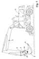
- FIG. 1 An embodiment of a combined excavator bucket and crusher 2 is shown in Fig. 1 , where the excavator bucket and crusher 2 is mounted by means of a fast-action coupling 4 at the extreme end 6 of an articulated excavator arm 8 of an medium-sized excavator 10.
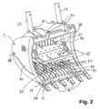
- the excavator bucket and crusher 2 cf. Fig. 1 , is shown separately in Figs. 2-4 , in which it clearly appears that the excavator bucket and crusher 2 is predominantly designed as a common medium-sized excavator bucket where a stationary part 11 of a crushing mechanism 12 is constituted by a grate-shaped wall 14 of the excavator bucket and crusher 2 which is provided with standard digging teeth 16 and connecting parts 18, 20 adapted for connecting the excavator bucket and crusher 2 with the fast-action coupling 4 so that the excavator bucket and crusher 2 may be rapidly substituted by another tool.
- the crushing mechanism 12 is driven by two hydraulic cylinders 22 and includes a movable part 24 which by means of plate-shaped pivoting arms 26 are pivotably suspended about a transverse axis of pivot 28 arranged between sidewalls 30 of the excavator bucket and crusher 2.
- the movable part 24 is provided along a free outer edge 32 with projecting gripping means 34 intended for use in picking up objects to be crushed by means of the excavator bucket and crusher 2, as such a crushing object is jammed between the stationary part 11, i.e. the grate-shaped wall 14 and the gripping means 34, before the excavator bucket and crusher 2 is pivoted upwards to a position where its opening is predominantly facing upwards, so that the crushing object is brought in place between respective active parts of the crushing mechanism 12, after which the latter is activated by means of the hydraulic cylinders 22 so that crushing object or objects are crushed before discharge from the excavator bucket and crusher 2 through the grate-shaped wall 14. It may be necessary to activate the crushing mechanism several times until the crushing object has been comminuted so much that all parts thereof can pass out through the grate-shaped wall 14.
- movable part 24 is provided with rows of tooth-like projections 36 which by disposition are complementary to projections 38 on single plate slats 40 of the grate-shaped wall 14.
- the grate-shaped wall 14 of the excavator bucket and crusher 2 includes strong transverse rods 42 that run through the slats 40 and which are connected with these and with the sidewalls 30 of the bucket.
- the projections 38 on the slats 40 are disposed opposite the tooth-like projections 36 of the movable part 24 so that these positionally complementary parts contribute to make efficient the crushing action of the excavator bucket and crusher 2.
- the excavator bucket and crusher 2 may advantageously - as shown with punctuated lines in Fig. 4 - be provided with a preferably hydraulic vibrating mechanism 58 which has been fitted upon the bucket between the hydraulic cylinders 22, and which via an actuator arm 60 is effectively connected with the movable part 24 of the crushing mechanism 12.
- a hydraulic vibration mechanism may be placed inside the excavator bucket and crusher 2 directly on top of the movable part 24 of the crushing mechanism 12.
- Fig. 5 an alternative embodiment of a excavator bucket and crusher 44 which instead of the grate-shaped wall 14 is provided with a closed plate-shaped wall 46 which opposite tooth-like projections 48 of a movable part 50 is provided with a convex, curving reinforcement plate 52 provided with tooth-like projections 54 which positionally are complementary to the projections 48, i.e. may interact with these with the intention of making efficient the crushing action of the excavator bucket and crusher 44.
- the movable part 50 is provided with gripping means 56 which are intended for use in collecting crushing objects which thereby may be clamped between the gripping means 56 and the stationary part in the form of the closed plate-shaped wall 46.
- gripping means 56 which are intended for use in collecting crushing objects which thereby may be clamped between the gripping means 56 and the stationary part in the form of the closed plate-shaped wall 46.
- identical parts of the excavator bucket and crushers 2 and 44, respectively, are provided with identical reference terms.
Abstract
An excavator bucket and crusher (2) for a loader or excavator (10), adapted for being mounted at an extreme end (6) of a articulated excavator arm (8) of the excavator or loader (10), the excavator bucket and crusher (2) including a crushing mechanism (12) with a stationary part (11) and a movable part (24) which is pivotably suspended in relation to the stationary part (11), and which is drivingly connected with one or more hydraulic cylinders (22), wherein the movable part (24) of the crushing mechanism (12) includes gripping means (34) arranged to grip and clamp an object which is to be picked up for crushing by means of the crushing mechanism (12), and that the stationary part (11) of the crushing mechanism (12) is constituted by a grating-shaped wall section (14) of the excavator bucket and crusher (2). By means of simple technical measures there is hereby enabled an efficient three-in-one excavator bucket and crusher that optionally may be used for excavation, crushing or sorting work and which is particularly suited for work in densely populated areas, as it may be handled by a small or intermediately sized loader or excavator.
Description
- The present invention concerns an excavator bucket and crusher for a loader or excavator and of the kind specified in the preamble of claim 1.
- By demolition works it is expected in the future that official requirements will be encountered more often prohibiting moving away demolished material from the construction site, and which instead is to be reused on the spot. In the UK and in the Netherlands, for example, these kind of requirements are already established by the authorities when the case is demolition and/or enlargement of buildings in densely populated areas, i.e. in particular urban areas.
- Prior art excavator buckets and crushers are very large and complicated tools requiring very large and space-consuming loaders or excavators which additionally are very expensive in acquisition and service.
- On this background, it is the object of the invention to indicate a new and improved excavator bucket and crusher for a loader or excavator of the kind indicated in the introduction, and which by means of simple technical measures enables achieving a very efficient excavator bucket and crusher which is particularly suited for work in densely populated areas, and which may be handled by a small or medium-sized loader or excavator.
- The excavator bucket and crusher is characterised in that the movable part of the crushing mechanism includes gripping means arranged to grip and clamp an object which is to be picked up for crushing by means of the crushing mechanism, and that the stationary part of the crushing mechanism is constituted by a grating-shaped wall section of the excavator bucket and crusher.
- By means of simple technical measures there is hereby enabled achieving a very efficient excavator bucket and crusher which is particularly suited for work in densely populated areas, as it may be handled by a small or medium-sized loader or excavator.
- In other words, we are speaking of a three-in-one excavator bucket and crusher that optionally may be used for excavation, crushing or sorting work. By crushing and sorting work it is at the same time possible to achieve a rapid and efficient emptying of crushed material as the stationary part of the crushing mechanism is constituted by a grate-shaped, open wall section of the stationary part of the excavator bucket and crusher.
- With the intention of making efficient the crushing mechanism itself, the excavator bucket and crusher according to the invention may be suitably designed so that the stationary part of the crushing mechanism is designed with rows of tooth-like projections, and that the movable part of the crushing mechanism is also designed with rows of tooth-like projections arranged to engage the tooth-like projections of the stationary part of the crushing mechanism, as respective tooth-like projections of respective parts of the crushing mechanism are mutually complementary in position, i.e. engaging between and with each other.
- With the intention of achieving an efficient comminution of the crushed material, the excavator bucket and crusher according to the invention may advantageously be further designed so that the tooth-like projections on the stationary, grate-shaped open wall section of the excavator bucket are narrow and mutually spaced apart so that the tooth-like projections of the movable part of the crushing mechanism may be inserted between the narrow projections of the stationary grate-shaped wall section of the excavator bucket and crusher.
- In order to make efficient the gripping action when picking up stone or concrete objects to be crushed, the excavator bucket and crusher according to the invention may be designed so that the tooth-like narrow projections of the stationary part of the excavator bucket and crusher are designed with transverse grooves.
- In an alternative embodiment, the excavator bucket and crusher according to the invention may be designed so that the said stationary part of the crusher mechanism is constituted by a plate-shaped wall section of the excavator bucket, the wall section including a convex, curving, plate-shaped reinforcement which is designed with rows of tooth-like projections that positionally are complementary to rows of tooth-like projections of the movable part of the crushing mechanism.
- In some situations it may be advantageous that the excavator bucket and crusher is closed downwards by means of a plate-shaped wall section constituting the stationary part of the crushing mechanism, so that it becomes easier to control the discharge of crushed material from the crushing mechanism.
- In practice, the discharge of crushed material may hereby e.g. be loaded more easily into a container constituting a temporary depot, as the crushed material - as mentioned in the introduction - according to official requirements is to be recycled to the greatest possible extent at the demolition site as filler material at the construction of new buildings replacing demolished buildings.
- The excavator bucket and crusher according to the invention is suitably designed so that the crushing mechanism is drivingly connected with or includes two hydraulic cylinders which are disposed with mutually spacing at each their side of the excavator bucket and crusher.
- With the intention of rapid mounting and dismounting of the excavator bucket and crusher according to the invention, this may suitably designed with a socket part adapted to interact with a fast-action coupling disposed at the said extreme end of the excavator arm.
- With the object of making the excavator bucket and crusher according to the invention more efficient, it may advantageously be designed so as to include a vibrator mechanism mounted either at the stationary part or the movable part of the crushing mechanism.
- The excavator bucket and crusher according to the invention may in an optimal way be designed so that vibrator mechanism is constituted by a hydraulic vibrator which is effectively connected with the movable part of the crushing mechanism.
- The invention is explained in more detail below in connection with the drawing, on which:
- Fig. 1
- shows a plan view of an embodiment of an excavator bucket and crusher according to the invention, shown mounted at an extreme end of an articulated excavator arm of an excavator;
- Fig. 2
- shows a perspective view of an embodiment of an excavator bucket and crusher according to the invention, viewed obliquely from above and with a crushing mechanism in an intermediate position;
- Fig. 3
- shows a perspective view of the excavator bucket and crusher according to
Fig. 2 , as seen with completely open crushing mechanism; - Fig. 4
- shows a perspective view of the excavator bucket and crusher according to
Fig. 2 , viewed obliquely from below and with the crushing mechanism in an intermediate position; and - Fig. 5
- shows a plan view of a second embodiment of an excavator bucket and crusher according to the invention, as seen with the crushing mechanism in open and closed positions, respectively.
- An embodiment of a combined excavator bucket and
crusher 2 is shown inFig. 1 , where the excavator bucket andcrusher 2 is mounted by means of a fast-action coupling 4 at theextreme end 6 of an articulatedexcavator arm 8 of an medium-sized excavator 10. - The excavator bucket and
crusher 2, cf.Fig. 1 , is shown separately inFigs. 2-4 , in which it clearly appears that the excavator bucket andcrusher 2 is predominantly designed as a common medium-sized excavator bucket where astationary part 11 of acrushing mechanism 12 is constituted by a grate-shaped wall 14 of the excavator bucket andcrusher 2 which is provided withstandard digging teeth 16 and connectingparts 18, 20 adapted for connecting the excavator bucket andcrusher 2 with the fast-action coupling 4 so that the excavator bucket andcrusher 2 may be rapidly substituted by another tool. - The
crushing mechanism 12 is driven by twohydraulic cylinders 22 and includes amovable part 24 which by means of plate-shaped pivotingarms 26 are pivotably suspended about a transverse axis ofpivot 28 arranged betweensidewalls 30 of the excavator bucket andcrusher 2. - The
movable part 24 is provided along a freeouter edge 32 with projecting gripping means 34 intended for use in picking up objects to be crushed by means of the excavator bucket andcrusher 2, as such a crushing object is jammed between thestationary part 11, i.e. the grate-shaped wall 14 and the gripping means 34, before the excavator bucket andcrusher 2 is pivoted upwards to a position where its opening is predominantly facing upwards, so that the crushing object is brought in place between respective active parts of thecrushing mechanism 12, after which the latter is activated by means of thehydraulic cylinders 22 so that crushing object or objects are crushed before discharge from the excavator bucket and crusher 2 through the grate-shaped wall 14. It may be necessary to activate the crushing mechanism several times until the crushing object has been comminuted so much that all parts thereof can pass out through the grate-shaped wall 14. - In
Figs. 3 and 4 is clearly seen that themovable part 24 is provided with rows of tooth-like projections 36 which by disposition are complementary toprojections 38 on single plate slats 40 of the grate-shaped wall 14. - In
Figs. 2 and3 it also appears that the grate-shaped wall 14 of the excavator bucket andcrusher 2 includes strongtransverse rods 42 that run through the slats 40 and which are connected with these and with thesidewalls 30 of the bucket. Theprojections 38 on the slats 40 are disposed opposite the tooth-like projections 36 of themovable part 24 so that these positionally complementary parts contribute to make efficient the crushing action of the excavator bucket andcrusher 2. - The excavator bucket and
crusher 2 may advantageously - as shown with punctuated lines inFig. 4 - be provided with a preferablyhydraulic vibrating mechanism 58 which has been fitted upon the bucket between thehydraulic cylinders 22, and which via anactuator arm 60 is effectively connected with themovable part 24 of thecrushing mechanism 12. Alternatively, a hydraulic vibration mechanism may be placed inside the excavator bucket and crusher 2 directly on top of themovable part 24 of thecrushing mechanism 12. - In
Fig. 5 is shown an alternative embodiment of a excavator bucket andcrusher 44 which instead of the grate-shaped wall 14 is provided with a closed plate-shaped wall 46 which opposite tooth-like projections 48 of amovable part 50 is provided with a convex, curvingreinforcement plate 52 provided with tooth-like projections 54 which positionally are complementary to theprojections 48, i.e. may interact with these with the intention of making efficient the crushing action of the excavator bucket andcrusher 44. - This is particularly efficient in crushing small crushing objects contained in more fine-grained material, and which by means of the closed excavator bucket and
crusher 44 is easier to handle and to unload for temporary storage in a container depot. - Along a front edge, the
movable part 50 is provided withgripping means 56 which are intended for use in collecting crushing objects which thereby may be clamped between the gripping means 56 and the stationary part in the form of the closed plate-shaped wall 46. Besides, identical parts of the excavator bucket andcrushers
Claims (9)
- An excavator bucket and crusher (2) for a loader or excavator (10), adapted for being mounted at an extreme end (6) of a articulated excavator arm (8) of the excavator or loader (10), the excavator bucket and crusher (2) including a crushing mechanism (12) with a stationary part (11) and a movable part (24) which is pivotably suspended in relation to the stationary part (11), and which is drivingly connected with one or more hydraulic cylinders (22), characterised in that the movable part (24) of the crushing mechanism (12) includes gripping means (34) arranged to grip and clamp an object which is to be picked up for crushing by means of the crushing mechanism (12), and that the stationary part (11) of the crushing mechanism (12) is constituted by a grating-shaped wall section (14) of the excavator bucket and crusher (2).
- Excavator bucket and crusher (2) according to claim 1, characterised in that the stationary part (11) of the crushing mechanism (12) is designed with rows of tooth-like projections (38), and that the movable part (24) of the crushing mechanism (12) is designed with rows of tooth-like projections (36) arranged to engage the tooth-like projections (38) of the stationary part (11) of the crushing mechanism (12), as respective tooth-like projections (36, 38) of respective parts (12, 24) of the crushing mechanism (12) are mutually complementary in position, i.e. engaging between and with each other.
- Excavator bucket and crusher (2) according to claims 1-2, characterised in that the tooth-like projections (38) on the stationary, grate-shaped open wall section (14) of the excavator bucket are narrow and mutually spaced apart so that the tooth-like projections (36) of the movable part (24) of the crushing mechanism (12) may be inserted between the narrow projections (38) of the stationary grate-shaped wall section (14) of the excavator bucket and crusher (2).
- Excavator bucket and crusher (2) according to claim 3, characterised in that the tooth-like narrow projections (38) of the stationary part (11) of the excavator bucket and crusher (2) are designed with transverse grooves.
- Excavator bucket and crusher according to claim 1, characterised in that the stationary part of the crusher mechanism is constituted by a plate-shaped wall section of the excavator bucket, the wall section including a convex, curving, plate-shaped reinforcement which is designed with rows of tooth-like projections that positionally are complementary to rows of tooth-like projections of the movable part of the crushing mechanism.
- Excavator bucket and crusher (2) according to claim 1, characterised in that the crushing mechanism (12) is drivingly connected with or includes two hydraulic cylinders (22) which are disposed with mutually spacing at each their side of the excavator bucket and crusher (2).
- Excavator bucket and crusher according to claim 1, characterised in that it is provided with a socket part (18, 20) adapted to interact with a fast-action coupling disposed at the said extreme end (6) of the excavator arm (8).
- Excavator bucket and crusher according to claim 1, characterised in that it includes a vibrator mechanism (58) mounted either at the stationary part (11) or the movable part (24) of the crushing mechanism (12).
- Excavator bucket and crusher according to claim 1 and 8, characterised in that vibrator mechanism is constituted by a hydraulic vibrator (58) which is effectively connected with the movable part (24) of the crushing mechanism (12).
Applications Claiming Priority (1)
| Application Number | Priority Date | Filing Date | Title |
|---|---|---|---|
| DKPA200700353 | 2007-03-07 |
Publications (1)
| Publication Number | Publication Date |
|---|---|
| EP1967655A2 true EP1967655A2 (en) | 2008-09-10 |
Family
ID=39651094
Family Applications (1)
| Application Number | Title | Priority Date | Filing Date |
|---|---|---|---|
| EP08151792A Withdrawn EP1967655A2 (en) | 2007-03-07 | 2008-02-22 | Excavator bucket and crusher for a loader or excavator |
Country Status (1)
| Country | Link |
|---|---|
| EP (1) | EP1967655A2 (en) |
Cited By (5)
| Publication number | Priority date | Publication date | Assignee | Title |
|---|---|---|---|---|
| KR100966650B1 (en) * | 2007-11-27 | 2010-06-29 | 박정열 | nipper |
| JP2016125212A (en) * | 2014-12-26 | 2016-07-11 | 株式会社小松製作所 | Multipurpose bucket device and work vehicle with the same |
| US10519621B2 (en) | 2011-05-02 | 2019-12-31 | Joy Global Surface Mining Inc | Straight taper dipper |
| JP2020100946A (en) * | 2018-12-20 | 2020-07-02 | 小倉商事株式会社 | Demolition method and protective member |
| JP2020122265A (en) * | 2019-01-29 | 2020-08-13 | 五洋建設株式会社 | Treatment device for viscous soil, treatment method of viscous soil, and bucket |
-
2008
- 2008-02-22 EP EP08151792A patent/EP1967655A2/en not_active Withdrawn
Cited By (6)
| Publication number | Priority date | Publication date | Assignee | Title |
|---|---|---|---|---|
| KR100966650B1 (en) * | 2007-11-27 | 2010-06-29 | 박정열 | nipper |
| US10519621B2 (en) | 2011-05-02 | 2019-12-31 | Joy Global Surface Mining Inc | Straight taper dipper |
| US10934682B2 (en) | 2011-05-02 | 2021-03-02 | Joy Global Surface Mining Inc | Straight taper dipper |
| JP2016125212A (en) * | 2014-12-26 | 2016-07-11 | 株式会社小松製作所 | Multipurpose bucket device and work vehicle with the same |
| JP2020100946A (en) * | 2018-12-20 | 2020-07-02 | 小倉商事株式会社 | Demolition method and protective member |
| JP2020122265A (en) * | 2019-01-29 | 2020-08-13 | 五洋建設株式会社 | Treatment device for viscous soil, treatment method of viscous soil, and bucket |
Similar Documents
| Publication | Publication Date | Title |
|---|---|---|
| US4838493A (en) | Concrete crusher | |
| US8464972B2 (en) | Concrete pulverizer | |
| EP1967655A2 (en) | Excavator bucket and crusher for a loader or excavator | |
| GB2024042A (en) | Methods and devices for demolition of structures | |
| KR20080050563A (en) | Excavator demolition attachment with interchangeable jaw assemblies | |
| EP0582746A1 (en) | Concrete breaker | |
| US6523284B1 (en) | Multi-purpose material handling apparatus | |
| US6490815B1 (en) | Excavator bucket with ripping implement | |
| US6129298A (en) | Concrete pulverizer with adjustable ripping element | |
| US9127442B1 (en) | Bucket, breaker, and gripping apparatus for an excavator boom stick | |
| US6601891B1 (en) | Grapple attachment | |
| US20110013982A1 (en) | Compaction Apparatus and Method of Use | |
| WO1992018708A1 (en) | Concrete deck pulverizer | |
| KR100615861B1 (en) | tongs device for excavator | |
| AU2008202666B2 (en) | Improved jaw crusher bucket | |
| JP2000220163A (en) | Hydraulic shovel with bucket and pinching tool | |
| GB2243358A (en) | Multipurpose attachment for excavators and the like | |
| KR101524665B1 (en) | Stone Crusher Of Solid Matter | |
| CN212248464U (en) | Scraper bowl for loader | |
| GB2343472A (en) | Apparatus and method for recycling materials | |
| JP6626863B2 (en) | Pavement slab breaking bucket, construction machine using the bucket, and pavement slab breaking method | |
| WO1991014835A1 (en) | Multipurpose attachment for excavators and the like | |
| JP3395110B2 (en) | Bucket with separated opening | |
| JPH0720336U (en) | Drilling bucket | |
| EP0698688B1 (en) | Machine for removing and breaking pavement |
Legal Events
| Date | Code | Title | Description |
|---|---|---|---|
| PUAI | Public reference made under article 153(3) epc to a published international application that has entered the european phase |
Free format text: ORIGINAL CODE: 0009012 |
|
| AK | Designated contracting states |
Kind code of ref document: A2 Designated state(s): AT BE BG CH CY CZ DE DK EE ES FI FR GB GR HR HU IE IS IT LI LT LU LV MC MT NL NO PL PT RO SE SI SK TR |
|
| AX | Request for extension of the european patent |
Extension state: AL BA MK RS |
|
| STAA | Information on the status of an ep patent application or granted ep patent |
Free format text: STATUS: THE APPLICATION IS DEEMED TO BE WITHDRAWN |
|
| 18D | Application deemed to be withdrawn |
Effective date: 20120901 |