EP1967351B1 - Blow moulding machine and method for extrusion blow moulding of hollow bodies - Google Patents
Blow moulding machine and method for extrusion blow moulding of hollow bodies Download PDFInfo
- Publication number
- EP1967351B1 EP1967351B1 EP08003627.0A EP08003627A EP1967351B1 EP 1967351 B1 EP1967351 B1 EP 1967351B1 EP 08003627 A EP08003627 A EP 08003627A EP 1967351 B1 EP1967351 B1 EP 1967351B1
- Authority
- EP
- European Patent Office
- Prior art keywords
- closing
- preform
- movement
- moulds
- plates
- Prior art date
- Legal status (The legal status is an assumption and is not a legal conclusion. Google has not performed a legal analysis and makes no representation as to the accuracy of the status listed.)
- Not-in-force
Links
Images
Classifications
-
- B—PERFORMING OPERATIONS; TRANSPORTING
- B29—WORKING OF PLASTICS; WORKING OF SUBSTANCES IN A PLASTIC STATE IN GENERAL
- B29C—SHAPING OR JOINING OF PLASTICS; SHAPING OF MATERIAL IN A PLASTIC STATE, NOT OTHERWISE PROVIDED FOR; AFTER-TREATMENT OF THE SHAPED PRODUCTS, e.g. REPAIRING
- B29C49/00—Blow-moulding, i.e. blowing a preform or parison to a desired shape within a mould; Apparatus therefor
- B29C49/42—Component parts, details or accessories; Auxiliary operations
- B29C49/4205—Handling means, e.g. transfer, loading or discharging means
- B29C49/42073—Grippers
-
- B—PERFORMING OPERATIONS; TRANSPORTING
- B29—WORKING OF PLASTICS; WORKING OF SUBSTANCES IN A PLASTIC STATE IN GENERAL
- B29C—SHAPING OR JOINING OF PLASTICS; SHAPING OF MATERIAL IN A PLASTIC STATE, NOT OTHERWISE PROVIDED FOR; AFTER-TREATMENT OF THE SHAPED PRODUCTS, e.g. REPAIRING
- B29C49/00—Blow-moulding, i.e. blowing a preform or parison to a desired shape within a mould; Apparatus therefor
- B29C49/02—Combined blow-moulding and manufacture of the preform or the parison
- B29C49/04—Extrusion blow-moulding
-
- B—PERFORMING OPERATIONS; TRANSPORTING
- B29—WORKING OF PLASTICS; WORKING OF SUBSTANCES IN A PLASTIC STATE IN GENERAL
- B29C—SHAPING OR JOINING OF PLASTICS; SHAPING OF MATERIAL IN A PLASTIC STATE, NOT OTHERWISE PROVIDED FOR; AFTER-TREATMENT OF THE SHAPED PRODUCTS, e.g. REPAIRING
- B29C49/00—Blow-moulding, i.e. blowing a preform or parison to a desired shape within a mould; Apparatus therefor
- B29C49/42—Component parts, details or accessories; Auxiliary operations
- B29C49/56—Opening, closing or clamping means
-
- B—PERFORMING OPERATIONS; TRANSPORTING
- B29—WORKING OF PLASTICS; WORKING OF SUBSTANCES IN A PLASTIC STATE IN GENERAL
- B29C—SHAPING OR JOINING OF PLASTICS; SHAPING OF MATERIAL IN A PLASTIC STATE, NOT OTHERWISE PROVIDED FOR; AFTER-TREATMENT OF THE SHAPED PRODUCTS, e.g. REPAIRING
- B29C49/00—Blow-moulding, i.e. blowing a preform or parison to a desired shape within a mould; Apparatus therefor
- B29C49/42—Component parts, details or accessories; Auxiliary operations
- B29C49/58—Blowing means
- B29C2049/5886—Blowing means for introducing from below into the extruded parison, e.g. for reducing contamination of the preforms or parisons
-
- B—PERFORMING OPERATIONS; TRANSPORTING
- B29—WORKING OF PLASTICS; WORKING OF SUBSTANCES IN A PLASTIC STATE IN GENERAL
- B29C—SHAPING OR JOINING OF PLASTICS; SHAPING OF MATERIAL IN A PLASTIC STATE, NOT OTHERWISE PROVIDED FOR; AFTER-TREATMENT OF THE SHAPED PRODUCTS, e.g. REPAIRING
- B29C49/00—Blow-moulding, i.e. blowing a preform or parison to a desired shape within a mould; Apparatus therefor
- B29C49/42—Component parts, details or accessories; Auxiliary operations
- B29C49/4205—Handling means, e.g. transfer, loading or discharging means
- B29C49/42073—Grippers
- B29C49/42091—Grippers holding bottom portion or sprue
-
- B—PERFORMING OPERATIONS; TRANSPORTING
- B29—WORKING OF PLASTICS; WORKING OF SUBSTANCES IN A PLASTIC STATE IN GENERAL
- B29C—SHAPING OR JOINING OF PLASTICS; SHAPING OF MATERIAL IN A PLASTIC STATE, NOT OTHERWISE PROVIDED FOR; AFTER-TREATMENT OF THE SHAPED PRODUCTS, e.g. REPAIRING
- B29C49/00—Blow-moulding, i.e. blowing a preform or parison to a desired shape within a mould; Apparatus therefor
- B29C49/42—Component parts, details or accessories; Auxiliary operations
- B29C49/4242—Means for deforming the parison prior to the blowing operation
- B29C49/42421—Means for deforming the parison prior to the blowing operation before laying into the mould
- B29C49/42424—Deforming or closing the preform ends, e.g. pinching and welding
-
- B—PERFORMING OPERATIONS; TRANSPORTING
- B29—WORKING OF PLASTICS; WORKING OF SUBSTANCES IN A PLASTIC STATE IN GENERAL
- B29C—SHAPING OR JOINING OF PLASTICS; SHAPING OF MATERIAL IN A PLASTIC STATE, NOT OTHERWISE PROVIDED FOR; AFTER-TREATMENT OF THE SHAPED PRODUCTS, e.g. REPAIRING
- B29C49/00—Blow-moulding, i.e. blowing a preform or parison to a desired shape within a mould; Apparatus therefor
- B29C49/42—Component parts, details or accessories; Auxiliary operations
- B29C49/56—Opening, closing or clamping means
- B29C49/5608—Asymmetric movement of mould parts, e.g. by moving only one mould part
Definitions
- the invention relates to a blow molding machine for producing hollow bodies made of thermoplastic material, with a preferably sparless base frame, with at least two mold plates designed as closing plates, each with arranged on the closing plates forming tools that form a closed article cavity, wherein a first closing plate stationary and a second closing plate is movably arranged, wherein the molds are brought about the movement of the closing plates relative to each other from an open position to a closed position, and with at least one extrusion head for ejecting a preform made of plasticized plastic.
- the invention further relates to a method for the extrusion blow molding of hollow bodies of thermoplastic material with a preferably Holmenlose blow molding machine with at least two closing plates and arranged thereon forming tools, a first closing plate stationary and a second closing plate is movable, the method comprises extruding at least one preform plasticized plastic, the preform is placed between the open dies, the dies are closed around the preform, and the preform is expanded within an article cavity formed by the dies.
- ejecting a preform hose from an extrusion head is to be understood as meaning both the discontinuous and the continuous extrusion of a plasticized plastic from an extrusion head provided for this purpose.
- Continuous extrusion in this context means that the plasticized mass emerges continuously from an annular die of the extrusion head.
- Batch extrusion means that the plasticized material is first conveyed into an annular piston accumulator of the extrusion head and is completely expelled from the extrusion head within a relatively short period of time by means of an annular piston.
- Forming tools or mold halves within the meaning of the invention does not necessarily mean that the tool thus designated consists only of two mutually complementary halves, which together form the article cavity, but the individual parts that perform an opening and closing movement, for example in the sense of mold halves from consist of several individually movable relative to each other or movable elements. Also, the molds need not have a vertical seam, but rather such a seam can have any course.
- Article cavity according to the invention is not necessarily to be understood that a cavity is provided for an article, but the tool can be designed as a so-called Mehrkavmaschineentechnikmaschinegne. In addition, however, several articles can also be produced in one cavity in a manner known per se by means of one or more preforms.
- Preforms can be both tubular preforms and sheet-like preforms.
- the latter may have been obtained, for example, by extrusion by means of a slot die, or by separating an initially tubular extruded preform into two or more sheet-like elements.
- a blow molding machine of the type mentioned is, for example, from DE 199 42 600 A1 known.
- the preform hose is sucked through the closed blow mold, which consists of the mold halves with the article cavity and possibly slide elements that are hydraulically actuated independently and can close the cavity at the top and bottom. Since the hose is sucked into the closed blow mold, no unwanted squeezing can occur, therefore, the Saugblaselle therefore has no welds. Since, unlike the conventional blow molding process, no circumferential slug is squeezed around the article, this type of blow molding process is also commonly referred to as "low-waste blowing".
- a blow molding machine with a stationary mold half and a movable mold half is for example from GB 789,816 known.
- a blow molding process is described in which the tubular preform is sheared off by means of the movable blow mold half on the extrusion head.
- a vertical cutting seam or vertical parting plane of the molds is often a symmetrical and synchronous closing movement of the molds to each other desirable.
- symmetrical closing of the molds is desirable to a to ensure perfect weld formation on the finished article. For that reason, that is in the GB 789,816 described method less advantageous.
- DE2148271 A1 discloses a blow molding machine and a method according to the preambles of claims 1 and 4.
- the invention is therefore based on the object to provide a blow molding machine and a method for extrusion blow molding of hollow bodies of thermoplastic material, which substantially do not have the aforementioned disadvantages.
- the blow molding machine and the method should be designed so that the closing unit with respect to the number and design of the required components and with respect to the moving mass can be relatively easily formed.
- the blow molding machine according to the invention and the method according to the invention are intended to have the advantages of how the blow molding machine according to DE 199 42 600 A1
- the machine as well as the method should be suitable for being able to produce articles after conventional extrusion blow molding.
- this is to be understood as a blow molding process in which the preform mold is placed between the opened parts of the tool, which are then closed around the preform under the area-wise formation of pinched seams.
- the object is achieved by a blow molding machine with the features of claim 1 and by a method for extrusion blow molding of hollow bodies made of thermoplastic material according to claim 9.
- One aspect of the invention relates to a blow molding machine for the production of hollow bodies made of thermoplastic material according to claim 1.
- the invention can be summarized in that means are provided for giving the preform tube a movement superimposed on the closing movement of the forming tools, so that, in spite of the arrangement of a stationary closing plate and a closing plate movable therefor, a synchronous closing movement of the closing plates or of the forming tools with respect to the Preforming hose can be achieved.
- Such synchronism of the closing motion is not always desirable over the entire cycle. Among other things, this depends on whether, for example, the tool has a vertical or oblique parting plane.
- the terms vertical or oblique here refer to the longitudinal axis of the preform hose hanging either on the extrusion head or on a handling device. If the mold parting plane is designed in the form of an inclined plane, under certain circumstances it may be advantageous if the closing movement is synchronized over only a partial path.
- the preform In a blow molding machine according to the invention, provision is made for the preform to be movable in the direction and preferably synchronously with the closing movement of the second closing plate over at least one part of the closing path.
- the extrusion head can be moved in the same direction as the closing movement of the second closing plate.
- the closing operation of the tool can already be initiated while the preform exits the extrusion head.
- a non-inventive alternative embodiment of the blow molding machine according to the invention is characterized by a handling device for moving the preform completely ejected from the extrusion head.
- the handling device can also be provided to remove the preform from the extrusion head and to pass between the opened parts of the molding tool.
- the handling device can be designed with a gripper.
- the handling device is designed as a freely programmable robot arm movable about three spatial axes.
- a blow molding machine in which the machine frame performs a movement superimposed on the closing movement may comprise synchronizing means for synchronizing the closing movement of the dies with respect to a plane passing through the longitudinal axis of the preform.
- a mechanical forced coupling of the machine frame with one of the closing plates may be provided as synchronizing device, so that the closing movement of the movable closing plate is transmitted to the machine room via mechanical aids, for example via a gear.
- the blow molding machine according to the invention has the advantage that it does not require any spars and, despite only one moving closing plate, which saves on moving mass, allows a largely flexible control of the relative movement between the molds and the preform.
- a second aspect of the invention relates to a method for extrusion blow molding of hollow bodies made of thermoplastic material according to claim 4. It is expediently provided that the relative movement between the preform and the closing plates and / or the forming tools is controlled so that the plane through which the longitudinal axis of the Preform extends, at least during a part cycle of the closing movement between the closing plates and / or molds is centered.
- the preform is moved during the closing operation in the direction and preferably synchronously with the closing movement of the second closing plate at least over a part of the closing movement.
- the closing plate arrangement can be moved in relation to an extrusion head in the opposite direction to the closing movement of the closing plates.
- a further alternative procedure provides that the extrusion head is moved in the same direction as the closing movement of the closing plates.
- Another procedure provides that the preform hose is removed by means of a handling device on the extrusion head and is moved by the handling device during the closing operation over at least a portion of the movement of the second closing plate in synchronism with this between the closing plates.
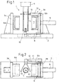
- the blow molding machine 1 shown in the figures comprises in a known manner a base frame 2, two closing plates 3a, 3b and an extrusion head 4, to which extruders (not shown) (one or more) are connected.
- the thermoplastic material which is plasticized via the extruders, not shown, emerges from an unspecified annular die of the extrusion head 4 as a tubular, warm-plastic preform - hereinafter referred to as preform hose 5.
- blow molding machine shown are mounted on the closing plates 3a, 3b respectively mold halves 6a, 6b and clamped together forming an article cavity 7.
- the blow molding machine 1 is designed as such a machine, in which the closing plates 3a, 3b and / or the mold halves 6a, 6b make a substantially horizontal movement in relation to the preforming tube 5 with respect to the setting plane.
- the preform tube 5, in turn, becomes substantially vertical with respect to the erection plane, i. extruded in the direction of gravity.
- mold halves is used here for the sake of simplicity.
- the term should be understood to mean that the tool does not necessarily have to consist of two halves complementary to one another. Rather, each mold half can be designed as a complex component with several moving parts or segments. The tool can also be designed, for example, a total of three parts.
- the closing plate 3a shown on the left in the drawing is designed as a stationary on the base frame 2 closing plate, whereas the arranged on the opposite side closing plate 3b is supported on both sides on a linear guide 8 on the base frame 2 and a hydraulic power drive 9 in the direction of the diametrically opposite Closing plate 3a is movable.
- On the closing plates 3a, 3b and / or on the mold halves 6a, 6b known per se locking means for locking the mold halves 6a, 6b or to increase the closing force on be provided the last part of the closing path. These locking devices are not shown here for the sake of simplicity.
- a hose spreading device or a hose closing device can also be provided. This is then moved in the same way simultaneously and in the same direction with the movable closing plate 3b and / or any relative movement of the preform tube 5 to the closing plates 3a, 3b.
- the movement sequences described here may be predetermined by an electronic control device not described in more detail or may be mechanically or fully coupled in whole or in part.
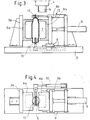
- preform tube 5 is removed by means of a handling device 11 on the extrusion head 4 after the preform tube 5 has been ejected to its full length, or has leaked.
- the handling device 11 is designed as a robot with a robot arm articulated about three spatial axes and a gripper 13. Like a synopsis of FIGS. 1 to 4 can be seen, the gripper 13 detects the hanging on the extrusion head 4 cut to length preform hose 5.
- the preform tube 5 is separated from the extrusion head 4. This can be done by tearing off by means of the gripper 13. In this case can be generated by wall thickness control of the preform tube 5 in the extrusion head 4, a thin point, which facilitates the tearing off.
- the preform tube 5 can be separated by means of a separating device, not shown, on the extrusion head 4.
- the preform tube 5 has already been extruded between the open mold halves 6a, 6b of the tool, alternatively it is also possible to extrude the preform tube 5 elsewhere and to place it by means of the gripper 13 between the opened mold halves 6a, 6b of the tool.
- the closing plate 3b shown on the right in the drawing moves in the direction of the oppositely arranged stationary closing plate 3a, by actuation of the power drive 9. It is now provided that the gripper 13 is moved in the same direction as the movable closing plate 3b in the direction of the stationary closing plate 3a with the hanging preform tube 5 and the immersed in the preform tube 10, in such a way that the preform tube 5 until the completion of the closing operation between the mold halves 6a, 6b and / or is centered between the closure plates 3a / 3b, with the result that the mold halves 6a, 6b come into contact with the preform tube 5 simultaneously. With respect to the preform hose, therefore, a symmetrical closing movement of the mold halves 6a, 6b is completed.
- the procedure described above has the advantage that an earlier one-sided mold contact of the preform tube 5 is reliably avoided.
- a non-symmetrical closing movement can be realized at least over parts of the closing path by means of the described blow molding machine.
- the preform tube 5 is widened within the article cavities 7 formed by the mold halves 6a, 6b, so that the preform tube 5 assumes the shape of the finished article, which corresponds to the inner contour of the article cavity 7.
- a squeezing of the preforming tube 5 is effected at least in regions on the circumference of the finished article, with the formation of a partially projecting edge (slug).
- the closing plates 3a, 3b are moved apart and the article is on the handling device 11 opposite side taken from the blow molding machine.
- a removal gripper may be provided, which is not shown in the figures.
- the design of the blow molding machine 1 without the usual spars has the advantage that both the handling device 11 and a removal gripper have free access to the space between the mold halves 6a, 6b.
- the holmenlose training the blow molding machine 1 also has the advantage that the installation and removal of the tools is easier.
- a removal gripper or another article removal device has to perform a partial movement in the direction of the closing axis of the closure plates 3a, 3b.
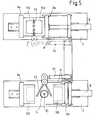
- FIG. 5 an arrangement of two blow molding machines 1 is shown in plan view, in which the handling of the preform tube 5 is performed by means of a common handling device 11.
- the cycles of the opening and closing movements of the closing plates 3a, 3b are chosen so that the handling device 11 can operate alternately one or the other blow molding machine.
Landscapes
- Engineering & Computer Science (AREA)
- Manufacturing & Machinery (AREA)
- Mechanical Engineering (AREA)
- Blow-Moulding Or Thermoforming Of Plastics Or The Like (AREA)
- Moulds For Moulding Plastics Or The Like (AREA)
Description
Die Erfindung betrifft eine Blasformmaschine zur Herstellung von Hohlkörpern aus thermoplastischem Kunststoff, mit einem vorzugsweise holmenlosen Grundrahmen, mit wenigstens zwei als Schließplatten ausgebildeten Formaufspannplatten, mit jeweils auf den Schließplatten angeordneten Formwerkzeugen, die geschlossen eine Artikelkavität bilden, wobei eine erste Schließplatte stationär und eine zweite Schließplatte beweglich angeordnet ist, wobei die Formwerkzeuge über die Bewegung der Schließplatten relativ zueinander von einer Offenstellung in eine geschlossene Stellung bringbar sind, und mit wenigstens einem Extrusionskopf zum Ausstoßen eines Vorformling aus plastifiziertem Kunststoff.The invention relates to a blow molding machine for producing hollow bodies made of thermoplastic material, with a preferably sparless base frame, with at least two mold plates designed as closing plates, each with arranged on the closing plates forming tools that form a closed article cavity, wherein a first closing plate stationary and a second closing plate is movably arranged, wherein the molds are brought about the movement of the closing plates relative to each other from an open position to a closed position, and with at least one extrusion head for ejecting a preform made of plasticized plastic.
Die Erfindung betrifft weiterhin ein Verfahren zum Extrusionsblasformen von Hohlkörpern aus thermoplastischem Kunststoff mit einer vorzugsweise holmenlosen Blasformmaschine mit wenigstens zwei Schließplatten und auf diesen angeordneten Formwerkzeugen, wobei eine erste Schließplatte stationär und eine zweite Schließplatte beweglich ausgebildet ist, wobei das Verfahren das Extrudieren wenigstens eines Vorformlings aus plastifiziertem Kunststoff umfasst, der Vorformling zwischen den geöffneten Formwerkzeugen angeordnet wird, die Formwerkzeuge um den Vorformling geschlossen werden und der Vorformling innerhalb einer von den Formwerkzeugen gebildeten Artikelkavität ausgeweitet wird.The invention further relates to a method for the extrusion blow molding of hollow bodies of thermoplastic material with a preferably Holmenlose blow molding machine with at least two closing plates and arranged thereon forming tools, a first closing plate stationary and a second closing plate is movable, the method comprises extruding at least one preform plasticized plastic, the preform is placed between the open dies, the dies are closed around the preform, and the preform is expanded within an article cavity formed by the dies.
Unter Ausstoßen eines Vorformlingsschlauchs aus einem Extrusionskopf ist im Sinne der Offenbarung sowohl die Diskontinuierliche als auch die Kontinuierliche Extrusion eines plastifizierten Kunststoffs aus einem hierfür vorgesehenen Extrusionskopf zu verstehen. Kontinuierliche Extrusion bedeutet in diesem Zusammenhang, dass die plastifizierte Masse kontinuierlich aus einer Ringspaltdüse des Extrusionskopfes austritt. Diskontinuierliche Extrusion bedeutet, dass das plastifizierte Material zunächst in einen Ringkolbenspeicher des Extrusionskopfs gefördert wird und mittels eines Ringkolbens vollständig innerhalb eines verhältnismäßig kurzen Zeitraums aus dem Extrusionskopf herausgedrückt wird.In the sense of the disclosure, ejecting a preform hose from an extrusion head is to be understood as meaning both the discontinuous and the continuous extrusion of a plasticized plastic from an extrusion head provided for this purpose. Continuous extrusion in this context means that the plasticized mass emerges continuously from an annular die of the extrusion head. Batch extrusion means that the plasticized material is first conveyed into an annular piston accumulator of the extrusion head and is completely expelled from the extrusion head within a relatively short period of time by means of an annular piston.
Formwerkzeuge oder Formhälften im Sinne der Erfindung bedeutet nicht zwangsläufig, dass das damit bezeichnete Werkzeug nur aus zwei zueinander komplementären Hälften besteht, die insgesamt die Artikelkavität bilden, vielmehr können die einzelnen Teile, die beispielsweise im Sinne von Formhälften eine Öffnungs- und Schließbewegung vollziehen, aus mehreren einzeln relativ zueinander bewegbaren bzw. verfahrbaren Elementen bestehen. Auch müssen die Formwerkzeuge keine vertikale Trennnaht aufweisen, vielmehr kann eine solche Trennnaht einen beliebigen Verlauf aufweisen. Artikelkavität im Sinne der Erfindung ist nicht zwangsläufig so zu verstehen, dass eine Kavität für einen Artikel vorgesehen ist, vielmehr kann das Werkzeug als sogenanntes Mehrkavitätenwerkzeug ausgeführt sein. Darüber hinaus können aber auch in an und für sich bekannter Art und Weise in einer Kavität mehrere Artikel hergestellt werden mittels eines oder mehrerer Vorformlinge.Forming tools or mold halves within the meaning of the invention does not necessarily mean that the tool thus designated consists only of two mutually complementary halves, which together form the article cavity, but the individual parts that perform an opening and closing movement, for example in the sense of mold halves from consist of several individually movable relative to each other or movable elements. Also, the molds need not have a vertical seam, but rather such a seam can have any course. Article cavity according to the invention is not necessarily to be understood that a cavity is provided for an article, but the tool can be designed as a so-called Mehrkavitätenwerkzeug. In addition, however, several articles can also be produced in one cavity in a manner known per se by means of one or more preforms.
Vorformlinge können sowohl schlauchförmige Vorformlinge als auch bahnförmige Vorformlinge sein. Letztere können beispielsweise durch Extrusion mittels einer Breitschlitzdüse erhalten worden sein oder durch Auftrennen eines zunächst schlauchförmigen extrudierten Vorformlings zu zwei oder mehreren bahnförmigen Elementen.Preforms can be both tubular preforms and sheet-like preforms. The latter may have been obtained, for example, by extrusion by means of a slot die, or by separating an initially tubular extruded preform into two or more sheet-like elements.
Eine Blasformmaschine der Eingangs genannten Art ist beispielsweise aus der
Wie aus der
Aus diesem Grund wird in der
Eine Blasformmaschine mit einer stationären Formhälfte und einer bewegbaren Formhälfte ist beispielsweise aus der
Ein so früher Formkontakt des Vorformlings ist jedoch nicht immer wünschenswert, da der Vorformling bei Berührung mit dem Werkzeug partiell abkühlt was unter Umständen beim Aufweiten innerhalb der geschlossenen Kavität zu einem unregelmäßigen Reckverhalten des Vorformlings führen kann.However, such an early mold contact of the preform is not always desirable because the preform partially cools upon contact with the tool, which under certain circumstances may result in an irregular stretching behavior of the preform during expansion within the closed cavity.
Bei einer vertikalen Trennnaht bzw. vertikalen Trennebene der Formwerkzeuge ist häufig eine symmetrische und synchrone Schließbewegung der Formwerkzeuge zueinander wünschenswert. Insbesondere in der Endphase der Schließbewegung ist ein symmetrisches Schließen der Formwerkzeuge wünschenswert, um eine einwandfreie Schweißnahtbildung am fertigen Artikel zu gewährleisten. Aus diesem Grund ist das in der
Die Aufgabe wird gelöst durch eine Blasformmaschine mit den Merkmalen des Anspruchs 1 sowie durch ein Verfahren zum Extrusionsblasformen von Hohlkörpern aus thermoplastischem Kunststoff nach Anspruch 9.The object is achieved by a blow molding machine with the features of
Ein Gesichtspunkt der Erfindung betrifft eine Blasformmaschine zur Herstellung von Hohlkörpern aus thermoplastischem Kunststoff gemäß Anspruch 1. Die Erfindung kann im Wesentlichen dahingehend zusammengefasst werden, dass Mittel vorgesehen sind, um dem Vorformlingsschlauch eine der Schließbewegung der Formwerkzeuge überlagerte Bewegung aufzugeben, sodass trotz Anordnung einer stationären Schließplatte und einer hierzu beweglichen Schließplatte ggf. eine synchrone Schließbewegung der Schließplatten bzw. der Formwerkzeuge bezüglich des Vorformlingsschlauchs erzielt werden kann. Nicht immer ist eine solche Synchronität der Schließbewegung über den gesamten Zyklus wünschenswert. Dies hängt unter anderem auch davon ab, ob beispielsweise das Werkzeug eine vertikale oder schiefe Trennebene aufweist. Die Begriffe vertikal oder schief beziehen sich hier auf die Längsachse des entweder am Extrusionskopf oder an einer Handhabungseinrichtung hängenden Vorformlingsschlauchs. Ist die Werkzeugtrennebene in Form einer schiefen Ebene ausgestaltet, kann es unter Umständen vorteilhaft sein, wenn die Schließbewegung nur über eine Teilstrecke synchronisiert ist.One aspect of the invention relates to a blow molding machine for the production of hollow bodies made of thermoplastic material according to
Unter einer synchronen Schließbewegung im Sinne der Erfindung ist eine gleichsinnige Annäherung der Formhälften an den Vorformling mit gleicher Geschwindigkeit zu verstehen. Hierfür ist lediglich die Relativbewegung zwischen den Formwerkzeugen und/oder den Schließplatten und der Ebene, in der die Längsachse des Schlauchs verläuft, maßgeblich.Under a synchronous closing movement in the context of the invention is to be understood in the same direction approximation of the mold halves to the preform at the same speed. For this purpose, only the relative movement between the molds and / or the closing plates and the plane in which the longitudinal axis of the hose extends, decisive.
Bei einer Blasformmaschine gemäß der Erfindung ist vorgesehen, dass der Vorformling in Richtung und vorzugsweise synchron mit der Schließbewegung der zweiten Schließplatte über wenigstens eine Teilstrecke des Schließwegs bewegbar ist.In a blow molding machine according to the invention, provision is made for the preform to be movable in the direction and preferably synchronously with the closing movement of the second closing plate over at least one part of the closing path.
Dies kann erfindungsgemäß dadurch bewerkstelligt werden, dass der Grundrahmen in Bezug auf den Extrusionskopf gegensinnig zu der Schließbewegung der zweiten Schließplatte verfahrbar ist.This can be accomplished according to the invention in that the base frame in relation to the extrusion head in opposite directions to the closing movement of the second closing plate is movable.
Alternativ kann erfindungsgemäß der Extrusionskopf gleichsinnig zu der Schließbewegung der zweiten Schließplatte verfahrbar sein. Bei dieser und der zuvor beschriebenen Variante der Blasformmaschine kann der Schließvorgang des Werkzeugs bereits eingeleitet werden, während der Vorformling aus dem Extrusionskopf austritt. Eine nicht erfinderische alternative Ausführungsform der Blasformmaschine gemäß der Erfindung zeichnet sich durch eine Handhabungseinrichtung zur Bewegung des vollständig aus dem Extrusionskopf ausgestoßenen Vorformling aus. Die Handhabungseinrichtung kann auch dazu vorgesehen sein, den Vorformling von dem Extrusionskopf abzunehmen und zwischen die geöffneten Teile des Formwerkzeugs zu verbringen.Alternatively, according to the invention, the extrusion head can be moved in the same direction as the closing movement of the second closing plate. In this and the previously described variant of the blow molding machine, the closing operation of the tool can already be initiated while the preform exits the extrusion head. A non-inventive alternative embodiment of the blow molding machine according to the invention is characterized by a handling device for moving the preform completely ejected from the extrusion head. The handling device can also be provided to remove the preform from the extrusion head and to pass between the opened parts of the molding tool.
Die Handhabungseinrichtung kann mit einem Greifer ausgebildet sein.The handling device can be designed with a gripper.
Zweckmäßigerweise ist die Handhabungseinrichtung als ein um drei Raumachsen bewegbarer frei programmierbarer Roboterarm ausgebildet.Conveniently, the handling device is designed as a freely programmable robot arm movable about three spatial axes.
Eine Blasformmaschine, bei der der Maschinenrahmen eine der Schließbewegung überlagerte Bewegung vollzieht, kann beispielsweise eine Gleichlaufeinrichtung zur Synchronisation der Schließbewegung der Formwerkzeuge bezüglich einer Ebene, die durch die Längsachse des Vorformlings verläuft, aufweisen.For example, a blow molding machine in which the machine frame performs a movement superimposed on the closing movement may comprise synchronizing means for synchronizing the closing movement of the dies with respect to a plane passing through the longitudinal axis of the preform.
Als Gleichlaufeinrichtung kann beispielsweise eine mechanische Zwangskopplung des Maschinenrahmens mit einer der Schließplatten vorgesehen sein, sodass die Schließbewegung der bewegbaren Schließplatte über mechanische Hilfsmittel, beispielsweise über ein Getriebe auf den Maschinenraum übertragen wird.For example, a mechanical forced coupling of the machine frame with one of the closing plates may be provided as synchronizing device, so that the closing movement of the movable closing plate is transmitted to the machine room via mechanical aids, for example via a gear.
Die Offenbarung ist selbstverständlich so zu verstehen, dass die Synchronisation der Bewegungsabläufe grundsätzlich über eine elektronische Maschinensteuerung erfolgen kann, ohne das hierzu notwendigerweise eine mechanische Zwangskopplung vorgesehen sein müsste.Of course, the disclosure is to be understood as meaning that the synchronization of the movements basically takes place via an electronic machine control can take place without necessarily a mechanical forced coupling would have to be provided for this purpose.
Die erfindungsgemäße Blasformmaschine bietet den Vorzug, dass sie bedarfsweise ohne Holme auskommt und trotz nur einer bewegten Schließplatte, wodurch an bewegter Masse gespart wird, eine weitestgehend flexible Steuerung der Relativbewegung zwischen den Formwerkzeugen und dem Vorformling ermöglicht.The blow molding machine according to the invention has the advantage that it does not require any spars and, despite only one moving closing plate, which saves on moving mass, allows a largely flexible control of the relative movement between the molds and the preform.
Ein zweiter Gesichtspunkt der Erfindung betrifft ein Verfahren zum Extrusionsblasformen von Hohlkörpern aus thermoplastischem Kunststoff gemäß Anspruch 4. Zweckmäßigerweise ist vorgesehen, dass die Relativbewegung zwischen dem Vorformling und den Schließplatten und/oder den Formwerkzeugen so gesteuert wird, dass die Ebene, durch die die Längsachse des Vorformlings verläuft, zumindest während eines Teilzyklus der Schließbewegung zwischen den Schließplatten und/oder Formwerkzeugen zentriert ist.A second aspect of the invention relates to a method for extrusion blow molding of hollow bodies made of thermoplastic material according to claim 4. It is expediently provided that the relative movement between the preform and the closing plates and / or the forming tools is controlled so that the plane through which the longitudinal axis of the Preform extends, at least during a part cycle of the closing movement between the closing plates and / or molds is centered.
Bei einer Variante des Verfahrens wird der Vorformling während des Schließvorgangs in Richtung und vorzugsweise synchron mit der Schließbewegung der zweiten Schließplatte wenigstens über eine Teilstrecke der Schließbewegung mitbewegt.In a variant of the method, the preform is moved during the closing operation in the direction and preferably synchronously with the closing movement of the second closing plate at least over a part of the closing movement.
Alternativ kann die Schließplattenanordnung in Bezug auf einen Extrusionskopf gegensinnig zur Schließbewegung der Schließplatten verfahren werden.Alternatively, the closing plate arrangement can be moved in relation to an extrusion head in the opposite direction to the closing movement of the closing plates.
Eine weitere alternative Verfahrensweise sieht vor, dass der Extrusionskopf gleichsinnig zur Schließbewegung der Schließplatten verfahren wird.A further alternative procedure provides that the extrusion head is moved in the same direction as the closing movement of the closing plates.
Eine andere Verfahrensweise sieht vor, dass der Vorformlingsschlauch mittels einer Handhabungseinrichtung am Extrusionskopf abgenommen wird und von der Handhabungseinrichtung während des Schließvorgangs über wenigstens eine Teilstrecke der Bewegung der zweiten Schließplatte synchron mit dieser zwischen den Schließplatten mitbewegt wird.Another procedure provides that the preform hose is removed by means of a handling device on the extrusion head and is moved by the handling device during the closing operation over at least a portion of the movement of the second closing plate in synchronism with this between the closing plates.
Die Erfindung wird nachstehend anhand eines in den Zeichnungen dargestellten Beispiels erläutert.The invention will be explained below with reference to an example shown in the drawings.
Es zeigen:
Figur 1- einen Teilschnitt durch eine Blasformmaschine gemäß der Erfindung mit vollständig geöffneten Formwerkzeugen,
Figur 2- eine Draufsicht auf die Blasformmaschine in
Figur 1 - Figur 3
- einenTeilschnitt durch eine Blasformmaschine gemäß der Erfindung entsprechend der in
Figur 1 - Figur 4
- eine Draufsicht auf die Blasformmaschine in
Figur 3 und Figur 5- eine Draufsicht auf eine Anordnung zweier Blasformmaschinen gemäß der Erfindung, denen eine gemeinsame Handhabungseinrichtung zugeordnet ist.
- FIG. 1
- a partial section through a blow molding machine according to the invention with fully open molds,
- FIG. 2
- a plan view of the blow molding machine in
FIG. 1 . - FIG. 3
- a partial section through a blow molding machine according to the invention according to the in
FIG. 1 blow molding machine shown, but with closing or almost closed molds, - FIG. 4
- a plan view of the blow molding machine in
FIG. 3 and - FIG. 5
- a plan view of an arrangement of two blow molding machines according to the invention, which is associated with a common handling device.
Die in den Figuren dargestellte Blasformmaschine 1 umfasst in bekannter Art und Weise einen Grundrahmen 2, zwei Schließplatten 3a, 3b und einen Extrusionskopf 4, an den nicht dargestellte Extruder (einer oder mehrere) angeschlossen sind. Das über die nicht dargestellten Extruder plastifizierte thermoplastische Material tritt aus einer nicht bezeichneten Ringspaltdüse des Extrusionskopfs 4 als schlauchförmiger, warmplastischer Vorformling - nachstehend als Vorformlingsschlauch 5 bezeichnet - aus.The
Bei der in
Die Blasformmaschine 1 gemäß der Erfindung ist als eine solche Maschine ausgebildet, bei der die Schließplatten 3a, 3b und/oder die Formhälften 6a, 6b in Bezug auf die Aufstellebene eine im Wesentlichen horizontale Bewegung in Bezug auf den Vorformlingsschlauch 5 vollziehen. Der Vorformlingsschlauch 5 wiederum wird in Bezug auf die Aufstellebene im Wesentlichen vertikal, d.h. in Schwerkraftrichtung extrudiert.The
Wie eingangs bereits erwähnt, wird hier der Einfachheit halber der Begriff Formhälften verwendet, Der Begriff ist so zu verstehen, dass das Werkzeug nicht notwendigerweise aus zwei zueinander komplementären Hälften bestehen muss. Vielmehr kann jede Formhälfte als komplexes Bauteil mit mehreren beweglichen Teilen oder Segmenten ausgebildet sein. Das Werkzeug kann darüber hinaus beispielsweise auch insgesamt dreiteilig ausgebildet sein.As already mentioned, the term mold halves is used here for the sake of simplicity. The term should be understood to mean that the tool does not necessarily have to consist of two halves complementary to one another. Rather, each mold half can be designed as a complex component with several moving parts or segments. The tool can also be designed, for example, a total of three parts.
Die in der Zeichnung links dargestellte Schließplatte 3a ist als auf dem Grundrahmen 2 stationär angeordnete Schließplatte ausgebildet, wohingegen die auf der gegenüberliegenden Seite angeordnete Schließplatte 3b beidseitig auf einer Linearführung 8 am Grundrahmen 2 abgestützt ist und über einen hydraulischen Kraftantrieb 9 in Richtung auf die diametral gegenüberliegende Schließplatte 3a bewegbar ist. An den Schließplatten 3a,3b und/oder an den Formhälften 6a, 6b können an und für sich bekannte Verriegelungseinrichtungen zum Zuhalten der Formhälften 6a, 6b oder zur Verstärkung der Schließkraft über den letzten Teil des Schließweges vorgesehen sein. Diese Verriegelungseinrichtungen sind der Einfachheit halber hier nicht dargestellt. Mit 10 ist ein Blasdorn bezeichnet, der gleichzeitig und gleichsinnig mit der verfahrbaren Schließplatte 3b und/oder einer etwaigen Relativbewegung des Vorformlingsschlauchs 5 zu den Schließplatten 3a, 3b verfahrbar ist. In dem Bereich der Blasformmaschine 1 kann auch eine Schlauchspreizvorrichtung oder auch eine Schlauchschließvorrichtung vorgesehen sein. Dies wird dann in gleicher Weise gleichzeitig und gleichsinnig mit der verfahrbaren Schließplatte 3b und/oder einer etwaigen Relativbewegung des Vorformlingsschlauchs 5 zu den Schließplatten 3a, 3b verfahren.The
Die hier beschriebenen Bewegungsabläufe können von einer nicht näher beschriebenen elektronischen Steuereinrichtung vorgegeben sein oder ganz oder teilweise mechanisch gekoppelt sein.The movement sequences described here may be predetermined by an electronic control device not described in more detail or may be mechanically or fully coupled in whole or in part.
Bei den anhand der beigefügten Zeichnungen erläuterten Ausführungsbeispielen wird der Vorformlingsschlauch 5 mittels einer Handhabungseinrichtung 11 am Extrusionskopf 4 abgenommen, nachdem der Vorformlingsschlauch 5 auf seine volle Länge ausgestoßen wurde, bzw. ausgetreten ist.In the illustrated with reference to the accompanying drawings embodiments of the
Die Handhabungseinrichtung 11 ist als Roboter mit einem um drei Raumachsen artikulierbaren Roboterarm und einem Greifer 13 ausgebildet. Wie einer Zusammenschau der
Ist der Vorformlingsschlauch 5 zwischen den Formhälften 6a, 6b des Werkzeugs angeordnet, verfährt die in der Zeichnung rechts dargestellte Schließplatte 3b in Richtung auf die gegenüberliegend angeordnete stationäre Schließplatte 3a, und zwar durch Betätigung des Kraftantriebs 9. Es wird nun vorgesehen, dass der Greifer 13 mit dem daran hängenden Vorformlingsschlauch 5 sowie dem in den Vorformlingsschlauch eingetauchten Blasdorn 10 gleichsinnig wie die verfahrbare Schließplatte 3b in Richtung auf die stationäre Schließplatte 3a mitbewegt wird, und zwar derart, dass der Vorformlingsschlauch 5 bis zur Vollendung des Schließvorgangs zwischen den Formhälften 6a, 6b und/oder zwischen den Schließplatten 3a/3b zentriert ist, mit dem Ergebnis, dass die Formhälften 6a, 6b gleichzeitig mit dem Vorformlingsschlauch 5 in Kontakt gelangen. In Bezug auf den Vorformlingsschlauch wird also eine symmetrische Schließbewegung der Formhälften 6a, 6b vollzogen.If the preforming
Die zuvor beschriebene Verfahrensweise hat den Vorzug, dass ein früher einseitiger Formkontakt des Vorformlingsschlauchs 5 zuverlässig vermieden wird.The procedure described above has the advantage that an earlier one-sided mold contact of the
Wie eingangs bereits erwähnt wurde, kann mittels der beschriebenen Blasformmaschine auch eine nicht symmetrische Schließbewegung zumindest über Teile des Schließweges realisiert werden.As already mentioned, a non-symmetrical closing movement can be realized at least over parts of the closing path by means of the described blow molding machine.
In einem weiteren nicht dargestellten Verfahrensschritt wird der Vorformlingsschlauch 5 innerhalb der von den Formhälften 6a, 6b gebildeten Artikelkavitäten 7 aufgeweitet, sodass der Vorformlingsschlauch 5 die Gestalt des fertigen Artikels annimmt, die der Innenkontur der Artikelkavität 7 entspricht. Dabei wird unter Krafteinwirkung zumindest bereichsweise am Umfang des fertigen Artikels eine Abquetschung des Vorformlingsschlauchs 5 bewirkt, und zwar unter Bildung eines teilweise vorstehenden Randes (Butzen).In a further process step, not shown, the
Anschließend werden die Schließplatten 3a, 3b auseinandergefahren und der Artikel wird auf der der Handhabungseinrichtung 11 gegenüberliegenden Seite der Blasformmaschine entnommen. Hierzu kann beispielsweise ein Entnahmegreifer vorgesehen sein, der in den Figuren nicht dargestellt ist.Subsequently, the
Die Ausbildung der Blasformmaschine 1 ohne die sonst üblichen Holme hat den Vorzug, dass sowohl die Handhabungseinrichtung 11 als auch ein Entnahmegreifer freien Zugang zu dem Freiraum zwischen den Formhälften 6a, 6b haben.The design of the
Die holmenlose Ausbildung der Blasformmaschine 1 hat darüber hinaus den Vorzug, das der Ein- und Ausbau der Werkzeuge erleichtert ist.The holmenlose training the
Es ist für den Fachmann einleuchtend, dass je nach Tiefe der Formhälften 6a, 6b bzw. der Teilkavitäten der Formhälften 6a, 6b ein Entnahmegreifer oder eine andere Vorrichtung zur Artikelentnahme eine Teilbewegung in Richtung der Schließachse der Schließplatten 3a, 3b vollziehen muss.It is obvious to a person skilled in the art that, depending on the depth of the
In
- 11
- Blasformmaschineblow molding machine
- 22
- Grundrahmenbase frame
- 3a, 3b3a, 3b
- Schließplattenstrikers
- 44
- Extrusionskopfextrusion head
- 55
- VorformlingsschlauchPreform tube
- 6a, 6b6a, 6b
- Formhälftenmold halves
- 77
- Artikelkavitätarticle cavity
- 88th
- Linearführunglinear guide
- 99
- Kraftantriebpower drive
- 1010
- Blasdornmandrel
- 1111
- Handhabungseinrichtunghandling device
- 1212
- Roboterarmrobot arm
- 1313
- Greifergrab
Claims (5)
- Blow moulding machine (1) for producing hollow bodies from thermoplastic material, comprising a base frame (2) without tie bars that has at least two mould platens formed as closing plates (3a, 3b), with moulds (6a, 6b) that in the closed state form an article cavity (7) respectively arranged on the closing plates (3a, 3b), wherein a first closing plate (3a) is arranged in a stationary manner and a second closing plate (3b) is arranged in a movable manner, wherein the moulds can be brought from an open position into a closed position by way of the movement of the closing plates (3a, 3b) in relation to one another, and comprising at least one extrusion head for providing a preform (5) of plasticated material, comprising means for the relative movement of the fully or partially extruded preform (5) with respect to the closing movement of the moulds (6a, 6b) in the axis of the closing movement, wherein the relative movement of the preform (5) is performed at the same time as the movement of the moulds (6a, 6b) and/or closing plates (3a, 3b), characterized in that the base frame (2) is movable in the opposite direction to the closing movement of the second closing plate (3b) with respect to the extrusion head (4) or in that the extruder and/or the extrusion head (4) is movable in the same direction as the closing movement of the second closing plate (3b).
- Blow moulding machine (1) according to Claim 1, characterized in that the preform (5) is movable in the direction of and preferably synchronously with the closing movement of the closing plates (3a, 3b) over at least a section of the closing path.
- Blow moulding machine (1) according to Claim 1, characterized by a synchronizing device for synchronization of the closing movement of the moulds (6a, 6b) with respect to a plane that extends through the longitudinal axis of the preform (5).
- Method for the extrusion blow moulding of hollow bodies from thermoplastic material with a blow moulding machine without tie bars, comprising at least two closing plates and moulds arranged on them, wherein a first closing plate is formed in a stationary manner and a second closing plate is formed in a movable manner, wherein the method comprises the extrusion of at least one preform of plasticated material, the preform is arranged between the opened moulds, the moulds are closed around the preform and the preform is expanded within an article cavity formed by the moulds, wherein a relative movement performed at the same time as the closing movement is imparted to the preform during the closing operation of the closing plates in the axis of the closing movement over at least a section of the closing path, characterized in that the closing plate arrangement is moved in the opposite direction to the closing movement of the second closing plate with respect to an extruder and/or extrusion head or in that the extruder and/or the extrusion head is moved in the same direction as the closing movement of the second closing plate.
- Method according to Claim 4, characterized in that the relative movement between the preform and the closing plates and/or the moulds is controlled such that the plane through which the longitudinal axis of the preform passes is centred, at least during part of the cycle of the closing movement between the closing plates and/or moulds.
Applications Claiming Priority (1)
| Application Number | Priority Date | Filing Date | Title |
|---|---|---|---|
| DE102007011000.8A DE102007011000B4 (en) | 2007-03-05 | 2007-03-05 | Blow molding machine and process for the extrusion blow molding of hollow bodies |
Publications (3)
| Publication Number | Publication Date |
|---|---|
| EP1967351A2 EP1967351A2 (en) | 2008-09-10 |
| EP1967351A3 EP1967351A3 (en) | 2015-01-21 |
| EP1967351B1 true EP1967351B1 (en) | 2018-06-13 |
Family
ID=39494529
Family Applications (1)
| Application Number | Title | Priority Date | Filing Date |
|---|---|---|---|
| EP08003627.0A Not-in-force EP1967351B1 (en) | 2007-03-05 | 2008-02-28 | Blow moulding machine and method for extrusion blow moulding of hollow bodies |
Country Status (2)
| Country | Link |
|---|---|
| EP (1) | EP1967351B1 (en) |
| DE (1) | DE102007011000B4 (en) |
Families Citing this family (2)
| Publication number | Priority date | Publication date | Assignee | Title |
|---|---|---|---|---|
| DE102007028882B4 (en) * | 2007-06-20 | 2015-04-23 | Kautex Textron Gmbh & Co. Kg | Extrusion blow molding machine and method for producing a hollow plastic body |
| CN114407334B (en) * | 2022-01-24 | 2023-01-31 | 广东乐善智能装备股份有限公司 | Processing technology of blow molding plastic packaging protection part and product thereof |
Family Cites Families (5)
| Publication number | Priority date | Publication date | Assignee | Title |
|---|---|---|---|---|
| GB789816A (en) * | 1954-12-22 | 1958-01-29 | Alfonso Amigo | Improvements in or relating to the manufacture of bottles and other hollow articles from plastic material |
| DE2148271A1 (en) * | 1971-09-28 | 1973-04-05 | Leifeld & Co | Two-stage plastics pressing machine - using blanks of extruded material in multiple impression fixed tools |
| DE4031697A1 (en) * | 1990-10-04 | 1992-04-09 | Leuna Werke Ag | High quality extruded tubular parison mfr. - has ring nozzle giving upward annular air flow over descending parison, allowing change in parison cross=section |
| US6176699B1 (en) * | 1999-04-28 | 2001-01-23 | Walbro Corporation | Parison handling device |
| DE19942600B4 (en) * | 1999-09-07 | 2008-03-06 | Sig Kautex Gmbh & Co. Kg | Use of a stationary and a movable platen in a Saugblasmaschine for producing hollow-body-shaped articles made of thermoplastic material |
-
2007
- 2007-03-05 DE DE102007011000.8A patent/DE102007011000B4/en not_active Expired - Fee Related
-
2008
- 2008-02-28 EP EP08003627.0A patent/EP1967351B1/en not_active Not-in-force
Non-Patent Citations (1)
| Title |
|---|
| None * |
Also Published As
| Publication number | Publication date |
|---|---|
| DE102007011000A1 (en) | 2008-09-11 |
| EP1967351A3 (en) | 2015-01-21 |
| DE102007011000B4 (en) | 2014-09-11 |
| EP1967351A2 (en) | 2008-09-10 |
Similar Documents
| Publication | Publication Date | Title |
|---|---|---|
| EP1864782B1 (en) | Method for manufacturing hollow bodies made of thermoplastic material having inserts on the inside and /or outside | |
| EP2026947B1 (en) | Method for producing hollow bodies from thermoplastic material by extrusion blow moulding with continuous die gap adjustment | |
| DE2161066B2 (en) | METHOD AND DEVICE FOR PRODUCING A HOLLOW BODY FROM THERMOPLASTIC PLASTIC | |
| EP2588294B1 (en) | Method for producing a plastics article and blow mould for carrying out the method | |
| EP0041073B1 (en) | Process and device for moulding molecular oriented thermoplastic hollow bodies | |
| DE2532413C2 (en) | Device for blow molding hollow bodies made of thermoplastic material | |
| EP1044784B1 (en) | Process and device for clamping blow moulds | |
| DE2307727B2 (en) | Method and device for forming a hollow body | |
| EP1884342A2 (en) | Device and method for blow moulding hollow thermoplastic bodies | |
| DE2703454C2 (en) | Method of making a bottle by blow molding | |
| EP2155468B1 (en) | Extrusion blow molding machine and method for the production of a hollow plastic body | |
| DE60208936T2 (en) | Blow molding and blow molding with mold trolley | |
| DE1038750B (en) | Method and device for the production of bottles or similar hollow bodies from organic thermoplastics | |
| EP1967351B1 (en) | Blow moulding machine and method for extrusion blow moulding of hollow bodies | |
| DE3429141C2 (en) | Process for producing a hollow body | |
| DE2132674A1 (en) | METHOD AND APPARATUS FOR MANUFACTURING HOLLOW BODIES WITH A NECK PART, IN PARTICULAR BOTTLES MADE FROM THERMOPLASTIC PLASTIC | |
| DE2256479A1 (en) | DEVICE FOR THE REMOVAL OF THE WASTE PART OF THE BLOW METHOD DURING THE MANUFACTURING OF A HOLLOW PLASTIC BODY WITH A HANDLE OR A HANDLE | |
| EP3986695B1 (en) | Molding tool and molding method for producing containers with undercuts | |
| DE4441037C2 (en) | Process and machine for blow molding a hollow body | |
| DE3723006A1 (en) | Process and device for producing thin-walled elastic vessels | |
| DE3828994C2 (en) | Tool and method for producing technical hollow bodies by extrusion blow molding | |
| EP2310181A2 (en) | Multi-part blow mould, method for producing a hollow body, hollow body and extrusion blow moulding machine | |
| DE1779897C3 (en) | Device for separating waste parts when producing hollow bodies, in particular bottles, cans and the like made of thermoplastic material. Excretion from; 1778404 | |
| DE1802916C (en) | Device for producing hollow bodies, in particular bottles, cans or the like, made of thermoplastic material | |
| DE1813618C3 (en) | Device for the production of hollow bodies, in particular bottles, cans or the like, made of thermoplastic material in the blow molding process |
Legal Events
| Date | Code | Title | Description |
|---|---|---|---|
| PUAI | Public reference made under article 153(3) epc to a published international application that has entered the european phase |
Free format text: ORIGINAL CODE: 0009012 |
|
| AK | Designated contracting states |
Kind code of ref document: A2 Designated state(s): AT BE BG CH CY CZ DE DK EE ES FI FR GB GR HR HU IE IS IT LI LT LU LV MC MT NL NO PL PT RO SE SI SK TR |
|
| AX | Request for extension of the european patent |
Extension state: AL BA MK RS |
|
| PUAL | Search report despatched |
Free format text: ORIGINAL CODE: 0009013 |
|
| AK | Designated contracting states |
Kind code of ref document: A3 Designated state(s): AT BE BG CH CY CZ DE DK EE ES FI FR GB GR HR HU IE IS IT LI LT LU LV MC MT NL NO PL PT RO SE SI SK TR |
|
| AX | Request for extension of the european patent |
Extension state: AL BA MK RS |
|
| RIC1 | Information provided on ipc code assigned before grant |
Ipc: B29C 49/42 20060101ALI20141218BHEP Ipc: B29C 49/04 20060101ALN20141218BHEP Ipc: B29C 49/56 20060101AFI20141218BHEP |
|
| 17P | Request for examination filed |
Effective date: 20150716 |
|
| RBV | Designated contracting states (corrected) |
Designated state(s): AT BE BG CH CY CZ DE DK EE ES FI FR GB GR HR HU IE IS IT LI LT LU LV MC MT NL NO PL PT RO SE SI SK TR |
|
| RBV | Designated contracting states (corrected) |
Designated state(s): AT BE BG CH CY CZ DE DK EE ES FI FR GB GR HR HU IE IS IT LI LT LU LV MC MT NL NO PL PT RO SE SI SK TR |
|
| AKX | Designation fees paid |
Designated state(s): AT BE BG CH CY CZ DE DK EE ES FI FR GB GR HR HU IE IS IT LI LT LU LV MC MT NL NO PL PT RO SE SI SK TR |
|
| AXX | Extension fees paid |
Extension state: AL Extension state: RS Extension state: BA Extension state: MK |
|
| GRAP | Despatch of communication of intention to grant a patent |
Free format text: ORIGINAL CODE: EPIDOSNIGR1 |
|
| STAA | Information on the status of an ep patent application or granted ep patent |
Free format text: STATUS: GRANT OF PATENT IS INTENDED |
|
| RIC1 | Information provided on ipc code assigned before grant |
Ipc: B29C 49/56 20060101AFI20171222BHEP Ipc: B29C 49/04 20060101ALN20171222BHEP Ipc: B29C 49/42 20060101ALI20171222BHEP |
|
| INTG | Intention to grant announced |
Effective date: 20180118 |
|
| GRAS | Grant fee paid |
Free format text: ORIGINAL CODE: EPIDOSNIGR3 |
|
| GRAA | (expected) grant |
Free format text: ORIGINAL CODE: 0009210 |
|
| STAA | Information on the status of an ep patent application or granted ep patent |
Free format text: STATUS: THE PATENT HAS BEEN GRANTED |
|
| AK | Designated contracting states |
Kind code of ref document: B1 Designated state(s): AT BE BG CH CY CZ DE DK EE ES FI FR GB GR HR HU IE IS IT LI LT LU LV MC MT NL NO PL PT RO SE SI SK TR |
|
| REG | Reference to a national code |
Ref country code: GB Ref legal event code: FG4D Free format text: NOT ENGLISH |
|
| REG | Reference to a national code |
Ref country code: CH Ref legal event code: EP Ref country code: AT Ref legal event code: REF Ref document number: 1008011 Country of ref document: AT Kind code of ref document: T Effective date: 20180615 |
|
| REG | Reference to a national code |
Ref country code: DE Ref legal event code: R096 Ref document number: 502008016120 Country of ref document: DE |
|
| REG | Reference to a national code |
Ref country code: IE Ref legal event code: FG4D Free format text: LANGUAGE OF EP DOCUMENT: GERMAN |
|
| REG | Reference to a national code |
Ref country code: NL Ref legal event code: MP Effective date: 20180613 |
|
| REG | Reference to a national code |
Ref country code: LT Ref legal event code: MG4D |
|
| PG25 | Lapsed in a contracting state [announced via postgrant information from national office to epo] |
Ref country code: ES Free format text: LAPSE BECAUSE OF FAILURE TO SUBMIT A TRANSLATION OF THE DESCRIPTION OR TO PAY THE FEE WITHIN THE PRESCRIBED TIME-LIMIT Effective date: 20180613 Ref country code: SE Free format text: LAPSE BECAUSE OF FAILURE TO SUBMIT A TRANSLATION OF THE DESCRIPTION OR TO PAY THE FEE WITHIN THE PRESCRIBED TIME-LIMIT Effective date: 20180613 Ref country code: LT Free format text: LAPSE BECAUSE OF FAILURE TO SUBMIT A TRANSLATION OF THE DESCRIPTION OR TO PAY THE FEE WITHIN THE PRESCRIBED TIME-LIMIT Effective date: 20180613 Ref country code: FI Free format text: LAPSE BECAUSE OF FAILURE TO SUBMIT A TRANSLATION OF THE DESCRIPTION OR TO PAY THE FEE WITHIN THE PRESCRIBED TIME-LIMIT Effective date: 20180613 Ref country code: CY Free format text: LAPSE BECAUSE OF FAILURE TO SUBMIT A TRANSLATION OF THE DESCRIPTION OR TO PAY THE FEE WITHIN THE PRESCRIBED TIME-LIMIT Effective date: 20180613 Ref country code: NO Free format text: LAPSE BECAUSE OF FAILURE TO SUBMIT A TRANSLATION OF THE DESCRIPTION OR TO PAY THE FEE WITHIN THE PRESCRIBED TIME-LIMIT Effective date: 20180913 Ref country code: BG Free format text: LAPSE BECAUSE OF FAILURE TO SUBMIT A TRANSLATION OF THE DESCRIPTION OR TO PAY THE FEE WITHIN THE PRESCRIBED TIME-LIMIT Effective date: 20180913 |
|
| PG25 | Lapsed in a contracting state [announced via postgrant information from national office to epo] |
Ref country code: GR Free format text: LAPSE BECAUSE OF FAILURE TO SUBMIT A TRANSLATION OF THE DESCRIPTION OR TO PAY THE FEE WITHIN THE PRESCRIBED TIME-LIMIT Effective date: 20180914 Ref country code: LV Free format text: LAPSE BECAUSE OF FAILURE TO SUBMIT A TRANSLATION OF THE DESCRIPTION OR TO PAY THE FEE WITHIN THE PRESCRIBED TIME-LIMIT Effective date: 20180613 Ref country code: HR Free format text: LAPSE BECAUSE OF FAILURE TO SUBMIT A TRANSLATION OF THE DESCRIPTION OR TO PAY THE FEE WITHIN THE PRESCRIBED TIME-LIMIT Effective date: 20180613 |
|
| PG25 | Lapsed in a contracting state [announced via postgrant information from national office to epo] |
Ref country code: NL Free format text: LAPSE BECAUSE OF FAILURE TO SUBMIT A TRANSLATION OF THE DESCRIPTION OR TO PAY THE FEE WITHIN THE PRESCRIBED TIME-LIMIT Effective date: 20180613 |
|
| PG25 | Lapsed in a contracting state [announced via postgrant information from national office to epo] |
Ref country code: SK Free format text: LAPSE BECAUSE OF FAILURE TO SUBMIT A TRANSLATION OF THE DESCRIPTION OR TO PAY THE FEE WITHIN THE PRESCRIBED TIME-LIMIT Effective date: 20180613 Ref country code: EE Free format text: LAPSE BECAUSE OF FAILURE TO SUBMIT A TRANSLATION OF THE DESCRIPTION OR TO PAY THE FEE WITHIN THE PRESCRIBED TIME-LIMIT Effective date: 20180613 Ref country code: IS Free format text: LAPSE BECAUSE OF FAILURE TO SUBMIT A TRANSLATION OF THE DESCRIPTION OR TO PAY THE FEE WITHIN THE PRESCRIBED TIME-LIMIT Effective date: 20181013 Ref country code: PL Free format text: LAPSE BECAUSE OF FAILURE TO SUBMIT A TRANSLATION OF THE DESCRIPTION OR TO PAY THE FEE WITHIN THE PRESCRIBED TIME-LIMIT Effective date: 20180613 Ref country code: CZ Free format text: LAPSE BECAUSE OF FAILURE TO SUBMIT A TRANSLATION OF THE DESCRIPTION OR TO PAY THE FEE WITHIN THE PRESCRIBED TIME-LIMIT Effective date: 20180613 Ref country code: RO Free format text: LAPSE BECAUSE OF FAILURE TO SUBMIT A TRANSLATION OF THE DESCRIPTION OR TO PAY THE FEE WITHIN THE PRESCRIBED TIME-LIMIT Effective date: 20180613 |
|
| REG | Reference to a national code |
Ref country code: DE Ref legal event code: R097 Ref document number: 502008016120 Country of ref document: DE |
|
| PLBE | No opposition filed within time limit |
Free format text: ORIGINAL CODE: 0009261 |
|
| STAA | Information on the status of an ep patent application or granted ep patent |
Free format text: STATUS: NO OPPOSITION FILED WITHIN TIME LIMIT |
|
| 26N | No opposition filed |
Effective date: 20190314 |
|
| PG25 | Lapsed in a contracting state [announced via postgrant information from national office to epo] |
Ref country code: DK Free format text: LAPSE BECAUSE OF FAILURE TO SUBMIT A TRANSLATION OF THE DESCRIPTION OR TO PAY THE FEE WITHIN THE PRESCRIBED TIME-LIMIT Effective date: 20180613 Ref country code: SI Free format text: LAPSE BECAUSE OF FAILURE TO SUBMIT A TRANSLATION OF THE DESCRIPTION OR TO PAY THE FEE WITHIN THE PRESCRIBED TIME-LIMIT Effective date: 20180613 |
|
| REG | Reference to a national code |
Ref country code: CH Ref legal event code: PL |
|
| GBPC | Gb: european patent ceased through non-payment of renewal fee |
Effective date: 20190228 |
|
| PG25 | Lapsed in a contracting state [announced via postgrant information from national office to epo] |
Ref country code: LU Free format text: LAPSE BECAUSE OF NON-PAYMENT OF DUE FEES Effective date: 20190228 Ref country code: MC Free format text: LAPSE BECAUSE OF FAILURE TO SUBMIT A TRANSLATION OF THE DESCRIPTION OR TO PAY THE FEE WITHIN THE PRESCRIBED TIME-LIMIT Effective date: 20180613 |
|
| REG | Reference to a national code |
Ref country code: BE Ref legal event code: MM Effective date: 20190228 |
|
| REG | Reference to a national code |
Ref country code: IE Ref legal event code: MM4A |
|
| PG25 | Lapsed in a contracting state [announced via postgrant information from national office to epo] |
Ref country code: LI Free format text: LAPSE BECAUSE OF NON-PAYMENT OF DUE FEES Effective date: 20190228 Ref country code: CH Free format text: LAPSE BECAUSE OF NON-PAYMENT OF DUE FEES Effective date: 20190228 |
|
| PG25 | Lapsed in a contracting state [announced via postgrant information from national office to epo] |
Ref country code: IE Free format text: LAPSE BECAUSE OF NON-PAYMENT OF DUE FEES Effective date: 20190228 Ref country code: GB Free format text: LAPSE BECAUSE OF NON-PAYMENT OF DUE FEES Effective date: 20190228 |
|
| PG25 | Lapsed in a contracting state [announced via postgrant information from national office to epo] |
Ref country code: FR Free format text: LAPSE BECAUSE OF NON-PAYMENT OF DUE FEES Effective date: 20190228 Ref country code: BE Free format text: LAPSE BECAUSE OF NON-PAYMENT OF DUE FEES Effective date: 20190228 |
|
| PG25 | Lapsed in a contracting state [announced via postgrant information from national office to epo] |
Ref country code: TR Free format text: LAPSE BECAUSE OF FAILURE TO SUBMIT A TRANSLATION OF THE DESCRIPTION OR TO PAY THE FEE WITHIN THE PRESCRIBED TIME-LIMIT Effective date: 20180613 |
|
| PG25 | Lapsed in a contracting state [announced via postgrant information from national office to epo] |
Ref country code: PT Free format text: LAPSE BECAUSE OF FAILURE TO SUBMIT A TRANSLATION OF THE DESCRIPTION OR TO PAY THE FEE WITHIN THE PRESCRIBED TIME-LIMIT Effective date: 20181015 Ref country code: MT Free format text: LAPSE BECAUSE OF FAILURE TO SUBMIT A TRANSLATION OF THE DESCRIPTION OR TO PAY THE FEE WITHIN THE PRESCRIBED TIME-LIMIT Effective date: 20180613 |
|
| PG25 | Lapsed in a contracting state [announced via postgrant information from national office to epo] |
Ref country code: HU Free format text: LAPSE BECAUSE OF FAILURE TO SUBMIT A TRANSLATION OF THE DESCRIPTION OR TO PAY THE FEE WITHIN THE PRESCRIBED TIME-LIMIT; INVALID AB INITIO Effective date: 20080228 |
|
| PGFP | Annual fee paid to national office [announced via postgrant information from national office to epo] |
Ref country code: AT Payment date: 20240327 Year of fee payment: 17 |
|
| PGFP | Annual fee paid to national office [announced via postgrant information from national office to epo] |
Ref country code: DE Payment date: 20240327 Year of fee payment: 17 |
|
| REG | Reference to a national code |
Ref country code: DE Ref legal event code: R082 Ref document number: 502008016120 Country of ref document: DE Representative=s name: ERNICKE PATENT- UND RECHTSANWAELTE PARTMBB, DE Ref country code: DE Ref legal event code: R081 Ref document number: 502008016120 Country of ref document: DE Owner name: KAUTEX MASCHINENBAU SYSTEM GMBH, DE Free format text: FORMER OWNER: KAUTEX MASCHINENBAU GMBH, 53229 BONN, DE |
|
| PGFP | Annual fee paid to national office [announced via postgrant information from national office to epo] |
Ref country code: IT Payment date: 20240328 Year of fee payment: 17 |
|
| REG | Reference to a national code |
Ref country code: AT Ref legal event code: PC Ref document number: 1008011 Country of ref document: AT Kind code of ref document: T Owner name: KAUTEX MASCHINENBAU SYSTEM GMBH, DE Effective date: 20241014 |
|
| REG | Reference to a national code |
Ref country code: DE Ref legal event code: R119 Ref document number: 502008016120 Country of ref document: DE |
|
| REG | Reference to a national code |
Ref country code: AT Ref legal event code: MM01 Ref document number: 1008011 Country of ref document: AT Kind code of ref document: T Effective date: 20250228 |
|
| PG25 | Lapsed in a contracting state [announced via postgrant information from national office to epo] |
Ref country code: AT Free format text: LAPSE BECAUSE OF NON-PAYMENT OF DUE FEES Effective date: 20250228 |
|
| PG25 | Lapsed in a contracting state [announced via postgrant information from national office to epo] |
Ref country code: DE Free format text: LAPSE BECAUSE OF NON-PAYMENT OF DUE FEES Effective date: 20250902 |
|
| PG25 | Lapsed in a contracting state [announced via postgrant information from national office to epo] |
Ref country code: IT Free format text: LAPSE BECAUSE OF NON-PAYMENT OF DUE FEES Effective date: 20250228 |