EP1967010B1 - image demosaicing method - Google Patents
image demosaicing method Download PDFInfo
- Publication number
- EP1967010B1 EP1967010B1 EP07716996.9A EP07716996A EP1967010B1 EP 1967010 B1 EP1967010 B1 EP 1967010B1 EP 07716996 A EP07716996 A EP 07716996A EP 1967010 B1 EP1967010 B1 EP 1967010B1
- Authority
- EP
- European Patent Office
- Prior art keywords
- pixel
- color
- image
- colors
- value
- Prior art date
- Legal status (The legal status is an assumption and is not a legal conclusion. Google has not performed a legal analysis and makes no representation as to the accuracy of the status listed.)
- Not-in-force
Links
Images

Classifications
-
- H—ELECTRICITY
- H04—ELECTRIC COMMUNICATION TECHNIQUE
- H04N—PICTORIAL COMMUNICATION, e.g. TELEVISION
- H04N9/00—Details of colour television systems
- H04N9/64—Circuits for processing colour signals
- H04N9/646—Circuits for processing colour signals for image enhancement, e.g. vertical detail restoration, cross-colour elimination, contour correction, chrominance trapping filters
-
- H—ELECTRICITY
- H04—ELECTRIC COMMUNICATION TECHNIQUE
- H04N—PICTORIAL COMMUNICATION, e.g. TELEVISION
- H04N1/00—Scanning, transmission or reproduction of documents or the like, e.g. facsimile transmission; Details thereof
- H04N1/46—Colour picture communication systems
- H04N1/56—Processing of colour picture signals
- H04N1/58—Edge or detail enhancement; Noise or error suppression, e.g. colour misregistration correction
-
- H—ELECTRICITY
- H04—ELECTRIC COMMUNICATION TECHNIQUE
- H04N—PICTORIAL COMMUNICATION, e.g. TELEVISION
- H04N23/00—Cameras or camera modules comprising electronic image sensors; Control thereof
- H04N23/80—Camera processing pipelines; Components thereof
- H04N23/84—Camera processing pipelines; Components thereof for processing colour signals
- H04N23/843—Demosaicing, e.g. interpolating colour pixel values
-
- H—ELECTRICITY
- H04—ELECTRIC COMMUNICATION TECHNIQUE
- H04N—PICTORIAL COMMUNICATION, e.g. TELEVISION
- H04N25/00—Circuitry of solid-state image sensors [SSIS]; Control thereof
- H04N25/10—Circuitry of solid-state image sensors [SSIS]; Control thereof for transforming different wavelengths into image signals
- H04N25/11—Arrangement of colour filter arrays [CFA]; Filter mosaics
- H04N25/13—Arrangement of colour filter arrays [CFA]; Filter mosaics characterised by the spectral characteristics of the filter elements
- H04N25/134—Arrangement of colour filter arrays [CFA]; Filter mosaics characterised by the spectral characteristics of the filter elements based on three different wavelength filter elements
Definitions
- Digital still cameras continue to increase in popularity and quality as the cost of such cameras continues to decline.
- Most digital still cameras use a single image sensor to capture color information for each pixel in a color image.
- the image sensor which is typically a charge-coupled device (CCD) or a complementary metal oxide semiconductor (CMOS), is part of a sensor array that together represent the pixels of a color image.
- CCD charge-coupled device
- CMOS complementary metal oxide semiconductor
- the image sensor can only generate information about a single color at a given pixel.
- a color image is represented by combining three separate monochromatic images.
- RGB red, blue and green
- a technique must be used to estimate or interpolate the missing colors from surrounding pixels in the image. This class of estimation and interpolation techniques is called "demosaicing".
- the "demosaicing” term is derived from the fact that a color filter array (CFA) is used in front of the image sensors, with the CFA being arranged in a mosaic pattern.
- This mosaic pattern has only one color value for each of the pixels in the image.
- the mosaic pattern In order to obtain the full-color image, the mosaic pattern must be "demosalced".
- demosaicing is the technique of interpolating back the image captured with a mosaic-pattern CFA, so that a full RGB value can be associated with every pixel.
- a single-sensor digital camera captures the image using an image sensor array that is preceded in the optical path by a CFA.
- a highly popular and common mosaic CFA is called the Bayer mosaic pattern. For each 2x2 set of pixels, two diagonally opposed pixels have green filters, and the other two pixels have red and blue filters. Since the color green (G) carries most of the luminance information for humans, its sampling rate is twice that of the color red (R) and the color blue (B).
- demosaicing techniques there are many types of demosaicing techniques currently available, such as bilinear interpolation, median filtering, vector CFA, gradient-based, and statistical modeling.
- each of these current demosaicing techniques produces visual and quantitatively measurable artifacts.
- artifacts include aliasing or "zippering” artifacts, where every other pixel along an edge alternates between being considered on or off the edge, and color fringing, where yellows, purples, and cyans appear along or on sharp edges.
- Lukac R et al "A robust, cost-effective post-processor for enhancing demosaicked camera images" relates to an efficient post processing/enhancement solution capable of reducing visual artifacts introduced during an image demosaicing process.
- Edge sensing weights and the original color filter array data are used to detect structural elements in the captured image, and correct color components generated by the demosaicing process using adaptive, spectral model based enhancement operations.
- US 4 724 395 relates to technique for sensing sample colored image data and thereafter interpolating the sampled colored image data to provide image data in each color sample or each point or pixel at which the subject is sensed from which an image of the subject may be constructing having reduced color artifacts and fringing while reducing a blurring to the image that would otherwise be required to correct for such artifacts and fringing.
- Yung-Yu Chuang et al "A bayesian approach to digital matting ", relates to a Bayesian framework for solving the matting problem, i.e. extracting a foreground element from a background image by estimating an opacity for each pixel of the foreground element.
- the Bayesian two-color image demosaicing method and system disclosed herein includes processing a digital color image to demosaic the image in such a way as to reduce image artifacts.
- the Bayesian two-color image demosaicing method and system employs an image model that models colors across an edge as a linear combination of the colors on each side. This decreases the possibility of inducing color fringing.
- the statistical model used by the Bayesian two-color image demosaicing method and system Is not grid-based, thus easily allowing for extensions to both multi-image demosaicing for video processing and non-iterative super-resolution output sampling. By constraining the output image to a linear model, visible noise in smooth areas also is reduced while preserving sharp edges.
- the Bayesian two-color image demosaicing method and system is an improvement on and an enhancement of existing demosaicing techniques.
- the method and system performs a preliminary demosaicing pass on an image to assign each pixel in the image a fully specified RGB triple color value.
- the results of this preliminary pass then are improved by the Bayesian two-color image demosaicing method and system.
- the general idea is that within a small window or processing region (such as a 5x5 pixel "patch") that is centered on a pixel being processed, an assumption is made that there only exists two colors within that processing region. Assuming only two colors results in the virtual elimination of random colors in the final result.
- the color of the pixel then is restricted to be a linear combination of those two colors. This alleviates spurious colors that cause the color artifacts.
- Bayesian two-color image demosaicing method includes obtaining fully-specified RGB triple color values for each pixel in an image and then using the RGB triples to determine a final color value for each pixel.
- the final color value is a combination of and only has contribution from two colors.
- the two colors are found by clustering the fully-specified RGB triples into two clusters, taking the mean of each cluster, and calling the means of each cluster the favored two colors.
- the favored two colors it must be determined how much contribution each color gives to the final color value. This is achieved by computing a fractional blended value for each pixel using samples in a processing region obtained from a Bayer color filter. Next, the maximum fractional blended value is found by finding the maximum probability of the fractional blended value given the set of samples. The final color value is computed from the maximum fractional blended value and the favored two colors.
- the Bayesian two-color image demosaicing method and system also can process multiple images to improve the demosaicing results.
- the multiple images first are registered with each other so that they are aligned.
- a reference image is selected, and the other images are reconstructed relative to the reference image.
- the processing is similar to the single image case, except that a technique is used to compensate for imperfect alignment of the images.
- the compensation technique uses a scaling factor to increase the variance of the Gaussian if the sum of the squared differences is large. This scaling factor varies based on the quality of the alignment algorithm.
- the Bayesian two-color image demosaicing method and system also can sample at a finer resolution, which is known as super resolution.
- super resolution the statistical clustering and local neighborhood sizes can be slightly shrunk to capture fine details.
- the system operates similarly as it did in the multi-image demosaicing case.
- FIGS. 1 and 2 are block diagrams illustrating two exemplary implementations of the Bayesian two-color image demosaicing method and system disclosed herein. It should be noted that FIGS. 1 and 2 are merely two of several ways in which the Bayesian two-color image demosaicing method and system may be implemented and used.
- the Bayesian two-color image demosaicer 200 resides on a digital camera system 210.
- the Bayesian two-color image demosaicer 200 provides enhancement to a color image (not shown) subsequent to a preliminary demosaicing pass made using a preliminary pass demosaicer 220.
- the Bayesian two-color image demosaicer 200 is part of the digital camera system 210 that includes an image sensor array 225.
- the array 225 is made up of a plurality of image sensors, where each image sensor is capable of determining a single color value.
- the image sensor array 225 includes a sensor substrate 230, a color filter array (CFA) 240, and lens 250. It should be noted that typically the lens 250 is disposed over the CFA 240, which in turn is disposed over the substrate 230, as indicated in FIGS. 1 and 2 by the dashed lines.
- the light from the image to be captured enters the digital camera system 210 (as shown by the arrows 255).
- the purpose of the lens 250 is to focus the incoming light 255 onto the image sensor array 225.
- Each sensor in the image sensor array 225 represents a pixel.
- the CFA 240 changes the color response of each pixel.
- the sensor substrate 230 captures the specific color incoming light (as dictated by the CFA 240) and generates an electrical signal. In this manner, the image sensor array 225 samples the incoming light 255 from an image with red, green and blue sensors arranged in the image sensor array 225.
- Each pixel in the image sensor array 225 is the output of a red, green or blue sensor.
- the sensor output is an electrical signal from each sensor that corresponds to a single color value for each pixel in the image sensor array 225.
- the output is raw, mosaic-patterned pixel data 260.
- color information for red, green and blue colors must be obtained at each pixel. This is achieved by demosaicing, or the interpolating the missing color values in the mosaic-patterned pixel data 260.
- the raw, mosaic-patterned pixel data 260 is sent to a first computing device 270 located onboard the digital camera system 210. Residing on the first computing device 270 are the preliminary pass demosaicer 220 and the Bayesian two-color image demosaicer 200.
- the preliminary pass demosaicer 220 is used to interpolate an estimate of the missing color values.
- the output of the preliminary pass demosaicer 220 is pixel data 280 containing full RGB color values for each pixel in the color image captured by the digital camera system 210.
- the Bayesian two-color image demosaicer 200 receives the pixel data 280 and processes this data 280 as described in detail below. After processing by the Bayesian two-color image demosaicer 200, an enhanced color digital image having reduced image artifacts 290 is obtained.
- the Bayesian two-color image demosaicer 200 resides on a second computing device 295 that is separate from the digital camera system 210.
- the raw mosaic-patterned pixel data 260 is sent from the digital camera system 210 to the second computing device 295.
- This pixel data 260 typically is sent to the second computing device 295 via an interface connection 297, which can be a USB interface, an IEEE 1394 interface, a Bluetooth ® interface, or any other interface suitable for carrying the raw pixel data 260 from the digital camera system 210 to the second computing device 295.
- the Bayesian two-color image demosaicer 200 uses the Bayesian two-color image demosaicing method to enhance the pixel data 260 and provides the enhanced color digital image having reduced image artifacts 290.
- FIG. 3 is a general flow diagram illustrating the general operation of the Bayesian two-color image demosaicer 200.
- the Bayesian two-color image demosaicing method inputs pixel color values for pixels in an image, processes each of the pixels, and outputs a processed image that has reduced image artifacts.
- the Bayesian two-color image demosaicing method begins by obtaining a fully-specified red (R), green (G), and blue (B) triple color.values for each pixel in a digital color image (box 300).
- Fully-specified RGB triple means that the red, green, and blue color values are available for the pixel.
- the Bayesian two-color image demosaicing method obtains these fully-specified RGB triple color values by performing a preliminary demosaicing pass on the digital color image. The Bayesian two-color image demosaicing method then enhances the results of the preliminary demosaicing pass.
- the Bayesian two-color image demosaicing method determines a final color value for each pixel in the digital color image (box 310).
- the final color value is a combination or blend of two colors, where the two colors are obtained by using at least some of the fully-specified RGB triple color values. In other words, even though there may be several colors contained in the fully-specified RGB triple color values, only a combination of two of those color values is used in determining a final color value for the pixel being processed.
- the output is a final color value that is found for each of the pixels in the digital color image (box 320).
- FIG. 4 is a detailed flow diagram illustrating the further details of the operation of the Bayesian two-color image demosaicing method shown in FIG. 3 .
- a preliminary demosaicing pass is performed to compute the fully-specified RGB triples for each pixel in the digital color image (box 400).
- the preliminary demosaicing pass uses a demosaicing technique to obtain an actual full color (RGB) value at each one of the pixels in a processing region centered at a pixel being processed.
- RGB full color
- the preliminary demosaicing pass is performed using a bilinear interpolation technique.
- other types of preliminary pass demosaicing techniques may be used, such as median filtering techniques, vector CFA techniques, gradient-based techniques, and statistical modeling techniques.
- a pixel is selected for processing and is defined as a processed pixel.
- a region around the processed pixel is defined as a processing region (box 410).
- the processing region typically is a 5x5 pixel patch, although other sizes are possible.
- the patch size is odd, such that the processed pixel is centered in the processing region.
- the processed pixel would be the center pixel of the 5x5 patch.
- Favored two colors then are computed for the processed pixel (box 420). This is achieved using the fully-specified RGB triples of each pixel in the processing region. As explained in detail below, the fully-specified RGB triples may contain several colors, but those colors are clustered into only two favored colors. A final color value for the processed pixel is computed using the favored two colors and the fully-specified RGB triples (box 430). The process of selecting a pixel, defining a processing region, computing the favored two colors, and computer a final color value all are repeated for the remainder of the pixels in the digital color image (box 440). The output of the Bayesian two-color image demosaicing method is an enhanced digital color image having reduced image artifacts (box 450).
- FIG. 5 is a flow diagram illustrating the favored two color computation process.
- FIG. 5 illustrates how the favored two colors are found from among the color values of pixels in the processing regions.
- the k-means clustering technique is a balance between accuracy and speed.
- the k-means clustering technique is well known by those having skill in the art, and will not be discussed in further detail.
- an expectation maximization (EM) technique or mean shift technique is used.
- an outlier can adversely affect the results.
- An outlier is a data point that is located far from the rest of the data. A statistical distribution expects data points to fall within a specific range, and those that do not are called outliers.
- the favored two color computation process includes an outlier rejection technique. The outlier rejection technique is used to minimize the influence of outliers on the favored two colors (box 510).
- the favored two colors then are computed by updating the clustering of the fully-specified RGB triples for each pixel in the processing region by using the outlier rejection results (box 520). The processing then is repeated for the remainder of the pixels in the digital color image (box 530). Favored two colors for each pixel then are obtained for each pixel in the image.
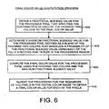
- FIG. 6 is a flow diagram illustrating details of the final color value computation process.
- the process begins by defining a fractional blended value for the processed pixel that specifies the contribution of each of the favored two colors to the final color value (box 600).
- the fractional blended value determines how much contribution the final color value of the pixel gets from each of the favored two colors.
- a maximum fractional blended value then is determined for the processed pixel (box 610).
- the maximum fractional blended value is defined as a blend or combination of the favored two colors that maximizes a probability of the fractional blended value using each of the fully-specified RGB triples in the processing region. This involves possibly looking for more than one set of colors, and then trying all those colors out to see which one gives the maximum value. For example, imagine trying three colors, J, K, and L, and trying all combinations of J, K, and L, and seeing which one gives the highest probability. Thus, out of all the colors, the favored two colors are the best two colors that explain the processed pixel.
- the "best" two colors means the two colors that maximizes the argument of the maximum (or "arg max") of equation (3) given below.
- the arg max is the value of a given argument for which the value of a given expression attains its maximum value.
- a final color value then is computed for the processed pixel using the favored two colors and the maximum fractional blended value (box 620). This final color value is set forth in equation (1) given below. The above processing is repeated for the remainder of the pixels in the digital color image in order to obtain a final color value for each of the pixels (box 630).
- a central assumption to processing by the Bayesian two-color image demosaicing method and system is that at most two representative colors exist within a local neighborhood.
- the final color value of every pixel within that neighborhood is either one of the representative colors or is a combination of both.
- the combination of the representative colors was a linear combination.
- the neighborhood surrounding each pixel was clustered into those two colors.
- the Bayer image provided only a single channel sample, leaving two unknown RGB triple color values and an unknown blending coefficient to specify the model.
- a weighted k-means technique was used in which the weight is the inverse Euclidean distance from each sample to the center of the kernel. Note that cluster sizes are not balanced, so a single pixel detail in an otherwise smooth area can be preserved. Also, clustering can be performed in other color spaces, such as L ⁇ or XYZ, but processing in these spaces made little difference in the accuracy of the clusters.
- the neighborhood size of samples to cluster is a function of how large color details appear in the source image.
- a two pixel radius around the kernel's center was found to work well. This supplied a sufficient number of samples from each of the Bayer color channels.
- the Bayesian two-color image demosaicing method and system also used an outlier rejection technique. Using the mean and variance of the clusters, samples that were outside of a single standard deviation of their closest cluster mean were rejected. The k-means technique then was repeated to obtain cleaner cluster means. This provided better reproduction where color values changed rapidly away from the kernel center.
- the major factor in the quality of clustering is the choice of a preliminary pass demosaicing technique used for the "bootstrapping" demosaicing to make clustering tractable.
- preliminary pass demosaicing techniques many types may be used (as listed above), there are qualities that improve performance.
- the first is preservation or accentuation of high frequency features. Techniques such as bilinear interpolation and median interpolation have a tendency to low-pass filter, which should be avoided. Alternately, algorithms that preserve high frequencies are prone to generate edge fringing and aliasing.
- HQLI high-quality linear interpolation
- Equation (1) is a blending equation, and computes the final color value, C, for the pixel x .
- the Bayer sensor gives a set of samples s i ⁇ S .
- the index of the RGB color channel specified by sample s i is denoted by t i
- a is the fractional blended value.
- s is an element of S for s i , where, for a 5x5 processing regions, i ranges from 1-25, such that there are 25 s i ' s.
- the s i ' s are only for a single channel (or color), and the color is specified by the t i ' s (either R, G, or B).
- equation (3) finds the arg max of a that maximizes the probability of ⁇ , given S , where S is the set of all the samples of colors that are in the processing regions (a 5x5 patch in this working example). It should be noted that S only contains samples that are actually sampled, and not obtained by demosaicing.
- equation (3) can be rearranged to yield: P ⁇
- S , J ⁇ , K ⁇ P S
- ⁇ , J ⁇ , K ⁇ . J , K , and a specify a predicted color, C * (1 - ⁇ ) J + ⁇ K for pixel x .
- Equation (6) computes the probability using a Gaussian.
- C * is the color computed given an ⁇ .
- the distribution between neighboring pixels is highly kurtotic, but for computational efficiency, a Gaussian distribution is assumed.
- the variance ⁇ i 2 is dependent on two factors: (1) the global per-channel image noise ⁇ N ; and, (2) the pixel distance between x and s i .
- the variance between s i and C ti increases as their distance in image space increases.
- equation (7) states that the variance increases linearly with distance from the center pixel (the processed pixel), or the pixel in the center of the processing region. In alternative embodiments, other monotonically increasing functions of distance may be used.
- the width of the Gaussian, or the variance, ⁇ 2 indicates how much influence a particular sample has on the final result. Another way to think about it is that it is the certainty of the sample. If there is uncertainty about a sample, its Gaussian will have a large width (or large variance, ⁇ 2 ). Conversely if there is certainty about a sample, its Gaussian will have a narrow width (or small variance, ⁇ 2 ).
- Equation (7) is a function that states that the variance increases with the distance from the processed (or center) pixel, around which the processing region is centered. In other words, pixels that are closer to the center pixel are more desirable and have a higher weight. And the more variance, the less influence that pixel or sample has on the final result. Thus, the variance should increase with the distance from the center pixel, by some function. Although a linear function in the form of equation (7) was used in this working example, other types of functions that state the variance in a similar way could also be used.
- equations (5)and (8) can be combined to yield: P s i
- ⁇ i 's When solving equations (10) and (11), the ⁇ i 's , and the ⁇ i 's need to be found, where the ⁇ 2 i ' s are the variances associated with each of the samples.
- the optimal fractional blended value, ⁇ * then is found, which is the optimal ⁇ value.
- ⁇ * then is used to compute the final color value.
- a slight penalty is imposed for an a value that is not 0 or 1. Consequently, in one embodiment, a has a value of 0, while in an alternative embodiment, a has a value of 1.
- equation (5) is evaluated with each of these three ⁇ 's to determine which a gives the highest answer.
- equation (10) the ⁇ i ' s and the ⁇ ⁇ i ' s then are computed.
- the ⁇ i 's are computed using equation (9).
- equation (9) computes the value of ⁇ .
- ⁇ is what the sample s i , says that ⁇ i should be.
- equation (10) a product of the ⁇ i 's is used. If a Gaussian is multiplied by a Gaussian, another Gaussian is obtained.
- the quantitative error of this approach can be further decreased by forcing the red, green, or blue at an output pixel to be the value originally captured by the sensor, while setting the other two channels to be consistent with ⁇ . Because ⁇ weights the central sample heavily, it is unlikely that these two values will be very different. Also, if the output sampling is done on a grid differing from the input grid, a source Bayer sample is not available at each pixel.
- the Bayesian two-color image demosaicing method and system can get samples from multiple images, as long as they are registered. Registering the images allows multiple images of a scene to be aligned together so they can be used. However, when the image are aligned they may not be oriented the same.
- the Bayesian two-color image demosaicing method and system selects a reference image and reconstructs the other images relative to the reference image. The processing region then becomes circular, and samples are taken within a certain radius of the processed (or center) pixel.
- the number of images used is 3, such that the processing time is fairly short and the quality is very good. In alternative embodiments, the number of images used may be more or less than three.
- ⁇ i ⁇ N ⁇ 1 + ⁇ ⁇ ⁇ d ⁇ 1 + ⁇ ⁇ ⁇ .
- ⁇ is the sum of squared differences.
- equation (13) is used.
- the only difference is the last term, (1+ ⁇ ).
- the ⁇ is a scaling factor. So the last term in equation (13), (1+ ⁇ ), states that the variance of the Gaussian is increased if the sum of the squared differences is large.
- T is how much the sum of the squared differences value is weighed. It is determined empirically. In one embodiment, T equals approximately 0.1. In alternative embodiments, othervalues of T may be used. However, it is important that T not be weighed too heavily. If T is too large, then information from other images may never be used. If T is too small, then information from other images may be used even if the images are not properly aligned. Thus, a balance must be found. The term T varies based on the quality of the alignment algorithm.
- any sampling grid can be used for the reconstruction, such as a sampling grid having a greater resolution than the original images.
- a continuous value of ⁇ can be generated anywhere in the image. Due to the alignment of samples from multiple images, the value of ⁇ may encode edges and sharpness between the pixels in the original grid. This can be exploited to handle super-resolution within the framework of the Bayesian two-color image demosaicing method and system.
- the statistical clustering and local neighborhood sizes can be slightly shrunk to capture fine details.
- the Bayesian two-color image demosaicing method and system operates similarly as it did in the multi-image demosaicing case.
- Bayesian two-color image demosaicer 200 The structure of the Bayesian two-color image demosaicer 200 now will be discussed. In order to more fully understand the structure of the Bayesian two-color image demosaicer 200, the details of an exemplary embodiment are presented. However, it should be noted that this exemplary embodiment is only one of several ways in which the Bayesian two-color image demosaicer 200 may be implemented and used.
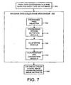
- FIG. 7 is a block diagram illustrating the details of the Bayesian two-color image demosaicer 200 shown in FIGS. 1 and 2 .
- the Bayesian two-color image demosaicer 200 processes a digital color image having fully-specified RGB color values for each pixel, finds a final color value for each pixel as a combination of two colors, and outputs the process digital color image having reduced artifacts.
- input to the Bayesian two-color image demosaicer 200 is a pixel data containing fully-specified RGB data for each pixel in the digital color image 280.
- this data is obtained by making a preliminary demosaicing pass on the image.
- preliminary demosaicing pass is performed using a high-quality linear interpolation demosaicing technique.
- other types of demosaicing techniques may be used, such as bilinear interpolation.
- the Bayesian two-color image demosaicer 200 includes a processed pixel selector 700, which selects a pixel from the image to be processed. Eventually all the pixels in the image are processed, but the processed pixel selector 700 picks one pixel at a time for processing.
- a processing region definition module 710 defines a processing region (or patch) around the processed pixel. Typically, the processed pixel is at the center of the processing region. In one embodiment, the processing region is a 5x5 pixel area. In alternative embodiments, processing regions having other sizes (such as a 3x3 pixel area or a 7x7 pixel area) may be used.
- the Bayesian two-color image demosaicer 200 also includes a clustering module 720 that determines the favored two colors used to define a final color value for the processed pixel.
- the clustering module uses a clustering technique to cluster the RGB color values from the pixels in the processing region into two clusters. The mean of each of the two clusters becomes the favored two colors.
- a k-means clustering technique with an outlier rejection stage is used for clustering.
- other types of clustering technique may be used.
- the demosaicer 200 also includes a contribution and combination module 730 that determines how much of each of the favored two colors is used in the final color value, and combines the favored two colors to obtain the final color value.
- the module 730 find the contribution of each of the favored two colors by defining a maximum fractional blended value that maximizes the probability of a fractional blended value given a sample set.
- the sample set contains sampled color values from pixels in the processing region.
- the module 730 then combines the maximum fractional blended value and the favored two colors to compute the final color value for the processed pixel.
- the favored two colors are linearly combined. In alternative embodiments, the favored two colors are combined in a non-linear manner.
- the processing by the Bayesian two-color image demosaicer 200 is repeated for each pixel in the image.
- the output is an enhanced digital color image having reduced image artifacts 290.
- the Bayesian two-color image demosaicer 200 and method used therein are designed to operate in a computing environment.
- the following discussion is intended to provide a brief, general description of a suitable computing environment in which the Bayesian two-color image demosaicer and method may be implemented.
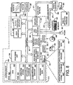
- FIG. 8 illustrates an example of a suitable computing system environment in which the Bayesian two-color image demosaicer and method may be implemented.
- the computing system environment 800 is only one example of a suitable computing environment and is not intended to suggest any limitation as to the scope of use or functionality of the invention. Neither should the computing environment 800 be interpreted as having any dependency or requirement relating to any one or combination of components illustrated in the exemplary operating environment.
- the Bayesian two-color image demosaicer and method is operational with numerous other general purpose or special purpose computing system environments or configurations.
- Examples of well known computing systems, environments, and/or configurations that may be suitable for use with the indirection texture magnification system and method include, but are not limited to, personal computers, server computers, hand-held, laptop or mobile computer or communications devices such as cell phones and PDA's, multiprocessor systems, microprocessor-based systems, set top boxes, , programmable consumer electronics, network PCs, minicomputers, mainframe computers, distributed computing environments that include any of the above systems or devices, and the like.
- the Bayesian two-color image demosaicer and method may be described in the general context of computer-executable instructions, such as program modules, being executed by a computer.
- program modules include routines, programs, objects, components, data structures, etc., that perform particular tasks or implement particular abstract data types.
- the Bayesian two-color image demosaicer and method may also be practiced in distributed computing environments where tasks are performed by remote processing devices that are linked through a communications network.
- program modules may be located in both local and remote computer storage media including memory storage devices.
- an exemplary system for Bayesian two-color image demosaicer and method includes a general-purpose computing device in the form of a computer 810 (the first computing device 270 in FIG. 1 and the second computing device 295 in FIG. 2 are examples of the computer 810).
- Components of the computer 810 may include, but are not limited to, a processing unit 820 (such as a central processing unit, CPU), a system memory 830, and a system bus 821 that couples various system components including the system memory to the processing unit 820.
- the system bus 821 may be any of several types of bus structures including a memory bus or memory controller, a peripheral bus, and a local bus using any of a variety of bus architectures.
- bus architectures include Industry Standard Architecture (ISA) bus, Micro Channel Architecture (MCA) bus, Enhanced ISA (EISA) bus, Video Electronics Standards Association (VESA) local bus, and Peripheral Component Interconnect (PCI) bus also known as Mezzanine bus.
- ISA Industry Standard Architecture
- MCA Micro Channel Architecture
- EISA Enhanced ISA
- VESA Video Electronics Standards Association
- PCI Peripheral Component Interconnect
- the computer 810 typically includes a variety of computer readable media.
- Computer readable media can be any available media that can be accessed by the computer 810 and includes both volatile and nonvolatile media, removable and non-removable media.
- Computer readable media may comprise computer storage media and communication media.
- Computer storage media includes volatile and nonvolatile removable and non-removable media implemented in any method or technology for storage of information such as computer readable instructions, data structures, program modules or other data.
- Computer storage media includes, but is not limited to, RAM, ROM, EEPROM, flash memory or other memory technology, CD-ROM, digital versatile disks (DVD) or other optical disk storage, magnetic cassettes, magnetic tape, magnetic disk storage or other magnetic storage devices, or any other medium which can be used to store the desired information and which can be accessed by the computer 810.
- Communication media typically embodies computer readable instructions, data structures, program modules or other data in a modulated data signal such as a carrier wave or other transport mechanism and includes any information delivery media.
- modulated data signal means a signal that has one or more of its characteristics set or changed in such a manner as to encode information in the signal.
- communication media includes wired media such as a wired network or direct-wired connection, and wireless media such as acoustic, RF, infrared and other wireless media. Combinations of any of the above should also be included within the scope of computer readable media.
- the system memory 830 includes computer storage media in the form of volatile and/or nonvolatile memory such as read only memory (ROM) 831 and random access memory (RAM) 832.
- ROM read only memory
- RAM random access memory
- BIOS basic input/output system 833
- RAM 832 typically contains data and/or program modules that are immediately accessible to and/or presently being operated on by processing unit 820.
- FIG. 8 illustrates operating system 834, application programs 835, other program modules 836, and program data 837.
- the computer 810 may also include other removable/non-removable, volatile/nonvolatile computer storage media.
- FIG. 8 illustrates a hard disk drive 841 that reads from or writes to non-removable, nonvolatile magnetic media, a magnetic disk drive 851 that reads from or writes to a removable, nonvolatile magnetic disk 852, and an optical disk drive 855 that reads from or writes to a removable, nonvolatile optical disk 856 such as a CD ROM or other optical media.
- removable/non-removable, volatile/nonvolatile computer storage media that can be used in the exemplary operating environment include, but are not limited to, magnetic tape cassettes, flash memory cards, digital versatile disks, digital video tape, solid state RAM, solid state ROM, and the like.
- the hard disk drive 841 is typically connected to the system bus 821 through a non-removable memory interface such as interface 840, and magnetic disk drive 851 and optical disk drive 855 are typically connected to the system bus 821 by a removable memory interface, such as interface 850.
- the drives and their associated computer storage media discussed above and illustrated in FIG. 8 provide storage of computer readable instructions, data structures, program modules and other data for the computer 810.
- hard disk drive 841 is illustrated as storing operating system 844, application programs 845, other program modules 846, and program data 847.
- operating system 844, application programs 845, other program modules 846, and program data 847 are given different numbers here to illustrate that, at a minimum, they are different copies.
- a user may enter commands and information into the computer 810 through input devices such as a keyboard 862 and pointing device 861, commonly referred to as a mouse, trackball or touch pad.
- Other input devices may include a microphone, joystick, game pad, satellite dish, scanner, radio receiver, or a television or broadcast video receiver, or the like. These and other input devices are often connected to the processing unit 820 through a user input interface 860 that is coupled to the system bus 821, but may be connected by other interface and bus structures, such as, for example, a parallel port, game port or a universal serial bus (USB).
- a monitor 891 or other type of display device is also connected to the system bus 821 via an interface, such as a video interface 890.
- computers may also include other peripheral output devices such as speakers 897 and printer 896, which may be connected through an output peripheral interface 895.
- the computer 810 may operate in a networked environment using logical connections to one or more remote computers, such as a remote computer 880.
- the remote computer 880 may be a personal computer, a server, a router, a network PC, a peer device or other common network node; and typically includes many or all of the elements described above relative to the computer 810, although only a memory storage device 881 has been illustrated in FIG. 8 .
- the logical connections depicted in FIG. 8 include a local area network (LAN) 871 and a wide area network (WAN) 873, but may also include other networks.
- LAN local area network
- WAN wide area network
- Such networking environments are commonplace in offices, enterprise-wide computer networks, intranets and the Internet.
- the computer 810 When used in a LAN networking environment, the computer 810 is connected to the LAN 871 through a network interface or adapter 870. When used in a WAN networking environment, the computer 810 typically includes a modem 872 or other means for establishing communications over the WAN 873, such as the internet.
- the modem 872 which may be internal or external, may be connected to the system bus 821 via the user input interface 860, or other appropriate mechanism.
- program modules depicted relative to the computer 810, or portions thereof may be stored in the remote memory storage device.
- FIG. 8 illustrates remote application programs 885 as residing on memory device 881. It will be appreciated that the network connections shown are exemplary and other means of establishing a communications link between the computers may be used.
Landscapes
- Engineering & Computer Science (AREA)
- Multimedia (AREA)
- Signal Processing (AREA)
- Physics & Mathematics (AREA)
- Spectroscopy & Molecular Physics (AREA)
- Color Television Image Signal Generators (AREA)
- Image Processing (AREA)
- Processing Of Color Television Signals (AREA)
Description
- Digital still cameras continue to increase in popularity and quality as the cost of such cameras continues to decline. Most digital still cameras use a single image sensor to capture color information for each pixel in a color image. The image sensor, which is typically a charge-coupled device (CCD) or a complementary metal oxide semiconductor (CMOS), is part of a sensor array that together represent the pixels of a color image.
- The image sensor can only generate information about a single color at a given pixel. A color image, however, is represented by combining three separate monochromatic images. In order to display a color image, all of the red, blue and green (RGB) color values are needed at each pixel. In order to obtain the other two missing colors, a technique must be used to estimate or interpolate the missing colors from surrounding pixels in the image. This class of estimation and interpolation techniques is called "demosaicing".
- The "demosaicing" term is derived from the fact that a color filter array (CFA) is used in front of the image sensors, with the CFA being arranged in a mosaic pattern. This mosaic pattern has only one color value for each of the pixels in the image. In order to obtain the full-color image, the mosaic pattern must be "demosalced". Thus, demosaicing is the technique of interpolating back the image captured with a mosaic-pattern CFA, so that a full RGB value can be associated with every pixel.
- More specifically, a single-sensor digital camera captures the image using an image sensor array that is preceded in the optical path by a CFA. A highly popular and common mosaic CFA is called the Bayer mosaic pattern. For each 2x2 set of pixels, two diagonally opposed pixels have green filters, and the other two pixels have red and blue filters. Since the color green (G) carries most of the luminance information for humans, its sampling rate is twice that of the color red (R) and the color blue (B).
- There are many types of demosaicing techniques currently available, such as bilinear interpolation, median filtering, vector CFA, gradient-based, and statistical modeling. However, each of these current demosaicing techniques produces visual and quantitatively measurable artifacts. These artifacts include aliasing or "zippering" artifacts, where every other pixel along an edge alternates between being considered on or off the edge, and color fringing, where yellows, purples, and cyans appear along or on sharp edges. Lukac R et al, "A robust, cost-effective post-processor for enhancing demosaicked camera images", relates to an efficient post processing/enhancement solution capable of reducing visual artifacts introduced during an image demosaicing process. Edge sensing weights and the original color filter array data are used to detect structural elements in the captured image, and correct color components generated by the demosaicing process using adaptive, spectral model based enhancement operations.
-
US 4 724 395 relates to technique for sensing sample colored image data and thereafter interpolating the sampled colored image data to provide image data in each color sample or each point or pixel at which the subject is sensed from which an image of the subject may be constructing having reduced color artifacts and fringing while reducing a blurring to the image that would otherwise be required to correct for such artifacts and fringing. - Wenmiao Lu et al, "Color filter array demosaiking: New method and performance measures", relates to a demosaicing technique which consists of two successive steps: an interpolation step that estimates missing color values by exploiting spatial and spectral correlations among neighboring pixels, and a post-processing step that suppresses noticeable demosaicing artifacts by adaptive median filtering.
- Malvar H S et al, "High-quality linear interpolation for demosaicing of bayer-patterned color images", relates to an interpolation technique for demosaicing of color images produced by a single-CCD digital camera.
- Yung-Yu Chuang et al, "A bayesian approach to digital matting", relates to a Bayesian framework for solving the matting problem, i.e. extracting a foreground element from a background image by estimating an opacity for each pixel of the foreground element.
- It is the object of the present invention to improve prior art systems. This object is solved by the subject matter of the independent claim. Preferred embodiments are defined by the dependent claims.
- This Summary is provided to introduce a selection of concepts in a simplified form that are further described below in the Detailed Description. This Summary Is not intended to identify key features or essential features of the claimed subject matter, nor is it intended to be used to limit the scope of the claimed subject matter.
- The Bayesian two-color image demosaicing method and system disclosed herein includes processing a digital color image to demosaic the image in such a way as to reduce image artifacts. The Bayesian two-color image demosaicing method and system employs an image model that models colors across an edge as a linear combination of the colors on each side. This decreases the possibility of inducing color fringing. Moreover, the statistical model used by the Bayesian two-color image demosaicing method and system Is not grid-based, thus easily allowing for extensions to both multi-image demosaicing for video processing and non-iterative super-resolution output sampling. By constraining the output image to a linear model, visible noise in smooth areas also is reduced while preserving sharp edges.
- The Bayesian two-color image demosaicing method and system is an improvement on and an enhancement of existing demosaicing techniques. The method and system performs a preliminary demosaicing pass on an image to assign each pixel in the image a fully specified RGB triple color value. The results of this preliminary pass then are improved by the Bayesian two-color image demosaicing method and system. The general idea is that within a small window or processing region (such as a 5x5 pixel "patch") that is centered on a pixel being processed, an assumption is made that there only exists two colors within that processing region. Assuming only two colors results in the virtual elimination of random colors in the final result. The color of the pixel then is restricted to be a linear combination of those two colors. This alleviates spurious colors that cause the color artifacts.
- Bayesian two-color image demosaicing method includes obtaining fully-specified RGB triple color values for each pixel in an image and then using the RGB triples to determine a final color value for each pixel. The final color value is a combination of and only has contribution from two colors. The two colors are found by clustering the fully-specified RGB triples into two clusters, taking the mean of each cluster, and calling the means of each cluster the favored two colors.
- Once the favored two colors are found, it must be determined how much contribution each color gives to the final color value. This is achieved by computing a fractional blended value for each pixel using samples in a processing region obtained from a Bayer color filter. Next, the maximum fractional blended value is found by finding the maximum probability of the fractional blended value given the set of samples. The final color value is computed from the maximum fractional blended value and the favored two colors.
- The Bayesian two-color image demosaicing method and system also can process multiple images to improve the demosaicing results. The multiple images first are registered with each other so that they are aligned. A reference image is selected, and the other images are reconstructed relative to the reference image. The processing is similar to the single image case, except that a technique is used to compensate for imperfect alignment of the images. The compensation technique uses a scaling factor to increase the variance of the Gaussian if the sum of the squared differences is large. This scaling factor varies based on the quality of the alignment algorithm.
- When using multiple images, the Bayesian two-color image demosaicing method and system also can sample at a finer resolution, which is known as super resolution. When super-resolving, the statistical clustering and local neighborhood sizes can be slightly shrunk to capture fine details. Other than that, the system operates similarly as it did in the multi-image demosaicing case.
- It should be noted that alternative embodiments are possible, and that steps and elements discussed herein may be changed, added, or eliminated, depending on the particular embodiment. These alternative embodiments include alternative steps and alternative elements that may be used, and structural changes that may be made, without departing from the scope of the invention.
- Referring now to the drawings in which like reference numbers represent corresponding parts throughout:
-
FIG. 1 is a block diagram illustrating a first exemplary implementation of the Bayesian two-color image demosaicing method and system disclosed herein. -
FIG. 2 is a block diagram illustrating a second exemplary implementation of the Bayesian two-color image demosaicing method and system disclosed herein. -
FIG. 3 is a general flow diagram illustrating the general operation of the Bayesian two-color image demosaicer shown inFIGS. 1 and2 . -
FIG. 4 is a detailed flow diagram illustrating the further details of the operation of the Bayesian two-color image demosaicing method shown inFIG. 3 . -
FIG. 5 is a flow diagram illustrating the favored two color computation process. -
FIG. 6 is a flow diagram illustrating details of the final color value computation process. -
FIG. 7 is a block diagram illustrating the details of the Bayesian two-color image demosaicer shown inFIGS. 1 and2 . -
FIG. 8 illustrates an example of a suitable computing system environment in which the Bayesian two-color image demosaicing method and system may be implemented. - In the following description of the Bayesian two-color image demosaicing method and system, reference is made to the accompanying drawings, which form a part thereof, and in which is shown by way of illustration a specific example whereby the Bayesian two-color image demosaicing method and system may be practiced. It is to be understood that other embodiments may be utilized and structural changes may be made without departing from the scope of the claimed subject matter.
-
FIGS. 1 and2 are block diagrams illustrating two exemplary implementations of the Bayesian two-color image demosaicing method and system disclosed herein. It should be noted thatFIGS. 1 and2 are merely two of several ways in which the Bayesian two-color image demosaicing method and system may be implemented and used. - Referring to
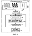
FIG. 1 , in the first exemplary implementation, the Bayesian two-color image demosaicer 200 resides on adigital camera system 210. In general, the Bayesian two-color image demosaicer 200 provides enhancement to a color image (not shown) subsequent to a preliminary demosaicing pass made using apreliminary pass demosaicer 220. More specifically, as shown inFIG. 1 , the Bayesian two-color image demosaicer 200 is part of thedigital camera system 210 that includes animage sensor array 225. Thearray 225 is made up of a plurality of image sensors, where each image sensor is capable of determining a single color value. - The
image sensor array 225 includes asensor substrate 230, a color filter array (CFA) 240, andlens 250. It should be noted that typically thelens 250 is disposed over theCFA 240, which in turn is disposed over thesubstrate 230, as indicated inFIGS. 1 and2 by the dashed lines. The light from the image to be captured (not shown) enters the digital camera system 210 (as shown by the arrows 255). The purpose of thelens 250 is to focus theincoming light 255 onto theimage sensor array 225. Each sensor in theimage sensor array 225 represents a pixel. TheCFA 240 changes the color response of each pixel. Thesensor substrate 230 captures the specific color incoming light (as dictated by the CFA 240) and generates an electrical signal. In this manner, theimage sensor array 225 samples the incoming light 255 from an image with red, green and blue sensors arranged in theimage sensor array 225. - Each pixel in the
image sensor array 225 is the output of a red, green or blue sensor. Thus, the sensor output is an electrical signal from each sensor that corresponds to a single color value for each pixel in theimage sensor array 225. The output is raw, mosaic-patternedpixel data 260. As mentioned above, in order to display the full color image, color information for red, green and blue colors must be obtained at each pixel. This is achieved by demosaicing, or the interpolating the missing color values in the mosaic-patternedpixel data 260. - The raw, mosaic-patterned
pixel data 260 is sent to a first computing device 270 located onboard thedigital camera system 210. Residing on the first computing device 270 are thepreliminary pass demosaicer 220 and the Bayesian two-color image demosaicer 200. Thepreliminary pass demosaicer 220 is used to interpolate an estimate of the missing color values. The output of thepreliminary pass demosaicer 220 ispixel data 280 containing full RGB color values for each pixel in the color image captured by thedigital camera system 210. The Bayesian two-color image demosaicer 200 receives thepixel data 280 and processes thisdata 280 as described in detail below. After processing by the Bayesian two-color image demosaicer 200, an enhanced color digital image having reducedimage artifacts 290 is obtained. - Referring now to
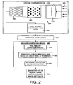
FIG. 2 , in the second exemplary implementation the Bayesian two-color image demosaicer 200 resides on asecond computing device 295 that is separate from thedigital camera system 210. The raw mosaic-patternedpixel data 260 is sent from thedigital camera system 210 to thesecond computing device 295. Thispixel data 260 typically is sent to thesecond computing device 295 via aninterface connection 297, which can be a USB interface, an IEEE 1394 interface, a Bluetooth® interface, or any other interface suitable for carrying theraw pixel data 260 from thedigital camera system 210 to thesecond computing device 295. As detailed below, the Bayesian two-color image demosaicer 200 uses the Bayesian two-color image demosaicing method to enhance thepixel data 260 and provides the enhanced color digital image having reducedimage artifacts 290. - The operation of the Bayesian two-
color image demosaicer 200 and method used therein shown inFIGS. 1 and2 now will be discussed.FIG. 3 is a general flow diagram illustrating the general operation of the Bayesian two-color image demosaicer 200. In general, the Bayesian two-color image demosaicing method inputs pixel color values for pixels in an image, processes each of the pixels, and outputs a processed image that has reduced image artifacts. - More specifically, as shown in
FIG. 3 , the Bayesian two-color image demosaicing method begins by obtaining a fully-specified red (R), green (G), and blue (B) triple color.values for each pixel in a digital color image (box 300). Fully-specified RGB triple means that the red, green, and blue color values are available for the pixel. Typically, the Bayesian two-color image demosaicing method obtains these fully-specified RGB triple color values by performing a preliminary demosaicing pass on the digital color image. The Bayesian two-color image demosaicing method then enhances the results of the preliminary demosaicing pass. - Next, the Bayesian two-color image demosaicing method determines a final color value for each pixel in the digital color image (box 310). The final color value is a combination or blend of two colors, where the two colors are obtained by using at least some of the fully-specified RGB triple color values. In other words, even though there may be several colors contained in the fully-specified RGB triple color values, only a combination of two of those color values is used in determining a final color value for the pixel being processed. The output is a final color value that is found for each of the pixels in the digital color image (box 320).
- The details of the Bayesian two-color image demosaicing method now will be discussed.
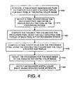
FIG. 4 is a detailed flow diagram illustrating the further details of the operation of the Bayesian two-color image demosaicing method shown inFIG. 3 . In particular, a preliminary demosaicing pass is performed to compute the fully-specified RGB triples for each pixel in the digital color image (box 400). Initially, there is a Bayer pattern for the image, in which there is only an R, a G, or a B color value for each pixel in the image. The preliminary demosaicing pass uses a demosaicing technique to obtain an actual full color (RGB) value at each one of the pixels in a processing region centered at a pixel being processed. In one embodiment, the preliminary demosaicing pass is performed using a bilinear interpolation technique. In alternative embodiments, other types of preliminary pass demosaicing techniques may be used, such as median filtering techniques, vector CFA techniques, gradient-based techniques, and statistical modeling techniques. When selecting a preliminary pass demosaicing technique, however, it should be noted that the technique that will give the best input also yields the best output by the Bayesian two-color image demosaicing method. - Next, a pixel is selected for processing and is defined as a processed pixel. In addition, a region around the processed pixel is defined as a processing region (box 410). The processing region (or "window" or "patch") typically is a 5x5 pixel patch, although other sizes are possible. In one embodiment, the patch size is odd, such that the processed pixel is centered in the processing region. By way of example, in a 5x5 processing regions, the processed pixel would be the center pixel of the 5x5 patch.
- Favored two colors then are computed for the processed pixel (box 420). This is achieved using the fully-specified RGB triples of each pixel in the processing region. As explained in detail below, the fully-specified RGB triples may contain several colors, but those colors are clustered into only two favored colors. A final color value for the processed pixel is computed using the favored two colors and the fully-specified RGB triples (box 430). The process of selecting a pixel, defining a processing region, computing the favored two colors, and computer a final color value all are repeated for the remainder of the pixels in the digital color image (box 440). The output of the Bayesian two-color image demosaicing method is an enhanced digital color image having reduced image artifacts (box 450).
-
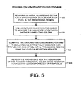
FIG. 5 is a flow diagram illustrating the favored two color computation process. In other words,FIG. 5 illustrates how the favored two colors are found from among the color values of pixels in the processing regions. The process begins by performing an initial clustering of the fully-specified RGB triples for each pixel in the processing region (box 500). Assuming that the processing region is 5x5 pixels, the goal is to find the favored two colors from among the 25 color values in the 5x5 processing region, and group these 25 color values into 2 favored colors. This can be done generally using any clustering technique. In one embodiment, a k-means technique is used because of its efficiency. The "k" in the k-means technique refers to the number of cluster types, where, in this case, k=2. The k-means clustering technique is a balance between accuracy and speed. The k-means clustering technique is well known by those having skill in the art, and will not be discussed in further detail. In alternative embodiments, an expectation maximization (EM) technique or mean shift technique is used. - The one problem, however, with the k-means technique, is that an outlier can adversely affect the results. An outlier is a data point that is located far from the rest of the data. A statistical distribution expects data points to fall within a specific range, and those that do not are called outliers. In order to correct for outliers, the favored two color computation process includes an outlier rejection technique. The outlier rejection technique is used to minimize the influence of outliers on the favored two colors (box 510).
- The favored two colors then are computed by updating the clustering of the fully-specified RGB triples for each pixel in the processing region by using the outlier rejection results (box 520). The processing then is repeated for the remainder of the pixels in the digital color image (box 530). Favored two colors for each pixel then are obtained for each pixel in the image.
-
FIG. 6 is a flow diagram illustrating details of the final color value computation process. The process begins by defining a fractional blended value for the processed pixel that specifies the contribution of each of the favored two colors to the final color value (box 600). Thus, the fractional blended value determines how much contribution the final color value of the pixel gets from each of the favored two colors. - A maximum fractional blended value then is determined for the processed pixel (box 610). The maximum fractional blended value is defined as a blend or combination of the favored two colors that maximizes a probability of the fractional blended value using each of the fully-specified RGB triples in the processing region. This involves possibly looking for more than one set of colors, and then trying all those colors out to see which one gives the maximum value. For example, imagine trying three colors, J, K, and L, and trying all combinations of J, K, and L, and seeing which one gives the highest probability. Thus, out of all the colors, the favored two colors are the best two colors that explain the processed pixel. The "best" two colors means the two colors that maximizes the argument of the maximum (or "arg max") of equation (3) given below. The arg max is the value of a given argument for which the value of a given expression attains its maximum value.
- A final color value then is computed for the processed pixel using the favored two colors and the maximum fractional blended value (box 620). This final color value is set forth in equation (1) given below. The above processing is repeated for the remainder of the pixels in the digital color image in order to obtain a final color value for each of the pixels (box 630).
- In order to more fully understand the Bayesian two-color image demosaicing method and system disclosed herein, the operational details of an exemplary working example are presented. It should be noted that this working example is only one way in which the Bayesian two-color image demosaicing method and system may be implemented.
- A central assumption to processing by the Bayesian two-color image demosaicing method and system is that at most two representative colors exist within a local neighborhood. The final color value of every pixel within that neighborhood is either one of the representative colors or is a combination of both. In this working example, the combination of the representative colors was a linear combination. Although this assumption was violated in areas where more than two different colors meet, such occurrences were relatively rare. Thus, the Bayesian two-color image demosaicing method and system is very robust.
- To discover the underlying two color model at each pixel, the neighborhood surrounding each pixel was clustered into those two colors. The Bayer image provided only a single channel sample, leaving two unknown RGB triple color values and an unknown blending coefficient to specify the model. In this working example, a weighted k-means technique was used in which the weight is the inverse Euclidean distance from each sample to the center of the kernel. Note that cluster sizes are not balanced, so a single pixel detail in an otherwise smooth area can be preserved. Also, clustering can be performed in other color spaces, such as Lαβ or XYZ, but processing in these spaces made little difference in the accuracy of the clusters.
- The neighborhood size of samples to cluster is a function of how large color details appear in the source image. In this working example, a two pixel radius around the kernel's center was found to work well. This supplied a sufficient number of samples from each of the Bayer color channels.
- Because it is possible that more than two colors may exist in a local image area or that significant noise may be present, the Bayesian two-color image demosaicing method and system also used an outlier rejection technique. Using the mean and variance of the clusters, samples that were outside of a single standard deviation of their closest cluster mean were rejected. The k-means technique then was repeated to obtain cleaner cluster means. This provided better reproduction where color values changed rapidly away from the kernel center.
- The major factor in the quality of clustering is the choice of a preliminary pass demosaicing technique used for the "bootstrapping" demosaicing to make clustering tractable. Although many types of preliminary pass demosaicing techniques may be used (as listed above), there are qualities that improve performance. The first is preservation or accentuation of high frequency features. Techniques such as bilinear interpolation and median interpolation have a tendency to low-pass filter, which should be avoided. Alternately, algorithms that preserve high frequencies are prone to generate edge fringing and aliasing. In this working example, a high-quality linear interpolation (HQLI) technique was used in the preliminary pass demosaicing because it preserved high frequencies and did not generate many fringing artifacts.
- The two color model provides two RGB priors,
J andK , for each pixel x in the image. The color C of pixel x was assumed to be a linear combination these two colors, given by:
Equation (1) is a blending equation, and computes the final color value, C, for the pixel x. - Within a neighborhood of the pixel x, the Bayer sensor gives a set of samples si ε S. The index of the RGB color channel specified by sample si is denoted by t i, and a is the fractional blended value.
- If
J ti specifies the by t ith color channel for colorJ , and similarly forK and C, then the unknown value of the fractional blended value, a, could be computed directly from the Bayer sample sx at location x (the central pixel) as:
However, if the difference betweenJ x andK x is small, the estimate of a will be inaccurate due to discretization and image noise. Note that s is an element of S for si , where, for a 5x5 processing regions, i ranges from 1-25, such that there are 25 si's. The si's are only for a single channel (or color), and the color is specified by the ti's (either R, G, or B). - A more robust estimate of a using the entire set of samples S is desired. In other words, it is desired to find the most likely value (or maximum fractional blended value) α̂ of α given a sample set S and color priors
J andK :
For equation (3), theJ andK are the favored two colors. In color space, it can be imagined that a line is drawn fromJ toK , and that the fractional blended value a varies from 0 to 1 and beyond. This means that α = 0 atK and α = 1 atJ . In other words, equation (3) finds the arg max of a that maximizes the probability of α, given S, where S is the set of all the samples of colors that are in the processing regions (a 5x5 patch in this working example). It should be noted that S only contains samples that are actually sampled, and not obtained by demosaicing. - Using Bayes' theorem, and assuming
J andK are independent of S and α, equation (3) can be rearranged to yield:
Assuming all si's are independent, it is found:
J ,K , and a specify a predicted color, C* = (1 - α)J + αK for pixel x. Assuming an independent identical distribution (i.i.d.)for neighboring color noise, the relationship between C * ti and si can be modeled using a normal distribution:
Equation (6) computes the probability using a Gaussian. C* is the color computed given an α. The distribution between neighboring pixels is highly kurtotic, but for computational efficiency, a Gaussian distribution is assumed. The variance σ i 2 is dependent on two factors: (1) the global per-channel image noise σN ; and, (2) the pixel distance between x and si . It is assumed that pixel colors are locally similar, and less similar farther away. Thus, the variance between si and Cti increases as their distance in image space increases. In one embodiment, the variance σ i is computed as:
where Δ d is the pixel distance between x and si , and λ is a constant that, in this working example, is empirically set to 6. Thus, equation (7) states that the variance increases linearly with distance from the center pixel (the processed pixel), or the pixel in the center of the processing region. In alternative embodiments, other monotonically increasing functions of distance may be used. - The width of the Gaussian, or the variance, σ2, indicates how much influence a particular sample has on the final result. Another way to think about it is that it is the certainty of the sample. If there is uncertainty about a sample, its Gaussian will have a large width (or large variance, σ2). Conversely if there is certainty about a sample, its Gaussian will have a narrow width (or small variance, σ2).
- Equation (7) is a function that states that the variance increases with the distance from the processed (or center) pixel, around which the processing region is centered. In other words, pixels that are closer to the center pixel are more desirable and have a higher weight. And the more variance, the less influence that pixel or sample has on the final result. Thus, the variance should increase with the distance from the center pixel, by some function. Although a linear function in the form of equation (7) was used in this working example, other types of functions that state the variance in a similar way could also be used.
- Since the value of si is known and it is desired to compute the value of α that maximizes equation (6), it is useful to rearrange it as follows:

Equation (8) is a Gaussian over α with mean α i and variance

It is actually desired to solve for α, so we rearrange the equations to get equation (10). In particular, equations (5)and (8) can be combined to yield:
The optimal value of α for P(si |α,J ,K ) is:
In practice, the contribution of color components is ignored where the absolute difference betweenJ ti andK ti is less than 2.0. - When solving equations (10) and (11), the α i's, and the σ i's need to be found, where the σ2 i's are the variances associated with each of the samples. The optimal fractional blended value, α*, then is found, which is the optimal α value. α* then is used to compute the final color value. A slight penalty is imposed for an a value that is not 0 or 1. Consequently, in one embodiment, a has a value of 0, while in an alternative embodiment, a has a value of 1.
- Next, a determination is made as to which α (0, 1, or α*) yields the highest value for equation (5). In other words, equation (5) is evaluated with each of these three α's to determine which a gives the highest answer. For equation (10), the αi's and the σαi's then are computed. The αi's are computed using equation (9). Given the sample si , equation (9) computes the value of α. In other words, α is what the sample si , says that αi should be. In equation (10), a product of the αi's is used. If a Gaussian is multiplied by a Gaussian, another Gaussian is obtained. The value of the peak of the Gaussian all the Gaussians of the each of the 25 samples are multiplied together is represented by the αi*, given by equation (11). It can be shown that the mean of the product of all the Gaussians is going to be equation (11), which is a weighted averaging.
- Finally, to find the value of α̂ in equation (3), a prior must be defined over α. P(α). Given that most pixels within an image only get contribution from a single color, α is biased to have a value of 0 or 1:

where η is always less than 1 (η<1). The value of η depends upon the amount of smoothing desired. Given a large amount of image noise, η≈1. - Since the α prior function is flat with two impulses, only the value of equation (3)at three points:0,1,and α * needs to be examined. Whichever is the maximum is assigned as the final value α̂ for the pixel being processed, with a

- The quantitative error of this approach can be further decreased by forcing the red, green, or blue at an output pixel to be the value originally captured by the sensor, while setting the other two channels to be consistent with α̂. Because λ weights the central sample heavily, it is unlikely that these two values will be very different. Also, if the output sampling is done on a grid differing from the input grid, a source Bayer sample is not available at each pixel.
- Using the gridless Bayesian solution, information from multiple images can be introduced into the model without significantly altering the methodology. These supporting images are assumed to be similar, but not exactly the same, such as from subsequent video frames. Furthermore, these additional Bayer samples can be used without resampling them. To use supporting images, a per-image projective mapping must be computed to register each image to the first image.
- The Bayesian two-color image demosaicing method and system can get samples from multiple images, as long as they are registered. Registering the images allows multiple images of a scene to be aligned together so they can be used. However, when the image are aligned they may not be oriented the same. The Bayesian two-color image demosaicing method and system selects a reference image and reconstructs the other images relative to the reference image. The processing region then becomes circular, and samples are taken within a certain radius of the processed (or center) pixel.
- In general, better results are obtained by using more images. However, there is a trade-off between processing time and quality. In one embodiment, the number of images used is 3, such that the processing time is fairly short and the quality is very good. In alternative embodiments, the number of images used may be more or less than three.
- As more images are added, the neighborhood of samples used can be shrunk while still maintaining sufficient samples to cluster into
J andK . By doing so, the likelihood of it containing more than two representative colors is reduced. Thus, if an R, G, and B sample each appear close to the sample being reconstructed, nearest neighbor interpolatioh combination of Bayer samples could be used. The notion of using weighted clustering and reconstruction remain the same as with a single input image. Once registered, even if the same color channel appears at the same pixel location, there is still a benefit, namely, noise reduction. - By including supporting images, there is a risk of introducing bad or misleading data. The global projective mapping does not account for all scene changes (moving camera, moving objects, changes in lighting conditions and object appearance). Errors in registration could occur. To reduce such errors, it is ensured that only data from the reference and supporting images that are locally similar are combined. Similarity is measured in RGB space using a Sum of Absolute Differences (SAD) technique over a local window of 7 ×7, denoted as ε.
- Multiple images are handled by adjusting the definition of σ i to include the correlation error between the reference and supporting images:

The term (1 +τε) is the mismatch penalty, with T =0.1 in this working example. ε is the sum of squared differences. - When the multiple images are aligned, the alignment may not be perfect. To compensate for this, a sum of squares differences is used. Instead of using equation (7), equation (13) is used. The only difference is the last term, (1+τε). The τ is a scaling factor. So the last term in equation (13), (1+τε), states that the variance of the Gaussian is increased if the sum of the squared differences is large.
- The term τ is how much the sum of the squared differences value is weighed. It is determined empirically. In one embodiment, T equals approximately 0.1. In alternative embodiments, othervalues of T may be used. However, it is important that T not be weighed too heavily. If T is too large, then information from other images may never be used. If T is too small, then information from other images may be used even if the images are not properly aligned. Thus, a balance must be found. The term T varies based on the quality of the alignment algorithm.
- To implement multi-image demosaicing, all that is required is adding nearby Bayer samples in the supporting images to the set S and using the above variance equation. It should be noted that the samples in S are the Bayer sensor samples because using the original samples avoids the need for any resampling.
- Another advantage of the statistical, grid-less approach of the Bayesian two-color image demosaicing method and system is that any sampling grid can be used for the reconstruction, such as a sampling grid having a greater resolution than the original images. Because floating-point Euclidean distances are used for the statistical measures, a continuous value of α can be generated anywhere in the image. Due to the alignment of samples from multiple images, the value of α may encode edges and sharpness between the pixels in the original grid. This can be exploited to handle super-resolution within the framework of the Bayesian two-color image demosaicing method and system.
- When super-resolving, the statistical clustering and local neighborhood sizes can be slightly shrunk to capture fine details. Other than that, the Bayesian two-color image demosaicing method and system operates similarly as it did in the multi-image demosaicing case.
- The structure of the Bayesian two-
color image demosaicer 200 now will be discussed. In order to more fully understand the structure of the Bayesian two-color image demosaicer 200, the details of an exemplary embodiment are presented. However, it should be noted that this exemplary embodiment is only one of several ways in which the Bayesian two-color image demosaicer 200 may be implemented and used. -
FIG. 7 is a block diagram illustrating the details of the Bayesian two-color image demosaicer 200 shown inFIGS. 1 and2 . In general, the Bayesian two-color image demosaicer 200 processes a digital color image having fully-specified RGB color values for each pixel, finds a final color value for each pixel as a combination of two colors, and outputs the process digital color image having reduced artifacts. Specifically, input to the Bayesian two-color image demosaicer 200 is a pixel data containing fully-specified RGB data for each pixel in thedigital color image 280. As explained above, this data is obtained by making a preliminary demosaicing pass on the image. In one embodiment, preliminary demosaicing pass is performed using a high-quality linear interpolation demosaicing technique. Alternatively, other types of demosaicing techniques may be used, such as bilinear interpolation. - The Bayesian two-
color image demosaicer 200 includes a processedpixel selector 700, which selects a pixel from the image to be processed. Eventually all the pixels in the image are processed, but the processedpixel selector 700 picks one pixel at a time for processing. A processingregion definition module 710 defines a processing region (or patch) around the processed pixel. Typically, the processed pixel is at the center of the processing region. In one embodiment, the processing region is a 5x5 pixel area. In alternative embodiments, processing regions having other sizes (such as a 3x3 pixel area or a 7x7 pixel area) may be used. - The Bayesian two-
color image demosaicer 200 also includes aclustering module 720 that determines the favored two colors used to define a final color value for the processed pixel. The clustering module uses a clustering technique to cluster the RGB color values from the pixels in the processing region into two clusters. The mean of each of the two clusters becomes the favored two colors. In one embodiment, a k-means clustering technique with an outlier rejection stage is used for clustering. In alternative embodiments, other types of clustering technique may be used. - The
demosaicer 200 also includes a contribution andcombination module 730 that determines how much of each of the favored two colors is used in the final color value, and combines the favored two colors to obtain the final color value. Themodule 730 find the contribution of each of the favored two colors by defining a maximum fractional blended value that maximizes the probability of a fractional blended value given a sample set. The sample set contains sampled color values from pixels in the processing region. Themodule 730 then combines the maximum fractional blended value and the favored two colors to compute the final color value for the processed pixel. In one embodiment, the favored two colors are linearly combined. In alternative embodiments, the favored two colors are combined in a non-linear manner. The processing by the Bayesian two-color image demosaicer 200 is repeated for each pixel in the image. The output is an enhanced digital color image having reducedimage artifacts 290. - The Bayesian two-
color image demosaicer 200 and method used therein are designed to operate in a computing environment. The following discussion is intended to provide a brief, general description of a suitable computing environment in which the Bayesian two-color image demosaicer and method may be implemented. -
FIG. 8 illustrates an example of a suitable computing system environment in which the Bayesian two-color image demosaicer and method may be implemented. Thecomputing system environment 800 is only one example of a suitable computing environment and is not intended to suggest any limitation as to the scope of use or functionality of the invention. Neither should thecomputing environment 800 be interpreted as having any dependency or requirement relating to any one or combination of components illustrated in the exemplary operating environment. - The Bayesian two-color image demosaicer and method is operational with numerous other general purpose or special purpose computing system environments or configurations. Examples of well known computing systems, environments, and/or configurations that may be suitable for use with the indirection texture magnification system and method include, but are not limited to, personal computers, server computers, hand-held, laptop or mobile computer or communications devices such as cell phones and PDA's, multiprocessor systems, microprocessor-based systems, set top boxes, , programmable consumer electronics, network PCs, minicomputers, mainframe computers, distributed computing environments that include any of the above systems or devices, and the like.
- The Bayesian two-color image demosaicer and method may be described in the general context of computer-executable instructions, such as program modules, being executed by a computer. Generally, program modules include routines, programs, objects, components, data structures, etc., that perform particular tasks or implement particular abstract data types. The Bayesian two-color image demosaicer and method may also be practiced in distributed computing environments where tasks are performed by remote processing devices that are linked through a communications network. In a distributed computing environment, program modules may be located in both local and remote computer storage media including memory storage devices. With reference to
FIG. 8 , an exemplary system for Bayesian two-color image demosaicer and method includes a general-purpose computing device in the form of a computer 810 (the first computing device 270 inFIG. 1 and thesecond computing device 295 inFIG. 2 are examples of the computer 810). - Components of the
computer 810 may include, but are not limited to, a processing unit 820 (such as a central processing unit, CPU), asystem memory 830, and asystem bus 821 that couples various system components including the system memory to theprocessing unit 820. Thesystem bus 821 may be any of several types of bus structures including a memory bus or memory controller, a peripheral bus, and a local bus using any of a variety of bus architectures. By way of example, and not limitation, such architectures include Industry Standard Architecture (ISA) bus, Micro Channel Architecture (MCA) bus, Enhanced ISA (EISA) bus, Video Electronics Standards Association (VESA) local bus, and Peripheral Component Interconnect (PCI) bus also known as Mezzanine bus. - The
computer 810 typically includes a variety of computer readable media. Computer readable media can be any available media that can be accessed by thecomputer 810 and includes both volatile and nonvolatile media, removable and non-removable media. By way of example, and not limitation, computer readable media may comprise computer storage media and communication media. Computer storage media includes volatile and nonvolatile removable and non-removable media implemented in any method or technology for storage of information such as computer readable instructions, data structures, program modules or other data. - Computer storage media includes, but is not limited to, RAM, ROM, EEPROM, flash memory or other memory technology, CD-ROM, digital versatile disks (DVD) or other optical disk storage, magnetic cassettes, magnetic tape, magnetic disk storage or other magnetic storage devices, or any other medium which can be used to store the desired information and which can be accessed by the
computer 810. Communication media typically embodies computer readable instructions, data structures, program modules or other data in a modulated data signal such as a carrier wave or other transport mechanism and includes any information delivery media. - Note that the term "modulated data signal" means a signal that has one or more of its characteristics set or changed in such a manner as to encode information in the signal. By way of example, and not limitation, communication media includes wired media such as a wired network or direct-wired connection, and wireless media such as acoustic, RF, infrared and other wireless media. Combinations of any of the above should also be included within the scope of computer readable media.
- The
system memory 830 includes computer storage media in the form of volatile and/or nonvolatile memory such as read only memory (ROM) 831 and random access memory (RAM) 832. A basic input/output system 833 (BIOS), containing the basic routines that help to transfer information between elements within thecomputer 810, such as during start-up, is typically stored inROM 831.RAM 832 typically contains data and/or program modules that are immediately accessible to and/or presently being operated on by processingunit 820. By way of example, and not limitation,FIG. 8 illustrates operating system 834, application programs 835,other program modules 836, andprogram data 837. - The
computer 810 may also include other removable/non-removable, volatile/nonvolatile computer storage media. By way of example only,FIG. 8 illustrates ahard disk drive 841 that reads from or writes to non-removable, nonvolatile magnetic media, amagnetic disk drive 851 that reads from or writes to a removable, nonvolatilemagnetic disk 852, and anoptical disk drive 855 that reads from or writes to a removable, nonvolatileoptical disk 856 such as a CD ROM or other optical media. - Other removable/non-removable, volatile/nonvolatile computer storage media that can be used in the exemplary operating environment include, but are not limited to, magnetic tape cassettes, flash memory cards, digital versatile disks, digital video tape, solid state RAM, solid state ROM, and the like. The
hard disk drive 841 is typically connected to thesystem bus 821 through a non-removable memory interface such asinterface 840, andmagnetic disk drive 851 andoptical disk drive 855 are typically connected to thesystem bus 821 by a removable memory interface, such asinterface 850. - The drives and their associated computer storage media discussed above and illustrated in
FIG. 8 , provide storage of computer readable instructions, data structures, program modules and other data for thecomputer 810. InFIG. 8 , for example, hard disk drive 841.is illustrated as storingoperating system 844,application programs 845,other program modules 846, andprogram data 847. Note that these components can either be the same as or different from operating system 834, application programs 835,other program modules 836, andprogram data 837.Operating system 844,application programs 845,other program modules 846, andprogram data 847 are given different numbers here to illustrate that, at a minimum, they are different copies. A user may enter commands and information into thecomputer 810 through input devices such as akeyboard 862 andpointing device 861, commonly referred to as a mouse, trackball or touch pad. - Other input devices (not shown) may include a microphone, joystick, game pad, satellite dish, scanner, radio receiver, or a television or broadcast video receiver, or the like. These and other input devices are often connected to the
processing unit 820 through auser input interface 860 that is coupled to thesystem bus 821, but may be connected by other interface and bus structures, such as, for example, a parallel port, game port or a universal serial bus (USB). A monitor 891 or other type of display device is also connected to thesystem bus 821 via an interface, such as avideo interface 890. In addition to the monitor, computers may also include other peripheral output devices such asspeakers 897 andprinter 896, which may be connected through an outputperipheral interface 895. - The
computer 810 may operate in a networked environment using logical connections to one or more remote computers, such as aremote computer 880. Theremote computer 880 may be a personal computer, a server, a router, a network PC, a peer device or other common network node; and typically includes many or all of the elements described above relative to thecomputer 810, although only amemory storage device 881 has been illustrated inFIG. 8 . The logical connections depicted inFIG. 8 include a local area network (LAN) 871 and a wide area network (WAN) 873, but may also include other networks. Such networking environments are commonplace in offices, enterprise-wide computer networks, intranets and the Internet. - When used in a LAN networking environment, the
computer 810 is connected to theLAN 871 through a network interface oradapter 870. When used in a WAN networking environment, thecomputer 810 typically includes amodem 872 or other means for establishing communications over theWAN 873, such as the internet. Themodem 872, which may be internal or external, may be connected to thesystem bus 821 via theuser input interface 860, or other appropriate mechanism. In a networked environment, program modules depicted relative to thecomputer 810, or portions thereof, may be stored in the remote memory storage device. By way of example, and not limitation,FIG. 8 illustrates remote application programs 885 as residing onmemory device 881. It will be appreciated that the network connections shown are exemplary and other means of establishing a communications link between the computers may be used. - The foregoing Detailed Description has been presented for the purposes of illustration and description. Many modifications and variations are possible in light of the above teaching. It is not intended to be exhaustive or to limit the subject matter described herein to the precise form disclosed. Although the subject matter has been described in language specific to structural features and/or methodological acts, it is to be understood that the subject matter defined in the appended claims is not necessarily limited to the specific features or acts described above. Rather, the specific features and acts described above are disclosed as example forms of implementing the claims appended hereto.
Claims (7)
- A method for processing a digital color image (260), comprising:using (400) a preliminary pass demosaicing technique to obtain fully-specified RGB triple color values for each pixel in the digital color image;defining (410) a processing region in the digital color image centered at a pixel being processed;clustering (500) color values of pixels in the processing region into two favored colors using a k-means clustering technique; anddetermining (310) a final color value for each pixel as a combination of the two favored colors using the fully-specified RGB triple color values to obtain an enhanced digital color image having reduced image artifacts (290), wherein the final color value is determined for the processed pixel.
- The method of claim 1, further comprising using a bilinear interpolation demosaicing technique (220) to obtain the fully-specified RGB triple color values for each pixel (280).
- The method of claim 1, further comprising using (510) an outlier rejection technique with the clustering technique to improve clustering results.
- The method of claim 1, further comprising determining (730) how much contribution each of the favored two colors gives to the final color value.
- The method of claim 4, further comprising defining (600) a fractional blended value that specifies the contribution of each of the favored two colors to the final color value.
- The method of claim 5, further comprising determining (610) a maximum fractional blended value for the processed pixel defined as a blend of the favored two colors that maximizes a probability of the fractional blended value given each of the pixel color values in the processing region.
- The method of claim 5, further comprising using (620) the maximum fractional blended value for each pixel and the favored two colors for each pixel to obtain the final color value for each of the pixels in the digital color image.
Applications Claiming Priority (2)
| Application Number | Priority Date | Filing Date | Title |
|---|---|---|---|
| US11/343,581 US7706609B2 (en) | 2006-01-30 | 2006-01-30 | Bayesian demosaicing using a two-color image |
| PCT/US2007/001982 WO2007089519A1 (en) | 2006-01-30 | 2007-01-25 | Bayesian demosaicing using a two-color image |
Publications (3)
| Publication Number | Publication Date |
|---|---|
| EP1967010A1 EP1967010A1 (en) | 2008-09-10 |
| EP1967010A4 EP1967010A4 (en) | 2012-01-18 |
| EP1967010B1 true EP1967010B1 (en) | 2013-07-17 |
Family
ID=38321691
Family Applications (1)
| Application Number | Title | Priority Date | Filing Date |
|---|---|---|---|
| EP07716996.9A Not-in-force EP1967010B1 (en) | 2006-01-30 | 2007-01-25 | image demosaicing method |
Country Status (8)
| Country | Link |
|---|---|
| US (1) | US7706609B2 (en) |
| EP (1) | EP1967010B1 (en) |
| JP (1) | JP4527172B2 (en) |
| KR (1) | KR101183371B1 (en) |
| CN (1) | CN101375611B (en) |
| BR (1) | BRPI0706282A2 (en) |
| MY (1) | MY149682A (en) |
| WO (1) | WO2007089519A1 (en) |
Families Citing this family (24)
| Publication number | Priority date | Publication date | Assignee | Title |
|---|---|---|---|---|
| US8165389B2 (en) | 2004-03-15 | 2012-04-24 | Microsoft Corp. | Adaptive interpolation with artifact reduction of images |
| GB2426881B (en) * | 2005-06-01 | 2010-12-29 | Snell & Wilcox Ltd | Method and apparatus for spatial interpolation of colour images |
| KR100793288B1 (en) * | 2007-05-11 | 2008-01-14 | 주식회사 코아로직 | Image processing apparatus and method |
| US8031970B2 (en) * | 2007-08-27 | 2011-10-04 | Arcsoft, Inc. | Method of restoring closed-eye portrait photo |
| US8035704B2 (en) | 2008-01-03 | 2011-10-11 | Aptina Imaging Corporation | Method and apparatus for processing a digital image having defective pixels |
| JP5047048B2 (en) * | 2008-04-30 | 2012-10-10 | キヤノン株式会社 | Image processing apparatus, imaging apparatus, control method, program, and storage medium |
| US11119396B1 (en) | 2008-05-19 | 2021-09-14 | Spatial Cam Llc | Camera system with a plurality of image sensors |
| US10585344B1 (en) | 2008-05-19 | 2020-03-10 | Spatial Cam Llc | Camera system with a plurality of image sensors |
| US12140855B2 (en) | 2008-05-19 | 2024-11-12 | Peter Lablans | Camera system with a plurality of image sensors |
| US8355042B2 (en) | 2008-10-16 | 2013-01-15 | Spatial Cam Llc | Controller in a camera for creating a panoramic image |
| US8781250B2 (en) * | 2008-06-26 | 2014-07-15 | Microsoft Corporation | Image deconvolution using color priors |
| TWI423666B (en) * | 2008-12-31 | 2014-01-11 | Altek Corp | Image elimination method for image sequence |
| US8462171B2 (en) * | 2009-02-06 | 2013-06-11 | Micrososft Corporation | Saturation contrast image enhancement |
| US8666180B2 (en) | 2009-12-04 | 2014-03-04 | Stc.Unm | System and methods of compressed sensing as applied to computer graphics and computer imaging |
| US8345132B2 (en) * | 2010-07-23 | 2013-01-01 | Omnivision Technologies, Inc. | Image sensor with dual element color filter array and three channel color output |
| US8553978B2 (en) * | 2010-11-03 | 2013-10-08 | Csr Technology Inc. | System and method for providing multi resolution purple fringing detection and correction |
| US8730329B2 (en) * | 2011-07-11 | 2014-05-20 | Qualcomm, Incorporated | Automatic adaptive image sharpening |
| US20130031063A1 (en) * | 2011-07-26 | 2013-01-31 | International Business Machines Corporation | Compression of data partitioned into clusters |
| US9224362B2 (en) | 2013-03-14 | 2015-12-29 | Microsoft Technology Licensing, Llc | Monochromatic edge geometry reconstruction through achromatic guidance |
| US9336570B2 (en) * | 2014-05-15 | 2016-05-10 | The United States Of America, As Represented By The Secretary Of The Navy | Demosaicking system and method for color array based multi-spectral sensors |
| US9219870B1 (en) * | 2014-07-31 | 2015-12-22 | Apple Inc. | Sensor data rescaler for image signal processing |
| FR3046711B1 (en) | 2016-01-08 | 2018-02-16 | Stmicroelectronics (Grenoble 2) Sas | COMPRESSION AND DECOMPRESSION OF VIDEO DATA |
| CN111681191B (en) * | 2020-05-11 | 2024-02-27 | 安徽百诚慧通科技股份有限公司 | Color image demosaicing method, system and storage medium based on FPGA |
| KR102488627B1 (en) * | 2021-11-08 | 2023-01-18 | 청주대학교 산학협력단 | Automatic converting method for PIPO painting image and automatic converting system for PIPO painting image using thereof |
Family Cites Families (16)
| Publication number | Priority date | Publication date | Assignee | Title |
|---|---|---|---|---|
| US3871065A (en) * | 1972-08-02 | 1975-03-18 | Gen Co Ltd | Thermal printing process |
| US4642678A (en) | 1984-09-10 | 1987-02-10 | Eastman Kodak Company | Signal processing method and apparatus for producing interpolated chrominance values in a sampled color image signal |
| US4724395A (en) | 1985-08-05 | 1988-02-09 | Polaroid Corporation | Median filter for reconstructing missing color samples |
| US5373322A (en) | 1993-06-30 | 1994-12-13 | Eastman Kodak Company | Apparatus and method for adaptively interpolating a full color image utilizing chrominance gradients |
| US5629734A (en) | 1995-03-17 | 1997-05-13 | Eastman Kodak Company | Adaptive color plan interpolation in single sensor color electronic camera |
| US5956431A (en) * | 1997-10-02 | 1999-09-21 | S3 Incorporated | System and method for fixed-rate block-based image compression with inferred pixel values |
| US6356588B1 (en) * | 1998-04-17 | 2002-03-12 | Ayao Wada | Method for digital compression of color images |
| JP4311794B2 (en) * | 1999-01-29 | 2009-08-12 | オリンパス株式会社 | Image processing apparatus and recording medium storing image processing program |
| US6438270B1 (en) * | 1999-03-03 | 2002-08-20 | Xerox Corporation | Methods and systems for image sharpening |
| US7289665B2 (en) | 2001-03-05 | 2007-10-30 | Nikon Corporation | Image processing device and image processing program |
| JP4622141B2 (en) * | 2001-04-13 | 2011-02-02 | ソニー株式会社 | Image processing apparatus, image processing method, recording medium, and program |
| JP3608544B2 (en) * | 2001-10-31 | 2005-01-12 | ソニー株式会社 | Parameter generating apparatus and method |
| FI115942B (en) | 2002-10-14 | 2005-08-15 | Nokia Corp | Procedure for interpolating and sharpening images |
| JP4269734B2 (en) * | 2003-03-25 | 2009-05-27 | 株式会社日立製作所 | Projection type color display device |
| JP4162582B2 (en) * | 2003-12-19 | 2008-10-08 | 株式会社東芝 | Interpolated frame generation method and apparatus |
| US7502505B2 (en) * | 2004-03-15 | 2009-03-10 | Microsoft Corporation | High-quality gradient-corrected linear interpolation for demosaicing of color images |
-
2006
- 2006-01-30 US US11/343,581 patent/US7706609B2/en not_active Expired - Fee Related
-
2007
- 2007-01-25 WO PCT/US2007/001982 patent/WO2007089519A1/en not_active Ceased
- 2007-01-25 BR BRPI0706282-6A patent/BRPI0706282A2/en not_active IP Right Cessation
- 2007-01-25 EP EP07716996.9A patent/EP1967010B1/en not_active Not-in-force
- 2007-01-25 MY MYPI20082416A patent/MY149682A/en unknown
- 2007-01-25 KR KR1020087017469A patent/KR101183371B1/en not_active Expired - Fee Related
- 2007-01-25 JP JP2008552397A patent/JP4527172B2/en not_active Expired - Fee Related
- 2007-01-25 CN CN2007800037767A patent/CN101375611B/en not_active Expired - Fee Related
Also Published As
| Publication number | Publication date |
|---|---|
| CN101375611A (en) | 2009-02-25 |
| US7706609B2 (en) | 2010-04-27 |
| US20070177033A1 (en) | 2007-08-02 |
| CN101375611B (en) | 2011-03-02 |
| JP2009525636A (en) | 2009-07-09 |
| EP1967010A1 (en) | 2008-09-10 |
| KR20080090426A (en) | 2008-10-08 |
| EP1967010A4 (en) | 2012-01-18 |
| JP4527172B2 (en) | 2010-08-18 |
| WO2007089519A1 (en) | 2007-08-09 |
| KR101183371B1 (en) | 2012-09-14 |
| BRPI0706282A2 (en) | 2011-03-22 |
| MY149682A (en) | 2013-09-30 |
Similar Documents
| Publication | Publication Date | Title |
|---|---|---|
| EP1967010B1 (en) | image demosaicing method | |
| US7643676B2 (en) | System and method for adaptive interpolation of images from patterned sensors | |
| EP1977613B1 (en) | Interpolation of panchromatic and color pixels | |
| US8165389B2 (en) | Adaptive interpolation with artifact reduction of images | |
| EP2652678B1 (en) | Systems and methods for synthesizing high resolution images using super-resolution processes | |
| US8229212B2 (en) | Interpolation system and method | |
| US6816197B2 (en) | Bilateral filtering in a demosaicing process | |
| EP4050554B1 (en) | Raw image processing system and method | |
| US7986834B2 (en) | Method and apparatus for color image correction | |
| US20080123997A1 (en) | Providing a desired resolution color image | |
| Lukac et al. | Data adaptive filters for demosaicking: a framework | |
| Bennett et al. | Video and image bayesian demosaicing with a two color image prior | |
| Hore et al. | An edge-sensing generic demosaicing algorithm with application to image resampling | |
| Zhang et al. | A joint demosaicking–zooming scheme for single chip digital color cameras | |
| Saito et al. | Demosaicing approach based on extended color total-variation regularization | |
| Chang et al. | Directionally weighted color interpolation for digital cameras | |
| Battiato et al. | Recent patents on color demosaicing | |
| Chung et al. | Enhanced integrated gradient and its applications to color demosaicing | |
| Tsai et al. | Demosaicing: heterogeneity-projection hard-decision adaptive interpolation using spectral-spatial correlation | |
| Wu et al. | Color interpolation for single ccd color camera | |
| Li et al. | CFA demosaicking by adaptive order of approximation | |
| Randhawa et al. | Adaptive order spline interpolation for edge-preserving colour filter array demosaicking | |
| Plataniotis et al. | Data adaptive filters for demosaicking: A framework | |
| Deng et al. | Autoregressive image interpolation via context modeling and multiplanar constraint | |
| Plataniotis | A new digital camera zooming solution |
Legal Events
| Date | Code | Title | Description |
|---|---|---|---|
| PUAI | Public reference made under article 153(3) epc to a published international application that has entered the european phase |
Free format text: ORIGINAL CODE: 0009012 |
|
| 17P | Request for examination filed |
Effective date: 20080709 |
|
| AK | Designated contracting states |
Kind code of ref document: A1 Designated state(s): AT BE BG CH CY CZ DE DK EE ES FI FR GB GR HU IE IS IT LI LT LU LV MC NL PL PT RO SE SI SK TR |
|
| A4 | Supplementary search report drawn up and despatched |
Effective date: 20111221 |
|
| RIC1 | Information provided on ipc code assigned before grant |
Ipc: H04N 1/58 20060101ALI20111215BHEP Ipc: H04N 9/64 20060101ALI20111215BHEP Ipc: H04N 9/04 20060101AFI20111215BHEP |
|
| DAX | Request for extension of the european patent (deleted) | ||
| GRAP | Despatch of communication of intention to grant a patent |
Free format text: ORIGINAL CODE: EPIDOSNIGR1 |
|
| RIC1 | Information provided on ipc code assigned before grant |
Ipc: H04N 1/58 20060101ALI20130125BHEP Ipc: H04N 9/04 20060101AFI20130125BHEP Ipc: H04N 9/64 20060101ALI20130125BHEP |
|
| GRAS | Grant fee paid |
Free format text: ORIGINAL CODE: EPIDOSNIGR3 |
|
| GRAA | (expected) grant |
Free format text: ORIGINAL CODE: 0009210 |
|
| AK | Designated contracting states |
Kind code of ref document: B1 Designated state(s): AT BE BG CH CY CZ DE DK EE ES FI FR GB GR HU IE IS IT LI LT LU LV MC NL PL PT RO SE SI SK TR |
|
| REG | Reference to a national code |
Ref country code: GB Ref legal event code: FG4D |
|
| REG | Reference to a national code |
Ref country code: CH Ref legal event code: EP |
|
| REG | Reference to a national code |
Ref country code: IE Ref legal event code: FG4D |
|
| REG | Reference to a national code |
Ref country code: AT Ref legal event code: REF Ref document number: 622797 Country of ref document: AT Kind code of ref document: T Effective date: 20130815 |
|
| REG | Reference to a national code |
Ref country code: DE Ref legal event code: R096 Ref document number: 602007031680 Country of ref document: DE Effective date: 20130912 |
|
| REG | Reference to a national code |
Ref country code: NL Ref legal event code: T3 |
|
| REG | Reference to a national code |
Ref country code: AT Ref legal event code: MK05 Ref document number: 622797 Country of ref document: AT Kind code of ref document: T Effective date: 20130717 |
|
| REG | Reference to a national code |
Ref country code: LT Ref legal event code: MG4D |
|
| PG25 | Lapsed in a contracting state [announced via postgrant information from national office to epo] |
Ref country code: SE Free format text: LAPSE BECAUSE OF FAILURE TO SUBMIT A TRANSLATION OF THE DESCRIPTION OR TO PAY THE FEE WITHIN THE PRESCRIBED TIME-LIMIT Effective date: 20130717 Ref country code: BE Free format text: LAPSE BECAUSE OF FAILURE TO SUBMIT A TRANSLATION OF THE DESCRIPTION OR TO PAY THE FEE WITHIN THE PRESCRIBED TIME-LIMIT Effective date: 20130717 Ref country code: PT Free format text: LAPSE BECAUSE OF FAILURE TO SUBMIT A TRANSLATION OF THE DESCRIPTION OR TO PAY THE FEE WITHIN THE PRESCRIBED TIME-LIMIT Effective date: 20131118 Ref country code: AT Free format text: LAPSE BECAUSE OF FAILURE TO SUBMIT A TRANSLATION OF THE DESCRIPTION OR TO PAY THE FEE WITHIN THE PRESCRIBED TIME-LIMIT Effective date: 20130717 Ref country code: LT Free format text: LAPSE BECAUSE OF FAILURE TO SUBMIT A TRANSLATION OF THE DESCRIPTION OR TO PAY THE FEE WITHIN THE PRESCRIBED TIME-LIMIT Effective date: 20130717 Ref country code: CY Free format text: LAPSE BECAUSE OF FAILURE TO SUBMIT A TRANSLATION OF THE DESCRIPTION OR TO PAY THE FEE WITHIN THE PRESCRIBED TIME-LIMIT Effective date: 20130626 Ref country code: IS Free format text: LAPSE BECAUSE OF FAILURE TO SUBMIT A TRANSLATION OF THE DESCRIPTION OR TO PAY THE FEE WITHIN THE PRESCRIBED TIME-LIMIT Effective date: 20131117 |
|
| PG25 | Lapsed in a contracting state [announced via postgrant information from national office to epo] |
Ref country code: SI Free format text: LAPSE BECAUSE OF FAILURE TO SUBMIT A TRANSLATION OF THE DESCRIPTION OR TO PAY THE FEE WITHIN THE PRESCRIBED TIME-LIMIT Effective date: 20130717 Ref country code: ES Free format text: LAPSE BECAUSE OF FAILURE TO SUBMIT A TRANSLATION OF THE DESCRIPTION OR TO PAY THE FEE WITHIN THE PRESCRIBED TIME-LIMIT Effective date: 20131028 Ref country code: PL Free format text: LAPSE BECAUSE OF FAILURE TO SUBMIT A TRANSLATION OF THE DESCRIPTION OR TO PAY THE FEE WITHIN THE PRESCRIBED TIME-LIMIT Effective date: 20130717 Ref country code: GR Free format text: LAPSE BECAUSE OF FAILURE TO SUBMIT A TRANSLATION OF THE DESCRIPTION OR TO PAY THE FEE WITHIN THE PRESCRIBED TIME-LIMIT Effective date: 20131018 Ref country code: LV Free format text: LAPSE BECAUSE OF FAILURE TO SUBMIT A TRANSLATION OF THE DESCRIPTION OR TO PAY THE FEE WITHIN THE PRESCRIBED TIME-LIMIT Effective date: 20130717 Ref country code: FI Free format text: LAPSE BECAUSE OF FAILURE TO SUBMIT A TRANSLATION OF THE DESCRIPTION OR TO PAY THE FEE WITHIN THE PRESCRIBED TIME-LIMIT Effective date: 20130717 |
|
| PG25 | Lapsed in a contracting state [announced via postgrant information from national office to epo] |
Ref country code: CY Free format text: LAPSE BECAUSE OF FAILURE TO SUBMIT A TRANSLATION OF THE DESCRIPTION OR TO PAY THE FEE WITHIN THE PRESCRIBED TIME-LIMIT Effective date: 20130717 |
|
| PG25 | Lapsed in a contracting state [announced via postgrant information from national office to epo] |
Ref country code: SK Free format text: LAPSE BECAUSE OF FAILURE TO SUBMIT A TRANSLATION OF THE DESCRIPTION OR TO PAY THE FEE WITHIN THE PRESCRIBED TIME-LIMIT Effective date: 20130717 Ref country code: DK Free format text: LAPSE BECAUSE OF FAILURE TO SUBMIT A TRANSLATION OF THE DESCRIPTION OR TO PAY THE FEE WITHIN THE PRESCRIBED TIME-LIMIT Effective date: 20130717 Ref country code: EE Free format text: LAPSE BECAUSE OF FAILURE TO SUBMIT A TRANSLATION OF THE DESCRIPTION OR TO PAY THE FEE WITHIN THE PRESCRIBED TIME-LIMIT Effective date: 20130717 Ref country code: CZ Free format text: LAPSE BECAUSE OF FAILURE TO SUBMIT A TRANSLATION OF THE DESCRIPTION OR TO PAY THE FEE WITHIN THE PRESCRIBED TIME-LIMIT Effective date: 20130717 Ref country code: RO Free format text: LAPSE BECAUSE OF FAILURE TO SUBMIT A TRANSLATION OF THE DESCRIPTION OR TO PAY THE FEE WITHIN THE PRESCRIBED TIME-LIMIT Effective date: 20130717 |
|
| PLBE | No opposition filed within time limit |
Free format text: ORIGINAL CODE: 0009261 |
|
| STAA | Information on the status of an ep patent application or granted ep patent |
Free format text: STATUS: NO OPPOSITION FILED WITHIN TIME LIMIT |
|
| PG25 | Lapsed in a contracting state [announced via postgrant information from national office to epo] |
Ref country code: IT Free format text: LAPSE BECAUSE OF FAILURE TO SUBMIT A TRANSLATION OF THE DESCRIPTION OR TO PAY THE FEE WITHIN THE PRESCRIBED TIME-LIMIT Effective date: 20130717 |
|
| 26N | No opposition filed |
Effective date: 20140422 |
|
| REG | Reference to a national code |
Ref country code: DE Ref legal event code: R097 Ref document number: 602007031680 Country of ref document: DE Effective date: 20140422 |
|
| PG25 | Lapsed in a contracting state [announced via postgrant information from national office to epo] |
Ref country code: LU Free format text: LAPSE BECAUSE OF FAILURE TO SUBMIT A TRANSLATION OF THE DESCRIPTION OR TO PAY THE FEE WITHIN THE PRESCRIBED TIME-LIMIT Effective date: 20140125 Ref country code: MC Free format text: LAPSE BECAUSE OF FAILURE TO SUBMIT A TRANSLATION OF THE DESCRIPTION OR TO PAY THE FEE WITHIN THE PRESCRIBED TIME-LIMIT Effective date: 20130717 |
|
| REG | Reference to a national code |
Ref country code: CH Ref legal event code: PL |
|
| PG25 | Lapsed in a contracting state [announced via postgrant information from national office to epo] |
Ref country code: CH Free format text: LAPSE BECAUSE OF NON-PAYMENT OF DUE FEES Effective date: 20140131 Ref country code: LI Free format text: LAPSE BECAUSE OF NON-PAYMENT OF DUE FEES Effective date: 20140131 |
|
| REG | Reference to a national code |
Ref country code: IE Ref legal event code: MM4A |
|
| REG | Reference to a national code |
Ref country code: DE Ref legal event code: R082 Ref document number: 602007031680 Country of ref document: DE Representative=s name: GRUENECKER, KINKELDEY, STOCKMAIR & SCHWANHAEUS, DE |
|
| PG25 | Lapsed in a contracting state [announced via postgrant information from national office to epo] |
Ref country code: IE Free format text: LAPSE BECAUSE OF NON-PAYMENT OF DUE FEES Effective date: 20140125 |
|
| REG | Reference to a national code |
Ref country code: GB Ref legal event code: 732E Free format text: REGISTERED BETWEEN 20150115 AND 20150121 |
|
| REG | Reference to a national code |
Ref country code: DE Ref legal event code: R082 Ref document number: 602007031680 Country of ref document: DE Representative=s name: GRUENECKER, KINKELDEY, STOCKMAIR & SCHWANHAEUS, DE Effective date: 20150126 Ref country code: DE Ref legal event code: R081 Ref document number: 602007031680 Country of ref document: DE Owner name: MICROSOFT TECHNOLOGY LICENSING, LLC, REDMOND, US Free format text: FORMER OWNER: MICROSOFT CORPORATION, REDMOND, WASH., US Effective date: 20150126 Ref country code: DE Ref legal event code: R082 Ref document number: 602007031680 Country of ref document: DE Representative=s name: GRUENECKER PATENT- UND RECHTSANWAELTE PARTG MB, DE Effective date: 20150126 |
|
| REG | Reference to a national code |
Ref country code: NL Ref legal event code: SD Effective date: 20150706 |
|
| REG | Reference to a national code |
Ref country code: FR Ref legal event code: TP Owner name: MICROSOFT TECHNOLOGY LICENSING, LLC, US Effective date: 20150724 |
|
| REG | Reference to a national code |
Ref country code: FR Ref legal event code: PLFP Year of fee payment: 10 |
|
| PG25 | Lapsed in a contracting state [announced via postgrant information from national office to epo] |
Ref country code: BG Free format text: LAPSE BECAUSE OF FAILURE TO SUBMIT A TRANSLATION OF THE DESCRIPTION OR TO PAY THE FEE WITHIN THE PRESCRIBED TIME-LIMIT Effective date: 20130717 |
|
| PG25 | Lapsed in a contracting state [announced via postgrant information from national office to epo] |
Ref country code: HU Free format text: LAPSE BECAUSE OF FAILURE TO SUBMIT A TRANSLATION OF THE DESCRIPTION OR TO PAY THE FEE WITHIN THE PRESCRIBED TIME-LIMIT; INVALID AB INITIO Effective date: 20070125 Ref country code: TR Free format text: LAPSE BECAUSE OF FAILURE TO SUBMIT A TRANSLATION OF THE DESCRIPTION OR TO PAY THE FEE WITHIN THE PRESCRIBED TIME-LIMIT Effective date: 20130717 |
|
| REG | Reference to a national code |
Ref country code: FR Ref legal event code: PLFP Year of fee payment: 11 |
|
| REG | Reference to a national code |
Ref country code: FR Ref legal event code: PLFP Year of fee payment: 12 |
|
| REG | Reference to a national code |
Ref country code: DE Ref legal event code: R079 Ref document number: 602007031680 Country of ref document: DE Free format text: PREVIOUS MAIN CLASS: H04N0009040000 Ipc: H04N0023100000 |
|
| P01 | Opt-out of the competence of the unified patent court (upc) registered |
Effective date: 20230505 |
|
| PGFP | Annual fee paid to national office [announced via postgrant information from national office to epo] |
Ref country code: GB Payment date: 20231219 Year of fee payment: 18 |
|
| PGFP | Annual fee paid to national office [announced via postgrant information from national office to epo] |
Ref country code: NL Payment date: 20231219 Year of fee payment: 18 Ref country code: FR Payment date: 20231219 Year of fee payment: 18 |
|
| PGFP | Annual fee paid to national office [announced via postgrant information from national office to epo] |
Ref country code: DE Payment date: 20231219 Year of fee payment: 18 |
|
| REG | Reference to a national code |
Ref country code: DE Ref legal event code: R119 Ref document number: 602007031680 Country of ref document: DE |
|
| REG | Reference to a national code |
Ref country code: NL Ref legal event code: MM Effective date: 20250201 |
|
| GBPC | Gb: european patent ceased through non-payment of renewal fee |
Effective date: 20250125 |
|
| PG25 | Lapsed in a contracting state [announced via postgrant information from national office to epo] |
Ref country code: DE Free format text: LAPSE BECAUSE OF NON-PAYMENT OF DUE FEES Effective date: 20250801 |
|
| PG25 | Lapsed in a contracting state [announced via postgrant information from national office to epo] |
Ref country code: NL Free format text: LAPSE BECAUSE OF NON-PAYMENT OF DUE FEES Effective date: 20250201 |
|
| PG25 | Lapsed in a contracting state [announced via postgrant information from national office to epo] |
Ref country code: GB Free format text: LAPSE BECAUSE OF NON-PAYMENT OF DUE FEES Effective date: 20250125 |
|
| PG25 | Lapsed in a contracting state [announced via postgrant information from national office to epo] |
Ref country code: FR Free format text: LAPSE BECAUSE OF NON-PAYMENT OF DUE FEES Effective date: 20250131 |