EP1966037B1 - Fixed structure platform on water - Google Patents
Fixed structure platform on water Download PDFInfo
- Publication number
- EP1966037B1 EP1966037B1 EP06836010A EP06836010A EP1966037B1 EP 1966037 B1 EP1966037 B1 EP 1966037B1 EP 06836010 A EP06836010 A EP 06836010A EP 06836010 A EP06836010 A EP 06836010A EP 1966037 B1 EP1966037 B1 EP 1966037B1
- Authority
- EP
- European Patent Office
- Prior art keywords
- floats
- platform
- water
- float
- air
- Prior art date
- Legal status (The legal status is an assumption and is not a legal conclusion. Google has not performed a legal analysis and makes no representation as to the accuracy of the status listed.)
- Not-in-force
Links
Images


Classifications
-
- B—PERFORMING OPERATIONS; TRANSPORTING
- B63—SHIPS OR OTHER WATERBORNE VESSELS; RELATED EQUIPMENT
- B63B—SHIPS OR OTHER WATERBORNE VESSELS; EQUIPMENT FOR SHIPPING
- B63B35/00—Vessels or similar floating structures specially adapted for specific purposes and not otherwise provided for
- B63B35/44—Floating buildings, stores, drilling platforms, or workshops, e.g. carrying water-oil separating devices
-
- B—PERFORMING OPERATIONS; TRANSPORTING
- B63—SHIPS OR OTHER WATERBORNE VESSELS; RELATED EQUIPMENT
- B63B—SHIPS OR OTHER WATERBORNE VESSELS; EQUIPMENT FOR SHIPPING
- B63B1/00—Hydrodynamic or hydrostatic features of hulls or of hydrofoils
- B63B1/02—Hydrodynamic or hydrostatic features of hulls or of hydrofoils deriving lift mainly from water displacement
- B63B1/10—Hydrodynamic or hydrostatic features of hulls or of hydrofoils deriving lift mainly from water displacement with multiple hulls
- B63B1/107—Semi-submersibles; Small waterline area multiple hull vessels and the like, e.g. SWATH
-
- B—PERFORMING OPERATIONS; TRANSPORTING
- B63—SHIPS OR OTHER WATERBORNE VESSELS; RELATED EQUIPMENT
- B63B—SHIPS OR OTHER WATERBORNE VESSELS; EQUIPMENT FOR SHIPPING
- B63B21/00—Tying-up; Shifting, towing, or pushing equipment; Anchoring
- B63B21/50—Anchoring arrangements or methods for special vessels, e.g. for floating drilling platforms or dredgers
-
- B—PERFORMING OPERATIONS; TRANSPORTING
- B63—SHIPS OR OTHER WATERBORNE VESSELS; RELATED EQUIPMENT
- B63B—SHIPS OR OTHER WATERBORNE VESSELS; EQUIPMENT FOR SHIPPING
- B63B21/00—Tying-up; Shifting, towing, or pushing equipment; Anchoring
- B63B21/24—Anchors
- B63B21/26—Anchors securing to bed
- B63B21/29—Anchors securing to bed by weight, e.g. flukeless weight anchors
-
- B—PERFORMING OPERATIONS; TRANSPORTING
- B63—SHIPS OR OTHER WATERBORNE VESSELS; RELATED EQUIPMENT
- B63B—SHIPS OR OTHER WATERBORNE VESSELS; EQUIPMENT FOR SHIPPING
- B63B35/00—Vessels or similar floating structures specially adapted for specific purposes and not otherwise provided for
- B63B35/50—Vessels or floating structures for aircraft
- B63B35/53—Floating runways
Definitions
- the present invention relates to the fixed structure techniques such as any kind of house, garden, road, airport, car park, children's park and holiday village built on water in the seas, lakes and rivers.
- a big proportion of the earth surface covered with the continents comprises the mountains, streams, lakes, forests, agricultural fields, deserts and excessively dry, hot or cold regions unsuitable for urbanization. In this case, it has started to become important to gain land from the seas and the lakes in the regions where the continents joint the seas suitable for the settling of people.
- the twists, longitudinal ditches, running of water over the runway and the shakes due to the waves may make it impossible for the airplanes to land on the runway.
- the tolerable ditches, twists and shakes are very restricted for an airplane that lands on the runway tangentially with a velocity of above two hundred kilometers per hour.
- the platforms placed on the floats and the pontoons sometimes make it impossible to have a structure of runway where the airplane may land on.
- the floating runway project developed to expand the San Francisco airport titled "San Francisco floating runway expansion proposal" (web page: www.floatinc.com ) was rejected for such technical reasons in the year 1999.
- the object of our invention which relates to the fixed structure techniques such as any kind of house, garden, road, airport, car park, children's park and holiday village built on water in the seas, lakes and rivers is to eliminate completely 12 problems present in the floating systems and to eliminate completely or to a great extent 5 problems present in the stake systems.
- the basic logic of our invention is to get rid of the problems encountered with the prior art by submerging by force the floats and the pontoons lighter than water to a depth of like 3-5 meter from the water surface, with a view to completely get rid of the complicated forces of the waves, to completely eliminate the impacts of the strong winds and to avoid to a great extent the influences of the surface currents.
- the floats and the pontoons submerged by force using a weight greater than buoyancy do not loose any of their buoyancy. Said problems are eliminated by moving the same to a water level where their buoyancy remains the same, but they are protected from the effects of the surface waves, surface currents and the strong winds.
- the steel ropes with adjustable length used to submerge the components to a depth of 3-5 meter from the water surface, due to their small bending margin, carry to a great extent the stability of the water floor vertically onto the float.
- the float or the pontoon that continuously produces buoyancy to vertically get out of the water takes on a dynamic function. It is rather easy to produce the steel or concrete columns with round shape to carry the stable dynamic buoyancy of said float or the pontoon onto the platform to be placed outside the water.
- the columns between the platforms and the float or the pontoon carry the stability of the floor onto the platform indirectly, by means of the ropes.
- the length of the columns that provide connection between the pontoon or the float submerged in water by means of weight and the platform on the water must be adjusted in such a way that the platform on the water will be located sufficiently upwards to avoid the impact of the surface waves.
- the waves may influence only the columns with a round form.
- the forces acting on the overall surfaces of said columns are negligibly small.
- the pontoons and the floats are submerged and fixed up to a certain depth of water by means of the steel rope mechanism with adjustable length, using the weights close to twice of the buoyancy, in order to prevent them from being affected by the waves on the water level and the rises and the falls in the water level. Consequently, said floats or pontoons having strength suitable for the water pressure attain a vertical mechanical stability close to the dynamic ground stability, whereby they always try to get out of water, but they can go neither downwards nor upwards as they are fixed to the weight on the floor.
- This simple balanced system reflects the principle of the floats (23) and steel floats (22) filled with air (12) according to the invention.
- the chipboard platform (7) with a suitable size on the legs of the table (8) extending out of water.
- This experiment gives the same conditions and results for the glass shaped hollow steel floats (22) (see Figure-3).
- the system will be observed to be influenced by the waves (11) on the water surface (5) only to a negligible extent.
- the concrete float (23) with an open bottom side will be seen to provide the same function, when used in place of the concrete pontoon closed on all sides and filled with foam. In the buoyancy calculations, it must be taken into account that the water (10) will fill the gap of air compressed by the water pressure and reduced slightly in volume.
- the floating systems As the example of floating system, the platform with balls (17), the platform with bucket (18), the platform with steel floats with an open bottom side (19) and the concrete platform filled with air with an open bottom side (25) are shown respectively in Figure-1, Figure-2, Figure-3 and Figure-4.
- the floating systems are open to and unprotected against any effect of the waves, currents, storms and water level variations. They may be partially protected against some of said impacts by way of connecting to the floor or the shore by means of ropes.
- a stand (28) is placed on the inverted bucket (15) which submerged by means of weight (4) in the water (10) filled into the glass jar (29).
- Playing cards (27) are arranged symbolically on the stand (28) in such a way that they are very easy to collapse. It was observed that the playing cards (27) do not collapse even when the water (10) is caused to break into waves.
- the column (21) centered and reinforced by 8 ribs (30) on the inside must be made of preferably seamless pipe with suitable diameter and high wall thickness.
- the rope (3) and the pipe (33) with suitable diameter serving to convey the water (10) and air (12) and extending up to the lower sections of the column pass.
- Said pipe (33) open to water on the lower end and connected to the rope length adjustment outlet (34) close to the platform (7) on the upper end makes up for the reduced amount of air in the float (22) by means of pressurized air (12), when necessary. It must be of a sufficiently large inner diameter so that it will not hinder the re-adjustment of the rope (3) length when needed.
- the warm floor water sucked through this pipe (33) must be of such an amount to allow the circulation thereof from the platform (7) serpentine system by means of the circulation motors. In this way, icing is prevented on the platform surface which is open on the bottom and the top to the weather conditions.
- Figure-12 shows the positioning of the connection ratchets (35) and the rope connection handle (40) in the steel float (22) with the bottom side open
- Figure-13 shows their details.
- the flange (20) connecting the column (21) with the platform (7) and 4 bolt holes (37) which enable securing said flange by means of bolts to the platform (7) may be seen.
- 8 reinforcing ribs (30) are welded to the point where the column is connected to the flange plate (20).
- Figure-15 showing the three-dimensional partial section view of the steel float (22) with bottom side open, the way in which the steel guide pipe (33) at the center of the float (22) is centered in the regions close to the bottom by means of 8 centering rods (38) may be seen. Said centering centers the suspension force from the floor by means of the rope (3) and is also important in vertical balancing of the float (22).
- FIG-16 6 pieces of the concrete floats (23) with bottom side open are shown in cross-section in the form of a single unit, where it may also be seen that the number of cells of the float (23) may be increased and enlarged to the extent allowed by the size of the big moulds.
- Figure-18 shows the details of the rope pipe (33) along with the details of the rope length adjustment outlet (34), which also enables the air and water discharge, where the ironstones (42) of the column (21) with semi-circular cross section cast in combined mould with the concrete float with round sides facing one another may also be seen.
- a pipe is passed inside the column (21) with a semi-circular cross section, which pipe connects to the float (23) by means of the column (21) starting under the concrete platform (7), passes through the side screen wall of the float (23) and extends up to the concrete projecting handles (43) connecting the floats (23) with the weights (4).
- the upper end of this pipe starts immediately below the column ironstones (42) and extends up to under the concrete projecting handles (43) connecting the weight (4).
- Said pipe (33) takes on 3 functions, namely making up for the amount of air lost from the float, sucking from the bottom the serpentine (47) water and being the rope length adjustment outlet (34).
- Figure-23 shows how the concrete float (23) blocks in the form of 10-cell monoblock are brought side by side, are connected to one another by way of clamping from the columns (21) and how the monoblock platform (7) may be easily cast on the water using wooden moulds from below, as in adding a storey in a construction.
- Figure-24 shows in detail how two columns (21) with semi-circular cross section of two concrete floats (23) brought side by side are converted to a cylindrical (45) column (21). Reference to the horizontal sectional view in Figure-25, it is possible to understand at what depth from the water level (5) the monoblock concrete floats (23) with bottom side open brought side by side will be submerged.
- a three-dimensional airplane runway section is formed by connecting the weights (4) with the float (23) units by means of the ropes (3), connecting the float (23) units to one another by means of clamps from the columns (21), adjusting the rope (3) lengths, aligning all the float (23) units to the same level and completing the cast of the monoblock concrete platform (7) over the column ironstones (42) by means of the moulds.
- the weight connecting handles (41) are seen in a detailed view of the rope (3) connections of the weights (4).
- Figure-28 illustrates the sectional view of the completed runway and the water level (5).
- the concrete floats (23) are submerged and secured in the water (10) up to the half length of the columns (21), by means of the ropes (3) connected with the weights (4) arranged on water (10) floor.
- the oscillations are minimized in every direction by occasionally employing transversal and longitudinal crosswise ropes (26).
- Figure-29 illustrates the transversal crosswise rope connection (26), weight (4), concrete float (23), column (21) and platform (7) in transverse cross section, as well as the water level.
- Figure-30 includes the detailed view showing the necessity to secure to one another the crosswise rope connections (26).
- Figure-31 is a cross sectional view illustrating how the rope (3) lengths will be regulated in cases where the water (10) floor is not smooth and how the runway formed by the concrete floats (23) will be positioned in a flat manner. As seen in the figures, the floats (23) are always adjusted so that they are submerged in water (20) by half, with the steel floats (22) being included. The distances from the wave peaks and the wave pits to the platform (7) and the concrete float (23) surface must always be equal.
- 18-cell independent steel floats (22) with bottom side open are converted to monoblock by bringing side by side the ratchets thereof and clamping the same.
- the parts (20) connecting the columns to the platform are used. Said connection is provided by passing the bolts through the bolt hole (37).
- a three-dimensional airplane runway section is formed by connecting the weights (4) with the float (22) units by means of the ropes (3), clamping the float (22) units to one another by means of ratchets (35) to form steel floats (22) in the form of monoblock, adjusting the rope (3) lengths, aligning all the float (22) units to the same level and completing the cast of the monoblock concrete platform (7) over the column connecting pieces (20) by means of the moulds.
- the present invention may be used to construct roads, bridges, car parks, airports, houses, amusement centers, business centers, social facilities, sport complexes, concert centers, earthquake houses, agricultural fields and the road connections between the islands, between the islands and the shores and between the shores and in all the fixed structures on the platforms, owing to the formation of the platforms suitable for any fixed structure on the water having high stability even in deep waters.
Abstract
Description
- The present invention relates to the fixed structure techniques such as any kind of house, garden, road, airport, car park, children's park and holiday village built on water in the seas, lakes and rivers.
- It has become very important to gain land from the seas in the countries like Japan, where there is scarcity of the land in the islands and in the narrow coastal settlements. Particularly, the ability to construct airports and parking lots on the quite empty seas and to construct motorways between the islands and between the shores and the islands has acquired vital importance. Numerous studies have been made and are currently being performed in this field.
- According to prior art, basically two systems have been used in the structures on water. One of these is the floating systems. They utilize the principles of floatation in physics. All such systems comprise steel floats, screen concrete pontoons filled with foam or other floating systems inside which air is retained and are thus made lighter than water. The floating airports, float bridges, oil platforms, etc. are the examples of these. The second system is the system with the stakes. These involve striking the concrete or steel stakes on the water floor in the seas, lakes or rivers, in order to provide structures on the water. Docks, roads with stake, bridges with stake, etc. may be named among the examples of such systems. In this technique, the buoyancy of water is not important. ¼ of the earth's surface is covered with continents. A big proportion of the earth surface covered with the continents comprises the mountains, streams, lakes, forests, agricultural fields, deserts and excessively dry, hot or cold regions unsuitable for urbanization. In this case, it has started to become important to gain land from the seas and the lakes in the regions where the continents joint the seas suitable for the settling of people.
- In the floating systems according to the prior art, the fluctuations on the water surface and the rises and the falls of the water level directly influence the floating platform. In order to protect such floating platforms from the effects of drift, these are tied to the weights placed on the floor. As these steel ropes would break due to the changes in the water level and the wave oscillations in case these are even slightly tight, the ropes are maintained in a loose state. Such practice also leads to serious problems in the land connections of the floating systems. Another problem is the bends and the breaks on the floating platform and the rolls and twists due to the waves. This impact depends directly on the amplitude of the wave, wavelength and the change in the water level. For example, the twists, longitudinal ditches, running of water over the runway and the shakes due to the waves may make it impossible for the airplanes to land on the runway. The tolerable ditches, twists and shakes are very restricted for an airplane that lands on the runway tangentially with a velocity of above two hundred kilometers per hour. As a result, the platforms placed on the floats and the pontoons sometimes make it impossible to have a structure of runway where the airplane may land on. For instance, the floating runway project developed to expand the San Francisco airport titled "San Francisco floating runway expansion proposal" (web page: www.floatinc.com) was rejected for such technical reasons in the year 1999. On the other hand, a 1 km-long floating runway was constructed in Yokosuku Tokyo Bay for small sized airplanes in a sheltered bay with very low amount of waves. This airport project titled "1 km-long Megafloat runway built off Port of Yokosuka in Tokyo Bay (www.nkk.co.jp/en/) was realized in the year 2000. The connections of this project with the shore led to problems due to the rises and the falls in the water level, and the longitudinal twists in the runway and the longitudinal ditches as a result of the wind-caused oscillations presented technical difficulties. In all the platform applications on water employing the floats, concrete pontoons and in those with an open bottom side with air entrapped within, the surface waves act on the monoblock system from many different angles and by many different forces. The static and dynamic calculations of said actions are extremely complicated. Not only the waves, but also the surface currents and the strong wings affect the floating systems. The strong wings impart the horizontal drag forces on the parts of the floating systems located on the water. At the same time, the waves formed by the strong winds convey the forces imparted on the floating platforms to dangerous levels. It is not easy at all to cope with such forces. In almost all the practices according to prior art, the engineers, architect, mechanics have worked hard on the calculations and constructions to resist such kinetic and mechanic forces. I consider it essential to repeat hereby the main idea of my invention within the quotes, in order to allow better understanding of the problems. "Therefore, I thought that it could be possible to get rid of these problems by submerging by force the floats and the pontoons lighter than water to a depth of like 3-5 meter from the water surface, with a view to completely get rid of the complicated forces of the waves, to completely eliminate the impacts of the strong winds and to avoid to a great extent the influences of the surface currents." The floats and the pontoons submerged by force using a weight greater than buoyancy do not loose any of their buoyancy. Many advantages will be provided by moving the same to a water level where their buoyancy remains the same, but they are protected from the effects of the surface waves, surface currents and the strong winds; hence thanks to the invention, the way is made for getting rid of complicated calculations, the necessity to build an excessively strong construction, substantial expenses and many problems all caused by the troubles related to the rough surface, strong winds and wind-caused surface currents, without any difficulty. The steel ropes with adjustable length used to submerge the components to a depth of 3-5 meter from the water surface, due to their small bending margin, carry to a great extent the stability of the water floor vertically onto the float. The float or the pontoon that continuously produces buoyancy to vertically get out of the water takes on a dynamic function. It has not been difficult at all for me to produce the steel or concrete columns with round shape to carry the stable dynamic buoyancy of said float or the pontoon onto the platform to be placed outside the water. The columns between the platforms and the float or the pontoon carry the stability of the floor onto the platform indirectly, by means of the ropes. The length (about 8 meters) of the columns that provide connection between the pontoon or the float submerged in water by means of weight and the platform on the water must be adjusted in such a way that the platform on the water will be located sufficiently upwards to avoid the impact of the surface waves. The waves may influence only the columns with a round form. The forces acting on the overall surfaces of said columns decrease to a negligible level. As a result, I discovered that we could obtain as much buoyancy as desired per unit area, by increasing or decreasing the lifting capacities of the pontoons. Hence, it has become possible to provide many different structures on water by applying any architectural, aesthetic, technical and mechanic modifications based on this main idea. In simpler terms, it has become possible to provide a rather economic and practical ground suitable for fields, gardens and any structure with a stability as high as that of the natural lands. The practices employed until the present have been in the form of the floating structures on water and those involving the stakes, and they have had to deal with aforementioned difficult calculations and problems.
- As may be seen in Russian patent no.
RU 2200110-C1 - According to another state of the prior art, the platform technologies disclosed in the
US patents US 4554883 ,US6196151 B1 and the International patent no.WO 2005/118963 are also the examples of the floating systems. DocumentUS2 399 611 discloses a fixed platform assembly according to the preamble ofclaim 1. Below are the technical problems encountered in all the practices of the prior art: - 1) Longitudinal twist problems due to waves,
- 2) Transversal twist problems due to waves,
- 3) Problems of complete drift by the currents,
- 4) Problems of shake and drift due to storms,
- 5) Icing problems on the runway and the platform at temperatures below zero,
- 6) Problems in connection with the shore in cases of varying water level,
- 7) Manufacturing problems related to constructing the platform and the runway as monoblock,
- 8) The problems related to the maintenance of the runway, platform and the carrier float or pontoon,
- 9) Problem with the longitudinal fracture of the runway in cases of sudden storm,
- 10) The problems with the low magnitude of the buoyancy per unit square meter of the runway,
- 11) The problems related to the high cost per unit square meter,
- 12) Problems of stability and the problems of water running over the platform in cases of huge waves.
- As for the systems employing the stakes placed into the floor, I could determine the presence of numerous problems related to the mega structures like motorway or bridge constructed on the stakes placed into the floor. In the stake system disclosed in the patent no.
CN2695482Y according to the prior art, the issues such as construction, environment, costs, icing, timing and the maintenance exhibit serious problems. These problems are the following: - 1) The difficulties during the ground surveys and the construction of stakes into the floor and the environmental problems
- 2) High costs
- 3) Icing due to the presence of the open bottom side
- 4) Extensive construction times
- 5) Hardships in maintenance
- The object of our invention which relates to the fixed structure techniques such as any kind of house, garden, road, airport, car park, children's park and holiday village built on water in the seas, lakes and rivers is to eliminate completely 12 problems present in the floating systems and to eliminate completely or to a
great extent 5 problems present in the stake systems. Below are the other objects of our invention: - 1) To enable the construction of the fixed platforms for the structures on the water, which are not affected at all by the waves, storms and the variations in the water level, are easy to manufacture and assemble
- 2) To reduce the costs and to shorten the construction time for the structures on the water
- 3) To provide high stability for the structures on the water
- 4) To provide the safety and comfort for the structures on the water, equivalent to those of the continental lands
- 5) To enable to gain land from the sea with minimum damage on the sea floor, instead of the sea fills carried in the settlements along the coastlines with substantial expenses
- 6) To provide fields on the water suitable for agricultural activities, along the mountainous coastlines where the agricultural fields are scarce
- 7) To enable the construction of the roads with fixed shore connection to the locations offshore in the cities along the coast where it is difficult to provide roads
- 8) To enable the construction of the airports with fixed shore connections offshore from the centers of population along the coast
- 9) To enable the construction of the large scale car parks with fixed shore connections in the cities along the coast
- 10) To enable the construction of any kind of structure such as the amusement centers, holiday villages, zoos, children's parks, botanic parks, earthquake houses, any kind of building with several storeys, sport centers, social facilities, schools and hospitals with fixed connection shore connections to the cities along the coast
- 11) To enable the construction of the long-range and multi-lane motorways between the islands, between the islands and the shores, between the inland seas and the shores and between the shores of the bays
- 12) To enable the construction of the oil platforms, factories and power stations
- 13) To enable the construction of the large size places for worshiping in congregation, wide concert places, villages and towns
- 14) To enable the construction of islands, wide storage fields, golf courses, racetracks and multi-shop shopping centers not in excess of several storeys, on the water.
- With the invention, some of the problems with the prior art are completely - eliminated and some are eliminated to a great extent. Listed below are the problems for which the solution has been provided:
- 1) The longitudinal twist problem has been completely eliminated for the runways, motorways, car parks, holiday villages and all the structures.
- 2) The transversal twist problems have been completely eliminated.
- 3) The problems related to drift by the currents have been reduced to acceptable limits.
- 4) The problems of shake due to storms have been completely eliminated, and the drift problems due to storms have been reduced to acceptable limits.
- 5) The problem of icing on the runways, motorways and bridges at temperatures below zero has completely been eliminated.
- 6) The problems related to the rises and falls in the sea level (flood tide and ebb tide) have been completely eliminated.
- 7) The manufacturing problems in the construction of the runway as monoblock have been completely eliminated.
- 8) The problems with the maintenance of the runway, carrier float or pontoon have been completely eliminated.
- 9) The risk of longitudinal fracture on the runway during the sudden storms has been completely eliminated.
- 10) The problem with the low magnitude of buoyancy of the runway per unit square meter has been completely eliminated.
- 11) The cost per unit square meter has been reduced approximately by half.
- 12) Stability problems have been completely eliminated, the problems related to the water running over the platform have been eliminated to a great extent and the structures on the water have provided the comfort, safety and stability equivalent to those when living in the continent.
- The problems are solved by the subject-matter of
claim 1. - The basic logic of our invention is to get rid of the problems encountered with the prior art by submerging by force the floats and the pontoons lighter than water to a depth of like 3-5 meter from the water surface, with a view to completely get rid of the complicated forces of the waves, to completely eliminate the impacts of the strong winds and to avoid to a great extent the influences of the surface currents. The floats and the pontoons submerged by force using a weight greater than buoyancy do not loose any of their buoyancy. Said problems are eliminated by moving the same to a water level where their buoyancy remains the same, but they are protected from the effects of the surface waves, surface currents and the strong winds. Hence the way is made for getting rid of complicated calculations, the necessity to build an excessively strong construction, substantial expenses and many problems all caused by the troubles related to the rough surface, strong winds and wind-caused surface currents, without any difficulty. The steel ropes with adjustable length used to submerge the components to a depth of 3-5 meter from the water surface, due to their small bending margin, carry to a great extent the stability of the water floor vertically onto the float. The float or the pontoon that continuously produces buoyancy to vertically get out of the water takes on a dynamic function. It is rather easy to produce the steel or concrete columns with round shape to carry the stable dynamic buoyancy of said float or the pontoon onto the platform to be placed outside the water. The columns between the platforms and the float or the pontoon carry the stability of the floor onto the platform indirectly, by means of the ropes. The length of the columns that provide connection between the pontoon or the float submerged in water by means of weight and the platform on the water must be adjusted in such a way that the platform on the water will be located sufficiently upwards to avoid the impact of the surface waves. The waves may influence only the columns with a round form. The forces acting on the overall surfaces of said columns are negligibly small. As a result, it has been discovered that we could obtain as much buoyancy as desired per unit area, by increasing or decreasing the lifting capacities of the pontoons. It has become possible to provide many different structures on water by applying any architectural, aesthetic, technical and mechanic modifications based on this main idea. In simpler terms, it has become possible to provide a rather economic and practical ground suitable for fields, gardens and any structure with a stability as high as that of the natural lands.
- Until the present, the researchers have either floated or fixed on the stakes the structures on the water. Our invention relates to a technology partially submerged by means of weights, which is therefore neither submerged nor placed on the stakes. The logic of the invention is based on an extremely simple principle. The techniques to obtain great buoyancies are known and applied, using the hollow (lighter than water) floats made of steel, polyester, reinforced screen concrete, etc. or the pontoons filled with foam. All such techniques are based on the laws of rotation. As a result, unless they are pierced and take in water and become heavier in density than water, they will not submerge. With the present invention, the pontoons and the floats are submerged and fixed up to a certain depth of water by means of the steel rope mechanism with adjustable length, using the weights close to twice of the buoyancy, in order to prevent them from being affected by the waves on the water level and the rises and the falls in the water level. Consequently, said floats or pontoons having strength suitable for the water pressure attain a vertical mechanical stability close to the dynamic ground stability, whereby they always try to get out of water, but they can go neither downwards nor upwards as they are fixed to the weight on the floor.
- The fixed structure platform realized to achieve the object of the invention is illustrated in the enclosed drawings, in which:
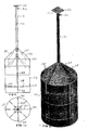
- Figure-1 shows the general views of the logic of floating and submerging the ball and forming the fixed platform.
- Figure-2 shows the general views of the logic of floating and submerging of the handled bucket and forming the fixed platform.
- Figure-3 shows the general views of the logic of floating and submerging of the glass-shaped steel float with an open bottom side and forming the fixed platform.
- Figure-4 shows the general views of the logic of floating and submerging of the concrete float with an open bottom side and forming the fixed platform.
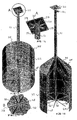
- Figure-5 is the view of the bucket as it is submerged in glass jar by means of weight.
- Figure-6 is the cut off view of the concrete float with an open bottom side.
- Figure-7 is the view of balancing the concrete float with an open bottom side by means of four weights.
- Figure-8 is the view of balancing the concrete float with an open bottom side by means of four weights and balancing the same by means of cross connections Figure-9 is the front sectional view of the steel float with an open bottom side.
- Figure-10 is the top view of the steel float with an open bottom side.
- Figure-11 is the three-dimensional perspective view of the steel float with an open bottom side.
- Figure-12 is the bottom perspective view of the steel float with an open bottom side.
- Figure-13 is the detailed view of the rope connection point of the steel float with an open bottom side
- Figure-14 is the detailed view of the connection with the concrete platform of the steel float with an open bottom side
- Figure-15 is the detailed view of the inside of the steel float with an open bottom side
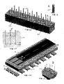
- Figure-16 is the front sectional view of the concrete floats with an open bottom side
- Figure-17 is the side sectional view of the concrete floats with an open bottom side
- Figure-18 is the detail of the columns above water of the concrete floats with an open bottom side
- Figure-19 is the perspective assembly view of the concrete floats with an open bottom side.
- Figure-20 is the perspective view of the part of the platform above water.
- Figure-21 is the perspective view of the formation of the concrete float with an open bottom side and the platform.
- Figure-22 is the detailed view of the lower connection of the concrete floats with an open bottom side.
- Figure-23 is the assembly view of the concrete floats with an open bottom side, when forming a platform.
- Figure-24 is the detailed view of the columns of the concrete floats with an open bottom side.
- Figure-25 is the side sectional and water level view of the concrete floats with an open bottom side.
- Figure-26 is the three-dimensional view of a runway formed.
- Figure-27 is the detailed view of the concrete weight submerging the floats.
- Figure-28 is the side sectional view of the float platform with an open bottom side and the view of the rope crossings.
- Figure-29 is the front sectional view of the float platform with an open bottom side and the view of the rope crossings.
- Figure-30 is the detailed view of the rope crossing connection.
- Figure-31 is the side sectional view of the platform where the invention is applied on an uneven water floor.
- Figure-32 is the perspective view of the assembly of the steel floats with an open bottom side with the platform.
- Figure-33 is the view of the water level of the steel float platform with an open bottom side.
- Figure-34 is the perspective view of the assembly of the runway completed with steel floats with an open bottom side.
- Figure-35 is the detailed view of the concrete weight submerging the steel floats with an open bottom side.
- In order to make more readily understandable the logic behind our invention which relates to the fixed structure techniques such as any kind of house, garden, road, airport, car park, children's park and holiday village built on water in the seas, lakes and rivers, let us place a plastic ball (1) having the size of a soccer ball (1) and filled with air (12) inside a netting (2). Assume we tie a rope (3) with suitable length to the handle of the netting (2), connect a weight (4) to submerge the ball (1) in water (10), and thus submerge the ball (1). As the ball (1) will want to get out of water (10) vertically, it will tighten the rope (3) tied to the netting (2) by a force corresponding to the buoyancy. We can adjust how much the ball (1) should submerge from the water level, by means of the length of the rope (3). In this simple experiment, the static stability of the weight (4) dropped onto the floor will be carried over to the ball (1) by means of the non-flexible rope (3) and the netting (2). The ball (1) must be sufficiently below the water surface (5) so that it will not be affected by the waves (11) and thus the waves (11) may easily pass over it. Let us broaden the scope of this idea. Assume we take 32 pieces of plastic balls (1) with a diameter of 25 cm. and filled with air (12). We place these one by one in 32 nettings (2) and submerge the same in the pool (4) with a depth of 2 m. by means of weights (4). We adjust the length of the ropes (3) such that all the balls (1) will be submerged at a depth of 30 cm. from the water surface (5). We arrange the weights (4) submerging the balls (1) in a suitable manner at the bottom of the pool (9) so that the balls (1) that want to come out of water will be positioned within a pattern having 4 rows of balls in width and 8 rows of balls in length. Since all the balls (1) stretch the ropes (3) in vertical direction due to buoyancy, the alignment of the weights (4) will be observed also in the balls (1). As a result, a ball (1) alignment will be obtained at about 30 cm. from the water (10) surface with a table-like shape (8) having one edge about 1 m. and the other about 2 m. Let us place a plastic table (8) having the width and length of about 1m. and 2 m., respectively, sufficiently sized to cover all the balls (1) on the balls (1) in an inverted manner so that its legs (6) extend out of water (10). And we place a 1m. wide and 2 m. long thick chipboard platform (7) on four legs of (6) of the table (8) extending out of water (10). It will be surprisingly observed that the stability and the strength of the floor of the pool (9) are exactly carried over to the chipboard platform (7), even when several children climb up the said chipboard platform (7). With a rough calculation, 32 balls (1) with 25 cm. diameter and the buoyancy of about 4 kg will produce a total buoyancy of approximately 128 kg. Another important feature of this experiment is the observation that the waves (11) in the pool (9) affect only the 4 legs (6) of the plastic table (8) that extend from 30 cm. below water (10) to the outside of the water. If the leg (6) of the table is about 60 cm. long, it means the chipboard platform (7) above the water (10) is about 30 cm. above the water (10) level. As a result, even under the conditions where the wave (11) amplitude is 50 cm. from peak to peak, the impact on the table (8) and the chipboard platform (7) will be minimal in this miniature system. The waves in the pool (9) will not pose any danger unless their height is sufficiently large to impact the table (8) 30 cm. under the water (10) and the chipboard platform (7) 30 cm. above the water (10).
- It is not difficult at all to see that the components in practice may cope with giant waves (11) even when we enlarge the features in this miniature example by 10 times according to the scale. Also, it is very natural that a drop or rise of 15 cm., for instance, in the water (10) level of the pool will not influence the system. However, the horizontal currents in water (10) and the strong winds will partially affect this system. When the system is made as monoblock and is of substantial size, the oscillations will extremely slow down due to the decrease in the frequency of resonance. To provide crosswise ropes (26) in the connections of ropes (3) with the weights (4) on the floor will provide substantial solutions in order to minimize said oscillations. Now referring to Figure-2, let us invert an ordinary handled (16) bucket (15) in a way to avoid the escape of the air (12) inside it, tie the rope (3) to its handle (16) and submerge the same to a depth of 30 cm. from the water level in the pool (9) by means of the weight (4). It will be observed that the bucket (15) will try to come out of water (10) and tighten the rope (3). The weight (4) must be greater than the buoyancy of the bucket (15).
- This simple balanced system reflects the principle of the floats (23) and steel floats (22) filled with air (12) according to the invention. Let us seat an inverted table (8) on an appropriate number of inverted and submerged buckets (15), as shown in Figure-2. Likewise, let us place the chipboard platform (7) with a suitable size on the legs of the table (8) extending out of water. Thus, a system which is not affected by the waves (11) and the variations in the water (10) level is formed. This experiment gives the same conditions and results for the glass shaped hollow steel floats (22) (see Figure-3). The system will be observed to be influenced by the waves (11) on the water surface (5) only to a negligible extent. Referring to Figure-4, the concrete float (23) with an open bottom side will be seen to provide the same function, when used in place of the concrete pontoon closed on all sides and filled with foam. In the buoyancy calculations, it must be taken into account that the water (10) will fill the gap of air compressed by the water pressure and reduced slightly in volume. There are four different examples of the floating systems. As the example of floating system, the platform with balls (17), the platform with bucket (18), the platform with steel floats with an open bottom side (19) and the concrete platform filled with air with an open bottom side (25) are shown respectively in Figure-1, Figure-2, Figure-3 and Figure-4. As will be evident from the figures, the floating systems are open to and unprotected against any effect of the waves, currents, storms and water level variations. They may be partially protected against some of said impacts by way of connecting to the floor or the shore by means of ropes.
- In Figure-5, a stand (28) is placed on the inverted bucket (15) which submerged by means of weight (4) in the water (10) filled into the glass jar (29). Playing cards (27) are arranged symbolically on the stand (28) in such a way that they are very easy to collapse. It was observed that the playing cards (27) do not collapse even when the water (10) is caused to break into waves.
- In Figure-6, the three-dimensional sectional view of the concrete float (23) filled with air (12) and having an open bottom side. A plurality of these floats may be produced in combination, by means of the moulds. In this way, very high buoyancies are obtained. In Figure-7, we see the method for seating on the floor by means of four weights (4) and four ropes (3), while Figure-8 shows the method of fixation using the cross connections (26). In Figure-9, the column pipes (21) are observed to be reinforced by 8 ribs (30) for the connection thereof to the float (22), in the sectional view of the hollow steel float (22) with an open bottom side. Said ribs (30) are taken into the float (22) for hydrodynamic reasons, in order to reduce the overall surface of the float (22). In the top sectional view of the steel float (22) with an open bottom side in Figure-10, 4 pieces of float connecting ratchets (35) at an angle of 90 degrees each, 8 pieces of centering rod (38) and 8 pieces of ribs (30) can be seen. In Figure-11, the sheet iron plates (48) with a cross-section thickening from the bottom are used in manufacturing the steel float (22) with an open bottom side. The reason for this is that the pressure of the air confined in the floats (22) with bottom side open is constant at every point on the interior surfaces. As a result, the external water pressure reduces in the upward direction along the column (21), while the air pressure is equal to the pressure at the bottom water level of the float (22); hence the internal tensile forces increase. The conical cover (36) thickness must be made maximum so that it can meet the pressure forces and transfer the buoyancies of the float to the platform (7) by means of single column (21) by centering the buoyancies of the float.
- The column (21) centered and reinforced by 8 ribs (30) on the inside must be made of preferably seamless pipe with suitable diameter and high wall thickness. Inside this column (21), the rope (3) and the pipe (33) with suitable diameter serving to convey the water (10) and air (12) and extending up to the lower sections of the column pass. Said pipe (33) open to water on the lower end and connected to the rope length adjustment outlet (34) close to the platform (7) on the upper end makes up for the reduced amount of air in the float (22) by means of pressurized air (12), when necessary. It must be of a sufficiently large inner diameter so that it will not hinder the re-adjustment of the rope (3) length when needed. Moreover, the warm floor water sucked through this pipe (33) must be of such an amount to allow the circulation thereof from the platform (7) serpentine system by means of the circulation motors. In this way, icing is prevented on the platform surface which is open on the bottom and the top to the weather conditions.
- Figure-12 shows the positioning of the connection ratchets (35) and the rope connection handle (40) in the steel float (22) with the bottom side open, while Figure-13 shows their details. In the detailed view in Figure-14, the flange (20) connecting the column (21) with the platform (7) and 4 bolt holes (37) which enable securing said flange by means of bolts to the platform (7) may be seen. 8 reinforcing ribs (30) are welded to the point where the column is connected to the flange plate (20). In Figure-15 showing the three-dimensional partial section view of the steel float (22) with bottom side open, the way in which the steel guide pipe (33) at the center of the float (22) is centered in the regions close to the bottom by means of 8 centering rods (38) may be seen. Said centering centers the suspension force from the floor by means of the rope (3) and is also important in vertical balancing of the float (22).
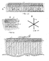
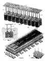
- In Figure-16, 6 pieces of the concrete floats (23) with bottom side open are shown in cross-section in the form of a single unit, where it may also be seen that the number of cells of the float (23) may be increased and enlarged to the extent allowed by the size of the big moulds. As will be evident from the side view in Figure-17, it is even possible to construct long motorways by bringing together and connecting longitudinally as in a pie slice. Figure-18 shows the details of the rope pipe (33) along with the details of the rope length adjustment outlet (34), which also enables the air and water discharge, where the ironstones (42) of the column (21) with semi-circular cross section cast in combined mould with the concrete float with round sides facing one another may also be seen.
- In Figure-19, sectional production phases of the three-dimensional concrete floats (23) with bottom side open, from the cell formation in Figure-21 to the formation of the column and the platform. The details of the serpentine pipe (47) laid inside the platform (7) and the monoblock concrete float (23) planar on two sides comprising 10 cells may be seen. In Figure-20, it may be seen that the cross sectional thickness of the platform (7), lower part of which is shown, increases towards the center of the column and it is weakest in the middle of the two columns (21). In Figure-22, a pipe is passed inside the column (21) with a semi-circular cross section, which pipe connects to the float (23) by means of the column (21) starting under the concrete platform (7), passes through the side screen wall of the float (23) and extends up to the concrete projecting handles (43) connecting the floats (23) with the weights (4). The upper end of this pipe starts immediately below the column ironstones (42) and extends up to under the concrete projecting handles (43) connecting the weight (4). Said pipe (33) takes on 3 functions, namely making up for the amount of air lost from the float, sucking from the bottom the serpentine (47) water and being the rope length adjustment outlet (34).
- Figure-23 shows how the concrete float (23) blocks in the form of 10-cell monoblock are brought side by side, are connected to one another by way of clamping from the columns (21) and how the monoblock platform (7) may be easily cast on the water using wooden moulds from below, as in adding a storey in a construction. Figure-24 shows in detail how two columns (21) with semi-circular cross section of two concrete floats (23) brought side by side are converted to a cylindrical (45) column (21). Reference to the horizontal sectional view in Figure-25, it is possible to understand at what depth from the water level (5) the monoblock concrete floats (23) with bottom side open brought side by side will be submerged. When we submerge the floats (23) so that they will sink down up to exactly half of the columns (21), the extent to which they are influenced by the waves will be minimized. In Figure-26, a three-dimensional airplane runway section is formed by connecting the weights (4) with the float (23) units by means of the ropes (3), connecting the float (23) units to one another by means of clamps from the columns (21), adjusting the rope (3) lengths, aligning all the float (23) units to the same level and completing the cast of the monoblock concrete platform (7) over the column ironstones (42) by means of the moulds. In Figure-27, the weight connecting handles (41) are seen in a detailed view of the rope (3) connections of the weights (4). Figure-28 illustrates the sectional view of the completed runway and the water level (5). As will be understood from the section, the concrete floats (23) are submerged and secured in the water (10) up to the half length of the columns (21), by means of the ropes (3) connected with the weights (4) arranged on water (10) floor. Here an application is seen where the oscillations are minimized in every direction by occasionally employing transversal and longitudinal crosswise ropes (26).
- Figure-29 illustrates the transversal crosswise rope connection (26), weight (4), concrete float (23), column (21) and platform (7) in transverse cross section, as well as the water level. Figure-30 includes the detailed view showing the necessity to secure to one another the crosswise rope connections (26). Figure-31 is a cross sectional view illustrating how the rope (3) lengths will be regulated in cases where the water (10) floor is not smooth and how the runway formed by the concrete floats (23) will be positioned in a flat manner. As seen in the figures, the floats (23) are always adjusted so that they are submerged in water (20) by half, with the steel floats (22) being included. The distances from the wave peaks and the wave pits to the platform (7) and the concrete float (23) surface must always be equal.
- In Figure-32, 18-cell independent steel floats (22) with bottom side open are converted to monoblock by bringing side by side the ratchets thereof and clamping the same. In order to mount the monoblock platform on the columns extending from the central axes of the steel floats with bottom side open, the parts (20) connecting the columns to the platform are used. Said connection is provided by passing the bolts through the bolt hole (37).
- Reference to the horizontal sectional view in Figure-33, it is possible to understand at what depth from the water (10) level (5) the monoblock steel floats (22) with bottom side open brought side by side will be submerged. When we submerge the steel floats (22) so that they will sink down up to exactly half of the columns (21), the extent to which they are influenced by the waves will be minimized.
- In Figure-34, a three-dimensional airplane runway section is formed by connecting the weights (4) with the float (22) units by means of the ropes (3), clamping the float (22) units to one another by means of ratchets (35) to form steel floats (22) in the form of monoblock, adjusting the rope (3) lengths, aligning all the float (22) units to the same level and completing the cast of the monoblock concrete platform (7) over the column connecting pieces (20) by means of the moulds.
- In the detailed view of the connections between the weights (4) and the ropes (3) shown in Figure-35, the weight connecting handles (41) may be seen.
- The present invention may be used to construct roads, bridges, car parks, airports, houses, amusement centers, business centers, social facilities, sport complexes, concert centers, earthquake houses, agricultural fields and the road connections between the islands, between the islands and the shores and between the shores and in all the fixed structures on the platforms, owing to the formation of the platforms suitable for any fixed structure on the water having high stability even in deep waters.
Claims (14)
- A fixed platform assembly which enables to locate on water any fixed structure such as the house, garden,road, airport, car park, children's park and holiday village in the seas, lakes and rivers, the fixed platform assembly comprising:- a platform (7),- open bottomed air-filled floats (22),- weights (4),- connecting ropes (3) that connected one end of the weights (4) and the open bottomed air-filled floats (22);whereby:- the open bottomed air-filled floats (22) are made of concrete or steel and are submerged up to a safe zone of three to five meters below the surface of water (10), the open bottomed air-filled floats (22) create buoyant energy and because of that try to come to the water surface (5) to maintain the platform (7) always at the same level owing to the tightness of the plurality of the connecting ropes (3) which are connected to the open bottomed air-filled floats (22), said platform (7) being prevented from being drifted by the violent storms and huge waves and the currents in the sea, the open bottomed air-filled floats (22) are preferably made of steel and are preferably galvanized or painted and produce buoyancy for carrying the platform (7),- the connecting ropes (3) serve to maintain the open bottomed air-filled floats (22) at a constant distance from the floor and in a submerged state;the fixed platform assembly being characterised in that:- each of the open bottomed air-filled floats (22) has:- a bottom side opening with air (12) entrapped inside,- at least a rib (30) strengthening column,- a pipe (33) guiding the connecting rope (3) connected with the weight (4),- an hollow carrier column (21) connected with the flags (30),- a centering rod (38) close to the section where the bottom side is open,- a crosswise rope connection handle (40),- a plurality of ratchets (35) connecting the floats (22) to one another,- a connecting flange (20) for connection with the platform (7) and a rope length adjustment outlet (34) under the connection flange (20);- said floats (22) are conical on their upper side and open on their bottom part, said floats (22) have sheet thickness decreasing downwards and being resistant to corrosion and oxidation, said floats (22) have a modular structure capable of being joined to one another when brought side by side;- the plurality of hollow carrier columns (21) of said floats connect said floats (22) with the platform (7), and the plurality of connecting flanges (20) connect said columns (21) with the platform (7).
- The fixed platform assembly according to claim- 1 characterized in that it is preferably made of concrete and it comprises the weight (4) formed by filled-in block concrete resistant to sea water with reinforced concrete having iron cage placed therein, which weight has an ability to be firmly established on floor and thereby has feet trusted into the floor to prevent the platform from moving around and a plurality of handles (41) through which the steel ropes (3) may be connected to upper part thereof.
- The fixed platform assembly according to claim- 1 characterized in that it comprises the connecting ropes (3) coated against oxidation and corrosion, preferably by galvanization, which have high tolerance and an as small as possible bending margin, have one end thereof secured by means of counter clamps once said ends are connected to the handle (41) located on weight, have an other end entering through the air pipe (33) on central axis of the open bottomed air-filled float (22) and exiting at a point close to below the platform, and length of which may be adjusted as desired and affixed by means of the clamps.
- The fixed platform assembly according to claim- 1 characterized in that it comprises a flat connection to meet by means of weights (4) vertical buoyancies that must go from the pipe (33) in the central axis to the below platform (7) in order for length of the rope (3) connected with the weight (4) to be able to be adjusted from above and a crosswise connection (26) to minimize the oscillations towards any horizontal direction.
- The fixed platform assembly according to claim- 1 characterized in that it comprises the open bottomed air-filled float (22) units made preferably of a reinforced concrete on unit basis, which have a cellular structure dividing an air entrapped under them, columns affixed to concrete block with a plurality of ironstones (42) left thereon to enable casting the concrete platform (7) and the handles (43) with a concrete projections in the lower parts thereof to enable the connection of the weights (4), have a mono block unit with screen a plurality of concrete walls (44) with a thickness kept as small as possible and have a modular structure capable of being joined to one another when brought side by side.
- The fixed platform assembly according to claim- 1 characterized in that it has the platform (7) with a slightly dome-shaped structure (46) between the columns (21), whereby sections where the platform (7) connects with the column ironstones (42) are thick and the platform (7) cross sections become thinner with increasing distance from the columns (21).
- The fixed platform assembly according to claim- 1 characterized in that it comprises the ribs (30) which enable fixing the hollow column (21) and the float (22) by way of reinforcing from inside in order to reduce the overall exterior surface of the float (22).
- The fixed platform assembly according to claim-1 characterized in that a plurality of sheet iron plates (48) having a cross section that increases starting from the bottom are used in manufacturing the open bottomed air-filled steel float (22).
- The fixed platform assembly according to claim-1 characterized in that conicity and sheet thickness of a cover (36) are made maximum in a way to meet pressure forces and to center buoyancies of the float (22) to be transferred to the platform (7) by means of single column (21).
- The fixed platform assembly according to claim-1 characterized in that the column (21) centered and reinforced from inside by means of the rib (30) is preferably made of a single piece of seamless pipe with large wall thickness and suitable diameter.
- The fixed platform assembly according to claim- 1 characterized in that it comprises a connecting projection (43) which extends from point that steel pipe (33) where the connection rope (3) and air pass is connected with the float (22, 23) up to a lowermost end of the float (22, 23).
- The fixed platform assembly according to claim- 1 characterized in that the concrete floats (23) and steel floats (22) are of modular structure in order to be able to individually lower them towards bottom of water and to mount new floats in place of the replaced ones.
- The fixed platform assembly according to claim- 1 characterized in that it comprises a heating serpentine (47) system preventing the icing, where warm water at the bottom of the sea coming from the steel rope (3) and air pipe(33) will be passed, laid at suitable intervals while the platform (7) concrete is being cast.
- The fixed platform assembly according to claim- 1 characterized in that the float (22-23) comprises an air filling system for air cells, which forces pressurized air from the pipe inside column (21) when an amount of air entrapped in floats (22-23) decreases, in order to increase said amount to a desired level.
Applications Claiming Priority (2)
| Application Number | Priority Date | Filing Date | Title |
|---|---|---|---|
| TR2005/05181A TR200505181A2 (en) | 2005-12-23 | 2005-12-23 | Stationary structuring platform above water |
| PCT/TR2006/000072 WO2007073359A2 (en) | 2005-12-23 | 2006-12-20 | Fixed structure platform on water |
Publications (2)
| Publication Number | Publication Date |
|---|---|
| EP1966037A2 EP1966037A2 (en) | 2008-09-10 |
| EP1966037B1 true EP1966037B1 (en) | 2011-02-16 |
Family
ID=38189108
Family Applications (1)
| Application Number | Title | Priority Date | Filing Date |
|---|---|---|---|
| EP06836010A Not-in-force EP1966037B1 (en) | 2005-12-23 | 2006-12-20 | Fixed structure platform on water |
Country Status (13)
| Country | Link |
|---|---|
| US (1) | US20090217856A1 (en) |
| EP (1) | EP1966037B1 (en) |
| KR (1) | KR20080090456A (en) |
| CN (1) | CN101389527A (en) |
| AT (1) | ATE498543T1 (en) |
| AU (1) | AU2006327288A1 (en) |
| CA (1) | CA2634916A1 (en) |
| DE (1) | DE602006020175D1 (en) |
| EA (1) | EA014336B1 (en) |
| IL (1) | IL192396A0 (en) |
| MX (1) | MX2008008243A (en) |
| TR (1) | TR200505181A2 (en) |
| WO (1) | WO2007073359A2 (en) |
Cited By (2)
| Publication number | Priority date | Publication date | Assignee | Title |
|---|---|---|---|---|
| WO2015133661A1 (en) * | 2014-03-04 | 2015-09-11 | 울산대학교 산학협력단 | Floating maritime platform provided with airport |
| DE102018124072A1 (en) * | 2018-09-28 | 2020-04-02 | GICON-Großmann Ingenieur Consult GmbH | Floating foundation of a bridge pier |
Families Citing this family (17)
| Publication number | Priority date | Publication date | Assignee | Title |
|---|---|---|---|---|
| SE532415C2 (en) * | 2008-05-14 | 2010-01-12 | Aquavilla Ab | Device for preventing ice formation on a surface layer |
| CN101844605B (en) * | 2010-05-31 | 2011-07-13 | 南通中远船务工程有限公司 | Method of manufacturing technology of ultra-deep large cylinder-shaped drilling platform main hull |
| JP5838439B2 (en) * | 2011-03-25 | 2016-01-06 | 五洋建設株式会社 | Installation method and removal method and structure of floating offshore wind turbine generator |
| CN102862655B (en) * | 2012-09-24 | 2015-02-04 | 李锦新 | Structure member standing in water and capable of stably loading |
| CN103129716A (en) * | 2012-11-09 | 2013-06-05 | 温秀生 | Sea plane take-off, landing and accessory device |
| CN102943432A (en) * | 2012-11-28 | 2013-02-27 | 杨石红 | Sea floating bridge |
| CN104975590B (en) * | 2014-04-04 | 2019-02-22 | 广东海上城建控股发展有限公司 | The vertical assembling technique waterborne of prestressed concrete fixed platform waterborne |
| CN104260843B (en) * | 2014-10-30 | 2016-08-24 | 孙本新 | The floating on water surface airport that can travel |
| CN104843151A (en) * | 2015-04-06 | 2015-08-19 | 陈佳宇 | Offshore power generation platform formed by combining floating body units and installation method of offshore power generation platform |
| CN104802952B (en) * | 2015-04-06 | 2017-05-03 | 陈佳宇 | Soft floating body unit, pipeline pole based on floating body unit, generating station and air charging model |
| CN104743080A (en) * | 2015-04-06 | 2015-07-01 | 陈佳宇 | Floating unit and waterborne pipeline supporting system consisting of same |
| CN104802949A (en) * | 2015-04-06 | 2015-07-29 | 陈佳宇 | Float unit and combined water platform |
| CN107280771A (en) * | 2016-03-31 | 2017-10-24 | 北京中医药大学 | Simulate the life entity experimental provision under the length boat state of ocean |
| CN106592356B (en) * | 2016-11-03 | 2018-12-18 | 胡元运 | A kind of floating road |
| CN106544942B (en) * | 2016-11-03 | 2018-08-17 | 东莞市联洲知识产权运营管理有限公司 | A kind of flood road |
| KR101886815B1 (en) * | 2017-05-30 | 2018-08-08 | 이현용 | Semi-Buoyancy Assisted Fixed Marine AirPort |
| CN111645819B (en) * | 2020-06-15 | 2021-06-29 | 黄芳 | Stably suspended offshore floating platform |
Family Cites Families (6)
| Publication number | Priority date | Publication date | Assignee | Title |
|---|---|---|---|---|
| US1511153A (en) * | 1922-11-07 | 1924-10-07 | Edward R Armstrong | Sea station |
| US1670524A (en) * | 1927-08-18 | 1928-05-22 | Gustave M Sachs | Sea air port |
| US1847551A (en) * | 1930-04-14 | 1932-03-01 | Internat Aerdrome And Seadrome | Seadrome or airplane landing |
| US2399611A (en) * | 1942-05-14 | 1946-05-07 | Edward R Armstrong | Submersible seadrome |
| US3702105A (en) * | 1971-03-17 | 1972-11-07 | Lummus Co | Deep water drilling rig |
| RU2174930C2 (en) * | 1999-07-07 | 2001-10-20 | Кузьмин Александр Сергеевич | Floating semisubmersible ice-resistant platform |
-
2005
- 2005-12-23 TR TR2005/05181A patent/TR200505181A2/en unknown
-
2006
- 2006-12-20 US US12/158,981 patent/US20090217856A1/en not_active Abandoned
- 2006-12-20 CN CNA2006800533550A patent/CN101389527A/en active Pending
- 2006-12-20 DE DE602006020175T patent/DE602006020175D1/en active Active
- 2006-12-20 AT AT06836010T patent/ATE498543T1/en not_active IP Right Cessation
- 2006-12-20 EA EA200801503A patent/EA014336B1/en not_active IP Right Cessation
- 2006-12-20 MX MX2008008243A patent/MX2008008243A/en not_active Application Discontinuation
- 2006-12-20 CA CA002634916A patent/CA2634916A1/en not_active Abandoned
- 2006-12-20 KR KR1020087018179A patent/KR20080090456A/en not_active Application Discontinuation
- 2006-12-20 EP EP06836010A patent/EP1966037B1/en not_active Not-in-force
- 2006-12-20 AU AU2006327288A patent/AU2006327288A1/en not_active Abandoned
- 2006-12-20 WO PCT/TR2006/000072 patent/WO2007073359A2/en active Application Filing
-
2008
- 2008-06-23 IL IL192396A patent/IL192396A0/en unknown
Cited By (3)
| Publication number | Priority date | Publication date | Assignee | Title |
|---|---|---|---|---|
| WO2015133661A1 (en) * | 2014-03-04 | 2015-09-11 | 울산대학교 산학협력단 | Floating maritime platform provided with airport |
| DE102018124072A1 (en) * | 2018-09-28 | 2020-04-02 | GICON-Großmann Ingenieur Consult GmbH | Floating foundation of a bridge pier |
| DE102018124072B4 (en) | 2018-09-28 | 2023-03-23 | GICON-Großmann Ingenieur Consult GmbH | Floating foundation of a bridge pier |
Also Published As
| Publication number | Publication date |
|---|---|
| KR20080090456A (en) | 2008-10-08 |
| AU2006327288A1 (en) | 2007-06-28 |
| DE602006020175D1 (en) | 2011-03-31 |
| EA200801503A1 (en) | 2009-04-28 |
| EA014336B1 (en) | 2010-10-29 |
| WO2007073359A3 (en) | 2008-07-17 |
| ATE498543T1 (en) | 2011-03-15 |
| CA2634916A1 (en) | 2007-06-28 |
| WO2007073359A2 (en) | 2007-06-28 |
| EP1966037A2 (en) | 2008-09-10 |
| MX2008008243A (en) | 2008-11-14 |
| TR200505181A2 (en) | 2007-07-23 |
| CN101389527A (en) | 2009-03-18 |
| IL192396A0 (en) | 2009-08-03 |
| US20090217856A1 (en) | 2009-09-03 |
Similar Documents
| Publication | Publication Date | Title |
|---|---|---|
| EP1966037B1 (en) | Fixed structure platform on water | |
| US11448193B2 (en) | Self-aligning to wind facing floating platform supporting multi-wind turbines and solar for wind and solar power generation and the construction method thereon | |
| US9915047B2 (en) | Energy dissipator | |
| US20100218712A1 (en) | Floating Latticework | |
| ES2952964T3 (en) | Maritime structure for the foundation of buildings and its installation method | |
| CN103010415A (en) | Prestressed concrete floating platform for supporting offshore wind turbine and ocean power generator | |
| EP3626889B1 (en) | Sea tunnel | |
| JP2005521588A (en) | Floating structure | |
| CN113619742B (en) | Hybrid floating offshore wind turbine platform and design and construction method of composite material side column thereof | |
| US3958426A (en) | Offshore harbor tank and installation | |
| WO2016042173A1 (en) | Gravity foundation for the installation of offshore wind turbines and meteorological towers | |
| CN201459753U (en) | Base for offshore lighthouse | |
| WO2020136288A1 (en) | Floating platform for high-power wind turbines | |
| KR100282982B1 (en) | Revetment construction method using sofa block | |
| KR101112751B1 (en) | The house built on stilts over the water where the balanced maintenance means is had | |
| CN215794349U (en) | Hydrophilic platform capable of changing amplitude along with water level | |
| Koekoek | Connecting modular floating structures: a general survey and structural design of a modular floating pavilion | |
| RU2699198C1 (en) | Floating ferry with floating module and floating support with pylon | |
| Timmers | Technical feasibility of a demountable floating body for a demountable stadium | |
| Howard et al. | Structural design of deep water pontoon mooring anchors | |
| JPH03140514A (en) | Ground floating on water in ultra calmness | |
| CN117552308A (en) | Pipeline type bridge | |
| CN114775527A (en) | Ultra-deep dynamic water area revetment sinking and paving plate | |
| JPH02200595A (en) | Water park | |
| Mestemaker | Floating Structures: Floating Centre for the Performing Arts in the Harbour of Scheveningen |
Legal Events
| Date | Code | Title | Description |
|---|---|---|---|
| PUAI | Public reference made under article 153(3) epc to a published international application that has entered the european phase |
Free format text: ORIGINAL CODE: 0009012 |
|
| 17P | Request for examination filed |
Effective date: 20080625 |
|
| AK | Designated contracting states |
Kind code of ref document: A2 Designated state(s): AT BE BG CH CY CZ DE DK EE ES FI FR GB GR HU IE IS IT LI LT LU LV MC NL PL PT RO SE SI SK TR |
|
| AX | Request for extension of the european patent |
Extension state: AL BA HR MK RS |
|
| 17Q | First examination report despatched |
Effective date: 20081112 |
|
| GRAP | Despatch of communication of intention to grant a patent |
Free format text: ORIGINAL CODE: EPIDOSNIGR1 |
|
| DAX | Request for extension of the european patent (deleted) | ||
| GRAS | Grant fee paid |
Free format text: ORIGINAL CODE: EPIDOSNIGR3 |
|
| GRAA | (expected) grant |
Free format text: ORIGINAL CODE: 0009210 |
|
| AK | Designated contracting states |
Kind code of ref document: B1 Designated state(s): AT BE BG CH CY CZ DE DK EE ES FI FR GB GR HU IE IS IT LI LT LU LV MC NL PL PT RO SE SI SK TR |
|
| REG | Reference to a national code |
Ref country code: GB Ref legal event code: FG4D |
|
| REG | Reference to a national code |
Ref country code: CH Ref legal event code: EP |
|
| REG | Reference to a national code |
Ref country code: IE Ref legal event code: FG4D |
|
| REF | Corresponds to: |
Ref document number: 602006020175 Country of ref document: DE Date of ref document: 20110331 Kind code of ref document: P |
|
| REG | Reference to a national code |
Ref country code: DE Ref legal event code: R096 Ref document number: 602006020175 Country of ref document: DE Effective date: 20110331 |
|
| REG | Reference to a national code |
Ref country code: NL Ref legal event code: VDEP Effective date: 20110216 |
|
| LTIE | Lt: invalidation of european patent or patent extension |
Effective date: 20110216 |
|
| PG25 | Lapsed in a contracting state [announced via postgrant information from national office to epo] |
Ref country code: LT Free format text: LAPSE BECAUSE OF FAILURE TO SUBMIT A TRANSLATION OF THE DESCRIPTION OR TO PAY THE FEE WITHIN THE PRESCRIBED TIME-LIMIT Effective date: 20110216 Ref country code: LV Free format text: LAPSE BECAUSE OF FAILURE TO SUBMIT A TRANSLATION OF THE DESCRIPTION OR TO PAY THE FEE WITHIN THE PRESCRIBED TIME-LIMIT Effective date: 20110216 Ref country code: PT Free format text: LAPSE BECAUSE OF FAILURE TO SUBMIT A TRANSLATION OF THE DESCRIPTION OR TO PAY THE FEE WITHIN THE PRESCRIBED TIME-LIMIT Effective date: 20110616 Ref country code: ES Free format text: LAPSE BECAUSE OF FAILURE TO SUBMIT A TRANSLATION OF THE DESCRIPTION OR TO PAY THE FEE WITHIN THE PRESCRIBED TIME-LIMIT Effective date: 20110527 Ref country code: SE Free format text: LAPSE BECAUSE OF FAILURE TO SUBMIT A TRANSLATION OF THE DESCRIPTION OR TO PAY THE FEE WITHIN THE PRESCRIBED TIME-LIMIT Effective date: 20110216 Ref country code: GR Free format text: LAPSE BECAUSE OF FAILURE TO SUBMIT A TRANSLATION OF THE DESCRIPTION OR TO PAY THE FEE WITHIN THE PRESCRIBED TIME-LIMIT Effective date: 20110517 |
|
| PG25 | Lapsed in a contracting state [announced via postgrant information from national office to epo] |
Ref country code: PL Free format text: LAPSE BECAUSE OF FAILURE TO SUBMIT A TRANSLATION OF THE DESCRIPTION OR TO PAY THE FEE WITHIN THE PRESCRIBED TIME-LIMIT Effective date: 20110216 Ref country code: AT Free format text: LAPSE BECAUSE OF FAILURE TO SUBMIT A TRANSLATION OF THE DESCRIPTION OR TO PAY THE FEE WITHIN THE PRESCRIBED TIME-LIMIT Effective date: 20110216 Ref country code: BE Free format text: LAPSE BECAUSE OF FAILURE TO SUBMIT A TRANSLATION OF THE DESCRIPTION OR TO PAY THE FEE WITHIN THE PRESCRIBED TIME-LIMIT Effective date: 20110216 Ref country code: FI Free format text: LAPSE BECAUSE OF FAILURE TO SUBMIT A TRANSLATION OF THE DESCRIPTION OR TO PAY THE FEE WITHIN THE PRESCRIBED TIME-LIMIT Effective date: 20110216 Ref country code: NL Free format text: LAPSE BECAUSE OF FAILURE TO SUBMIT A TRANSLATION OF THE DESCRIPTION OR TO PAY THE FEE WITHIN THE PRESCRIBED TIME-LIMIT Effective date: 20110216 Ref country code: SI Free format text: LAPSE BECAUSE OF FAILURE TO SUBMIT A TRANSLATION OF THE DESCRIPTION OR TO PAY THE FEE WITHIN THE PRESCRIBED TIME-LIMIT Effective date: 20110216 Ref country code: CY Free format text: LAPSE BECAUSE OF FAILURE TO SUBMIT A TRANSLATION OF THE DESCRIPTION OR TO PAY THE FEE WITHIN THE PRESCRIBED TIME-LIMIT Effective date: 20110216 Ref country code: BG Free format text: LAPSE BECAUSE OF FAILURE TO SUBMIT A TRANSLATION OF THE DESCRIPTION OR TO PAY THE FEE WITHIN THE PRESCRIBED TIME-LIMIT Effective date: 20110516 |
|
| PG25 | Lapsed in a contracting state [announced via postgrant information from national office to epo] |
Ref country code: EE Free format text: LAPSE BECAUSE OF FAILURE TO SUBMIT A TRANSLATION OF THE DESCRIPTION OR TO PAY THE FEE WITHIN THE PRESCRIBED TIME-LIMIT Effective date: 20110216 Ref country code: DK Free format text: LAPSE BECAUSE OF FAILURE TO SUBMIT A TRANSLATION OF THE DESCRIPTION OR TO PAY THE FEE WITHIN THE PRESCRIBED TIME-LIMIT Effective date: 20110216 |
|
| PG25 | Lapsed in a contracting state [announced via postgrant information from national office to epo] |
Ref country code: RO Free format text: LAPSE BECAUSE OF FAILURE TO SUBMIT A TRANSLATION OF THE DESCRIPTION OR TO PAY THE FEE WITHIN THE PRESCRIBED TIME-LIMIT Effective date: 20110216 Ref country code: SK Free format text: LAPSE BECAUSE OF FAILURE TO SUBMIT A TRANSLATION OF THE DESCRIPTION OR TO PAY THE FEE WITHIN THE PRESCRIBED TIME-LIMIT Effective date: 20110216 Ref country code: CZ Free format text: LAPSE BECAUSE OF FAILURE TO SUBMIT A TRANSLATION OF THE DESCRIPTION OR TO PAY THE FEE WITHIN THE PRESCRIBED TIME-LIMIT Effective date: 20110216 |
|
| PLBE | No opposition filed within time limit |
Free format text: ORIGINAL CODE: 0009261 |
|
| STAA | Information on the status of an ep patent application or granted ep patent |
Free format text: STATUS: NO OPPOSITION FILED WITHIN TIME LIMIT |
|
| 26N | No opposition filed |
Effective date: 20111117 |
|
| REG | Reference to a national code |
Ref country code: DE Ref legal event code: R097 Ref document number: 602006020175 Country of ref document: DE Effective date: 20111117 |
|
| PG25 | Lapsed in a contracting state [announced via postgrant information from national office to epo] |
Ref country code: IT Free format text: LAPSE BECAUSE OF FAILURE TO SUBMIT A TRANSLATION OF THE DESCRIPTION OR TO PAY THE FEE WITHIN THE PRESCRIBED TIME-LIMIT Effective date: 20110216 |
|
| PG25 | Lapsed in a contracting state [announced via postgrant information from national office to epo] |
Ref country code: MC Free format text: LAPSE BECAUSE OF NON-PAYMENT OF DUE FEES Effective date: 20111231 |
|
| REG | Reference to a national code |
Ref country code: CH Ref legal event code: PL |
|
| GBPC | Gb: european patent ceased through non-payment of renewal fee |
Effective date: 20111220 |
|
| REG | Reference to a national code |
Ref country code: FR Ref legal event code: ST Effective date: 20120831 |
|
| REG | Reference to a national code |
Ref country code: IE Ref legal event code: MM4A |
|
| REG | Reference to a national code |
Ref country code: DE Ref legal event code: R119 Ref document number: 602006020175 Country of ref document: DE Effective date: 20120703 |
|
| PG25 | Lapsed in a contracting state [announced via postgrant information from national office to epo] |
Ref country code: LI Free format text: LAPSE BECAUSE OF NON-PAYMENT OF DUE FEES Effective date: 20111231 Ref country code: IE Free format text: LAPSE BECAUSE OF NON-PAYMENT OF DUE FEES Effective date: 20111220 Ref country code: CH Free format text: LAPSE BECAUSE OF NON-PAYMENT OF DUE FEES Effective date: 20111231 Ref country code: GB Free format text: LAPSE BECAUSE OF NON-PAYMENT OF DUE FEES Effective date: 20111220 Ref country code: DE Free format text: LAPSE BECAUSE OF NON-PAYMENT OF DUE FEES Effective date: 20120703 |
|
| PG25 | Lapsed in a contracting state [announced via postgrant information from national office to epo] |
Ref country code: FR Free format text: LAPSE BECAUSE OF NON-PAYMENT OF DUE FEES Effective date: 20120102 |
|
| PG25 | Lapsed in a contracting state [announced via postgrant information from national office to epo] |
Ref country code: LU Free format text: LAPSE BECAUSE OF NON-PAYMENT OF DUE FEES Effective date: 20111220 |
|
| PG25 | Lapsed in a contracting state [announced via postgrant information from national office to epo] |
Ref country code: IS Free format text: LAPSE BECAUSE OF FAILURE TO SUBMIT A TRANSLATION OF THE DESCRIPTION OR TO PAY THE FEE WITHIN THE PRESCRIBED TIME-LIMIT Effective date: 20110216 |
|
| PG25 | Lapsed in a contracting state [announced via postgrant information from national office to epo] |
Ref country code: TR Free format text: LAPSE BECAUSE OF FAILURE TO SUBMIT A TRANSLATION OF THE DESCRIPTION OR TO PAY THE FEE WITHIN THE PRESCRIBED TIME-LIMIT Effective date: 20110216 |
|
| PG25 | Lapsed in a contracting state [announced via postgrant information from national office to epo] |
Ref country code: HU Free format text: LAPSE BECAUSE OF FAILURE TO SUBMIT A TRANSLATION OF THE DESCRIPTION OR TO PAY THE FEE WITHIN THE PRESCRIBED TIME-LIMIT Effective date: 20110216 |