EP1965497A1 - Distributed arithmetic coding method - Google Patents
Distributed arithmetic coding method Download PDFInfo
- Publication number
- EP1965497A1 EP1965497A1 EP07425116A EP07425116A EP1965497A1 EP 1965497 A1 EP1965497 A1 EP 1965497A1 EP 07425116 A EP07425116 A EP 07425116A EP 07425116 A EP07425116 A EP 07425116A EP 1965497 A1 EP1965497 A1 EP 1965497A1
- Authority
- EP
- European Patent Office
- Prior art keywords
- interval
- sub
- source
- intervals
- sequence
- Prior art date
- Legal status (The legal status is an assumption and is not a legal conclusion. Google has not performed a legal analysis and makes no representation as to the accuracy of the status listed.)
- Granted
Links
Images


Classifications
-
- H—ELECTRICITY
- H03—ELECTRONIC CIRCUITRY
- H03M—CODING; DECODING; CODE CONVERSION IN GENERAL
- H03M7/00—Conversion of a code where information is represented by a given sequence or number of digits to a code where the same, similar or subset of information is represented by a different sequence or number of digits
- H03M7/30—Compression; Expansion; Suppression of unnecessary data, e.g. redundancy reduction
- H03M7/40—Conversion to or from variable length codes, e.g. Shannon-Fano code, Huffman code, Morse code
- H03M7/4006—Conversion to or from arithmetic code
Definitions
- the present invention relates to a method of distributed source coding.
- the invention relates to a method to perform the coding and the decoding of communication data coming from statistically dependent sources.
- the distributed source coding considers the situation in which two or more statistically dependent data sources must be encoded by two separate encoders that are not allowed to talk each other, i.e., when the two sources are not jointly available (i.e., they are not within the same device) and therefore the communication between them would be impossible or very expensive, as in the case of a network of wireless sensors.
- each encoder has available only the data coming from one of the two sources.
- Equally appealing is the possibility of applying distributed source coding principles to situations where a single source is artificially subdivided into correlated sub-sources that are encoded separately, e.g., different frames of a video sequence. In this case the advantage is that decorrelation among the sub-sources is no longer required, thus simplifying the encoder (though at the expenses of the decoder).
- the two encoders can perform lossless compression of the two sources each by using a bit rate greater than the entropy of either source; however, this type of separate compression constitutes a loss of efficiency with respect to the use of an encoder that jointly compresses the two sources, since in this case a bit rate equal to the joint entropy of the sources could be used, which is smaller than the entropy of each source.
- the distributed source coding theory has proved that, under certain assumptions, the same result as the joint coding can be achieved by using two separate encoders, provided that the two sources are decoded by a joint decoder. It is possible to get this performing a standard encoding of one of the two sources (called “side information") at its entropy value, and an "ambiguous" encoding of the other source at a rate lower than its entropy, with no information about the first source available at the second encoder.
- a source is encoded ambiguously when data of said source are transmitted in the form a sequence of symbols so that non to guarantee at the decoder a perfect and univocal acknowledgement of the symbol transmitted.
- the encoders which perform the distributed source coding are typically implemented using channel codes, i.e. by representing the source using its syndrome (or the parity bits) for a given channel code suitable for a given correlation amount between the two sources.
- the channel codes are used because they, having the side information, allow to perform the decoding of a source encoded ambiguously with a minimum error probability.
- the distributed source coding theory comprises not only lossless compression but also lossy compression; it has been shown that, under certain condition, there is no performance loss in using distributed source coding as opposed to joint coding.
- lossy distributed source coding is typically implemented using a standard quantizier followed by lossless distributed source coding (entropy coding), while the decoder consists of a joint entropy decoder followed by a joint dequantizer.
- channel codes require very large data blocks (typically in excess of 10.000 symbols). This requirement is not always compatible with practical applications, where the basic units to be encoded are of the order of a few hundreds to a few thousands symbols.
- channel codes require that the symbols contained in each block follow always a stationary statistical distribution, hypothesis not suitable for data as images and video sequences, for example.
- conditional entropy of a stationary distribution constraints the bit rate.
- Channel codes have an high coding complexity, typically in the order of the square of the dimension of the data block, and therefore this complexity rises very quickly when the dimension of the block increases; other side, a big block dimension is a prerequisite for the use of this channel codes, from which the high complexity of the coding process derives.
- An object of the present invention is to propose a source encoding and decoding method which can overcome the above stated problems.
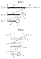
- Figure 1 shows a scheme of an arithmetic coding method or AC coding (Arithmetic Coding) according to the prior art.
- the starting point is a set of symbols [X 0 , X 1 , ..., X i , ..., X N-1 ] which is a length-N symbol sequence where each symbol belongs to an M-ary alphabet.
- the arithmetic encoding process is based on either the knowledge or the estimation of the probability of each character of the M-ary alphabet at time i, which we denote as p 1,i, p 2,i, ..., p M,i .
- the summary of the probability associated with the various characters of the M-ary alphabet, in each time, is equal to one.
- the arithmetic coding is based on the recursive interval partition according to a given probability, known as Elias coding, which encodes symbols through intervals.
- the source symbols are associated with sub-intervals of a starting interval so that they constitute a partition of it, i.e. they are not overlapped and their union is equal to the starting interval.
- the "current" interval is equal to the starting interval and it is set to [0,1).
- the "current" interval is partitioned into a set of M adiacent sub-intervals whose lengths are proportional to p 1 , p 2 , ...p M .
- the sub-interval representing the symbol X i is selected as the next "current" interval.
- the representation of the M-ary sequence can consist in any number within said final interval. For example, it is possible to select an endpoint of the final interval, the midpoint of the sub-interval or any other number belonging to the interval. For the transmission or for the writing on a numeric support such number will have to be transformed in a representation of it (typically binary) indicated codeword. In particular, for using the lowest bit rate per symbol the number can be chosen within the interval represented by the shortest codeword.
- the decoder is able to perform the same partitions, and hence, given the number within the final interval, it is able to reconstruct the sequence of partitions or selections that have generated it.
- the probability of the character 0 is indicated p 0 and the probability of the character 1 is indicated p 1 .
- the starting interval [0,1) is indicated 10, which is subdivided into two sub-intervals respectively proportional to probability p 0 and probability p 1 .
- the sub-interval corresponding to the symbol X 0 is selected within the "current" starting interval, in this case the sub-interval 11 having probability p 0 .
- This sub-interval 11 becomes now the new "current" interval and it is subdivided in two sub-intervals 12 and 13 respectively proportional to p 0 e p 1 .
- the sub-interval 12 of the new "current" interval 11 corresponding to the symbol X 1 is selected.
- the sub-interval 12 is then subdivided into two sub-intervals 14 and 15 respectively proportional to p 0 and p 1 .
- the sub-interval 15 is selected as final interval and any binary number included in said final interval 15 represent correctly the sequence X 0 X 1 X 2 .
- the arithmetic coding above disclosed provides a reversible description (without loss of information) of the input sequence X.
- the codewords representing X and Y are indicated C x and C y and the respective encoding rates are indicated R x and R y , expressed in bit rate.
- the side information Y can be coded respectively unambiguously (R y ⁇ H (Y)) or ambiguously (R y ⁇ H (Y)), in which H (Y) is the entropy of Y.
- the decoder can use the side information coded in any of the two modes.
- the unambiguity is given by the number selected in the final interval; using interval partition at each step of the arithmetic coding process ensures that each real number in the interval [0,1) belongs to only one out of all possible sequence of interval sub-divisions and selections, each of which corresponds to a different input information sequence.
- Distributed arithmetic coding is based in this case on the principle of inserting an ambiguity only in the sequence X so as to allow to use a less bit rate than in the case in which a sequence X non ambiguous is available.
- the sequence X can be decoded correctly if the side information is provided.
- the ambiguity is inserted using one of the three following modes.
- the distributed arithmetic coding employs a modified interval sub-division strategy.
- the sum of the probabilities of all the characters is greater than 1.
- said sub-interval In order to fit the enlarged sub-intervals inside the [0,1) interval, said sub-interval must be partially overlapped, as shown in figure 2 . This leads to a larger final interval which can be described using a shorter codeword.
- a certain number of bits are removed from the output codeword, and said bits removed are not communicated to the decoder.
- This bit remover process allows the encoder to employ a reduced bit rate for the encoding.
- Several removal patterns can be used, e.g. a number of equally spaced bits in the output strings can be removed, or a number of randomly selected bits, or a number of bit selected in such a way that the probability of decoding error is minimum, and so on.
- the distributed arithmetic coding employs a combination of the first and the second mode, that is the intervals are partially overlapped and some bits are removed from the output codeword.
- the design of the overlapping rule and bit removal rule is done in such a way as to achieve the desired bit rate.
- a cyclic redundancy code can be appended to the output codeword in order to facilitate the code error detection.
- the distributed arithmetic coding process can indeed be modified as follows in order to achieve a time sharing distributed arithmetic coding. If mode 1 encoders are used, this is applied to X and Y, with the provision that the i-th symbol X i is coded with overlapped intervals if and only if the i-th symbol Y i is not coded with overlapped intervals. This can be achieved e.g. by coding with overlapping the even symbol of X, while coding with classical partition without overlap the odd symbols. Conversely, odd symbols of Y are coded with overlapping interval while even symbols are coded onto separated intervals. Alternatively, the symbols to which the overlapping is applied are chosen according to a predetermined rule (for example a random sequence), in which it is allowed to have a different proportion of symbols with overlapping in each sequence.
- a predetermined rule for example a random sequence
- the same time sharing strategy can be used in the case of bit removal (mode 2) by guaranteeing that if a bit at a certain position i within the codeword of X is removed, the same position i is not selected for removal in the codeword representing Y.
- This time sharing approach allows one to design a joint sequential decoder able to reconstruct both correlated sequences.
- This algorithm can be extended to the case of multiple side information sources Y 1 , ..., Y M , where the available encoding rate is distributed in an arbitrary way among the sources.
- the distributed arithmetic coding is applied to each sources and, for each source, the symbols where overlap is used, as well as the amount of overlap, are chosen so as to achieve the desired bit rate for the coding and minimize the probability of decoding errors.
- FIG 2 an example of a binary distributed arithmetic coding method is shown, having namely M equal to 2, according to a embodiment of the invention.
- the probability and the modified probability of character 0 are respectively indicated p 0 and p ⁇ 0
- the probability and the modified probability of character 1 are respectively indicated p 1 and p ⁇ 1
- the starting interval [0,1) is indicated 16, and at initialization it is considered as "current" interval.
- Said interval [0,1) is subdivided into two sub-intervals partially overlapped 17 and 18, respectively proportional to probability p ⁇ 0 and probability p ⁇ 1 ; as a consequence of said overlapping, a certain amount of ambiguity is present in the final binary representation.
- the decoder side whenever the binary sequence points to the non overlapped region of a certain sub-interval, the corresponding information symbol can be decoded without ambiguity.
- the codeword points to the overlapped region, the source symbol can not be decoded unambiguously. In this latter case, the correlated side information must be provided to the decoder.
- the sub-interval corresponding to symbol X 0 is selected within the "current" starting interval, in this case the sub-interval 17 having the probability p ⁇ 0 .
- This sub-interval 17 becomes now the new "current" interval and it is subdivided in two sub-intervals 19 and 20 partially overlapped, respectively proportional to p ⁇ 0 and p ⁇ 1 .
- the sub-interval 19 of the new "current" interval 17 corresponding to symbol X 1 is selected.
- the sub-interval 19 is then subdivided into two sub-intervals 21 and 22, partially overlapped proportional relatively to p ⁇ 0 and p ⁇ 1 .
- the sub-interval 22 is selected as final interval, and any binary number within said final interval 22 represents correctly the sequence X 0 X 1 X 2 .
- source Y can be obviously applied to source Y.
- the symbols of said source Y can belong to an M-ary alphabet having M different from that of the alphabet associated with the source X.
- a starting interval [0,1) will be subdivided into M sub-intervals in which M is that associated with the source Y.
- the coding rate can be reduced to any desired value by means of suitable selection of parameter k.
- the aim of the distributed arithmetic decoding is to decode the source message X and the correlated side information Y.
- both X and Y are available to the decoder as entropy coded codeword C X and C Y .
- the decoder is arranged to perform a sequential search along a proper decoding tree where each node represents a state of the sequential arithmetic decoder.
- the decoding tree can be symbol "driven", when each transition is "driven” by the output of a given source symbol, or bit "driven”, when each transition represents the decoding of a fix number of coded bit, corresponding to a variable number of source symbols.
- the present invention applies for any decoder which uses a proper sequential search algorithm along an arithmetic decoding tree in order to maximize a certain metric, so as to select the most likely pair X and Y.
- a valid criterion is based on the Maximum A Posteriori (MAP) metric which is indicated with P (X 0 , X 1 , ..., X N-1
- MAP Maximum A Posteriori
- this metric also encompasses the case of Y is coded using a distributed arithmetic coding, and can be extended to the case of more than one side information Y.
- the MAP metric can also be replaced with an other criterion, as for example the minimum distance, according to the context or the complexity of the desired decoding.
- the decoding for data coded in the third mode (mode 3), i.e. combination of mode 1 and 2, can be obtained straightforwardly by extending the presented example of decoding.
- the proposed decoding method can be used to decode more than two correlated sources, provided that the decoding metric takes into account all the correlations.
- the decoding metric takes into account all the correlations.
- the side information is available at the decoder unambiguously; this is the case when the side information is encoded with a standard approach (for example the standard entropy coding).
- the correlated source X can be encoded with almost H (X
- the decoder must solve the ambiguity on X, resulting from intervals overlapping, by using the side information Y and the correlation model P (X
- This objective can be achieved with the sequential distributed decoding maximizing the MAP metric P (X
- C X , C Y Y).
- the received codeword C X is processed, which is a representation, typically binary, of a number lying in the final interval selected by the encoder.
- the decoder steps are as follows:
- FIG 3 a distributed arithmetic decoding branching tree for the binary case is illustrated.
- the decoder in not able to take a decision on the i-th symbol X i , indicated by the node 30.
- two alternative decoding attempts are pursued, branches 31 and 32.
- the input source is binary
- the MAP metric can be evaluated iteratively according to the following equation: P X 0 , X 1 , , X i
- C X , ... , C Y P ⁇ X 0 , X 1 , ... , X i - 1
- C X , Y ⁇ 1 if no branches are performed P X i
- the time sharing coding guarantees that the coding tree, corresponding to the decoding process of X and Y do not exhibit synchronous branches.
- the joint decoding process of the codeword C X and C Y can be obtained through the following steps:
- figure 4 branches of a distributed arithmetic decoding tree in case in which both X and Y represent binary sources are illustrated. It is worth noticing that the decoding technique described can be applied also for the case in which symbols of the source X belong to an M-ary alphabet and the symbols of the source Y belong to an other M-ary alphabet with M different from the preceding. In particular, in the example reported, the decoder is not able to take a decision on the i-th symbol Y i , indicated by the node 33, and on the (i+1)-th symbol X i+1 , indicated by the node 34.
- C X ,C Y ) and P(X 0 ,Y 1 ,...,Y i 0
- C X ,C Y ) are updated accordingly; on the other hand the opposite decision is considered, branches 36 and 38, and the MAP metric P(X 0 ,X 1 ,...,X i+1 1
- C X ,C Y ) and P(X 0 ,Y 1 ,...,Y i 1
- the decoder is not further able to take a decision on the (i+2)-th symbol X i+2 , indicated by the two alternative nodes 39 and 40 deriving respectively from the branches 37 and 38.
- two alternative decoding attempts are pursued, respectively branches 41 and 42, 41' and 42', to which can be applied the same considerations above explained with reference to branches 35, 36, 37 and 38.
- the coding method so uses two tree representations for X and Y in order to find the two sequences maximizing the corresponding MAP metrics P(X
- the tree for Y can generate branches.
- the MAP metric can be updated as follows: P Y 0 , Y 1 , , Y i
- C X , C Y P ⁇ Y 0 , Y 1 , ... , Y i - 1
- P(X i m
- the present decoder can be generalized to the case of multiple correlated sources, provided that the trees of all the correlated sources are extended in parallel.
- the decoding can be achieved with an approach that is very similar to the previously described cases. From the implementation point of view, it is better to perform a sequential search along a bit "driven" decoding tree. In fact such a tree presents a branching for every bit that has been removed during the coding process.
- the decoding method is a sequential process that can decode a given number of bit of the received codeword C X , and output the maximum number of source symbols.
- the number of decoded source symbols depends on the numerical precision given by the available binary digits of C X .
- the metric can be evaluated iteratively as in the previous implementation.
- Each path in the tree corresponds to a variable number of source symbols, obtained decoding a truncated representation of the codeword C x .
- Each node metric can be obtained using the conditional probability model, relating to the sequentially decoded symbol and the side information. In other words, the node metric must be updated according to the new source symbols that must be decoded, given the increased codeword precision, when one or more bit are decoded.
Landscapes
- Engineering & Computer Science (AREA)
- Theoretical Computer Science (AREA)
- Compression, Expansion, Code Conversion, And Decoders (AREA)
- Error Detection And Correction (AREA)
- Computer And Data Communications (AREA)
- Hardware Redundancy (AREA)
Abstract
Description
- The present invention relates to a method of distributed source coding.
- More specifically the invention relates to a method to perform the coding and the decoding of communication data coming from statistically dependent sources.
- In recent years, distributed source coding has received an increasing attention from the academics that address of analysis and signals processing. The distributed source coding considers the situation in which two or more statistically dependent data sources must be encoded by two separate encoders that are not allowed to talk each other, i.e., when the two sources are not jointly available (i.e., they are not within the same device) and therefore the communication between them would be impossible or very expensive, as in the case of a network of wireless sensors. In this case, each encoder has available only the data coming from one of the two sources. Equally appealing is the possibility of applying distributed source coding principles to situations where a single source is artificially subdivided into correlated sub-sources that are encoded separately, e.g., different frames of a video sequence. In this case the advantage is that decorrelation among the sub-sources is no longer required, thus simplifying the encoder (though at the expenses of the decoder).
- The two encoders can perform lossless compression of the two sources each by using a bit rate greater than the entropy of either source; however, this type of separate compression constitutes a loss of efficiency with respect to the use of an encoder that jointly compresses the two sources, since in this case a bit rate equal to the joint entropy of the sources could be used, which is smaller than the entropy of each source.
- The distributed source coding theory has proved that, under certain assumptions, the same result as the joint coding can be achieved by using two separate encoders, provided that the two sources are decoded by a joint decoder. It is possible to get this performing a standard encoding of one of the two sources (called "side information") at its entropy value, and an "ambiguous" encoding of the other source at a rate lower than its entropy, with no information about the first source available at the second encoder. A source is encoded ambiguously when data of said source are transmitted in the form a sequence of symbols so that non to guarantee at the decoder a perfect and univocal acknowledgement of the symbol transmitted.
- The encoders which perform the distributed source coding are typically implemented using channel codes, i.e. by representing the source using its syndrome (or the parity bits) for a given channel code suitable for a given correlation amount between the two sources. The channel codes are used because they, having the side information, allow to perform the decoding of a source encoded ambiguously with a minimum error probability.
- The distributed source coding theory comprises not only lossless compression but also lossy compression; it has been shown that, under certain condition, there is no performance loss in using distributed source coding as opposed to joint coding. In practice, lossy distributed source coding is typically implemented using a standard quantizier followed by lossless distributed source coding (entropy coding), while the decoder consists of a joint entropy decoder followed by a joint dequantizer.
- The applications of distributed source coding schemes to realistic signals are typically limited by some problems. In particular, for example, channel codes require very large data blocks (typically in excess of 10.000 symbols). This requirement is not always compatible with practical applications, where the basic units to be encoded are of the order of a few hundreds to a few thousands symbols. Furthermore, channel codes require that the symbols contained in each block follow always a stationary statistical distribution, hypothesis not suitable for data as images and video sequences, for example. Moreover the conditional entropy of a stationary distribution constraints the bit rate.
- Channel codes have an high coding complexity, typically in the order of the square of the dimension of the data block, and therefore this complexity rises very quickly when the dimension of the block increases; other side, a big block dimension is a prerequisite for the use of this channel codes, from which the high complexity of the coding process derives.
- An object of the present invention is to propose a source encoding and decoding method which can overcome the above stated problems.
- This and other objects are achieved according to the invention with a coding and decoding method whose main characteristics are defined in
claims 1 and 7. - Further characteristics and advantages of the invention will become clear from the following detailed description, given purely by way of non limiting example, with reference to the attached drawings, in which:
-
figure 1 is an illustrative scheme of a binary arithmetic coding method according to the prior art; -
figure 2 is a scheme related to a binary arithmetic distributed coding method according to the invention; -
figure 3 is a scheme of a branch of a distributed arithmetic decoding tree; and -
figure 4 is a scheme of branches of a distributed arithmetic decoding tree having a side information ambiguously coded. -
Figure 1 shows a scheme of an arithmetic coding method or AC coding (Arithmetic Coding) according to the prior art. In the arithmetic coding the starting point is a set of symbols [X0, X1, ..., Xi, ..., XN-1] which is a length-N symbol sequence where each symbol belongs to an M-ary alphabet. The arithmetic encoding process is based on either the knowledge or the estimation of the probability of each character of the M-ary alphabet at time i, which we denote as p1,i, p2,i, ..., pM,i. The summary of the probability associated with the various characters of the M-ary alphabet, in each time, is equal to one. For simplicity, we will denote the set of probabilities as p1, p2, ..., pM though it is intended that these probabilities can vary at each encode step, e.g., when an estimation algoritm based on symbol statistics is used. - The arithmetic coding is based on the recursive interval partition according to a given probability, known as Elias coding, which encodes symbols through intervals. The source symbols are associated with sub-intervals of a starting interval so that they constitute a partition of it, i.e. they are not overlapped and their union is equal to the starting interval.
- At the beginning, the "current" interval is equal to the starting interval and it is set to [0,1). For each input symbol Xi of the sequence to be coded, the "current" interval is partitioned into a set of M adiacent sub-intervals whose lengths are proportional to p1, p2, ...pM. The sub-interval representing the symbol Xi is selected as the next "current" interval.
- After all N symbols have been processed, the sequence is represented by the last "current" interval, denoted as final interval.
- The representation of the M-ary sequence can consist in any number within said final interval. For example, it is possible to select an endpoint of the final interval, the midpoint of the sub-interval or any other number belonging to the interval. For the transmission or for the writing on a numeric support such number will have to be transformed in a representation of it (typically binary) indicated codeword. In particular, for using the lowest bit rate per symbol the number can be chosen within the interval represented by the shortest codeword.
- Knowing or estimating the probabilities of the symbols, the decoder is able to perform the same partitions, and hence, given the number within the final interval, it is able to reconstruct the sequence of partitions or selections that have generated it.
- The example of
figure 1 shows a method of binary arithmetic coding, namely having M equal to 2, which codes a string of N=3 symbols, where the symbols are X0=0, X1=0 e X2=1. The probability of thecharacter 0 is indicated p0 and the probability of thecharacter 1 is indicated p1. Infigure 1 the starting interval [0,1) is indicated 10, which is subdivided into two sub-intervals respectively proportional to probability p0 and probability p1. - Since the first symbol of the sequence to encode is X0=0, the sub-interval corresponding to the symbol X0 is selected within the "current" starting interval, in this case the sub-interval 11 having probability p0. This sub-interval 11 becomes now the new "current" interval and it is subdivided in two
sub-intervals - At this point, since the second symbol of the sequence to transmit is X1=0, the
sub-interval 12 of the new "current" interval 11 corresponding to the symbol X1 is selected. Thesub-interval 12 is then subdivided into twosub-intervals - Since now the third symbol of the sequence to transmit is X2=1, the
sub-interval 15 is selected as final interval and any binary number included in saidfinal interval 15 represent correctly the sequence X0 X1 X2. - The arithmetic coding above disclosed provides a reversible description (without loss of information) of the input sequence X.
- It will be now disclosed the distributed arithmetic coding according to the invention. It provides, differently from the simple arithmetic coding above described, an ambiguous and more compressed description of the sequence X, which can be decoded losslessly only if the side information Y is available at the receiver; said receiver is a soft joint decoder.
- The codewords representing X and Y are indicated Cx and Cy and the respective encoding rates are indicated Rx and Ry, expressed in bit rate.
- The side information Y can be coded respectively unambiguously (Ry ≥ H (Y)) or ambiguously (Ry < H (Y)), in which H (Y) is the entropy of Y. The decoder can use the side information coded in any of the two modes.
- It is therefore possible to perform two different coding, the first having the side information available unambiguously, the second having the side information available ambiguously.
- In the coding with side information available unambiguously, the unambiguity is given by the number selected in the final interval; using interval partition at each step of the arithmetic coding process ensures that each real number in the interval [0,1) belongs to only one out of all possible sequence of interval sub-divisions and selections, each of which corresponds to a different input information sequence.
- Distributed arithmetic coding is based in this case on the principle of inserting an ambiguity only in the sequence X so as to allow to use a less bit rate than in the case in which a sequence X non ambiguous is available. The sequence X can be decoded correctly if the side information is provided. The ambiguity is inserted using one of the three following modes.
- In the first mode (mode 1), the distributed arithmetic coding employs a modified interval sub-division strategy. A set of intervals whose amplitude is increased and proportional to a modified set of probabilities p̃j such that p̃j ≥ pj is used, where the subscript j=1, ...,M indicates the different characters of the coding alphabet. As a consequence, the sum of the probabilities of all the characters is greater than 1. In order to fit the enlarged sub-intervals inside the [0,1) interval, said sub-interval must be partially overlapped, as shown in
figure 2 . This leads to a larger final interval which can be described using a shorter codeword. - In mode 2 (mode 2), the distributed arithmetic coders employs the same interval partition as the standard arithmetic coding, i.e. p̃j = Pj. In order to insert some ambiguity, a certain number of bits are removed from the output codeword, and said bits removed are not communicated to the decoder. This bit remover process allows the encoder to employ a reduced bit rate for the encoding. Several removal patterns can be used, e.g. a number of equally spaced bits in the output strings can be removed, or a number of randomly selected bits, or a number of bit selected in such a way that the probability of decoding error is minimum, and so on.
- In the third mode (mode 3), the distributed arithmetic coding employs a combination of the first and the second mode, that is the intervals are partially overlapped and some bits are removed from the output codeword. The design of the overlapping rule and bit removal rule is done in such a way as to achieve the desired bit rate.
- Optionally, a cyclic redundancy code can be appended to the output codeword in order to facilitate the code error detection.
- In the encoding with side information available ambiguously a coding with a bit rate close to the joint entropy is achieved by encoding both X and Y with ambiguity rather than leaving all the ambiguity only in X.
- The distributed arithmetic coding process can indeed be modified as follows in order to achieve a time sharing distributed arithmetic coding. If
mode 1 encoders are used, this is applied to X and Y, with the provision that the i-th symbol Xi is coded with overlapped intervals if and only if the i-th symbol Yi is not coded with overlapped intervals. This can be achieved e.g. by coding with overlapping the even symbol of X, while coding with classical partition without overlap the odd symbols. Conversely, odd symbols of Y are coded with overlapping interval while even symbols are coded onto separated intervals. Alternatively, the symbols to which the overlapping is applied are chosen according to a predetermined rule (for example a random sequence), in which it is allowed to have a different proportion of symbols with overlapping in each sequence. - The same time sharing strategy can be used in the case of bit removal (mode 2) by guaranteeing that if a bit at a certain position i within the codeword of X is removed, the same position i is not selected for removal in the codeword representing Y. This time sharing approach allows one to design a joint sequential decoder able to reconstruct both correlated sequences.
- This algorithm can be extended to the case of multiple side information sources Y1, ..., YM, where the available encoding rate is distributed in an arbitrary way among the sources. In this case, the distributed arithmetic coding is applied to each sources and, for each source, the symbols where overlap is used, as well as the amount of overlap, are chosen so as to achieve the desired bit rate for the coding and minimize the probability of decoding errors.
- In
figure 2 an example of a binary distributed arithmetic coding method is shown, having namely M equal to 2, according to a embodiment of the invention. The method encodes a string of N = 3 symbols, in which the symbols are X0 = 0, X1 = 0 e X2 = 1. The probability and the modified probability ofcharacter 0 are respectively indicated p0 and p̃ 0, and the probability and the modified probability ofcharacter 1 are respectively indicated p1 and p̃ 1 - In such figure the starting interval [0,1) is indicated 16, and at initialization it is considered as "current" interval. Said interval [0,1) is subdivided into two sub-intervals partially overlapped 17 and 18, respectively proportional to probability p̃ 0 and probability p̃ 1; as a consequence of said overlapping, a certain amount of ambiguity is present in the final binary representation. In particular, at the decoder side, whenever the binary sequence points to the non overlapped region of a certain sub-interval, the corresponding information symbol can be decoded without ambiguity. On the contrary, if the codeword points to the overlapped region, the source symbol can not be decoded unambiguously. In this latter case, the correlated side information must be provided to the decoder.
- Since the first symbol of the sequence to encode in this case is X0 = 0, the sub-interval corresponding to symbol X0 is selected within the "current" starting interval, in this case the sub-interval 17 having the probability p̃ 0. This sub-interval 17 becomes now the new "current" interval and it is subdivided in two
sub-intervals - At this time, since the second symbol of the sequence to transmit is X1 = 0, the sub-interval 19 of the new "current"
interval 17 corresponding to symbol X1 is selected. The sub-interval 19 is then subdivided into twosub-intervals - Since now the third symbol of the sequence to transmit is X2 = 1, the sub-interval 22 is selected as final interval, and any binary number within said
final interval 22 represents correctly the sequence X0X1X2. - The method above disclosed with reference to source X can be obviously applied to source Y. The symbols of said source Y can belong to an M-ary alphabet having M different from that of the alphabet associated with the source X. In this case, for the source Y a starting interval [0,1) will be subdivided into M sub-intervals in which M is that associated with the source Y.
- The average rate spent to perform the distributed arithmetic coding, expressed in bit per input symbol, is given by the following equation:

- As an example, each probability can be amplified by a factor αj ≥ 1, from which derives that p̃j = αjpj. As a consequence, the average coding rate R becomes the following:

where rj = -log2pj and δrj = log2αj, and this last represents the number of bits removed from the binary representation of the i-th symbol. - In one embodiment of the present invention, the amplification factors αj can change at each encoding step, i.e. αj = αj,i, according to a suitable rule that determines the average instantaneous rate to assign to the i-th input symbol.
- In an other embodiment of the present invention, one may want to use constant αj = α. In an other embodiment one may want to keep constant the ratio δrj/rj = k, which is equal to setting αj = pj -k, with 0 ≤ k ≤ 1. In this latter case, the expression of the average coding rate R can be further simplified as follows:

where H is the entropy of the probability model, i.e.
- It is evident that the coding rate can be reduced to any desired value by means of suitable selection of parameter k.
- It will be now disclosed the distributed arithmetic decoding method object of the invention.
- The aim of the distributed arithmetic decoding is to decode the source message X and the correlated side information Y. In the most general case both X and Y are available to the decoder as entropy coded codeword CX and CY. The decoder is arranged to perform a sequential search along a proper decoding tree where each node represents a state of the sequential arithmetic decoder. The decoding tree can be symbol "driven", when each transition is "driven" by the output of a given source symbol, or bit "driven", when each transition represents the decoding of a fix number of coded bit, corresponding to a variable number of source symbols.
- The present invention applies for any decoder which uses a proper sequential search algorithm along an arithmetic decoding tree in order to maximize a certain metric, so as to select the most likely pair X and Y. Several metrics are possible; a valid criterion is based on the Maximum A Posteriori (MAP) metric which is indicated with P (X0, X1, ..., XN-1|CX, CY).
- It is worth pointing out that this metric also encompasses the case of Y is coded using a distributed arithmetic coding, and can be extended to the case of more than one side information Y.
- The MAP metric can also be replaced with an other criterion, as for example the minimum distance, according to the context or the complexity of the desired decoding.
- Several embodiments of the decoding method will be disclosed in the following. In particular, different decoding methods in case of side information coded unambiguously or ambiguously will be disclosed.
- At first it is considered the case in which the encoding has been performed with interval overlapping (mode 1). In this case it is used a symbol "driven" decoding tree.
- Then, it is presented the achievement of a decoding in the case in which the encoding has been performed with bit removal (mode 2). In this case a bit "driven" decoding tree is used.
- The decoding for data coded in the third mode (mode 3), i.e. combination of
mode 1 and 2, can be obtained straightforwardly by extending the presented example of decoding. - It is worth noticing that the proposed decoding method can be used to decode more than two correlated sources, provided that the decoding metric takes into account all the correlations. As an example, if the source X is correlated with source Y1, ..., YM, its decoding metric turns out to be P (X|CX, CY1, ..., CYM).
- In a first embodiment of the decoding method we assume that the side information is available at the decoder unambiguously; this is the case when the side information is encoded with a standard approach (for example the standard entropy coding). The correlated source X can be encoded with almost H (X|Y) bit per symbol, by means of the proposed distributed arithmetic coding with properly overlapped intervals. In this particular situation the decoder must solve the ambiguity on X, resulting from intervals overlapping, by using the side information Y and the correlation model P (X|Y).
- This objective can be achieved with the sequential distributed decoding maximizing the MAP metric P (X|CX, CY=Y).
- In the decoding the received codeword CX is processed, which is a representation, typically binary, of a number lying in the final interval selected by the encoder. The decoder steps are as follows:
- 1) Initialize the current interval to [0,1).
- 2) Subdivide the interval according to the probabilities p̃j .
- 3) Initialize the coding tree.
- 4) While the number of the decoded symbols is less than N (and/or the termination condition is met):
- for every node in the tree:
- compare CX with the current interval subdivision;
- if CX belongs to the non overlapped portion of a certain interval, decode the corresponding symbol Xi without ambiguity and select the corresponding interval for next iteration of this node;
- if CX lies in the overlapped region between two or more intervals, perform a decoding branching; store K alternative paths, corresponding to the K ≤ M alternative symbols Xi that can be decoded, upgrade their MAP metrics and select the corresponding interval for next iteration;
- optionally adopt pruning techniques in order to limit the number of most likely paths stored in memory; for example it can be used the Viterbi algorithm, stack and "M" algorithm.
- for every node in the tree:
- 5) Output the sequence corresponding to the most likely path in the tree.
- In
figure 3 a distributed arithmetic decoding branching tree for the binary case is illustrated. In particular, in the reported example, the decoder in not able to take a decision on the i-th symbol Xi, indicated by thenode 30. As a consequence, two alternative decoding attempts are pursued,branches branch 31, and the MAP metric P (X0, X1, ..., Xi=0|CX, CY) is updated accordingly. On the other hand the opposite decision is considered,branch 32, and MAP metric P(X0, X1, ..., Xi=1|CX, CY) is evaluated. - Given the correlation model in terms of probability distribution P(X|Y), the MAP metric can be evaluated iteratively according to the following equation:

with:
- In most practical cases the adopted correlation model is memoryless, or the correlation is considered only symbol by symbol, and hence


- The same approach can be extended to correlation models with memory. It is worth noticing that, for complexity reasons, most applications will adopt a logarithmic implementation of the previous metrics so as to substitute multiplications with additions.
- In a second embodiment of the decoding method it is assumed that the side information is available at the decoder ambiguously. It is therefore assumed that CX and CY are ambiguous representations of corresponding sources, obtained by means of the time sharing distributed arithmetic coding with interval overlapping.
- At the decoder side, the time sharing coding guarantees that the coding tree, corresponding to the decoding process of X and Y do not exhibit synchronous branches. The joint decoding process of the codeword CX and CY can be obtained through the following steps:
- 1) Initialize the current interval for X, IX to [0,1) and subdivide it according to the probability distribution of X.
- 2) Initialize the current interval for Y, IY to [0,1) and subdivide it according to the probability distribution of Y.
- 3) Initialize the decoding tree for X.
- 4) Initialize the decoding tree for Y.
- 5) While the number of decoded symbols is less than N (and/or the termination condition is met):
- extend the branches of all nodes in the non ambiguous tree at time i;
- for all the nodes in the tree that can generate ambiguity at time i, set Z0 i = [Z0, Z1, ..., Zi] with Zj = Xj or Zj = Yj for 0 ≤j≤i, according to either the ambiguity lies in Xi or Yi respectively; moreover, set CZ=CX or CZ=CY based on the ambiguity;
- compare the codeword CZ with the current interval subdivisions;
- if CZ belongs to the non overlapped portion of a certain interval, decode the corresponding symbol Zi without ambiguity, and select the corresponding interval for the next iteration of this node;
- if CZ lies in the overlapped region between at least two intervals, perform a decoding branching; store K≤M alternative paths, corresponding to the alternative symbols Zi that can be decoded, update their MAP metrics P(Zi 0|CX,CY) and select the corresponding interval for next iteration;
- optionally adopt pruning techniques in order to limit the number of most likely paths stored in memory; for example it can be used the Viterbi algorithm, stack and algorithm "M".
- 6) Output the sequence corresponding to the most likely path in the tree.
- In
figure 4 branches of a distributed arithmetic decoding tree in case in which both X and Y represent binary sources are illustrated. It is worth noticing that the decoding technique described can be applied also for the case in which symbols of the source X belong to an M-ary alphabet and the symbols of the source Y belong to an other M-ary alphabet with M different from the preceding. In particular, in the example reported, the decoder is not able to take a decision on the i-th symbol Yi, indicated by thenode 33, and on the (i+1)-th symbol Xi+1, indicated by thenode 34. As a consequence, two alternative decoding attempts are pursued, respectivelybranches branches branches branches - As far as X is concerned, the decoder is not further able to take a decision on the (i+2)-th symbol Xi+2, indicated by the two
alternative nodes branches branches branches - The coding method so uses two tree representations for X and Y in order to find the two sequences maximizing the corresponding MAP metrics P(X|CX,CY) and P (Y|CX,CY). The fact that, at a given time instant, there is only one tree generating ambiguous decisions permits to evaluate the necessary MAP metric.
- Let us consider that, at time i, the decoding tree for X does not contain ambiguity. This means that the MAP metrics of all nodes in the tree are kept unchanged, so apply the following relation:

- On the contrary, the tree for Y can generate branches. In such a case the MAP metric can be updated as follows:

- In absence of branches, P(Yi|CX,CY) = 1.
- In the opposite case the following expression can be used:

- In the previous equality a memoryless correlation model

is adopted for simplicity but the proposed approach can be extend to the case with memory. - Finally, the term P(Xi=m"CX,CY) can be evaluated on the complementary decoding tree for X as given by the following equation:

- If pruning techniques are adopted, not all the nodes in the tree are available and the following estimator for the term P(Xi=m|CX,CY)can be used:

- It is worth pointing out that the present decoder can be generalized to the case of multiple correlated sources, provided that the trees of all the correlated sources are extended in parallel.
- If data have been coded with bit removal (mode 2), the decoding can be achieved with an approach that is very similar to the previously described cases. From the implementation point of view, it is better to perform a sequential search along a bit "driven" decoding tree. In fact such a tree presents a branching for every bit that has been removed during the coding process.
- In the following, for simplicity, only the case with unambiguous coding for the side information is presented. Of course, it is possible to extend everything here disclosed to the case in which also the side information is coded ambiguously, as above described.
- The decoding method is a sequential process that can decode a given number of bit of the received codeword CX, and output the maximum number of source symbols. The number of decoded source symbols depends on the numerical precision given by the available binary digits of CX.
- The following steps allow to build a bit "driven" decoding tree so as to find the sequence X, maximizing the metric P(X|CX,CY=Y).
- 1) Initialize the current interval to [0,1).
- 2) Subdivide the interval according to the probability p̃j .
- 3) Initialize the decoding tree.
- 4) While all the codeword digits are not consumed:
- for all the nodes in the tree:
- decode all the codeword bits preceding the next removed bit, output the corresponding source symbol and use them to update the metric P(X|CX,Y);
- perform a branching corresponding to the removed codeword bit; decode a 0 codeword bit, decode the corresponding source symbol and updated metric; do the same for the 1 codeword bit;
- optionally adopt pruning techniques in order to limit the number of most likely paths stored in memory; for example it is possible to use the Viterbi algorithms, stack and "M" algorithm; it is possible to use also other constraints to prune non suitable paths, such as the maximum number of decoded symbols or known termination conditions.
- for all the nodes in the tree:
- 5) Output the sequence corresponding to the most likely path in the tree.
- The metric can be evaluated iteratively as in the previous implementation. Each path in the tree corresponds to a variable number of source symbols, obtained decoding a truncated representation of the codeword Cx. Each node metric can be obtained using the conditional probability model, relating to the sequentially decoded symbol and the side information. In other words, the node metric must be updated according to the new source symbols that must be decoded, given the increased codeword precision, when one or more bit are decoded.
- Naturally, the principle of the invention remaining the same, the embodiments and details of construction may be widely varied with respect to those described and illustrated purely by way of non limiting example, without thereby departing from the scope of protection of the present invention as defined in the appended claims.
Claims (7)
- Distributed arithmetic coding method of a first data source (X) having an associated entropy (H), and at least a second data source (Y) statistically correlated to the first (X), in which each of said sources (X,Y) is associated with a respective sequence of symbols (X0, X1, ..., XN-1; Y0, Y1, YN-1), in which each symbol belongs to an M-ary alphabet, wherein M can be different for the two sources (X,Y), with associated a group of probabilities (p1, ..., pM) whose values are included in the interval from 0 to 1;
the method being characterized by coding said first source (X) ambiguously with a predetermined number of elements per symbol (X0, X1, ..., XN-1), in particular bit per symbol (X0, X1, ..., XN-1), less than its entropy (H). - Arithmetic coding method according to claim 1, in which said first source (X) is coded ambiguously performing the following steps:a) subdivide a starting interval of real number (16) assumed equal to interval from 0 to 1, in M sub-intervals (17, 18) in which M assumes the value associated with the first source (X), said sub-intervals having predetermined lengths bigger or equal than the lengths corresponding to values of the probabilities (p1,..., pM) of the M-ary alphabet associated with the first source (X), so that at least two of said sub-intervals (17, 18) are partially overlapped;b) select a first sub-interval (17) of said starting interval (16) corresponding to the first symbol (X0) of said sequence;c) repeat step a) using as new starting interval said first sub-interval (17);d) select a second sub-interval (19) of said new starting interval (17) corresponding to the second symbol (X1) of said sequence (X0, X1, ..., XN-1);e) repeat steps c) and d) updating the starting interval according to the next symbols of the sequence (X0, X1, ..., XN-1) until all the symbols are depleted;f) select any number within the last sub-interval (22) corresponding to the last symbol of the sequence (X0, X1, ..., XN-1) as representative of the entire sequence (X0, X1, ..., XN-1) so coded and transform it in a predetermined representation, indicated codeword, constituted by a plurality of said elements, in particular a plurality of bit.
- Coding method according to claim 1, in which the sequence (X0, X1, ..., XN-1) associated with said first source (X) in encoded ambiguously performing to the following steps:i) subdivide a starting interval of real numbers (16), assumed equal to interval from 0 to 1 in M sub-intervals in which M assumes the value associated with the first source (X), said sub-intervals having predetermined lengths equal to the lengths corresponding to the values of probabilities (p1, ..., pM) of the M-ary alphabet associated to the first source (X), so that said sub-intervals are not partially overlapped;ii) remove a predetermined number of elements of the codeword corresponding to the sequence (X0, X1, ..., XN-1).
- Coding method according to claim 2, in which the sequence (X0, X1, ..., XN-1) associated with said first source (X) is coded ambiguously, further performing the step of:- remove a predetermined number of elements of the codeword corresponding to the sequence (X0, X1, ..., XN-1).
- Coding method according to claim 2, in which the second data source (Y) is encoded ambiguously and in which, when step a) is performed on a predetermined symbol of the first source (X), on the corresponding symbol of the at least one second data source (Y) is performed the following step, substitutive of said step a):- subdivide a starting interval of real numbers (16) assumed equal to interval from 0 to 1 in M sub-intervals, in which M assumed the value associated with the second source (Y), said sub-intervals having predetermined lengths equal to the lengths corresponding to the values of the probabilities (p1, pM) of the M-ary alphabet associated with the second source (Y), so that said sub-intervals are not partially overlapped.
- Coding method according to claim 3, in which the second data source (Y) is encoded ambiguously and in which the step ii) is performed on a predetermined group of elements of the codeword corresponding to the first source (X), and the ii) step is performed on an other predetermined group of elements of the codeword corresponding to at least a second data source (Y).
- Distributed arithmetic decoding method comprising the steps of:a) acquire at least two codewords (CX, CY) associated respectively with a first data source (X) and with at least a second data source (Y) statistically correlated to the first (X), in which each of said codewords (CX, CY) describes, even ambiguously, a respective sequence of source symbols (X0, X1, ..., XN-1; Y0, Y1, ..., YN-1), in which each symbol belongs to an M-ary alphabet, with M even different for the two sources (X, Y), with an associated group of probabilities (p1, ... , pM); said at least two codewords (Cx, Cy) being linked to said symbols sequence (X0, X1, ..., XN-1; Y0, Y1, ..., YN-1) by a predetermined correlation relation;b) subdivide at least a starting interval of real numbers associated with a source (X or Y), assumed equal to interval from 0 to 1, in M sub-intervals, in which M assumes the values associated with said source (X or Y), said sub-intervals having predetermined lengths bigger or equal to the lengths corresponding to the values of the probabilities (p1, ..., pM) of the M-ary alphabet associated with said source (X or Y), so that at least two of said sub-intervals are partially overlapped;c) initialize at least a decoding tree made up of a group of nodes each corresponding to a symbol of at least one of the at least two codewords (CX, CY);d) compare at least a codeword (CX, CY) with the sub-intervals;e1) if said at least one codeword (CX, CY) belongs to the portion non overlapped of a sub-interval, decode the corresponding symbol and select the corresponding sub-interval as a new starting interval;e2) if said at least one codeword (CX,CY) belongs to the portion overlapped between at least two sub-intervals, memorize K≤M alternative paths corresponding to the K symbols that can be decoded, update their correlation relation and select the corresponding sub-interval as new starting interval;f) repeat the operations d) and e1) or e2) for all the nodes of the tree;g) output the sequence corresponding to most likely path in the at least one decoding tree.
Priority Applications (5)
| Application Number | Priority Date | Filing Date | Title |
|---|---|---|---|
| AT07425116T ATE511717T1 (en) | 2007-03-01 | 2007-03-01 | DISTRIBUTED ARITHMETIC CODING METHOD |
| PL07425116T PL1965497T3 (en) | 2007-03-01 | 2007-03-01 | Distributed arithmetic coding method |
| EP07425116A EP1965497B8 (en) | 2007-03-01 | 2007-03-01 | Distributed arithmetic coding method |
| ES07425116T ES2367747T3 (en) | 2007-03-01 | 2007-03-01 | DISTRIBUTED ARITHMETIC CODING METHOD. |
| PCT/IB2008/050721 WO2008104948A2 (en) | 2007-03-01 | 2008-02-28 | Distributed arithmetic coding method |
Applications Claiming Priority (1)
| Application Number | Priority Date | Filing Date | Title |
|---|---|---|---|
| EP07425116A EP1965497B8 (en) | 2007-03-01 | 2007-03-01 | Distributed arithmetic coding method |
Publications (3)
| Publication Number | Publication Date |
|---|---|
| EP1965497A1 true EP1965497A1 (en) | 2008-09-03 |
| EP1965497B1 EP1965497B1 (en) | 2011-06-01 |
| EP1965497B8 EP1965497B8 (en) | 2011-10-05 |
Family
ID=38308663
Family Applications (1)
| Application Number | Title | Priority Date | Filing Date |
|---|---|---|---|
| EP07425116A Not-in-force EP1965497B8 (en) | 2007-03-01 | 2007-03-01 | Distributed arithmetic coding method |
Country Status (5)
| Country | Link |
|---|---|
| EP (1) | EP1965497B8 (en) |
| AT (1) | ATE511717T1 (en) |
| ES (1) | ES2367747T3 (en) |
| PL (1) | PL1965497T3 (en) |
| WO (1) | WO2008104948A2 (en) |
Cited By (1)
| Publication number | Priority date | Publication date | Assignee | Title |
|---|---|---|---|---|
| CN115276900A (en) * | 2022-06-06 | 2022-11-01 | 北京邮电大学 | Information transmission method and system for joint polarization of information source and information channel of distributed information source |
Citations (1)
| Publication number | Priority date | Publication date | Assignee | Title |
|---|---|---|---|---|
| US20020176494A1 (en) * | 2001-01-30 | 2002-11-28 | Qian Zhao | Lossless and near-lossless source coding for multiple access networks |
-
2007
- 2007-03-01 AT AT07425116T patent/ATE511717T1/en not_active IP Right Cessation
- 2007-03-01 PL PL07425116T patent/PL1965497T3/en unknown
- 2007-03-01 ES ES07425116T patent/ES2367747T3/en active Active
- 2007-03-01 EP EP07425116A patent/EP1965497B8/en not_active Not-in-force
-
2008
- 2008-02-28 WO PCT/IB2008/050721 patent/WO2008104948A2/en not_active Ceased
Patent Citations (1)
| Publication number | Priority date | Publication date | Assignee | Title |
|---|---|---|---|---|
| US20020176494A1 (en) * | 2001-01-30 | 2002-11-28 | Qian Zhao | Lossless and near-lossless source coding for multiple access networks |
Non-Patent Citations (2)
| Title |
|---|
| QIAN ZHAO ET AL: "Lossless and Near-Lossless Source Codingfor Multiple Access Networks", IEEE TRANSACTIONS ON INFORMATION THEORY, IEEE SERVICE CENTER, PISCATAWAY, NJ, US, vol. 49, no. 1, January 2003 (2003-01-01), XP011074673, ISSN: 0018-9448 * |
| THOMAS GUIONNET ET AL: "Soft decoding and synchronization of arithmetic and quasi-arithmetic codes : application to image transmission over noisy channels", JOINT PHOTOGRAPHIC EXPERT GROUP CONFERENCE, CROWBOROUGH : JPEG FORUM LTD, GB, 22 July 2003 (2003-07-22), XP017205077 * |
Cited By (2)
| Publication number | Priority date | Publication date | Assignee | Title |
|---|---|---|---|---|
| CN115276900A (en) * | 2022-06-06 | 2022-11-01 | 北京邮电大学 | Information transmission method and system for joint polarization of information source and information channel of distributed information source |
| CN115276900B (en) * | 2022-06-06 | 2023-10-31 | 北京邮电大学 | Information transmission method and system for joint polarization of distributed source channels |
Also Published As
| Publication number | Publication date |
|---|---|
| WO2008104948A2 (en) | 2008-09-04 |
| ATE511717T1 (en) | 2011-06-15 |
| EP1965497B8 (en) | 2011-10-05 |
| EP1965497B1 (en) | 2011-06-01 |
| ES2367747T3 (en) | 2011-11-08 |
| WO2008104948A3 (en) | 2008-10-30 |
| PL1965497T3 (en) | 2012-02-29 |
Similar Documents
| Publication | Publication Date | Title |
|---|---|---|
| JP3923618B2 (en) | Method for converting information bits having error correcting code and encoder and decoder for performing the method | |
| JP3923617B2 (en) | Method for converting information bits having error correcting code and encoder and decoder for performing the method | |
| US7265692B2 (en) | Data compression system based on tree models | |
| CN1210872C (en) | Reduced Search Symbol Evaluation Algorithm | |
| Yang et al. | Fixed-slope universal lossy data compression | |
| US12080384B2 (en) | Method for compressing genomic data | |
| CN111670543B (en) | Multi-component coding for signal shaping | |
| CN109768846B (en) | Hole drilling method, system, device and medium based on two-core three-core mixed polarization code | |
| CN111049527A (en) | Image coding and decoding method | |
| US7249311B2 (en) | Method end device for source decoding a variable-length soft-input codewords sequence | |
| McBain et al. | Homophonic coding for the noisy nanopore channel with constrained Markov sources | |
| EP0827299A3 (en) | Data receiver and data receiving method with soft decoding | |
| JP4169738B2 (en) | Apparatus and method for robust decoding of arithmetic codes | |
| EP1965497B1 (en) | Distributed arithmetic coding method | |
| Zhou et al. | Distributed arithmetic coding with interval swapping | |
| EP3656058A1 (en) | Device and method for generating a multi-kernel polar code | |
| US10523366B1 (en) | Message-passing decoder with fast convergence and reduced storage | |
| Visweswariah et al. | Universal variable-to-fixed length source codes | |
| KR101154229B1 (en) | Error correction coding method using at least twice a same elementary code, coding method, corresponding coding and decoding devices | |
| US20130222159A1 (en) | Entropy method of binary-ternary lossless data coding | |
| RU2608872C1 (en) | Method of encoding and decoding block code using viterbi algorithm | |
| RU2702724C2 (en) | Method of combined arithmetic and noise-immune encoding and decoding | |
| Kracht et al. | Using the Davey-MacKay code construction for barcodes in DNA sequencing | |
| RU2712096C1 (en) | Method of combined arithmetic and noise-immune encoding and decoding | |
| Shi et al. | On optimized uniform quantization for SC decoder of polar codes |
Legal Events
| Date | Code | Title | Description |
|---|---|---|---|
| PUAI | Public reference made under article 153(3) epc to a published international application that has entered the european phase |
Free format text: ORIGINAL CODE: 0009012 |
|
| AK | Designated contracting states |
Kind code of ref document: A1 Designated state(s): AT BE BG CH CY CZ DE DK EE ES FI FR GB GR HU IE IS IT LI LT LU LV MC MT NL PL PT RO SE SI SK TR |
|
| AX | Request for extension of the european patent |
Extension state: AL BA HR MK RS |
|
| 17P | Request for examination filed |
Effective date: 20090302 |
|
| AKX | Designation fees paid |
Designated state(s): AT BE BG CH CY CZ DE DK EE ES FI FR GB GR HU IE IS IT LI LT LU LV MC MT NL PL PT RO SE SI SK TR |
|
| 17Q | First examination report despatched |
Effective date: 20090414 |
|
| GRAP | Despatch of communication of intention to grant a patent |
Free format text: ORIGINAL CODE: EPIDOSNIGR1 |
|
| GRAS | Grant fee paid |
Free format text: ORIGINAL CODE: EPIDOSNIGR3 |
|
| GRAA | (expected) grant |
Free format text: ORIGINAL CODE: 0009210 |
|
| RAP1 | Party data changed (applicant data changed or rights of an application transferred) |
Owner name: POLITECNICO DI TORINO |
|
| AK | Designated contracting states |
Kind code of ref document: B1 Designated state(s): AT BE BG CH CY CZ DE DK EE ES FI FR GB GR HU IE IS IT LI LT LU LV MC MT NL PL PT RO SE SI SK TR |
|
| REG | Reference to a national code |
Ref country code: GB Ref legal event code: FG4D |
|
| REG | Reference to a national code |
Ref country code: CH Ref legal event code: EP |
|
| REG | Reference to a national code |
Ref country code: IE Ref legal event code: FG4D |
|
| REG | Reference to a national code |
Ref country code: DE Ref legal event code: R096 Ref document number: 602007014947 Country of ref document: DE Effective date: 20110714 |
|
| RAP2 | Party data changed (patent owner data changed or rights of a patent transferred) |
Owner name: SISVEL TECHNOLOGY SRL |
|
| REG | Reference to a national code |
Ref country code: NL Ref legal event code: T3 |
|
| REG | Reference to a national code |
Ref country code: SE Ref legal event code: TRGR |
|
| REG | Reference to a national code |
Ref country code: NL Ref legal event code: SD Effective date: 20110902 |
|
| PG25 | Lapsed in a contracting state [announced via postgrant information from national office to epo] |
Ref country code: LT Free format text: LAPSE BECAUSE OF FAILURE TO SUBMIT A TRANSLATION OF THE DESCRIPTION OR TO PAY THE FEE WITHIN THE PRESCRIBED TIME-LIMIT Effective date: 20110601 |
|
| REG | Reference to a national code |
Ref country code: ES Ref legal event code: FG2A Ref document number: 2367747 Country of ref document: ES Kind code of ref document: T3 Effective date: 20111108 |
|
| PG25 | Lapsed in a contracting state [announced via postgrant information from national office to epo] |
Ref country code: SI Free format text: LAPSE BECAUSE OF FAILURE TO SUBMIT A TRANSLATION OF THE DESCRIPTION OR TO PAY THE FEE WITHIN THE PRESCRIBED TIME-LIMIT Effective date: 20110601 Ref country code: FI Free format text: LAPSE BECAUSE OF FAILURE TO SUBMIT A TRANSLATION OF THE DESCRIPTION OR TO PAY THE FEE WITHIN THE PRESCRIBED TIME-LIMIT Effective date: 20110601 Ref country code: GR Free format text: LAPSE BECAUSE OF FAILURE TO SUBMIT A TRANSLATION OF THE DESCRIPTION OR TO PAY THE FEE WITHIN THE PRESCRIBED TIME-LIMIT Effective date: 20110902 Ref country code: AT Free format text: LAPSE BECAUSE OF FAILURE TO SUBMIT A TRANSLATION OF THE DESCRIPTION OR TO PAY THE FEE WITHIN THE PRESCRIBED TIME-LIMIT Effective date: 20110601 Ref country code: CY Free format text: LAPSE BECAUSE OF FAILURE TO SUBMIT A TRANSLATION OF THE DESCRIPTION OR TO PAY THE FEE WITHIN THE PRESCRIBED TIME-LIMIT Effective date: 20110601 Ref country code: LV Free format text: LAPSE BECAUSE OF FAILURE TO SUBMIT A TRANSLATION OF THE DESCRIPTION OR TO PAY THE FEE WITHIN THE PRESCRIBED TIME-LIMIT Effective date: 20110601 |
|
| PG25 | Lapsed in a contracting state [announced via postgrant information from national office to epo] |
Ref country code: BE Free format text: LAPSE BECAUSE OF FAILURE TO SUBMIT A TRANSLATION OF THE DESCRIPTION OR TO PAY THE FEE WITHIN THE PRESCRIBED TIME-LIMIT Effective date: 20110601 |
|
| PG25 | Lapsed in a contracting state [announced via postgrant information from national office to epo] |
Ref country code: IS Free format text: LAPSE BECAUSE OF FAILURE TO SUBMIT A TRANSLATION OF THE DESCRIPTION OR TO PAY THE FEE WITHIN THE PRESCRIBED TIME-LIMIT Effective date: 20111001 Ref country code: EE Free format text: LAPSE BECAUSE OF FAILURE TO SUBMIT A TRANSLATION OF THE DESCRIPTION OR TO PAY THE FEE WITHIN THE PRESCRIBED TIME-LIMIT Effective date: 20110601 Ref country code: PT Free format text: LAPSE BECAUSE OF FAILURE TO SUBMIT A TRANSLATION OF THE DESCRIPTION OR TO PAY THE FEE WITHIN THE PRESCRIBED TIME-LIMIT Effective date: 20111003 Ref country code: CZ Free format text: LAPSE BECAUSE OF FAILURE TO SUBMIT A TRANSLATION OF THE DESCRIPTION OR TO PAY THE FEE WITHIN THE PRESCRIBED TIME-LIMIT Effective date: 20110601 |
|
| PG25 | Lapsed in a contracting state [announced via postgrant information from national office to epo] |
Ref country code: RO Free format text: LAPSE BECAUSE OF FAILURE TO SUBMIT A TRANSLATION OF THE DESCRIPTION OR TO PAY THE FEE WITHIN THE PRESCRIBED TIME-LIMIT Effective date: 20110601 Ref country code: SK Free format text: LAPSE BECAUSE OF FAILURE TO SUBMIT A TRANSLATION OF THE DESCRIPTION OR TO PAY THE FEE WITHIN THE PRESCRIBED TIME-LIMIT Effective date: 20110601 |
|
| REG | Reference to a national code |
Ref country code: PL Ref legal event code: T3 |
|
| PLBE | No opposition filed within time limit |
Free format text: ORIGINAL CODE: 0009261 |
|
| STAA | Information on the status of an ep patent application or granted ep patent |
Free format text: STATUS: NO OPPOSITION FILED WITHIN TIME LIMIT |
|
| 26N | No opposition filed |
Effective date: 20120302 |
|
| REG | Reference to a national code |
Ref country code: DE Ref legal event code: R097 Ref document number: 602007014947 Country of ref document: DE Effective date: 20120302 |
|
| PG25 | Lapsed in a contracting state [announced via postgrant information from national office to epo] |
Ref country code: DK Free format text: LAPSE BECAUSE OF FAILURE TO SUBMIT A TRANSLATION OF THE DESCRIPTION OR TO PAY THE FEE WITHIN THE PRESCRIBED TIME-LIMIT Effective date: 20110601 |
|
| PG25 | Lapsed in a contracting state [announced via postgrant information from national office to epo] |
Ref country code: MC Free format text: LAPSE BECAUSE OF NON-PAYMENT OF DUE FEES Effective date: 20120331 |
|
| REG | Reference to a national code |
Ref country code: CH Ref legal event code: PL |
|
| REG | Reference to a national code |
Ref country code: IE Ref legal event code: MM4A |
|
| PG25 | Lapsed in a contracting state [announced via postgrant information from national office to epo] |
Ref country code: CH Free format text: LAPSE BECAUSE OF NON-PAYMENT OF DUE FEES Effective date: 20120331 Ref country code: LI Free format text: LAPSE BECAUSE OF NON-PAYMENT OF DUE FEES Effective date: 20120331 Ref country code: IE Free format text: LAPSE BECAUSE OF NON-PAYMENT OF DUE FEES Effective date: 20120301 |
|
| PG25 | Lapsed in a contracting state [announced via postgrant information from national office to epo] |
Ref country code: BG Free format text: LAPSE BECAUSE OF FAILURE TO SUBMIT A TRANSLATION OF THE DESCRIPTION OR TO PAY THE FEE WITHIN THE PRESCRIBED TIME-LIMIT Effective date: 20110901 |
|
| PG25 | Lapsed in a contracting state [announced via postgrant information from national office to epo] |
Ref country code: MT Free format text: LAPSE BECAUSE OF FAILURE TO SUBMIT A TRANSLATION OF THE DESCRIPTION OR TO PAY THE FEE WITHIN THE PRESCRIBED TIME-LIMIT Effective date: 20110601 |
|
| PG25 | Lapsed in a contracting state [announced via postgrant information from national office to epo] |
Ref country code: TR Free format text: LAPSE BECAUSE OF FAILURE TO SUBMIT A TRANSLATION OF THE DESCRIPTION OR TO PAY THE FEE WITHIN THE PRESCRIBED TIME-LIMIT Effective date: 20110601 |
|
| PG25 | Lapsed in a contracting state [announced via postgrant information from national office to epo] |
Ref country code: LU Free format text: LAPSE BECAUSE OF NON-PAYMENT OF DUE FEES Effective date: 20120301 |
|
| PG25 | Lapsed in a contracting state [announced via postgrant information from national office to epo] |
Ref country code: HU Free format text: LAPSE BECAUSE OF FAILURE TO SUBMIT A TRANSLATION OF THE DESCRIPTION OR TO PAY THE FEE WITHIN THE PRESCRIBED TIME-LIMIT Effective date: 20070301 |
|
| REG | Reference to a national code |
Ref country code: FR Ref legal event code: PLFP Year of fee payment: 9 |
|
| REG | Reference to a national code |
Ref country code: FR Ref legal event code: PLFP Year of fee payment: 10 |
|
| PGFP | Annual fee paid to national office [announced via postgrant information from national office to epo] |
Ref country code: NL Payment date: 20160317 Year of fee payment: 10 |
|
| PGFP | Annual fee paid to national office [announced via postgrant information from national office to epo] |
Ref country code: SE Payment date: 20160318 Year of fee payment: 10 Ref country code: PL Payment date: 20160224 Year of fee payment: 10 |
|
| REG | Reference to a national code |
Ref country code: FR Ref legal event code: PLFP Year of fee payment: 11 |
|
| REG | Reference to a national code |
Ref country code: SE Ref legal event code: EUG |
|
| REG | Reference to a national code |
Ref country code: NL Ref legal event code: MM Effective date: 20170401 |
|
| PG25 | Lapsed in a contracting state [announced via postgrant information from national office to epo] |
Ref country code: SE Free format text: LAPSE BECAUSE OF NON-PAYMENT OF DUE FEES Effective date: 20170302 |
|
| PG25 | Lapsed in a contracting state [announced via postgrant information from national office to epo] |
Ref country code: NL Free format text: LAPSE BECAUSE OF NON-PAYMENT OF DUE FEES Effective date: 20170401 |
|
| REG | Reference to a national code |
Ref country code: FR Ref legal event code: PLFP Year of fee payment: 12 |
|
| PGFP | Annual fee paid to national office [announced via postgrant information from national office to epo] |
Ref country code: GB Payment date: 20180319 Year of fee payment: 12 |
|
| PGFP | Annual fee paid to national office [announced via postgrant information from national office to epo] |
Ref country code: FR Payment date: 20180319 Year of fee payment: 12 |
|
| PGFP | Annual fee paid to national office [announced via postgrant information from national office to epo] |
Ref country code: ES Payment date: 20180420 Year of fee payment: 12 Ref country code: DE Payment date: 20180329 Year of fee payment: 12 |
|
| PGFP | Annual fee paid to national office [announced via postgrant information from national office to epo] |
Ref country code: IT Payment date: 20180330 Year of fee payment: 12 |
|
| PG25 | Lapsed in a contracting state [announced via postgrant information from national office to epo] |
Ref country code: PL Free format text: LAPSE BECAUSE OF NON-PAYMENT OF DUE FEES Effective date: 20170301 |
|
| REG | Reference to a national code |
Ref country code: DE Ref legal event code: R119 Ref document number: 602007014947 Country of ref document: DE |
|
| GBPC | Gb: european patent ceased through non-payment of renewal fee |
Effective date: 20190301 |
|
| PG25 | Lapsed in a contracting state [announced via postgrant information from national office to epo] |
Ref country code: DE Free format text: LAPSE BECAUSE OF NON-PAYMENT OF DUE FEES Effective date: 20191001 Ref country code: GB Free format text: LAPSE BECAUSE OF NON-PAYMENT OF DUE FEES Effective date: 20190301 |
|
| PG25 | Lapsed in a contracting state [announced via postgrant information from national office to epo] |
Ref country code: FR Free format text: LAPSE BECAUSE OF NON-PAYMENT OF DUE FEES Effective date: 20190331 Ref country code: IT Free format text: LAPSE BECAUSE OF NON-PAYMENT OF DUE FEES Effective date: 20190301 |
|
| REG | Reference to a national code |
Ref country code: ES Ref legal event code: FD2A Effective date: 20200724 |
|
| PG25 | Lapsed in a contracting state [announced via postgrant information from national office to epo] |
Ref country code: ES Free format text: LAPSE BECAUSE OF NON-PAYMENT OF DUE FEES Effective date: 20190302 |