EP1965464A1 - Crimp-style terminal for aluminum strand and terminal structure of aluminum strand having the crimp-style terminal connected thereto - Google Patents
Crimp-style terminal for aluminum strand and terminal structure of aluminum strand having the crimp-style terminal connected thereto Download PDFInfo
- Publication number
- EP1965464A1 EP1965464A1 EP06833078A EP06833078A EP1965464A1 EP 1965464 A1 EP1965464 A1 EP 1965464A1 EP 06833078 A EP06833078 A EP 06833078A EP 06833078 A EP06833078 A EP 06833078A EP 1965464 A1 EP1965464 A1 EP 1965464A1
- Authority
- EP
- European Patent Office
- Prior art keywords
- stranded wire
- aluminum stranded
- aluminum
- plating
- crimp contact
- Prior art date
- Legal status (The legal status is an assumption and is not a legal conclusion. Google has not performed a legal analysis and makes no representation as to the accuracy of the status listed.)
- Granted
Links
Images

Classifications
-
- H—ELECTRICITY
- H01—ELECTRIC ELEMENTS
- H01R—ELECTRICALLY-CONDUCTIVE CONNECTIONS; STRUCTURAL ASSOCIATIONS OF A PLURALITY OF MUTUALLY-INSULATED ELECTRICAL CONNECTING ELEMENTS; COUPLING DEVICES; CURRENT COLLECTORS
- H01R4/00—Electrically-conductive connections between two or more conductive members in direct contact, i.e. touching one another; Means for effecting or maintaining such contact; Electrically-conductive connections having two or more spaced connecting locations for conductors and using contact members penetrating insulation
- H01R4/10—Electrically-conductive connections between two or more conductive members in direct contact, i.e. touching one another; Means for effecting or maintaining such contact; Electrically-conductive connections having two or more spaced connecting locations for conductors and using contact members penetrating insulation effected solely by twisting, wrapping, bending, crimping, or other permanent deformation
- H01R4/18—Electrically-conductive connections between two or more conductive members in direct contact, i.e. touching one another; Means for effecting or maintaining such contact; Electrically-conductive connections having two or more spaced connecting locations for conductors and using contact members penetrating insulation effected solely by twisting, wrapping, bending, crimping, or other permanent deformation by crimping
- H01R4/188—Electrically-conductive connections between two or more conductive members in direct contact, i.e. touching one another; Means for effecting or maintaining such contact; Electrically-conductive connections having two or more spaced connecting locations for conductors and using contact members penetrating insulation effected solely by twisting, wrapping, bending, crimping, or other permanent deformation by crimping having an uneven wire-receiving surface to improve the contact
-
- H—ELECTRICITY
- H01—ELECTRIC ELEMENTS
- H01R—ELECTRICALLY-CONDUCTIVE CONNECTIONS; STRUCTURAL ASSOCIATIONS OF A PLURALITY OF MUTUALLY-INSULATED ELECTRICAL CONNECTING ELEMENTS; COUPLING DEVICES; CURRENT COLLECTORS
- H01R11/00—Individual connecting elements providing two or more spaced connecting locations for conductive members which are, or may be, thereby interconnected, e.g. end pieces for wires or cables supported by the wire or cable and having means for facilitating electrical connection to some other wire, terminal, or conductive member, blocks of binding posts
- H01R11/11—End pieces or tapping pieces for wires, supported by the wire and for facilitating electrical connection to some other wire, terminal or conductive member
- H01R11/12—End pieces terminating in an eye, hook, or fork
-
- H—ELECTRICITY
- H01—ELECTRIC ELEMENTS
- H01R—ELECTRICALLY-CONDUCTIVE CONNECTIONS; STRUCTURAL ASSOCIATIONS OF A PLURALITY OF MUTUALLY-INSULATED ELECTRICAL CONNECTING ELEMENTS; COUPLING DEVICES; CURRENT COLLECTORS
- H01R4/00—Electrically-conductive connections between two or more conductive members in direct contact, i.e. touching one another; Means for effecting or maintaining such contact; Electrically-conductive connections having two or more spaced connecting locations for conductors and using contact members penetrating insulation
- H01R4/58—Electrically-conductive connections between two or more conductive members in direct contact, i.e. touching one another; Means for effecting or maintaining such contact; Electrically-conductive connections having two or more spaced connecting locations for conductors and using contact members penetrating insulation characterised by the form or material of the contacting members
- H01R4/62—Connections between conductors of different materials; Connections between or with aluminium or steel-core aluminium conductors
Definitions
- the present invention relates to a crimp contact favorable for electric connection of automobile wire harnesses, battery cables, or the like, using an aluminum stranded wire, and to a cable end structure of an aluminum stranded wire excellent in electric connectivity, using the crimp contact.
- Aluminum stranded wires which have electric conductor wires composed of an aluminum-based material, are used as a cable.
- a connection terminal is equipped at both ends of aluminum stranded wire.
- a contact of a crimp contact-type is used as the connection contact.
- the crimp contact has a crimping portion 10 of a U-shaped cross-section and a bolt-fastening portion 13, and a serration 12 is provided in the inner face of the crimping portion 10, the serration 12 being formed of a plurality of concave grooves 11 for preventing the aluminum stranded wire from coming out.
- a hole 14, in which a bolt or the like will be pierced, is formed in the fastening portion 13.
- An aluminum stranded wire (not illustrated) made naked by stripping a sheath of an aluminum cable terminal is inserted into the crimping portion 10, and side walls 15 of the crimping portion 10 are pressed from the outside, so as to crimp the portion and the wire to each other.
- Aluminum wires which constitute the aluminum stranded wire are fitted into the grooves 11 of the serration 12 by the crimping, so as to be prevented from coming out. Additionally, an oxide film of the aluminum wires, which constitute the aluminum stranded wire, is broken so that the metal which is inside the oxide film has exposed. Thus, good electric connection is attained.
- the present invention is contemplated for providing a crimp contact for an aluminum stranded wire, which makes it possible to prevent aging deterioration in electric connectivity, and for providing a cable end structure of an aluminum stranded wire to which the crimp contact is crimped, the structure being excellent in electric connectivity and mechanical connectivity, each of which can be attained without costs and labors.
- a crimp contact of the present invention for an aluminum stranded wire will be specifically described hereinafter.
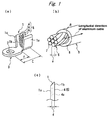
- a crimp contact of the present invention has a crimping portion 1 having a U-shaped cross-section (open barrel type), and a fastening portion 3 in which a bolt hole 2 is provided.
- a serration 5 including three parallel grooves 4 is formed in an inner face of the crimping portion 1.
- a sheath 8 of an cable end (being stripped insulation layer) of an aluminum cable 9 is removed, the thus-naked aluminum stranded wire 6 is inserted into the crimping portion 1, and side walls 1 a of the crimping portion 1 are pressed from the outside, so as to make a terminal structure of the aluminum stranded wire.
- C represents a distance from the center of the bolt hole 2 to the rear end of the crimping portion 1
- F represents a distance from the center of the bolt hole to the front end of the crimping portion
- (C - F) represents a length of the crimping portion 1.
- the ratio (d/e) between the depth d (see Fig. 1(c) ) of the grooves 4 and the diameter e (see Fig. 1(b) ) of the aluminum wires 7 which constitute the aluminum stranded wire 6, is set to 0.33 or more, and the number of grooves is set to 3 or more.
- the reason why the ratio (d/e) between the depth d of the grooves 4 of the serration 5 and the diameter e of the aluminum wires 7 which constitute the aluminum stranded wire 6, is set to 0.33 or more, and the number of grooves 4 is set to 3 or more, is that if the ratio (d/e) is less than 0.33 or if the number of grooves 4 of the serration 5 is less than 3, good electric connectivity cannot be stably attained.
- the number of grooves 4 of the serration 5 is preferably 5 or more, and the upper limit thereof is preferably 10. If it is too large, it is a possibility that a problem is caused in precision of the working and abrasion of stamping dies.
- the ratio (d/e) is preferably 0.5 or more, and the upper limit thereof is preferably 10. If it is too large, the oxide film is insufficiently broken so that a worry may be caused in the initial contact resistance or the stability during thermal shock.
- the depth of the grooves 4 of the serration 5 means the distance d from the inner face 1 b of the crimping portion 1 to bottom faces 4a of the grooves 4 (see Fig. 1 (c) ).
- the longitudinal direction of the grooves of the serration in the inner face of the crimping portion is generally made perpendicular to the longitudinal direction of the aluminum cable 9. That direction may be changed, according to the stranded angle b (see Fig. 1(b) ) of the aluminum stranded wire to the longitudinal direction of the aluminum cable (the arrow in Fig. 1 (b) ), whereby the connection strength and the like can be enhanced.
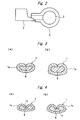
- the crimp contact illustrated in Fig. 2 is a crimp contact to be fastened to a battery terminal.
- the diameter of a hole 2 in a fastening portion 3 is slightly larger than the diameter of the battery terminal.
- the opening direction of a crimping portion 1 is perpendicular to the direction along which the hole 2 is made in the fastening portion 3.
- those two directions are parallel to each other.
- the crimp contact of the present invention can be formed from a sheet made of an electrically conductive metal, such as copper, a copper alloy, aluminum, or an aluminum alloy, and is preferably made of copper or a copper alloy, which is excellent in electrical conductivity and mechanical strength.
- the stress relaxation ratio of the crimping portion is preferably 70% or less, in order to prevent an increase in the electric resistance between the crimping portion and the aluminum stranded wire in cooling-and-heating cycles when using.
- the connection strength between the crimp contact and the aluminum stranded wire becomes high, which is preferable.
- the crystal grain size is more preferably 30 ⁇ m or less, even more preferably 20 ⁇ m or less.
- the crimp contact can be produced by integrally forming the sheet made of an electrically conductive metal.
- the crimp contact may also be produced by cutting an electrically conductive metal block.
- the electrical conductivity of this crimp contact is preferably 25%IACS or more, from the viewpoint of electrical conductivity. Further, it is preferred that the tensile strength of the crimp contact is 400 MPa or more and the Vickers hardness thereof is 90 N/mm 2 or more, since the connection strength between the crimp contact and the aluminum stranded wire becomes high.
- the tensile strength of the crimping portion is twice or more bigger than the tensile strength of the elemental wires of the aluminum stranded wire and the hardness thereof is twice or more bigger than the hardness of the elemental wires of the aluminum stranded wire since a newly generated face easily makes its appearance during crimping the stranded wire, so that the electric resistance between the contact and the aluminum wires of the stranded wire becomes stably low.
- the tin plating or tin alloy solder plating is applied at least to the surface of the serration portion in the crimp contact.
- the thickness thereof is preferably 1 ⁇ m or more.
- the application of the tin plating or solder plating makes the adhesiveness between the contact and the aluminum wires high when the stranded wire is crimped, so that the electric resistance becomes stably low. If the thickness is too large, the aluminum wires are less-fitted into the serration at the time of the crimping.
- the thickness is preferably 20 ⁇ m or less.
- the Cu plating or Ni plating is applied as the underlying plating for the Sn plating or solder plating, and further these are alternately plated layer by layer so as to be each made in one or more layers.
- the thickness of a pure Sn layer is preferably set to 0.2 ⁇ m or more, to keep corrosion resistance.
- the Cu plating is applied as the underlying plating for the Sn plating applied to the surface of the crimp contact for an aluminum stranded wire, and further the Ni plating is applied as the underlying plating for the copper layer.
- the cable end structure is a structure obtained by inserting the aluminum stranded wire 6 made naked by removing the sheath 8 of the end of the aluminum cable 9 illustrated in Fig. 1(b) , into the crimping portion 1 of the crimp contact illustrated in Fig. 1(a) , and then pressing the side walls 1 a of the crimping portion 1 from the outside to crimp the aluminum stranded wire 6 to the crimping portion 1.
- Fig. 3(a) and Fig. 3(b) each illustrate a cross section of the cable end structure.
- FIG. 3(a) illustrates the case where the ratio (p/q) between the sectional areas before and after the crimping of the aluminum stranded wire 6 is 0.7
- Fig. 3(b) illustrates the case where the ratio (p/q) between the sectional areas before and after the crimping of the aluminum stranded wire 6 is 0.95, in which p is the sectional area of the aluminum stranded wire after the crimping thereof, and q is the sectional area thereof before the crimping.
- FIG. 4(b) are each a structure in which front tip ends 1 c of side walls of a crimping portion 1 are embedded in the aluminum stranded wire 6 to increase the contact area between the aluminum stranded wire 6 and the crimping portion 1, and further an oxide film of the aluminum stranded wire 6 (aluminum wires 7) is broken in the side wall front tip ends 1 c to improve the electric connectivity.
- Fig. 4(a) illustrates a structure in which the ratio between the sectional areas is 0.7
- Fig. 4(b) illustrates a structure in which the ratio between the sectional areas is 0.95.
- the reason why the ratio (p/q) between the sectional area p of the aluminum stranded wire after crimping and the sectional area q thereof before the crimping is specified into the range of 0.7 to 0.95 is that: if the ratio p/q is too small, the stranded wire (elemental wires) is broken away or becomes too thin, not to give a sufficient connection strength between the crimp contact and the stranded wire, and the stranded wire undergoes work-hardening so that stress relaxation during cooling-and-heating cycles when using becomes large to increase the contact resistance; on the other hand, if the ratio p/q is too large, the crimping power becomes so weak that the oxide film of the aluminum stranded wire is not broken, whereby the initial contact resistance may increase, or so that the stranded wire may come out.
- the thickness of the oxide film on the surface of the aluminum wires 7, which constitute the aluminum stranded wire is preferred to have the thickness of the oxide film on the surface of the aluminum wires 7, which constitute the aluminum stranded wire, to 20 nm or less, since the connection strength between the crimp contact and the stranded wire can be made high within a compression ratio range from 0.7 to 0.95.
- Examples of the crimp contact of the present invention include crimp contacts each composed of a single crimping portion 1 and a single fastening portion 3, as illustrated in Fig. 1(a) and Fig. 2 , and crimp contacts for relaying, and crimp contacts for branching that are each composed of a plurality of crimping portions. Even if a single aluminum wire other than the stranded aluminum wire is used, the crimp contact of the present invention exhibits the same advantageous effects as in the case of using the aluminum stranded wire.
- a waterproof tube or waterproof mold is preferably applied to the outside of the wire, not to cause water to remain in a connection portion between the aluminum stranded wire and the contact, or the gaps between elemental wires of the aluminum stranded wire.
- the crimp contact of the present invention is a contact in which the depth of grooves of a serration in an inner face of a crimping portion is specified according to the diameter of aluminum wires which constitute aluminum stranded wire to be crimped. Therefore, at the time of crimping the stranded wire, an oxide film on the surface of the aluminum wires is sufficiently broken by the grooves, to favorable good electric connectivity. Further, the aluminum stranded wire can be prevented from coming out from the crimping portion, so that the mechanical connectivity is also excellent. The electric connectivity can be further enhanced, by making the crimping portion of copper or a copper alloy, setting the stress relaxation ratio of the crimping portion into a specific range, and/or applying plating thereto.
- the present invention in which the tensile strength and/or the Vickers hardness of the crimp contact are specified, exhibits a further-enhanced favorable electric connectivity.
- the ratio (p/q) between the sectional area p of the aluminum stranded wire after the crimping thereof and the sectional area q before the crimping is set into a specific range, favorable electric connectivity can be obtained. Further, the aluminum stranded wire is less damaged, and a sufficient connection strength can be given.
- Crimp contacts having a shape illustrated in Fig. 1(a) were each formed by pressing a Cu-30 mass% Zn alloy strip (O-material) 2.0 mm in thickness.
- a crimping portion 1 thereof was inserted an aluminum stranded wire 6 made naked by removing a sheath 8 of an end of aluminum cable 9 as illustrated in Fig. 1(b) .
- two side walls 1 a of the crimping portion 1 were pressed from the outside to crimp the aluminum stranded wire 6, thereby forming a cable end structure of the aluminum stranded wire.
- the length of the crimping portion 1, (C-F) in Fig. 1(a) was 13 mm.
- the aluminum stranded wire 6 to be used was a stranded wire having a sectional area of 25 mm 2 and made by stranding Al-0.1 mass%Mg-0.2mass%Cu alloy elemental wires, which each had a diameter of 0.32 mm and were annealed at 350°C for 2 hours, into a rope lay strand (19 groups/17 elemental wires) (i.e. a stranded wire obtained by: gathering 17 alloy elemental wires into each group; stranding each of the groups into a strand, and then standing the resultant strands, the number of which was 19, concentrically with each other).
- the number of grooves 4 in the inner face 1 b of the crimping portion 1 As shown in Table 1, for the individual sample, the following were variously changed: the number of grooves 4 in the inner face 1 b of the crimping portion 1; the ratio (d/e) between the depth d of the grooves 4 and the diameter e of the aluminum wires 7; and the ratio (p/q) between the sectional areas before and after the crimping of the aluminum stranded wire 6.
- connection strength pulse-out load
- the fastening portion and the aluminum cable were grasped to conduct a tensile test, and the load when the aluminum stranded wire came out from the crimping portion was determined.
- Crimp contacts in which the load was 1.7 kN or more were judged to be good in mechanical connectivity.
- the electric resistance of each of the cable end structures of the aluminum stranded wire was measured before and after a thermal impact test (cold-and-hot impact test).
- the following cable end structures were judged to be good in electric connectivity: structures in which the electric resistance r of the crimping portion before the test (initial stage) was 1.0 m ⁇ or less, the electric resistance s after the test (final stage) was 1.5 m ⁇ or less, and the ratio (s/r) between the electric resistances before and after the test was 10 or less.
- the thermal impact test was conducted by repeating a low-temperature environment of -40°C and a high-temperature environment of +120°C alternately to the crimping portion 1,000 times. The electric resistance was measured by a four-probe method.
- a current was caused to flow at 0.1 mA or more.
- the power source device to be used was a device having precision of a voltage of 0.1 V or less and a current of 0.01 A or less.
- the voltmeter to be used was a voltmeter having precision of 0.01 mV or less.
- the stress relaxation ratio of the crimping portion was measured under conditions that the surface maximum stress was 500 N/mm 2 , the temperature was 120°C, and the time period was 100 hours, which are prescribed in Japan Copper and Brass Association (JCBA) T312:2001.
- the stress relaxation ratio of the crimping portions of the crimp contacts was 50%. The results of these tests and measurements are shown in Table 1.
- a cable end structure of an aluminum stranded wire was formed in the same manner as in Example 1, except that the crimp contact was formed by using a Cu-30mass%Zn alloy strip (H-material) with thickness 2.3 mm. The same tests and measurements as in Example 1 were then conducted. The results are shown in Table 1.
- a cable end structure of an aluminum stranded wire was formed in the same manner as in Example 1, except that the crimp contact was formed by using a C5210 alloy strip (H-material) with thickness 1.7 mm. The same tests and measurements as in Example 1 were then conducted. The results are shown in Table 1.
- a cable end structure of an aluminum stranded wire was formed in the same manner as in Example 1, except that the crimp contact was formed by using a C1020 copper alloy strip (H-material) with thickness 2.0 mm and that the stress relaxation ratio of the crimping portion was set to a value outside the value range as specified in the above-mentioned item (2). The same tests and measurements as in Example 1 were then conducted. The results are shown in Table 1.
- Cable end structures of aluminum stranded wires were formed in the same manner as in Example 1, except that the ratio (p/q) between the sectional areas of the aluminum stranded wire before and after the crimping thereof was set to a value outside the value range as specified in the above-mentioned item (11). The same tests and measurements as in Example 1 were then conducted. The results are shown in Table 1.
- Cable end structures of aluminum stranded wires were formed in the same manner as in Example 1, except that the number of grooves of the serration or the ratio (d/e) between the groove depth d and the aluminum wire diameter e was set to a value outside the value range as specified in the above-mentioned item (1). The same tests and measurements as in Example 1 were then conducted. The results are shown in Table 1.
- each of the cable end structures of the aluminum stranded wires in the examples according to the present invention was high in pulling-out load, and low in electric resistance.
- the structures were excellent in mechanical connectivity and electric connectivity.
- Quite excellent in the above-mentioned connectivities were, in particular, the samples satisfying that the stress relaxation ratio of the crimping portion was 70% or less and the ratio (p/q) between the sectional areas of the aluminum stranded wire before and after the crimping was from 0.7 to 0.95 (Samples No. 1 to No. 9).
- the mechanical connectivity and electric connectivity were poor, since the number of grooves was small in the sample No. 13, and the ratio (d/e) between the groove depth and the aluminum wire diameter was small in the sample No. 14.
- Aluminum crimp contacts were formed from the same material in the same manner as in Example 1, except that alloy strips to which Sn plating was applied to give a thickness of 0.5 ⁇ m, 1.2 ⁇ m, 18 ⁇ m, and 24 ⁇ m, respectively, were used, and then cable end structures of aluminum stranded wire (samples No. 15 to No. 18) were formed in the same manner as in Example 1. The same tests and measurements as in Example 1 were then conducted. The number of grooves in the serration was set to 3, the groove depth was set to 0.11 mm, and the groove width was set to 1 mm, respectively. The ratio between the sectional areas before and after the crimping was set to 0.95.
- the Sn plating thickness was determined, by measuring the strength of fluorescent X-ray of 0.1 mm in collimator diameter at five points in the plating, and then averaging the measured values.
- Table 2 For reference, those of sample No. 5 in the Example 1, in which the ratio between the sectional areas before and after the crimping was 0.95, are also shown in Table 2.
- each of the cable end structures of aluminum stranded wires in which the Sn plating had a thickness in the range of 1.0 to 20 ⁇ m (inclusive) was low in electric resistance.
- the pulling-out strength in each of samples No. 15 to No. 18 was 2.4 kN, which was in the same level as that of the case to which no plating was applied (sample No. 5).
- the examples according to the present invention were excellent in mechanical connectivity and electric connectivity.
- Cable end structures of aluminum stranded wires were formed in the same manner as in Example 1, except that the tensile strength (TS) and the Vickers hardness (Hv) of the crimp contact were variously changed. The same tests and measurements as in Example 1 were then conducted.
- the number of grooves in the serration was set to 3, the groove depth was set to 0.11 mm, and the groove width was set to 1 mm, respectively.
- the ratio between the sectional areas before and after the crimping was set to 0.95.
- test pieces prescribed in JIS Z2201 were prepared from the strips before the strips were pressed, and the tensile strength was tested in accordance with a test method prescribed in JIS Z2241.
- the Vickers hardness test was conducted in accordance with JIS Z2244. The thus-obtained results are shown in Table 3.
- each of the samples satisfied the preferable regulations of electric resistance.
- the tensile strength of the contact material was 400 MPa or more
- the Vickers hardness was 90 or more
- the ratio between the tensile strengths and the ratio between the Vickers hardnesses were each 2 or more
- the cable end structure of the aluminum stranded wire was low in electric resistance and was also stable after the deterioration test.
- the pulling-out strength was 2.4 kN in each of samples No. 19 and No. 20.
- Cable end structures of aluminum stranded wires were formed in the same manner as in Example 1, except that the thickness of the oxide film of the aluminum wires constituting the aluminum stranded wire to be crimped was set to 5 nm, 20 nm, and 25 nm, respectively. The same tests and measurements as in Example 1 were then conducted. The number of grooves in the serration was set to 3, the groove depth was set to 0.11 mm, and the groove width was set to 1 mm, respectively. The ratio between the sectional areas before and after the crimping was set to 0.95. The thickness of the oxide film was controlled by heating of the aluminum stranded wire in the atmosphere.
- the oxide film on the surface of the aluminum stranded wire a region 10- ⁇ m square therein was measured by the Auger electron spectrometry.
- the aluminum wires were continuously chiseled from their surfaces by an argon ion gun capable of sputtering SiO 2 having a thickness of 100 nm for 10 minutes, and were subjected to spectrometry at each interval. From the sputtering period of time required to chisel until the percent by mass of oxygen turned to a half of that in the outermost surface, the thickness of the oxide film was determined by calculation, using the sputtering rate (4 nm/minute) of Al 2 O 3 . The thus-obtained results are shown in Table 4.
- the samples (No. 21 to No. 22) each satisfied the preferable regulations of electric resistance.
- the oxide film of the aluminum wires was 20 nm or less in thickness
- the cable end structures of aluminum stranded wires were low in electric resistance and were also stable after the deterioration test.
- the pulling-out strength was 2.4 kN in each of the samples (No. 21 to No. 22).
- the crimp contact for an aluminum stranded wire, of the present invention is excellent in electric connectivity and mechanical connectivity, and can favorably be used, for example, as a crimp contact for electric connection of automobile wire harnesses, battery cables, or the like, using an aluminum stranded wire.
Landscapes
- Conductive Materials (AREA)
- Connections Effected By Soldering, Adhesion, Or Permanent Deformation (AREA)
Abstract
Description
- The present invention relates to a crimp contact favorable for electric connection of automobile wire harnesses, battery cables, or the like, using an aluminum stranded wire, and to a cable end structure of an aluminum stranded wire excellent in electric connectivity, using the crimp contact.
- Aluminum stranded wires, which have electric conductor wires composed of an aluminum-based material, are used as a cable. In order that such cables are connected to various electric instruments or are connected to each other, a connection terminal is equipped at both ends of aluminum stranded wire. As the connection contact, a contact of a crimp contact-type is used.
As illustrated inFig. 5 , the crimp contact has a crimpingportion 10 of a U-shaped cross-section and a bolt-fastening portion 13, and aserration 12 is provided in the inner face of the crimpingportion 10, theserration 12 being formed of a plurality of concave grooves 11 for preventing the aluminum stranded wire from coming out. Ahole 14, in which a bolt or the like will be pierced, is formed in the fasteningportion 13. - An aluminum stranded wire (not illustrated) made naked by stripping a sheath of an aluminum cable terminal is inserted into the crimping
portion 10, andside walls 15 of the crimpingportion 10 are pressed from the outside, so as to crimp the portion and the wire to each other. Aluminum wires which constitute the aluminum stranded wire are fitted into the grooves 11 of theserration 12 by the crimping, so as to be prevented from coming out. Additionally, an oxide film of the aluminum wires, which constitute the aluminum stranded wire, is broken so that the metal which is inside the oxide film has exposed. Thus, good electric connection is attained. - Various improvements in connectivity between the aluminum stranded wire and the crimp contact have been proposed.
Examples thereof include: a structure in which powder of a metal, which is softer than the aluminum stranded wire, is dispersed in an inner face of a crimping portion to coagulate (adhere) the crimping portion inner face with the aluminum stranded wire; a structure in which a powder, which is harder than the aluminum stranded wire, is dispersed to break an oxide film on the surface of aluminum wires; a structure in which powders of the above softer one and harder one are dispersed; a structure in which fitting depths of serrations (grooves) are made different from each other; a structure in which a serration (groove) is formed into a spiral form; and a structure in which protrusions are formed on the inner face of a crimping portion.
However, the structures in which metal powder is dispersed or adhered have such a problem that costs and labors are required, and the above-mentioned groove structure and protrusion-formed serration form have such a problem that aging deterioration in contact resistance cannot be sufficiently prevented. - The present invention is contemplated for providing a crimp contact for an aluminum stranded wire, which makes it possible to prevent aging deterioration in electric connectivity, and for providing a cable end structure of an aluminum stranded wire to which the crimp contact is crimped, the structure being excellent in electric connectivity and mechanical connectivity, each of which can be attained without costs and labors.
- According to the present invention, there is provided the following means:
- (1) A crimp contact for an aluminum stranded wire having a serration provided in an inner face of a crimping portion of the crimp contact, wherein a ratio d/e is 0.33 or more, in which d represents a depth of a groove constituting the serration and e represents a diameter of an aluminum wire constituting the aluminum stranded wire, and wherein the number of grooves is 3 or more;
- (2) The crimp contact for an aluminum stranded wire according to item (1), wherein the crimping portion is composed of copper or a copper alloy, and wherein a stress relaxation ratio of the crimping portion is 70% or less;
- (3) The crimp contact for an aluminum stranded wire according to item (1) or (2), which is composed of brass having a crystal grain size of 50 µm or less;
- (4) The crimp contact for an aluminum stranded wire according to any one of items (1) to (3), which has an electrical conductivity of 25%IACS or more;
- (5) The crimp contact for an aluminum stranded wire according to any one of items (1) to (4), which has a tensile strength of 400 MPa or more, and a Vickers hardness of 90 N/mm2 or more;
- (6) The crimp contact for an aluminum stranded wire according to any one of items (1) to (5), which has the tensile strength twice or more bigger than a tensile strength of the elemental wires which constitute the aluminum stranded wire, and has the Vickers hardness twice or more bigger than a hardness of the elemental wires which constitute the aluminum stranded wire;
- (7) The crimp contact for an aluminum stranded wire according to any one of items (1) to (6), which has a surface to which a tin (Sn) plating or solder plating is applied so as to have a thickness of 1 µm or more and 20 µm or less;
- (8) The crimp contact for an aluminum stranded wire according to item (7), wherein the Sn plating has a pure Sn layer having a thickness of 0.2 µm or more;
- (9) The crimp contact for an aluminum stranded wire according to item (7) or (8), to which a copper (Cu) plating or a nickel (Ni) plating is applied as an underlying plating for the Sn plating or the solder plating;
- (10) The crimp contact for an aluminum stranded wire according to any one of items (7) to (9), to which a Cu plating is applied as an underlying plating for the Sn plating, and a Ni plating is applied as an underlying plating for the Cu plating;
- (11) A cable end structure of an aluminum stranded wire to which the crimp contact for an aluminum stranded wire according to any one of items (1) to (10) is crimped, wherein a ratio p/q is from 0.7 to 0.95, in which p represents a sectional area of the aluminum stranded wire after the crimping and q represents a sectional area of the aluminum stranded wire before the crimping; and
- (12) The cable end structure of an aluminum stranded wire according to item (11), wherein a thickness of an oxide film of the aluminum wires which constitute the aluminum stranded wire is 20 nm or less.
- Other and further features and advantages of the invention will appear more fully from the following description, appropriately referring to the accompanying drawings.
-
- [
Fig. 1 ]
Figs. 1(a) to 1(c) are explanatory views illustrating an embodiment of the crimp contact of the present invention for an aluminum stranded wire, andFig. 1(a) is a perspective view of the crimp contact,Fig. 1(b) is a perspective view of an aluminum cable having a cable end being stripped the sheath, andFig. 1(c) is an explanatory view of grooves of a serration. - [
Fig. 2 ]
Fig. 2 is a front view illustrating another embodiment of the crimp contact of the present invention for an aluminum stranded wire. - [
Fig. 3 ]
Fig. 3(a) and Fig. 3(b) are each a sectional view illustrating an embodiment of the cable end structure of the present invention of an aluminum stranded wire, andFig. 3(a) illustrates a structure in which the ratio between sectional areas is 0.7, andFig. 3(b) illustrates a structure in which the ratio between sectional areas is 0.95. - [
Fig. 4 ]
Fig. 4(a) and Fig. 4(b) are each a sectional view illustrating another embodiment of the cable end structure of the present invention of an aluminum stranded wire, andFig. 4(a) illustrates a structure in which the ratio between sectional areas is 0.7, andFig. 4(b) illustrates a structure in which the ratio between sectional areas is 0.95. - [
Fig. 5 ]
Fig. 5 is a perspective view of a conventional crimp contact for an aluminum stranded wire. - With reference to the drawings, preferred embodiments of the crimp contact of the present invention for an aluminum stranded wire will be specifically described hereinafter.
As illustrated inFig. 1(a) , a crimp contact of the present invention has a crimpingportion 1 having a U-shaped cross-section (open barrel type), and afastening portion 3 in which abolt hole 2 is provided. Aserration 5 including threeparallel grooves 4 is formed in an inner face of the crimpingportion 1. As illustrated inFig. 1(b) , for example, asheath 8 of an cable end (being stripped insulation layer) of analuminum cable 9 is removed, the thus-naked aluminum strandedwire 6 is inserted into the crimpingportion 1, andside walls 1 a of the crimpingportion 1 are pressed from the outside, so as to make a terminal structure of the aluminum stranded wire.
InFig. 1(a) , C represents a distance from the center of thebolt hole 2 to the rear end of the crimpingportion 1, F represents a distance from the center of the bolt hole to the front end of thecrimping portion 1, and (C - F) represents a length of thecrimping portion 1. - In the present invention, the ratio (d/e) between the depth d (see
Fig. 1(c) ) of thegrooves 4 and the diameter e (seeFig. 1(b) ) of the aluminum wires 7 which constitute the aluminum strandedwire 6, is set to 0.33 or more, and the number of grooves is set to 3 or more.
In the present invention, the reason why the ratio (d/e) between the depth d of thegrooves 4 of theserration 5 and the diameter e of the aluminum wires 7 which constitute the aluminum strandedwire 6, is set to 0.33 or more, and the number ofgrooves 4 is set to 3 or more, is that if the ratio (d/e) is less than 0.33 or if the number ofgrooves 4 of theserration 5 is less than 3, good electric connectivity cannot be stably attained.
The number ofgrooves 4 of theserration 5 is preferably 5 or more, and the upper limit thereof is preferably 10. If it is too large, it is a possibility that a problem is caused in precision of the working and abrasion of stamping dies. The ratio (d/e) is preferably 0.5 or more, and the upper limit thereof is preferably 10. If it is too large, the oxide film is insufficiently broken so that a worry may be caused in the initial contact resistance or the stability during thermal shock. The depth of thegrooves 4 of theserration 5 means the distance d from theinner face 1 b of the crimpingportion 1 tobottom faces 4a of the grooves 4 (seeFig. 1 (c) ). - In the present invention, the longitudinal direction of the grooves of the serration in the inner face of the crimping portion is generally made perpendicular to the longitudinal direction of the
aluminum cable 9. That direction may be changed, according to the stranded angle b (seeFig. 1(b) ) of the aluminum stranded wire to the longitudinal direction of the aluminum cable (the arrow inFig. 1 (b) ), whereby the connection strength and the like can be enhanced. - The crimp contact illustrated in
Fig. 2 is a crimp contact to be fastened to a battery terminal. The diameter of ahole 2 in afastening portion 3 is slightly larger than the diameter of the battery terminal. In this crimp contact, the opening direction of a crimpingportion 1 is perpendicular to the direction along which thehole 2 is made in thefastening portion 3. In the crimp contact illustrated inFig. 1(a) , those two directions are parallel to each other. - The crimp contact of the present invention can be formed from a sheet made of an electrically conductive metal, such as copper, a copper alloy, aluminum, or an aluminum alloy, and is preferably made of copper or a copper alloy, which is excellent in electrical conductivity and mechanical strength. The stress relaxation ratio of the crimping portion is preferably 70% or less, in order to prevent an increase in the electric resistance between the crimping portion and the aluminum stranded wire in cooling-and-heating cycles when using.
In particular, in the case of using brass having a crystal grain size of 50 µm or less as the material of the crimp contact, the connection strength between the crimp contact and the aluminum stranded wire becomes high, which is preferable. The crystal grain size is more preferably 30 µm or less, even more preferably 20 µm or less.
The crimp contact can be produced by integrally forming the sheet made of an electrically conductive metal. The crimp contact may also be produced by cutting an electrically conductive metal block. - The electrical conductivity of this crimp contact is preferably 25%IACS or more, from the viewpoint of electrical conductivity.
Further, it is preferred that the tensile strength of the crimp contact is 400 MPa or more and the Vickers hardness thereof is 90 N/mm2 or more, since the connection strength between the crimp contact and the aluminum stranded wire becomes high. It is preferred that the tensile strength of the crimping portion is twice or more bigger than the tensile strength of the elemental wires of the aluminum stranded wire and the hardness thereof is twice or more bigger than the hardness of the elemental wires of the aluminum stranded wire since a newly generated face easily makes its appearance during crimping the stranded wire, so that the electric resistance between the contact and the aluminum wires of the stranded wire becomes stably low. - In the present invention, it is preferred that the tin plating or tin alloy solder plating is applied at least to the surface of the serration portion in the crimp contact. The thickness thereof is preferably 1 µm or more. The application of the tin plating or solder plating makes the adhesiveness between the contact and the aluminum wires high when the stranded wire is crimped, so that the electric resistance becomes stably low. If the thickness is too large, the aluminum wires are less-fitted into the serration at the time of the crimping. Thus, the thickness is preferably 20 µm or less. Furthermore, in order to prevent an increase in the electric resistance between the crimping portion and the aluminum stranded wire in cooling-and-heating cycles when using, it is preferred that the Cu plating or Ni plating is applied as the underlying plating for the Sn plating or solder plating, and further these are alternately plated layer by layer so as to be each made in one or more layers. In the case of the Sn plating, the thickness of a pure Sn layer is preferably set to 0.2 µm or more, to keep corrosion resistance.
- In another embodiment of the present invention, it is preferable that the Cu plating is applied as the underlying plating for the Sn plating applied to the surface of the crimp contact for an aluminum stranded wire, and further the Ni plating is applied as the underlying plating for the copper layer.
- The following will describe the cable end structure, of the present invention, of an aluminum stranded wire.
The cable end structure is a structure obtained by inserting the aluminum strandedwire 6 made naked by removing thesheath 8 of the end of thealuminum cable 9 illustrated inFig. 1(b) , into the crimpingportion 1 of the crimp contact illustrated inFig. 1(a) , and then pressing theside walls 1 a of the crimpingportion 1 from the outside to crimp the aluminum strandedwire 6 to the crimpingportion 1.Fig. 3(a) and Fig. 3(b) each illustrate a cross section of the cable end structure.Fig. 3(a) illustrates the case where the ratio (p/q) between the sectional areas before and after the crimping of the aluminum strandedwire 6 is 0.7, andFig. 3(b) illustrates the case where the ratio (p/q) between the sectional areas before and after the crimping of the aluminum strandedwire 6 is 0.95, in which p is the sectional area of the aluminum stranded wire after the crimping thereof, and q is the sectional area thereof before the crimping.
Cable end structures illustrated inFig. 4(a) and Fig. 4(b) are each a structure in which front tip ends 1 c of side walls of a crimpingportion 1 are embedded in the aluminum strandedwire 6 to increase the contact area between the aluminum strandedwire 6 and the crimpingportion 1, and further an oxide film of the aluminum stranded wire 6 (aluminum wires 7) is broken in the side wall front tip ends 1 c to improve the electric connectivity.Fig. 4(a) illustrates a structure in which the ratio between the sectional areas is 0.7, andFig. 4(b) illustrates a structure in which the ratio between the sectional areas is 0.95. - In the present invention, the reason why the ratio (p/q) between the sectional area p of the aluminum stranded wire after crimping and the sectional area q thereof before the crimping is specified into the range of 0.7 to 0.95 is that: if the ratio p/q is too small, the stranded wire (elemental wires) is broken away or becomes too thin, not to give a sufficient connection strength between the crimp contact and the stranded wire, and the stranded wire undergoes work-hardening so that stress relaxation during cooling-and-heating cycles when using becomes large to increase the contact resistance; on the other hand, if the ratio p/q is too large, the crimping power becomes so weak that the oxide film of the aluminum stranded wire is not broken, whereby the initial contact resistance may increase, or so that the stranded wire may come out.
- It is preferred to have the thickness of the oxide film on the surface of the aluminum wires 7, which constitute the aluminum stranded wire, to 20 nm or less, since the connection strength between the crimp contact and the stranded wire can be made high within a compression ratio range from 0.7 to 0.95.
- Examples of the crimp contact of the present invention include crimp contacts each composed of a single crimping
portion 1 and asingle fastening portion 3, as illustrated inFig. 1(a) andFig. 2 , and crimp contacts for relaying, and crimp contacts for branching that are each composed of a plurality of crimping portions. Even if a single aluminum wire other than the stranded aluminum wire is used, the crimp contact of the present invention exhibits the same advantageous effects as in the case of using the aluminum stranded wire. - In the cable end structure of an aluminum stranded wire, to which the crimp contact of the present invention for an aluminum stranded wire is crimped, in order to prevent corrosion between different metals or prevent corrosion of gaps between the aluminum stranded wire, a waterproof tube or waterproof mold is preferably applied to the outside of the wire, not to cause water to remain in a connection portion between the aluminum stranded wire and the contact, or the gaps between elemental wires of the aluminum stranded wire.
The present invention is not limited to the above-mentioned embodiments, and any variation thereof may be carried out as long as the variation does not depart from the subject matter of the present invention. - The crimp contact of the present invention is a contact in which the depth of grooves of a serration in an inner face of a crimping portion is specified according to the diameter of aluminum wires which constitute aluminum stranded wire to be crimped. Therefore, at the time of crimping the stranded wire, an oxide film on the surface of the aluminum wires is sufficiently broken by the grooves, to favorable good electric connectivity. Further, the aluminum stranded wire can be prevented from coming out from the crimping portion, so that the mechanical connectivity is also excellent. The electric connectivity can be further enhanced, by making the crimping portion of copper or a copper alloy, setting the stress relaxation ratio of the crimping portion into a specific range, and/or applying plating thereto. Additionally, the present invention in which the tensile strength and/or the Vickers hardness of the crimp contact are specified, exhibits a further-enhanced favorable electric connectivity.
In the cable end structure of an aluminum stranded wire, according to the present invention, since the ratio (p/q) between the sectional area p of the aluminum stranded wire after the crimping thereof and the sectional area q before the crimping is set into a specific range, favorable electric connectivity can be obtained. Further, the aluminum stranded wire is less damaged, and a sufficient connection strength can be given. - The present invention will be described in more detail based on examples given below, but the invention is not meant to be limited by these.
- Crimp contacts having a shape illustrated in
Fig. 1(a) were each formed by pressing a Cu-30 mass% Zn alloy strip (O-material) 2.0 mm in thickness. Into a crimpingportion 1 thereof, was inserted an aluminum strandedwire 6 made naked by removing asheath 8 of an end ofaluminum cable 9 as illustrated inFig. 1(b) . Then, twoside walls 1 a of the crimpingportion 1 were pressed from the outside to crimp the aluminum strandedwire 6, thereby forming a cable end structure of the aluminum stranded wire. The length of the crimpingportion 1, (C-F) inFig. 1(a) , was 13 mm.
The aluminum strandedwire 6 to be used was a stranded wire having a sectional area of 25 mm2 and made by stranding Al-0.1 mass%Mg-0.2mass%Cu alloy elemental wires, which each had a diameter of 0.32 mm and were annealed at 350°C for 2 hours, into a rope lay strand (19 groups/17 elemental wires) (i.e. a stranded wire obtained by: gathering 17 alloy elemental wires into each group; stranding each of the groups into a strand, and then standing the resultant strands, the number of which was 19, concentrically with each other). As shown in Table 1, for the individual sample, the following were variously changed: the number ofgrooves 4 in theinner face 1 b of the crimpingportion 1; the ratio (d/e) between the depth d of thegrooves 4 and the diameter e of the aluminum wires 7; and the ratio (p/q) between the sectional areas before and after the crimping of the aluminum strandedwire 6. - With respect to the resultant cable end structures of aluminum stranded wires, the connection strength (pulling-out load) between the aluminum stranded wire and the crimping portion, and the electric resistance were examined.
As for the connection strength of each of the crimp contacts, the fastening portion and the aluminum cable were grasped to conduct a tensile test, and the load when the aluminum stranded wire came out from the crimping portion was determined. Crimp contacts in which the load was 1.7 kN or more were judged to be good in mechanical connectivity. - The electric resistance of each of the cable end structures of the aluminum stranded wire was measured before and after a thermal impact test (cold-and-hot impact test). The following cable end structures were judged to be good in electric connectivity: structures in which the electric resistance r of the crimping portion before the test (initial stage) was 1.0 mΩ or less, the electric resistance s after the test (final stage) was 1.5 mΩ or less, and the ratio (s/r) between the electric resistances before and after the test was 10 or less.
The thermal impact test was conducted by repeating a low-temperature environment of -40°C and a high-temperature environment of +120°C alternately to the crimping portion 1,000 times.
The electric resistance was measured by a four-probe method. A current was caused to flow at 0.1 mA or more. The power source device to be used was a device having precision of a voltage of 0.1 V or less and a current of 0.01 A or less. The voltmeter to be used was a voltmeter having precision of 0.01 mV or less. - The stress relaxation ratio of the crimping portion was measured under conditions that the surface maximum stress was 500 N/mm2, the temperature was 120°C, and the time period was 100 hours, which are prescribed in Japan Copper and Brass Association (JCBA) T312:2001.
The stress relaxation ratio of the crimping portions of the crimp contacts was 50%.
The results of these tests and measurements are shown in Table 1. - A cable end structure of an aluminum stranded wire was formed in the same manner as in Example 1, except that the crimp contact was formed by using a Cu-30mass%Zn alloy strip (H-material) with thickness 2.3 mm. The same tests and measurements as in Example 1 were then conducted. The results are shown in Table 1.
- A cable end structure of an aluminum stranded wire was formed in the same manner as in Example 1, except that the crimp contact was formed by using a C5210 alloy strip (H-material) with thickness 1.7 mm. The same tests and measurements as in Example 1 were then conducted. The results are shown in Table 1.
- A cable end structure of an aluminum stranded wire was formed in the same manner as in Example 1, except that the crimp contact was formed by using a C1020 copper alloy strip (H-material) with thickness 2.0 mm and that the stress relaxation ratio of the crimping portion was set to a value outside the value range as specified in the above-mentioned item (2). The same tests and measurements as in Example 1 were then conducted. The results are shown in Table 1.
- Cable end structures of aluminum stranded wires were formed in the same manner as in Example 1, except that the ratio (p/q) between the sectional areas of the aluminum stranded wire before and after the crimping thereof was set to a value outside the value range as specified in the above-mentioned item (11). The same tests and measurements as in Example 1 were then conducted. The results are shown in Table 1.
- Cable end structures of aluminum stranded wires were formed in the same manner as in Example 1, except that the number of grooves of the serration or the ratio (d/e) between the groove depth d and the aluminum wire diameter e was set to a value outside the value range as specified in the above-mentioned item (1). The same tests and measurements as in Example 1 were then conducted. The results are shown in Table 1.
-

- As is evident from Table 1, each of the cable end structures of the aluminum stranded wires in the examples according to the present invention (Samples No. 1 to No. 12), was high in pulling-out load, and low in electric resistance. In short, the structures were excellent in mechanical connectivity and electric connectivity. Quite excellent in the above-mentioned connectivities were, in particular, the samples satisfying that the stress relaxation ratio of the crimping portion was 70% or less and the ratio (p/q) between the sectional areas of the aluminum stranded wire before and after the crimping was from 0.7 to 0.95 (Samples No. 1 to No. 9).
Contrary to the above, in each of Sample No. 13 and Sample No. 14 of Comparative Example 1, the mechanical connectivity and electric connectivity were poor, since the number of grooves was small in the sample No. 13, and the ratio (d/e) between the groove depth and the aluminum wire diameter was small in the sample No. 14. - Aluminum crimp contacts were formed from the same material in the same manner as in Example 1, except that alloy strips to which Sn plating was applied to give a thickness of 0.5 µm, 1.2 µm, 18 µm, and 24 µm, respectively, were used, and then cable end structures of aluminum stranded wire (samples No. 15 to No. 18) were formed in the same manner as in Example 1. The same tests and measurements as in Example 1 were then conducted.
The number of grooves in the serration was set to 3, the groove depth was set to 0.11 mm, and the groove width was set to 1 mm, respectively. The ratio between the sectional areas before and after the crimping was set to 0.95. The Sn plating thickness was determined, by measuring the strength of fluorescent X-ray of 0.1 mm in collimator diameter at five points in the plating, and then averaging the measured values.
The thus-obtained results are shown in Table 2. For reference, those of sample No. 5 in the Example 1, in which the ratio between the sectional areas before and after the crimping was 0.95, are also shown in Table 2. -
Table 2 Sample No. Sn plating Thickness (µm) Electric resistance (mΩ) Initial r Final s s/ r 15 Applied 0.5 1.0 1.1 1.1 16 1.2 0.5 0.5 1.0 17 18 0.5 0.5 1.0 18 24 1.0 1.1 1.1 5 Not applied 1.0 1.05 1.1 - As is evident from Table 2, each of the cable end structures of aluminum stranded wires in which the Sn plating had a thickness in the range of 1.0 to 20 µm (inclusive) was low in electric resistance. The pulling-out strength in each of samples No. 15 to No. 18 was 2.4 kN, which was in the same level as that of the case to which no plating was applied (sample No. 5). In short, the examples according to the present invention were excellent in mechanical connectivity and electric connectivity.
- Cable end structures of aluminum stranded wires (samples No. 19 to No. 20) were formed in the same manner as in Example 1, except that the tensile strength (TS) and the Vickers hardness (Hv) of the crimp contact were variously changed. The same tests and measurements as in Example 1 were then conducted. The number of grooves in the serration was set to 3, the groove depth was set to 0.11 mm, and the groove width was set to 1 mm, respectively. The ratio between the sectional areas before and after the crimping was set to 0.95.
As for the tensile strength of the crimp contacts, test pieces prescribed in JIS Z2201 were prepared from the strips before the strips were pressed, and the tensile strength was tested in accordance with a test method prescribed in JIS Z2241. The Vickers hardness test was conducted in accordance with JIS Z2244.
The thus-obtained results are shown in Table 3. -
Table 3 Sample No. Contact Aluminum wire Ratio of strength and hardness Electric resistance (mΩ) TS (MPa) Hv (N/mm2) TS (MPa) Hv (N/mm2) TS ratio Hv ratio Initial r Final s s/r 19 380 85 200 45 1.9 1.9 1.0 1.05 1.1 20 400 100 2.0 2.2 0.7 0.7 1.0 - As is evident from Table 3, each of the samples (Nos. 19 and 20) satisfied the preferable regulations of electric resistance. In particular, in the case where the tensile strength of the contact material was 400 MPa or more, the Vickers hardness was 90 or more, and the ratio between the tensile strengths and the ratio between the Vickers hardnesses (the ratio (that of the contact)/(the aluminum wires)) were each 2 or more, the cable end structure of the aluminum stranded wire was low in electric resistance and was also stable after the deterioration test. The pulling-out strength was 2.4 kN in each of samples No. 19 and No. 20.
- Cable end structures of aluminum stranded wires (samples No. 21 to No. 23) were formed in the same manner as in Example 1, except that the thickness of the oxide film of the aluminum wires constituting the aluminum stranded wire to be crimped was set to 5 nm, 20 nm, and 25 nm, respectively. The same tests and measurements as in Example 1 were then conducted. The number of grooves in the serration was set to 3, the groove depth was set to 0.11 mm, and the groove width was set to 1 mm, respectively. The ratio between the sectional areas before and after the crimping was set to 0.95. The thickness of the oxide film was controlled by heating of the aluminum stranded wire in the atmosphere.
About the oxide film on the surface of the aluminum stranded wire, a region 10-µm square therein was measured by the Auger electron spectrometry. The aluminum wires were continuously chiseled from their surfaces by an argon ion gun capable of sputtering SiO2 having a thickness of 100 nm for 10 minutes, and were subjected to spectrometry at each interval. From the sputtering period of time required to chisel until the percent by mass of oxygen turned to a half of that in the outermost surface, the thickness of the oxide film was determined by calculation, using the sputtering rate (4 nm/minute) of Al2O3.
The thus-obtained results are shown in Table 4. -
Table 4 Sample No. Thickness of oxide film (nm) Electric resistance (mΩ) Initial r Final s s/r 21 5 0.8 1.0 1.3 22 20 0.8 1.0 1.3 23 25 1.0 1.5 1.5 - As is evident from Table 4, the samples (No. 21 to No. 22) each satisfied the preferable regulations of electric resistance. When the oxide film of the aluminum wires was 20 nm or less in thickness, the cable end structures of aluminum stranded wires were low in electric resistance and were also stable after the deterioration test. The pulling-out strength was 2.4 kN in each of the samples (No. 21 to No. 22).
- The crimp contact for an aluminum stranded wire, of the present invention, is excellent in electric connectivity and mechanical connectivity, and can favorably be used, for example, as a crimp contact for electric connection of automobile wire harnesses, battery cables, or the like, using an aluminum stranded wire.
- Having described our invention as related to the present embodiments, it is our intention that the invention not be limited by any of the details of the description, unless otherwise specified, but rather be construed broadly within its spirit and scope as set out in the accompanying claims.
- This application claims priority on Patent Application No.
2005-338604 2006-293215
Claims (12)
- A crimp contact for an aluminum stranded wire having a serration provided in an inner face of a crimping portion of the crimp contact, wherein a ratio d/e is 0.33 or more, in which d represents a depth of a groove constituting the serration and e represents a diameter of an aluminum elemental wire constituting the aluminum stranded wire, and wherein the number of grooves is 3 or more.
- The crimp contact for an aluminum stranded wire according to Claim 1, wherein the crimping portion is composed of copper or a copper alloy, and wherein a stress relaxation ratio of the crimping portion is 70% or less.
- The crimp contact for an aluminum stranded wire according to Claim 1 or 2, which is composed of brass having a crystal grain size of 50 µm or less.
- The crimp contact for an aluminum stranded wire according to any one of Claims 1 to 3, which has an electrical conductivity of 25%IACS or more.
- The crimp contact for an aluminum stranded wire according to any one of Claims 1 to 4, which has a tensile strength of 400 MPa or more, and a Vickers hardness of 90 N/mm2 or more.
- The crimp contact for an aluminum stranded wire according to any one of Claims 1 to 5, which has the tensile strength twice or more bigger than a tensile strength of the elemental wires which constitute the aluminum stranded wire, and has the Vickers hardness twice or more bigger than a hardness of the elemental wires which constitute the aluminum stranded wire.
- The crimp contact for an aluminum stranded wire according to any one of Claims 1 to 6, which has a surface to which a Sn plating or a solder plating is applied so as to have a thickness of 1 µm or more and 20 µm or less.
- The crimp contact for an aluminum stranded wire according to Claim 7, wherein the Sn plating has a pure Sn layer having a thickness of 0.2 µm or more.
- The crimp contact for an aluminum stranded wire according to Claim 7 or 8, to which a Cu plating or a Ni plating is applied as an underlying plating for the Sn plating or the solder plating.
- The crimp contact for an aluminum stranded wire according to any one of Claims 7 to 9, to which a Cu plating is applied as an underlying plating for the Sn plating, and a Ni plating is applied as an underlying plating therefor.
- A terminal structure of an aluminum stranded wire to which the crimp contact for an aluminum stranded wire according to any one of Claims 1 to 10 is crimped, wherein a ratio p/q is from 0.7 to 0.95, in which p represents a sectional area of the aluminum stranded wire after the crimping and q represents a sectional area of the aluminum stranded wire before the crimping.
- The terminal structure of an aluminum stranded wire according to Claim 11, wherein a thickness of an oxide film of the aluminum elemental wires which constitute the aluminum stranded wire is 20 nm or less.
Applications Claiming Priority (3)
| Application Number | Priority Date | Filing Date | Title |
|---|---|---|---|
| JP2005338604 | 2005-11-24 | ||
| JP2006293215A JP4550791B2 (en) | 2005-11-24 | 2006-10-27 | Aluminum stranded wire crimp terminal and aluminum stranded wire terminal structure to which the crimp terminal is connected |
| PCT/JP2006/323232 WO2007060953A1 (en) | 2005-11-24 | 2006-11-21 | Crimp-style terminal for aluminum strand and terminal structure of aluminum strand having the crimp-style terminal connected thereto |
Publications (3)
| Publication Number | Publication Date |
|---|---|
| EP1965464A1 true EP1965464A1 (en) | 2008-09-03 |
| EP1965464A4 EP1965464A4 (en) | 2012-01-04 |
| EP1965464B1 EP1965464B1 (en) | 2016-03-09 |
Family
ID=38067179
Family Applications (1)
| Application Number | Title | Priority Date | Filing Date |
|---|---|---|---|
| EP06833078.6A Active EP1965464B1 (en) | 2005-11-24 | 2006-11-21 | Crimp-style terminal for aluminum strand and terminal structure of aluminum strand having the crimp-style terminal connected thereto |
Country Status (4)
| Country | Link |
|---|---|
| US (2) | US7544892B2 (en) |
| EP (1) | EP1965464B1 (en) |
| JP (1) | JP4550791B2 (en) |
| WO (1) | WO2007060953A1 (en) |
Cited By (8)
| Publication number | Priority date | Publication date | Assignee | Title |
|---|---|---|---|---|
| WO2009096591A1 (en) * | 2008-01-28 | 2009-08-06 | Yazaki Corporation | Crimp terminal |
| WO2009096590A1 (en) * | 2008-01-28 | 2009-08-06 | Yazaki Corporation | Crimp terminal |
| WO2010094005A1 (en) * | 2009-02-16 | 2010-08-19 | Tensolite Company | Terminal having integral oxide breaker |
| ITPD20120215A1 (en) * | 2012-07-05 | 2014-01-06 | Co Plast S R L Fa | FASTENER FOR SEALING CABLES FOR COVER SHEETS FOR OPENED CONTAINERS OF TRUCKS, TRUCKS AND SIMILAR |
| US9985362B2 (en) | 2015-10-22 | 2018-05-29 | Carlisle Interconnect Technologies, Inc. | Arc resistant power terminal |
| US10164348B2 (en) | 2009-02-16 | 2018-12-25 | Carlisle Interconnect Technologies, Inc. | Terminal/connector having integral oxide breaker element |
| EP3605739A4 (en) * | 2017-03-27 | 2020-12-30 | Furukawa Electric Co., Ltd. | Connection structure |
| US12470013B2 (en) | 2023-06-23 | 2025-11-11 | Amphenol Cable And Interconnect Technologies, Inc. | Electrical terminal connector with rotatable mounting features |
Families Citing this family (64)
| Publication number | Priority date | Publication date | Assignee | Title |
|---|---|---|---|---|
| JP2009009736A (en) * | 2007-06-26 | 2009-01-15 | Auto Network Gijutsu Kenkyusho:Kk | Terminal connection structure to aluminum wire |
| JP5078567B2 (en) | 2007-11-16 | 2012-11-21 | 矢崎総業株式会社 | Crimp terminal for aluminum wire |
| JP5219494B2 (en) * | 2007-12-20 | 2013-06-26 | 矢崎総業株式会社 | Plated terminal crimping method |
| JP5196535B2 (en) * | 2007-12-20 | 2013-05-15 | 矢崎総業株式会社 | Terminal crimping method for aluminum wires |
| CN101946368A (en) * | 2008-02-15 | 2011-01-12 | 株式会社自动网络技术研究所 | Terminal connector and bunch |
| JP5119533B2 (en) * | 2008-02-15 | 2013-01-16 | 矢崎総業株式会社 | Crimp terminal and crimp structure using this crimp terminal |
| JP5116512B2 (en) * | 2008-03-10 | 2013-01-09 | 矢崎総業株式会社 | Crimping method using crimp terminals |
| JP5027022B2 (en) * | 2008-03-19 | 2012-09-19 | 古河電気工業株式会社 | Crimp terminals and crimp terminal connectors |
| JP5249615B2 (en) | 2008-03-24 | 2013-07-31 | 矢崎総業株式会社 | Crimp terminal for aluminum wire |
| JP5065991B2 (en) * | 2008-05-16 | 2012-11-07 | 矢崎総業株式会社 | Crimp terminal for aluminum wire |
| JP5065993B2 (en) * | 2008-05-22 | 2012-11-07 | 矢崎総業株式会社 | Crimp terminal for aluminum wire |
| JP2010009789A (en) * | 2008-06-24 | 2010-01-14 | Autonetworks Technologies Ltd | Terminal metal fixture and wire with terminal |
| JP2010010000A (en) * | 2008-06-27 | 2010-01-14 | Autonetworks Technologies Ltd | Terminal metal fixture and wire with terminal |
| JP2010010001A (en) * | 2008-06-27 | 2010-01-14 | Autonetworks Technologies Ltd | Terminal metal fixture and wire with terminal |
| JP2010010086A (en) * | 2008-06-30 | 2010-01-14 | Autonetworks Technologies Ltd | Terminal metal fixture and wire with terminal |
| US7722416B2 (en) * | 2008-10-02 | 2010-05-25 | Delphi Technologies, Inc. | Electrical connection system for use on aluminum wires |
| JP5346607B2 (en) * | 2009-02-04 | 2013-11-20 | 日立電線株式会社 | Terminal and connection method of terminal and electric wire |
| KR20100090482A (en) * | 2009-02-06 | 2010-08-16 | 삼성전자주식회사 | Motor and washing machine having the same |
| JP5495200B2 (en) * | 2009-02-12 | 2014-05-21 | 矢崎総業株式会社 | Wire crimping device |
| JP2010198789A (en) * | 2009-02-23 | 2010-09-09 | Fujikura Ltd | Terminal structure of crimp terminal |
| JP5300136B2 (en) * | 2009-03-04 | 2013-09-25 | 矢崎総業株式会社 | Crimp terminal and crimp structure |
| US20110014825A1 (en) * | 2009-07-16 | 2011-01-20 | Delphi Technologies, Inc. | Electrical terminal connection with galvanic sacrificial metal |
| JP2011040194A (en) * | 2009-08-07 | 2011-02-24 | Autonetworks Technologies Ltd | Crimped electric wire with terminal and method for producing the same |
| US8360803B2 (en) * | 2009-09-18 | 2013-01-29 | Delphi Technologies, Inc. | Electrical terminal connection with molded seal |
| EP2498383B1 (en) * | 2009-11-06 | 2020-02-12 | Yazaki Corporation | Inverter terminal block provided to motor case |
| JP5458931B2 (en) * | 2010-02-15 | 2014-04-02 | 日立金属株式会社 | Electric wire with terminal |
| JP5660458B2 (en) * | 2010-02-16 | 2015-01-28 | 日立金属株式会社 | Electric wire with terminal and manufacturing method thereof |
| JP4790851B2 (en) * | 2010-03-11 | 2011-10-12 | 株式会社 ピー・エル | Aluminum body connection structure and connector |
| JP5564318B2 (en) | 2010-04-13 | 2014-07-30 | 矢崎総業株式会社 | Inspection method of conductor crimping part of crimping terminal |
| DE102010020346A1 (en) * | 2010-05-12 | 2011-11-17 | Harting Electric Gmbh & Co. Kg | Electrical contact element |
| JP5777861B2 (en) * | 2010-06-14 | 2015-09-09 | 古河電気工業株式会社 | Production method of wire harness and wire terminal anticorrosion structure |
| CN102130384A (en) * | 2010-10-26 | 2011-07-20 | 苏州瀚德光伏科技有限公司 | Conductor with U-shaped welded junction |
| EP2708092B1 (en) | 2011-05-10 | 2019-11-13 | Saint-Gobain Glass France | Pane having an electrical connection element |
| DE202012013542U1 (en) | 2011-05-10 | 2017-08-10 | Saint-Gobain Glass France | Washer with an electrical connection element |
| KR20140024418A (en) | 2011-05-10 | 2014-02-28 | 쌩-고벵 글래스 프랑스 | Disk having an electric connecting element |
| JP5820153B2 (en) * | 2011-06-17 | 2015-11-24 | 矢崎総業株式会社 | Inter-wire connection structure and manufacturing method thereof |
| JP5695987B2 (en) * | 2011-07-01 | 2015-04-08 | 矢崎総業株式会社 | Single core wire and terminal crimping structure of single core wire |
| JP5909345B2 (en) * | 2011-11-11 | 2016-04-26 | 矢崎総業株式会社 | Connector terminal |
| JP2014002977A (en) * | 2012-06-20 | 2014-01-09 | Japan Aviation Electronics Industry Ltd | Surface structure of conductive member, and washer and crimp terminal including surface structure |
| JP5593354B2 (en) * | 2012-07-19 | 2014-09-24 | 昭和電線ケーブルシステム株式会社 | Terminal fittings and covered electric wires with terminal fittings |
| KR101768784B1 (en) * | 2012-09-14 | 2017-08-16 | 쌩-고벵 글래스 프랑스 | Pane having an electrical connection element |
| KR101728256B1 (en) | 2012-09-14 | 2017-04-18 | 쌩-고벵 글래스 프랑스 | Pane having an electrical connection element |
| AU2013350058B2 (en) | 2012-11-21 | 2016-08-18 | Saint-Gobain Sekurit France | Disk comprising electric connecting element and connecting bridge |
| DE102013201167A1 (en) * | 2013-01-24 | 2014-08-07 | Elringklinger Ag | A method of making an electrically conductive connection between an electrical lead and an electrically conductive member and assembly manufactured by the method |
| JP6060015B2 (en) * | 2013-03-19 | 2017-01-11 | 矢崎総業株式会社 | Crimp structure for the wire of the crimp terminal |
| US20180002792A1 (en) * | 2013-03-29 | 2018-01-04 | Furukawa Electric Co., Ltd. | Aluminum alloy wire rod, aluminum alloy stranded wire, coated wire, wire harness and manufacturing method of aluminum alloy wire rod |
| WO2014155820A1 (en) | 2013-03-29 | 2014-10-02 | 古河電気工業株式会社 | Aluminum alloy conductor, aluminum alloy stranded wire, sheathed wire, wire harness, and method for manufacturing aluminum alloy conductor |
| CN104285341B (en) | 2013-05-09 | 2016-10-05 | 松下电器产业株式会社 | Connecting terminal, connecting device, manufacturing method of the connecting device, motor using the connecting device, compressor using the motor, and blower using the motor |
| JP5950249B2 (en) * | 2014-08-08 | 2016-07-13 | 住友電気工業株式会社 | Copper alloy wire, copper alloy stranded wire, covered wire, and wire with terminal |
| US10243313B2 (en) | 2015-07-07 | 2019-03-26 | Thomas & Betts International Llc | Cable compression die assembly for crimp connections |
| JP6518207B2 (en) * | 2016-03-17 | 2019-05-22 | タツタ電線株式会社 | Terminal bracket and insulated wire with terminal bracket |
| DE102016107659A1 (en) * | 2016-04-25 | 2017-10-26 | Erni Production Gmbh & Co. Kg | contact sleeve |
| JP6695240B2 (en) * | 2016-08-31 | 2020-05-20 | 株式会社ミツバ | Commutator |
| WO2018087944A1 (en) | 2016-11-08 | 2018-05-17 | 株式会社オートネットワーク技術研究所 | Electric wire conductor, coated electric wire, and wire harness |
| WO2018235637A1 (en) * | 2017-06-21 | 2018-12-27 | 古河電気工業株式会社 | Wire connection structure |
| JP7125701B2 (en) * | 2017-09-22 | 2022-08-25 | 矢崎総業株式会社 | Wire with terminal |
| JP7228087B2 (en) * | 2018-08-13 | 2023-02-24 | 株式会社プロテリアル | Wire with terminal |
| JP7145735B2 (en) * | 2018-11-15 | 2022-10-03 | 古河電気工業株式会社 | Crimping terminal, electric wire with terminal, and method for manufacturing electric wire with terminal |
| DE102019106022A1 (en) * | 2019-03-08 | 2020-09-10 | Alfmeier Präzision SE | Connector assembly, valve with connector assembly and method for connecting a wire to a crimp connector |
| DE102019109460A1 (en) * | 2019-04-10 | 2020-10-15 | Te Connectivity Germany Gmbh | Crimp contact |
| JP2021190213A (en) * | 2020-05-27 | 2021-12-13 | 株式会社オートネットワーク技術研究所 | Crimping terminal and crimping terminal-equipped wire |
| CN115425430A (en) * | 2022-09-05 | 2022-12-02 | 江阴市新昶虹电力科技股份有限公司 | Protection assembly for copper-aluminum cable interconnection and implementation method thereof |
| USD1108377S1 (en) * | 2024-07-29 | 2026-01-06 | Yazaki Corporation | Terminal fitting for electric connector |
| US12562507B1 (en) * | 2025-04-04 | 2026-02-24 | Te Connectivity Solutions Gmbh | Direct wire terminal assembly |
Family Cites Families (25)
| Publication number | Priority date | Publication date | Assignee | Title |
|---|---|---|---|---|
| BE529586A (en) * | 1953-06-12 | |||
| US3510829A (en) * | 1965-04-28 | 1970-05-05 | Amp Inc | Electrical connector |
| US3812448A (en) * | 1972-11-24 | 1974-05-21 | Thomas & Betts Corp | Electrical connector |
| US4142771A (en) * | 1974-10-16 | 1979-03-06 | Amp Incorporated | Crimp-type terminal |
| JPS6018104B2 (en) * | 1979-01-17 | 1985-05-08 | 住友電気工業株式会社 | Crimp terminal for aluminum conductor |
| JPS5933667U (en) * | 1982-08-27 | 1984-03-01 | 矢崎総業株式会社 | Stranded wire crimp terminal |
| US5322575A (en) * | 1991-01-17 | 1994-06-21 | Dowa Mining Co., Ltd. | Process for production of copper base alloys and terminals using the same |
| JPH089745B2 (en) * | 1991-01-17 | 1996-01-31 | 同和鉱業株式会社 | Copper-based alloy for terminals |
| JPH0850823A (en) * | 1994-08-09 | 1996-02-20 | Hitachi Cable Ltd | Superconducting wire and superconducting stranded conductor |
| JPH08187223A (en) | 1995-01-10 | 1996-07-23 | Toshiba Corp | Endoscope device |
| JPH08321331A (en) | 1995-05-26 | 1996-12-03 | Sumitomo Wiring Syst Ltd | Wire joining method |
| JPH08321330A (en) | 1995-05-26 | 1996-12-03 | Sumitomo Wiring Syst Ltd | Wire joining method |
| JPH08321332A (en) | 1995-05-26 | 1996-12-03 | Sumitomo Wiring Syst Ltd | Wire joining method |
| JPH11135226A (en) * | 1997-10-27 | 1999-05-21 | Harness Syst Tech Res Ltd | Manufacturing method of mating connection terminals |
| JP3868234B2 (en) | 2001-07-13 | 2007-01-17 | 矢崎総業株式会社 | Crimp terminal |
| JP2003243057A (en) | 2002-02-18 | 2003-08-29 | Auto Network Gijutsu Kenkyusho:Kk | Wire connection terminal |
| JP2003243058A (en) | 2002-02-19 | 2003-08-29 | Auto Network Gijutsu Kenkyusho:Kk | How to crimp aluminum wires to terminals |
| JP2003249284A (en) | 2002-02-25 | 2003-09-05 | Auto Network Gijutsu Kenkyusho:Kk | Crimp terminal for aluminum wire |
| JP4383735B2 (en) * | 2002-12-13 | 2009-12-16 | 矢崎総業株式会社 | Crimp terminal |
| JP4012845B2 (en) * | 2003-03-26 | 2007-11-21 | 住友金属鉱山伸銅株式会社 | 70/30 brass with refined crystal grains and method for producing the same |
| JP4809591B2 (en) * | 2003-11-20 | 2011-11-09 | 古河電気工業株式会社 | Terminal crimping structure to aluminum wire, terminal crimping method, and manufacturing method of aluminum wire with terminal |
| EP2472675B1 (en) * | 2003-07-30 | 2020-09-30 | The Furukawa Electric Co., Ltd. | Terminal crimping structure and terminal crimping method onto aluminum electric-wire |
| JP2005307334A (en) * | 2004-03-26 | 2005-11-04 | Sumitomo Metal Ind Ltd | Copper alloy and manufacturing method thereof |
| JP4381872B2 (en) * | 2004-04-09 | 2009-12-09 | 矢崎総業株式会社 | Wire crimping method |
| US7210958B1 (en) * | 2005-12-20 | 2007-05-01 | Etco, Inc. | Electrical contact crimp ear serration |
-
2006
- 2006-10-27 JP JP2006293215A patent/JP4550791B2/en active Active
- 2006-11-21 WO PCT/JP2006/323232 patent/WO2007060953A1/en not_active Ceased
- 2006-11-21 EP EP06833078.6A patent/EP1965464B1/en active Active
-
2008
- 2008-05-27 US US12/153,862 patent/US7544892B2/en active Active
-
2009
- 2009-04-29 US US12/432,400 patent/US7923637B2/en active Active
Cited By (10)
| Publication number | Priority date | Publication date | Assignee | Title |
|---|---|---|---|---|
| WO2009096591A1 (en) * | 2008-01-28 | 2009-08-06 | Yazaki Corporation | Crimp terminal |
| WO2009096590A1 (en) * | 2008-01-28 | 2009-08-06 | Yazaki Corporation | Crimp terminal |
| WO2010094005A1 (en) * | 2009-02-16 | 2010-08-19 | Tensolite Company | Terminal having integral oxide breaker |
| US8519267B2 (en) | 2009-02-16 | 2013-08-27 | Carlisle Interconnect Technologies, Inc. | Terminal having integral oxide breaker |
| US10164348B2 (en) | 2009-02-16 | 2018-12-25 | Carlisle Interconnect Technologies, Inc. | Terminal/connector having integral oxide breaker element |
| ITPD20120215A1 (en) * | 2012-07-05 | 2014-01-06 | Co Plast S R L Fa | FASTENER FOR SEALING CABLES FOR COVER SHEETS FOR OPENED CONTAINERS OF TRUCKS, TRUCKS AND SIMILAR |
| US9985362B2 (en) | 2015-10-22 | 2018-05-29 | Carlisle Interconnect Technologies, Inc. | Arc resistant power terminal |
| EP3605739A4 (en) * | 2017-03-27 | 2020-12-30 | Furukawa Electric Co., Ltd. | Connection structure |
| US11183780B2 (en) | 2017-03-27 | 2021-11-23 | Furukawa Electric Co., Ltd. | Connection structure |
| US12470013B2 (en) | 2023-06-23 | 2025-11-11 | Amphenol Cable And Interconnect Technologies, Inc. | Electrical terminal connector with rotatable mounting features |
Also Published As
| Publication number | Publication date |
|---|---|
| WO2007060953A1 (en) | 2007-05-31 |
| US20090239411A1 (en) | 2009-09-24 |
| US7923637B2 (en) | 2011-04-12 |
| JP4550791B2 (en) | 2010-09-22 |
| EP1965464B1 (en) | 2016-03-09 |
| EP1965464A4 (en) | 2012-01-04 |
| JP2007173215A (en) | 2007-07-05 |
| US7544892B2 (en) | 2009-06-09 |
| US20080230269A1 (en) | 2008-09-25 |
Similar Documents
| Publication | Publication Date | Title |
|---|---|---|
| EP1965464B1 (en) | Crimp-style terminal for aluminum strand and terminal structure of aluminum strand having the crimp-style terminal connected thereto | |
| US6867372B2 (en) | Power cable for mobile and terminal for the power cable | |
| EP2533364B1 (en) | Crimp terminal, connection structural body, and method for producing the crimp terminal | |
| US7867014B2 (en) | Press-clamping terminal for aluminum wire | |
| US8245396B2 (en) | Method for crimping terminal to aluminum electric wire | |
| EP2631994A1 (en) | Crimp connection wire for automobile | |
| US8519267B2 (en) | Terminal having integral oxide breaker | |
| EP2434584A1 (en) | Connector terminal | |
| CN106450868B (en) | A kind of aluminium terminal and copper-aluminium transition connector | |
| US20160336662A1 (en) | Terminal and aluminum wire connection structure of terminal | |
| EP2999051A1 (en) | Wire with terminal | |
| JP5712872B2 (en) | Aluminum base terminal bracket | |
| DE112012003653T5 (en) | Terminal connector, electrical wire with a terminal connector and method for connecting a terminal connector and an electric wire | |
| US11336044B2 (en) | Terminal, connector, terminal pair and connector pair | |
| CN112072352A (en) | Terminals and Cables with Terminals and Wire Harnesses with Terminals | |
| AT506897B1 (en) | METALLIC COMPOSITE WIRE WITH AT LEAST TWO METALLIC LAYERS | |
| EP3605739A1 (en) | Connection structure | |
| CN209993731U (en) | Bimetallic end sleeve | |
| WO2009096591A1 (en) | Crimp terminal | |
| CN101317301A (en) | Crimp terminal for twisted aluminum wire and terminal structure of twisted aluminum wire connected with the crimp terminal | |
| JP5128523B2 (en) | Crimp terminal for high strength thin wire | |
| JP2021144805A (en) | Connection structure | |
| JP2024095231A (en) | Female terminals, connectors, bus bars, wires with terminals, wires with connectors and wire harnesses | |
| JP2025186580A (en) | Conductor with terminal | |
| DE102010032581A1 (en) | Electrical connecting part e.g. flat conductor, for battery cable of motor car, has copper core and bore, where aluminum layer is coated in inner wall of bore and part is partially galvanically coated with aluminum |
Legal Events
| Date | Code | Title | Description |
|---|---|---|---|
| PUAI | Public reference made under article 153(3) epc to a published international application that has entered the european phase |
Free format text: ORIGINAL CODE: 0009012 |
|
| 17P | Request for examination filed |
Effective date: 20080624 |
|
| AK | Designated contracting states |
Kind code of ref document: A1 Designated state(s): DE FR |
|
| DAX | Request for extension of the european patent (deleted) | ||
| RBV | Designated contracting states (corrected) |
Designated state(s): DE FR |
|
| A4 | Supplementary search report drawn up and despatched |
Effective date: 20111205 |
|
| RIC1 | Information provided on ipc code assigned before grant |
Ipc: H01R 4/62 20060101ALI20111129BHEP Ipc: H01R 4/18 20060101AFI20111129BHEP |
|
| GRAP | Despatch of communication of intention to grant a patent |
Free format text: ORIGINAL CODE: EPIDOSNIGR1 |
|
| INTG | Intention to grant announced |
Effective date: 20150915 |
|
| GRAS | Grant fee paid |
Free format text: ORIGINAL CODE: EPIDOSNIGR3 |
|
| GRAA | (expected) grant |
Free format text: ORIGINAL CODE: 0009210 |
|
| AK | Designated contracting states |
Kind code of ref document: B1 Designated state(s): DE FR |
|
| REG | Reference to a national code |
Ref country code: DE Ref legal event code: R096 Ref document number: 602006048200 Country of ref document: DE |
|
| REG | Reference to a national code |
Ref country code: DE Ref legal event code: R097 Ref document number: 602006048200 Country of ref document: DE |
|
| PLBE | No opposition filed within time limit |
Free format text: ORIGINAL CODE: 0009261 |
|
| STAA | Information on the status of an ep patent application or granted ep patent |
Free format text: STATUS: NO OPPOSITION FILED WITHIN TIME LIMIT |
|
| 26N | No opposition filed |
Effective date: 20161212 |
|
| REG | Reference to a national code |
Ref country code: FR Ref legal event code: ST Effective date: 20170731 |
|
| PG25 | Lapsed in a contracting state [announced via postgrant information from national office to epo] |
Ref country code: FR Free format text: LAPSE BECAUSE OF NON-PAYMENT OF DUE FEES Effective date: 20161130 |
|
| P01 | Opt-out of the competence of the unified patent court (upc) registered |
Effective date: 20230512 |
|
| PGFP | Annual fee paid to national office [announced via postgrant information from national office to epo] |
Ref country code: DE Payment date: 20250930 Year of fee payment: 20 |