EP1965237A1 - Composite material structure with embedded optical fibre and method for repairing same - Google Patents
Composite material structure with embedded optical fibre and method for repairing same Download PDFInfo
- Publication number
- EP1965237A1 EP1965237A1 EP05825247A EP05825247A EP1965237A1 EP 1965237 A1 EP1965237 A1 EP 1965237A1 EP 05825247 A EP05825247 A EP 05825247A EP 05825247 A EP05825247 A EP 05825247A EP 1965237 A1 EP1965237 A1 EP 1965237A1
- Authority
- EP
- European Patent Office
- Prior art keywords
- optical fiber
- composite structure
- embedded
- protective cover
- area
- Prior art date
- Legal status (The legal status is an assumption and is not a legal conclusion. Google has not performed a legal analysis and makes no representation as to the accuracy of the status listed.)
- Withdrawn
Links
Images



Classifications
-
- G—PHYSICS
- G01—MEASURING; TESTING
- G01M—TESTING STATIC OR DYNAMIC BALANCE OF MACHINES OR STRUCTURES; TESTING OF STRUCTURES OR APPARATUS, NOT OTHERWISE PROVIDED FOR
- G01M11/00—Testing of optical apparatus; Testing structures by optical methods not otherwise provided for
- G01M11/08—Testing mechanical properties
- G01M11/083—Testing mechanical properties by using an optical fiber in contact with the device under test [DUT]
- G01M11/086—Details about the embedment of the optical fiber within the DUT
-
- B—PERFORMING OPERATIONS; TRANSPORTING
- B29—WORKING OF PLASTICS; WORKING OF SUBSTANCES IN A PLASTIC STATE IN GENERAL
- B29C—SHAPING OR JOINING OF PLASTICS; SHAPING OF MATERIAL IN A PLASTIC STATE, NOT OTHERWISE PROVIDED FOR; AFTER-TREATMENT OF THE SHAPED PRODUCTS, e.g. REPAIRING
- B29C73/00—Repairing of articles made from plastics or substances in a plastic state, e.g. of articles shaped or produced by using techniques covered by this subclass or subclass B29D
- B29C73/24—Apparatus or accessories not otherwise provided for
- B29C73/26—Apparatus or accessories not otherwise provided for for mechanical pretreatment
-
- G—PHYSICS
- G01—MEASURING; TESTING
- G01D—MEASURING NOT SPECIALLY ADAPTED FOR A SPECIFIC VARIABLE; ARRANGEMENTS FOR MEASURING TWO OR MORE VARIABLES NOT COVERED IN A SINGLE OTHER SUBCLASS; TARIFF METERING APPARATUS; MEASURING OR TESTING NOT OTHERWISE PROVIDED FOR
- G01D5/00—Mechanical means for transferring the output of a sensing member; Means for converting the output of a sensing member to another variable where the form or nature of the sensing member does not constrain the means for converting; Transducers not specially adapted for a specific variable
- G01D5/26—Mechanical means for transferring the output of a sensing member; Means for converting the output of a sensing member to another variable where the form or nature of the sensing member does not constrain the means for converting; Transducers not specially adapted for a specific variable characterised by optical transfer means, i.e. using infrared, visible, or ultraviolet light
- G01D5/32—Mechanical means for transferring the output of a sensing member; Means for converting the output of a sensing member to another variable where the form or nature of the sensing member does not constrain the means for converting; Transducers not specially adapted for a specific variable characterised by optical transfer means, i.e. using infrared, visible, or ultraviolet light with attenuation or whole or partial obturation of beams of light
- G01D5/34—Mechanical means for transferring the output of a sensing member; Means for converting the output of a sensing member to another variable where the form or nature of the sensing member does not constrain the means for converting; Transducers not specially adapted for a specific variable characterised by optical transfer means, i.e. using infrared, visible, or ultraviolet light with attenuation or whole or partial obturation of beams of light the beams of light being detected by photocells
- G01D5/353—Mechanical means for transferring the output of a sensing member; Means for converting the output of a sensing member to another variable where the form or nature of the sensing member does not constrain the means for converting; Transducers not specially adapted for a specific variable characterised by optical transfer means, i.e. using infrared, visible, or ultraviolet light with attenuation or whole or partial obturation of beams of light the beams of light being detected by photocells influencing the transmission properties of an optical fibre
- G01D5/3537—Optical fibre sensor using a particular arrangement of the optical fibre itself
-
- Y—GENERAL TAGGING OF NEW TECHNOLOGICAL DEVELOPMENTS; GENERAL TAGGING OF CROSS-SECTIONAL TECHNOLOGIES SPANNING OVER SEVERAL SECTIONS OF THE IPC; TECHNICAL SUBJECTS COVERED BY FORMER USPC CROSS-REFERENCE ART COLLECTIONS [XRACs] AND DIGESTS
- Y02—TECHNOLOGIES OR APPLICATIONS FOR MITIGATION OR ADAPTATION AGAINST CLIMATE CHANGE
- Y02T—CLIMATE CHANGE MITIGATION TECHNOLOGIES RELATED TO TRANSPORTATION
- Y02T50/00—Aeronautics or air transport
- Y02T50/40—Weight reduction
Definitions
- the present invention relates to a composite structure incorporating embedded optical fiber for structural monitoring purposes, and more particularly to a composite structure of an aircraft, as well as a process for its repair.
- Optical fiber sensors can be effectively used to measure thermomechanical deformation and even to detect damage events operating both alone in passive structural monitoring systems and in combination with other devices, forming active monitoring systems.
- One of their main advantages is their capacity to be embedded in composite structures, being intimately integrated into the structures.
- the present invention is aimed at solving this drawback.
- the present invention proposes a composite structure formed by a plurality of layers including an optical fiber for structural monitoring purposes which is at least partly embedded in said structure, in which the optical fiber has a tubular protective cover in those areas of the embedded part susceptible to requiring repair.
- this protective cover facilitates access to the optical fiber for its repair or maintenance, preventing its deterioration.
- the present invention proposes a process of repairing the optical fiber embedded in said composite structure comprising the following steps:
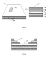
- Figure 1 shows a composite structure 11 known in the art formed by a plurality of layers 13, 15, 17, 19, 21, 23 with an optical fiber 25 embedded within it that can either be part of a network of sensors or it can be a data transmission element. If for any reason it were necessary to access said optical fiber 25 in order to repair it or for any type of maintenance operation, it is possible to reach it by means of composite repair techniques consisting of the local removal of parts of the reinforcement layers 13, 15, until reaching layers 17, 19 where said fiber is embedded.
- optical fiber 25 is a very fragile element and operations for removing parts of the layers 13, 15, 17 can damage it, as is shown in Figure 2 ; therefore by following the process known in the art, access to the optical fiber 25 without damaging it for the purpose of extracting it is very complex and costly.
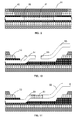
- the structure 11 includes a tubular protective cover 27 which allows reaching the optical fiber 25 without damaging it as is shown in Figure 3 et seq . in order to repair it.
- the possibilities of the continued existence of the optical fiber 25 increase greatly by using said cover 27 locally, protecting the optical fiber 25 formed by a core 31, a cladding 32 and a buffer coating 33.
- the protective cover 27 is sized such that between it and the optical fiber 25 there is an interface 29 that can be left open during the manufacturing process of the structure so that it can subsequently be filled with the matrix resin, or it can be closed with a filler material such as silicone to prevent resin from entering the tube.
- the protective cover 27 can be made of any material the toughness of which allows reaching it without damaging the optical fiber located inside it.
- the protective cover 27 can further have the secondary function of facilitating detection of the fiber 25 in the structure 11 by means of nondestructive inspection techniques (X-ray, ultrasound inspection or simply a metal detector).
- nondestructive inspection techniques X-ray, ultrasound inspection or simply a metal detector.
- Figures 3-9 sequentially illustrate the steps comprising the process of repairing the optical fiber 25 embedded in a composite structure 11 according to the present invention in a first embodiment thereof.
- the protective cover 27 After having identified the optical fiber 25 area in need of repair and having removed the parts of the layers 13, 15 and 17 necessary to do so, it will be extracted from the structure 11 and the cover 27 will be partially or completely removed (see Figures 5 and 6 ), allowing access to the fiber 25 for its repair or for performing the required maintenance operations by reconnecting again the ends 41, 43 previously separated by means of a splice 45 (see Figure 7 ). After this, the optical fiber 25 would be relocated in its position inside the structure 11 and the removed parts of the layers 13, 15, 17 (see Figure 8 ) will be returned.
- the repaired optical fiber 25 can optionally be provided with a new protective cover 27 (see Figure 9 ).
- the process would be similar except in that the repair of the optical fiber 25 would be performed by connecting one of the ends 51 of the embedded optical fiber 25 to one end 53 of an external optical fiber 55, therefore reconducting the optical signal through a path that is an alternative to the original one (see Figures 10-13 ).
Landscapes
- Physics & Mathematics (AREA)
- General Physics & Mathematics (AREA)
- Chemical & Material Sciences (AREA)
- Analytical Chemistry (AREA)
- Engineering & Computer Science (AREA)
- Mechanical Engineering (AREA)
- Light Guides In General And Applications Therefor (AREA)
- Mechanical Coupling Of Light Guides (AREA)
- Communication Cables (AREA)
Abstract
Description
- The present invention relates to a composite structure incorporating embedded optical fiber for structural monitoring purposes, and more particularly to a composite structure of an aircraft, as well as a process for its repair.
- The intensive introduction of advanced composites in primary structures has become a fundamental process of structural optimization (based on weight savings and the improvement of mechanical properties), one of the top priorities in the design and manufacture of a new generation of aircrafts. The introduction of an effective structural monitoring system capable of predicting the failure of load paths in a structure designed according to damage tolerance criteria would allow optimizing its design and, accordingly, reducing its weight.
- Optical fiber sensors can be effectively used to measure thermomechanical deformation and even to detect damage events operating both alone in passive structural monitoring systems and in combination with other devices, forming active monitoring systems. One of their main advantages is their capacity to be embedded in composite structures, being intimately integrated into the structures.
- However, one of the drawbacks of this integration is the difficulty that the repair of these optical fiber lines has once they are embedded. Optical fiber has extremely small dimensions and is fragile in handling with the tools normally used in repairing composites, therefore the possibilities of accessing it once it is embedded are very slim. This is incompatible with the reparability requirements needed when the structural health and maintenance criteria are bound to the correct working of the network of sensors integrated in the structure.
- The present invention is aimed at solving this drawback.
- In a first aspect, the present invention proposes a composite structure formed by a plurality of layers including an optical fiber for structural monitoring purposes which is at least partly embedded in said structure, in which the optical fiber has a tubular protective cover in those areas of the embedded part susceptible to requiring repair.
- The incorporation of this protective cover facilitates access to the optical fiber for its repair or maintenance, preventing its deterioration.
- In a second aspect the present invention proposes a process of repairing the optical fiber embedded in said composite structure comprising the following steps:
- Identifying the optical fiber area in need of repair.
- Removing part of the layers of material until reaching the optical fiber area in need of repair.
- Extracting the optical fiber area in need of repair from the composite structure.
- Removing the protective cover.
- Repairing the optical fiber.
- Optionally providing a new protective cover for the repaired optical fiber area.
- Relocating the repaired optical fiber area in the composite structure.
- Returning the removed parts of the layers of material.
- Other features and advantages of the present invention will be understood from the following detailed description of an illustrative embodiment of its object in relation to the attached figures.
-
-
Figure 1 shows a schematic perspective view of a composite structure known in the art formed by six layers with an optical fiber embedded between the two central layers longitudinally to the reinforcement fibers and a cross-sectional view of area A of said structure. -
Figure 2 shows a cross-sectional view of the structure ofFigure 1 in which, using conventional composite structure repair techniques, parts of three layers have been removed by means of sanding until reaching the embedded optical fiber that has been damaged during the process. -
Figure 3 shows a sectional view of a composite structure according to a first embodiment of the present invention in which the optical fiber embedded between the two central layers of the six layers forming the structure have a local protective cover. -
Figure 4 shows with greater detail front sectional and cross-sectional views of part B ofFigure 3 . -
Figure 5 shows the same view asFigure 3 after cutting the protective cover in order to reach the optical fiber and be able to repair it. -
Figure 6 shows the same view asFigure 5 after removing the protective cover in order to reconnect the optical fiber line by joining its ends after the suitable maintenance operations. -
Figure 7 shows the same view asFigure 6 after having connected, by means of fusion splicing or any other standard process, the ends of the optical fiber. -
Figure 8 shows the same view asFigure 7 with the optical fiber repaired and the structure reconstituted. -
Figure 9 shows the same view asFigure 8 with the optical fiber inside a protective cover. -
Figure 10 shows a second embodiment of the invention in a view which is similar to that ofFigure 9 , in which the embedded optical fiber is repaired by means of an external optical fiber line. -
Figure 11 shows the same view asFigure 10 after having connected the end of the embedded optical fiber with the end of the external fiber line by means of fusion splicing or any other standard process. -
Figure 12 shows the same view asFigure 11 with the optical fiber repaired and the structure reconstituted. -
Figure 13 shows the same view asFigure 12 with the embedded optical fiber inside a protective cover. -
Figure 1 shows acomposite structure 11 known in the art formed by a plurality oflayers optical fiber 25 embedded within it that can either be part of a network of sensors or it can be a data transmission element. If for any reason it were necessary to access saidoptical fiber 25 in order to repair it or for any type of maintenance operation, it is possible to reach it by means of composite repair techniques consisting of the local removal of parts of thereinforcement layers layers optical fiber 25 is a very fragile element and operations for removing parts of thelayers Figure 2 ; therefore by following the process known in the art, access to theoptical fiber 25 without damaging it for the purpose of extracting it is very complex and costly. - According to the invention, the
structure 11 includes a tubularprotective cover 27 which allows reaching theoptical fiber 25 without damaging it as is shown inFigure 3 et seq. in order to repair it. - The possibilities of the continued existence of the
optical fiber 25 increase greatly by using saidcover 27 locally, protecting theoptical fiber 25 formed by acore 31, a cladding 32 and abuffer coating 33. - The
protective cover 27 is sized such that between it and theoptical fiber 25 there is aninterface 29 that can be left open during the manufacturing process of the structure so that it can subsequently be filled with the matrix resin, or it can be closed with a filler material such as silicone to prevent resin from entering the tube. - The
protective cover 27 can be made of any material the toughness of which allows reaching it without damaging the optical fiber located inside it. - The
protective cover 27 can further have the secondary function of facilitating detection of thefiber 25 in thestructure 11 by means of nondestructive inspection techniques (X-ray, ultrasound inspection or simply a metal detector). -
Figures 3-9 sequentially illustrate the steps comprising the process of repairing theoptical fiber 25 embedded in acomposite structure 11 according to the present invention in a first embodiment thereof. - Once the
protective cover 27 has been accessed, after having identified theoptical fiber 25 area in need of repair and having removed the parts of thelayers structure 11 and thecover 27 will be partially or completely removed (seeFigures 5 and6 ), allowing access to thefiber 25 for its repair or for performing the required maintenance operations by reconnecting again theends Figure 7 ). After this, theoptical fiber 25 would be relocated in its position inside thestructure 11 and the removed parts of thelayers Figure 8 ) will be returned. The repairedoptical fiber 25 can optionally be provided with a new protective cover 27 (seeFigure 9 ). - In a second embodiment of the invention, the process would be similar except in that the repair of the
optical fiber 25 would be performed by connecting one of theends 51 of the embeddedoptical fiber 25 to oneend 53 of an externaloptical fiber 55, therefore reconducting the optical signal through a path that is an alternative to the original one (seeFigures 10-13 ). - In the preferred embodiment described above any modifications comprised within the scope defined by the following claims can be introduced.
Claims (8)
- A composite structure (11) formed by a plurality of layers (13, 15, 17, 19, 21, 23) including an optical fiber (25) for structural monitoring purposes which is at least partly embedded in said structure (11), characterized in that said optical fiber (25) incorporates a protective cover (27) in those areas of its embedded part susceptible to needing repair.
- A composite structure (11) according to claim 1, characterized in that said cover (27) is made of a material the tenacity of which allows reaching the optical fiber (25) located inside it without damaging it.
- A composite structure (11) according to claim 2, characterized in that the space (29) comprised between the protective cover (27) and the optical fiber (25) is occupied by a filler material.
- A composite structure (11) according to claim 2, characterized in that the space (29) comprised between the protective cover (27) and the optical fiber (25) is occupied by the matrix resin of the structure (11).
- A process of repairing the optical fiber (25) embedded in a composite structure (11) according to claims 1 to 4, characterized in that it comprises the following steps:a) Identifying the optical fiber (25) area in need of repair;b) Removing parts of the layers of material (13, 15, 17) until reaching the protective cover (27) of the optical fiber (25) area in need of repair;c) Extracting the optical fiber (25) area in need of repair from the composite structure (11);d) Removing the protective cover (27);e) Repairing the optical fiber (25);f) Relocating the repaired optical fiber (25) area in the composite structure (11);g) Returning the parts of the layers of material (13, 15, 17) removed in step b).
- A process of repairing the optical fiber (25) embedded in a composite structure (11) according to claim 5, characterized in that step e) includes the additional step of providing a new protective cover (27) for the repaired optical fiber (25) area.
- A process of repairing the optical fiber (25) embedded in a composite structure (11) according to claim 6, characterized in that the repaired optical fiber area connects ends (41, 43) of optical fiber (25) embedded in the composite structure.
- A process of repairing the optical fiber (25) embedded in a composite structure (11) according to claim 6, characterized in that the repaired optical fiber area connects one end (51) of optical fiber (25) embedded in the composite structure (11) with one end (53) of an optical fiber (55) located outside the composite structure (11).
Applications Claiming Priority (1)
| Application Number | Priority Date | Filing Date | Title |
|---|---|---|---|
| PCT/ES2005/070166 WO2007063145A1 (en) | 2005-11-30 | 2005-11-30 | Composite material structure with embedded optical fibre and method for repairing same |
Publications (2)
| Publication Number | Publication Date |
|---|---|
| EP1965237A1 true EP1965237A1 (en) | 2008-09-03 |
| EP1965237A4 EP1965237A4 (en) | 2012-07-18 |
Family
ID=38087637
Family Applications (1)
| Application Number | Title | Priority Date | Filing Date |
|---|---|---|---|
| EP05825247A Withdrawn EP1965237A4 (en) | 2005-11-30 | 2005-11-30 | Composite material structure with embedded optical fibre and method for repairing same |
Country Status (7)
| Country | Link |
|---|---|
| US (1) | US7706650B2 (en) |
| EP (1) | EP1965237A4 (en) |
| JP (1) | JP5208759B2 (en) |
| AU (1) | AU2005338588B2 (en) |
| CA (1) | CA2631613C (en) |
| IL (1) | IL191871A0 (en) |
| WO (1) | WO2007063145A1 (en) |
Families Citing this family (12)
| Publication number | Priority date | Publication date | Assignee | Title |
|---|---|---|---|---|
| JP5208759B2 (en) * | 2005-11-30 | 2013-06-12 | エアバス オペレーションズ、ソシエダ リミタダ | Composite structure embedded with optical fiber and repair method thereof |
| DE102007030025B3 (en) * | 2007-06-29 | 2008-10-16 | Airbus Deutschland Gmbh | - Process for repairing damaged region of aircraft fiber bonded component has integrated fiber optics useful in aircraft repair technology gives very strong repair especially effective in minimizing damage to aircraft by stone impact |
| EP2255235B1 (en) * | 2008-03-13 | 2016-11-16 | ADC Telecommunications, Inc. | Method of attachment of a connector to a fiber optic cable |
| ES2368541B1 (en) * | 2008-10-16 | 2012-09-25 | Rodriser Industria Aeronáutica Española, S.L. | PATCH IMPLEMENTATION PROCEDURE FOR REPAIR OF AIRCRAFT STRUCTURES AND PATCH USED IN THIS PROCEDURE. |
| DE102008062700A1 (en) | 2008-12-17 | 2010-07-01 | Airbus Deutschland Gmbh | Pre-installed, customizable airline network |
| DE102010039153B4 (en) | 2010-08-10 | 2012-04-19 | Airbus Operations Gmbh | Method for connecting a fiber-optic cable embedded in a fiber composite component with an external optical fiber |
| US8870473B2 (en) | 2010-09-14 | 2014-10-28 | Adc Telecommunications, Inc. | Method of terminating a fiber optic cable |
| JP5725455B2 (en) * | 2011-06-08 | 2015-05-27 | 国立大学法人 東京大学 | Embedded optical fiber repair method and repair structure of composite structure |
| US20130050685A1 (en) * | 2011-08-23 | 2013-02-28 | The Boeing Company | Composite structure having an embedded sensing system |
| US9170172B2 (en) | 2011-08-23 | 2015-10-27 | The Boeing Company | Composite structure having an embedded sensing system |
| CN102555227A (en) * | 2011-11-15 | 2012-07-11 | 中国航空工业集团公司北京航空材料研究院 | Method for monitoring impact threats of composite material part structure in non-interference mode |
| US9500561B2 (en) * | 2014-06-20 | 2016-11-22 | Bell Helicopter Textron Inc. | Embedding fiber optic cables in rotorcraft composites |
Family Cites Families (38)
| Publication number | Priority date | Publication date | Assignee | Title |
|---|---|---|---|---|
| US3466219A (en) | 1965-08-09 | 1969-09-09 | Us Air Force | Fiber reinforced plastic composite material |
| US3716869A (en) | 1970-12-02 | 1973-02-13 | Nasa | Millimeter wave antenna system |
| US3755713A (en) | 1972-07-25 | 1973-08-28 | Boeing Co | Electrically conductive surface for aircraft |
| US4318964B1 (en) * | 1977-03-01 | 1999-12-07 | Autosplice Inc | Autopin machine |
| US4221041A (en) | 1978-10-02 | 1980-09-09 | Boeing Commercial Airplane Company | Semi-tubular rivets and method of using |
| US4318954A (en) | 1981-02-09 | 1982-03-09 | Boeing Aerospace Company | Printed wiring board substrates for ceramic chip carriers |
| IT1218709B (en) | 1981-06-30 | 1990-04-19 | Boeing Co | METHOD OF MANUFACTURE OF A PREFORMED USING A COMPOSITE MATERIAL REINFORCED WITH FIBERS |
| US4580874A (en) * | 1983-06-27 | 1986-04-08 | Olin Corporation | Optical fiber cable repair and joining technique and kit for performing the same |
| US4585304A (en) * | 1983-09-06 | 1986-04-29 | Virginia | Technique for repairing and joining small diameter optical fiber cables |
| JPS60176006A (en) * | 1984-02-22 | 1985-09-10 | Kanai Hiroyuki | Joining method of optical fibers |
| US5346367A (en) | 1984-12-21 | 1994-09-13 | United Technologies Corporation | Advanced composite rotor blade |
| US4836030A (en) * | 1985-05-20 | 1989-06-06 | Lockheed Corporation | Method of testing composite materials for structural damage |
| US4888076A (en) * | 1988-07-05 | 1989-12-19 | Lockheed Corporation | Method of coupling optical fibers enbedded in a molded article to the exterior thereof |
| US4936649A (en) * | 1989-01-25 | 1990-06-26 | Lymer John D | Damage evaluation system and method using optical fibers |
| JP2700827B2 (en) * | 1989-09-14 | 1998-01-21 | 株式会社フジクラ | Road surface temperature distribution measurement device |
| US6086975A (en) | 1991-01-16 | 2000-07-11 | The Boeing Company | Lighting protection for electrically conductive or insulating skin and core for honeycomb structure |
| FR2677137A1 (en) * | 1991-05-29 | 1992-12-04 | Alcatel Cable | Method of repairing a fibre-optic microtube |
| FR2685081B1 (en) | 1991-12-11 | 1994-02-04 | Thomson Csf | STRUCTURE WITH INTRINSICALLY DAMAGED CONTROL, MANUFACTURING METHOD AND METHOD OF USE. |
| JP3006417B2 (en) * | 1994-07-15 | 2000-02-07 | 日本鋼管株式会社 | Detection method of refractory wear of tapping gutter |
| AR004288A1 (en) * | 1995-11-13 | 1998-11-04 | Siemens Ag | OPTICAL FIBER CABLE INSTALLATION STRUCTURE. |
| US6035084A (en) * | 1997-11-13 | 2000-03-07 | Mcdonell Douglas Corporation | Fiber optic connector and associated method for establishing an optical connection with an optical fiber embedded within a composite structure |
| US7351009B2 (en) * | 1998-05-06 | 2008-04-01 | Corning Cable Systems Llc | Fiber optic installation structures in a paved surface, ducts, and methods therefor |
| US6195486B1 (en) * | 1998-06-02 | 2001-02-27 | Siecor Operations, Llc | Fiber optic cable having a component with an absorptive polymer coating and a method of making the cable |
| US6377738B1 (en) * | 1998-12-04 | 2002-04-23 | Pirelli Cable Corporation | Optical fiber cable and core with a reinforced buffer tube having visible strength members and methods of manufacture thereof |
| JP3243461B2 (en) | 1999-07-30 | 2002-01-07 | 川崎重工業株式会社 | Sandwich structure |
| DE19956394B4 (en) | 1999-11-24 | 2005-02-03 | Airbus Deutschland Gmbh | Process for producing a profile from a hybrid material |
| GB0000405D0 (en) * | 2000-01-11 | 2000-03-01 | British Aerospace | Improvements relating to interfacing embedded optical transmission structures |
| GB0000415D0 (en) * | 2000-01-11 | 2000-03-01 | British Aerospace | Improvements relating to interfacing embedded optical transmission structures |
| US20020154873A1 (en) * | 2001-01-26 | 2002-10-24 | Fiber-Line, Inc. | Core enclosures and methods for making the same |
| DE10111640A1 (en) * | 2001-03-10 | 2002-10-02 | Airbus Gmbh | Procedure for the detection and reporting of overheating and fires in an aircraft |
| EP1342554B1 (en) | 2002-03-08 | 2010-02-03 | Airbus Deutschland GmbH | Method for making textile preforms from textile half-products |
| US7092605B2 (en) * | 2003-01-30 | 2006-08-15 | Commscope Properties, Llc | Fiber optic cable with composite polymeric/metallic armor |
| DE10326422A1 (en) | 2003-06-10 | 2005-01-05 | Eads Deutschland Gmbh | Fiber reinforced plastic profile with internal ribs manufacturing process involves wrapping cores in fiberous material, placing the cores together and wrapping again around the combined profile |
| JP4264301B2 (en) * | 2003-06-13 | 2009-05-13 | 新日本製鐵株式会社 | Diagnostic method for temperature sensor, refractory and refractory lining |
| US7781725B2 (en) * | 2004-10-21 | 2010-08-24 | Mossman Guy E | Optical fiber based sensor system suitable for monitoring remote aqueous infiltration |
| ES2345548T3 (en) * | 2004-12-28 | 2010-09-27 | Airbus Operations, S.L. | APPEARANCE MONITORING PROCEDURE AND STRUCTURAL DAMAGE PROGRESSION IN MONOLITIC STRUCTURES OF COMPOSITE MATERIAL USING BRAGG DIFFACTION NETWORKS. |
| ES2457023T3 (en) * | 2005-11-30 | 2014-04-24 | Airbus Operations S.L. | Structure of composite fiber optic material embedded in one of its surface layers and procedure for connection and repair |
| JP5208759B2 (en) * | 2005-11-30 | 2013-06-12 | エアバス オペレーションズ、ソシエダ リミタダ | Composite structure embedded with optical fiber and repair method thereof |
-
2005
- 2005-11-30 JP JP2008542780A patent/JP5208759B2/en not_active Expired - Fee Related
- 2005-11-30 EP EP05825247A patent/EP1965237A4/en not_active Withdrawn
- 2005-11-30 AU AU2005338588A patent/AU2005338588B2/en not_active Ceased
- 2005-11-30 CA CA2631613A patent/CA2631613C/en not_active Expired - Lifetime
- 2005-11-30 WO PCT/ES2005/070166 patent/WO2007063145A1/en not_active Ceased
-
2006
- 2006-05-25 US US11/441,272 patent/US7706650B2/en not_active Expired - Lifetime
-
2008
- 2008-06-01 IL IL191871A patent/IL191871A0/en not_active IP Right Cessation
Also Published As
| Publication number | Publication date |
|---|---|
| EP1965237A4 (en) | 2012-07-18 |
| IL191871A0 (en) | 2008-12-29 |
| WO2007063145A1 (en) | 2007-06-07 |
| US20070122098A1 (en) | 2007-05-31 |
| AU2005338588B2 (en) | 2013-01-24 |
| CA2631613C (en) | 2012-11-27 |
| JP2009517705A (en) | 2009-04-30 |
| AU2005338588A1 (en) | 2007-06-07 |
| CA2631613A1 (en) | 2007-06-07 |
| JP5208759B2 (en) | 2013-06-12 |
| US7706650B2 (en) | 2010-04-27 |
Similar Documents
| Publication | Publication Date | Title |
|---|---|---|
| US7706650B2 (en) | Composite structure with embedded optical fiber and a process for its repair | |
| US8368749B2 (en) | Article inspection apparatus | |
| AU2005338589B2 (en) | Composite material structure having an embedded optical fibre in one of the surface layers thereof and method for connecting and repairing same | |
| US6547448B2 (en) | Embeddable fiber optic connector and associated method | |
| AR021442A1 (en) | AN OPTICAL FIBER NUCLEUS, AN OPTICAL FIBER CABLE THAT INCLUDES SUCH NUCLEUS AND MANUFACTURING METHODS OF A REINFORCED SEPARATOR TUBE. | |
| EP3124218A1 (en) | Monolithic primary structural part for aircraft and processes for manufacturing it | |
| CN103217109A (en) | Crack monitoring sensor and use method thereof based on OTDR (optical time domain reflectometry) technique | |
| CN104512439A (en) | Route unlocking method and device | |
| US6952505B2 (en) | Interfacing optical transmission structures | |
| ITTO20080908A1 (en) | PROCEDURE FOR THE PROGNOSTICS OF A STRUCTURE UNDER LOADED LOADS. | |
| Wang et al. | Mechanical response and critical failure mechanism characterization of notched carbon fiber reinforced polymer laminate subjected to tensile loading | |
| EP2603824B1 (en) | Method for connecting an optical waveguide, embedded in a fibre composite component, to an external optical waveguide | |
| JP5984603B2 (en) | Wiring risk judgment method and wiring risk judgment system | |
| Kashtalyan et al. | Coupled stress and energy criterion for multiple matrix cracking in cross-ply composite laminates | |
| JP2012255856A (en) | Repair method of embedded optical fiber of composite material structure, repair structure, and connection structure | |
| Du et al. | Qualification Methodology for Advanced Rotary Shouldered Threaded Connections | |
| JP3242154U (en) | Optical cable connecting device | |
| Elliott et al. | Model calibration efforts for the international space station's solar array mast | |
| EP3586179B1 (en) | Blown optical fibre unit and related method of manufacturing | |
| RU2407670C2 (en) | Method of setting sizes of and developing reinforced structural components, using structural state pickups, and aircraft | |
| CN116846468A (en) | A remote monitoring and management method, device and system for transmission network | |
| DE102012108830A1 (en) | Fiber optic cable | |
| JP2006209023A (en) | Fiber optic cable | |
| WO2026024532A1 (en) | Tight buffer for hollow core fibers | |
| Freger et al. | The Effect of Structural and Geometrical Parameters on Rod Properties |
Legal Events
| Date | Code | Title | Description |
|---|---|---|---|
| PUAI | Public reference made under article 153(3) epc to a published international application that has entered the european phase |
Free format text: ORIGINAL CODE: 0009012 |
|
| 17P | Request for examination filed |
Effective date: 20080619 |
|
| AK | Designated contracting states |
Kind code of ref document: A1 Designated state(s): AT BE BG CH CY CZ DE DK EE ES FI FR GB GR HU IE IS IT LI LT LU LV MC NL PL PT RO SE SI SK TR |
|
| RIN1 | Information on inventor provided before grant (corrected) |
Inventor name: MENENDEZ MARTIN, JOSE MANUEL |
|
| RAP1 | Party data changed (applicant data changed or rights of an application transferred) |
Owner name: AIRBUS OPERATIONS S.L. |
|
| A4 | Supplementary search report drawn up and despatched |
Effective date: 20120614 |
|
| RIC1 | Information provided on ipc code assigned before grant |
Ipc: B32B 27/00 20060101ALI20120608BHEP Ipc: G01N 21/00 20060101ALI20120608BHEP Ipc: G02B 6/44 20060101AFI20120608BHEP Ipc: G02B 6/24 20060101ALI20120608BHEP |
|
| DAX | Request for extension of the european patent (deleted) | ||
| 17Q | First examination report despatched |
Effective date: 20130429 |
|
| STAA | Information on the status of an ep patent application or granted ep patent |
Free format text: STATUS: THE APPLICATION IS DEEMED TO BE WITHDRAWN |
|
| 18D | Application deemed to be withdrawn |
Effective date: 20130910 |