EP1965109A1 - Soupape thermostatique et robinet de mixeur avec TMV intégré - Google Patents
Soupape thermostatique et robinet de mixeur avec TMV intégré Download PDFInfo
- Publication number
- EP1965109A1 EP1965109A1 EP20080153877 EP08153877A EP1965109A1 EP 1965109 A1 EP1965109 A1 EP 1965109A1 EP 20080153877 EP20080153877 EP 20080153877 EP 08153877 A EP08153877 A EP 08153877A EP 1965109 A1 EP1965109 A1 EP 1965109A1
- Authority
- EP
- European Patent Office
- Prior art keywords
- water
- housing
- tap
- mixing device
- thermostatic
- Prior art date
- Legal status (The legal status is an assumption and is not a legal conclusion. Google has not performed a legal analysis and makes no representation as to the accuracy of the status listed.)
- Granted
Links
- XLYOFNOQVPJJNP-UHFFFAOYSA-N water Substances O XLYOFNOQVPJJNP-UHFFFAOYSA-N 0.000 claims abstract description 123
- 238000009434 installation Methods 0.000 claims abstract description 16
- 230000000903 blocking effect Effects 0.000 claims description 6
- 230000006378 damage Effects 0.000 claims description 5
- 239000012530 fluid Substances 0.000 abstract description 2
- 239000000203 mixture Substances 0.000 description 8
- 239000003651 drinking water Substances 0.000 description 5
- 238000012423 maintenance Methods 0.000 description 5
- 229910001369 Brass Inorganic materials 0.000 description 3
- 230000008901 benefit Effects 0.000 description 3
- 239000010951 brass Substances 0.000 description 3
- 235000020188 drinking water Nutrition 0.000 description 3
- 230000001105 regulatory effect Effects 0.000 description 3
- 235000012206 bottled water Nutrition 0.000 description 2
- 230000001680 brushing effect Effects 0.000 description 2
- 238000010276 construction Methods 0.000 description 2
- 230000009977 dual effect Effects 0.000 description 2
- 230000007246 mechanism Effects 0.000 description 2
- 238000009428 plumbing Methods 0.000 description 2
- 238000005303 weighing Methods 0.000 description 2
- 208000027418 Wounds and injury Diseases 0.000 description 1
- 230000009471 action Effects 0.000 description 1
- 230000004888 barrier function Effects 0.000 description 1
- 230000015572 biosynthetic process Effects 0.000 description 1
- 238000005266 casting Methods 0.000 description 1
- 239000000919 ceramic Substances 0.000 description 1
- 238000011109 contamination Methods 0.000 description 1
- 230000006866 deterioration Effects 0.000 description 1
- 238000004512 die casting Methods 0.000 description 1
- 230000035622 drinking Effects 0.000 description 1
- 238000011010 flushing procedure Methods 0.000 description 1
- 238000005242 forging Methods 0.000 description 1
- 238000005755 formation reaction Methods 0.000 description 1
- 208000014674 injury Diseases 0.000 description 1
- 238000012986 modification Methods 0.000 description 1
- 230000004048 modification Effects 0.000 description 1
- 239000002245 particle Substances 0.000 description 1
- 230000037361 pathway Effects 0.000 description 1
- 230000002250 progressing effect Effects 0.000 description 1
- 230000008844 regulatory mechanism Effects 0.000 description 1
- 239000007787 solid Substances 0.000 description 1
- 239000008400 supply water Substances 0.000 description 1
- 239000008399 tap water Substances 0.000 description 1
- 235000020679 tap water Nutrition 0.000 description 1
- 238000005406 washing Methods 0.000 description 1
Images

Classifications
-
- G—PHYSICS
- G05—CONTROLLING; REGULATING
- G05D—SYSTEMS FOR CONTROLLING OR REGULATING NON-ELECTRIC VARIABLES
- G05D23/00—Control of temperature
- G05D23/01—Control of temperature without auxiliary power
- G05D23/13—Control of temperature without auxiliary power by varying the mixing ratio of two fluids having different temperatures
- G05D23/1306—Control of temperature without auxiliary power by varying the mixing ratio of two fluids having different temperatures for liquids
- G05D23/132—Control of temperature without auxiliary power by varying the mixing ratio of two fluids having different temperatures for liquids with temperature sensing element
- G05D23/134—Control of temperature without auxiliary power by varying the mixing ratio of two fluids having different temperatures for liquids with temperature sensing element measuring the temperature of mixed fluid
- G05D23/1346—Control of temperature without auxiliary power by varying the mixing ratio of two fluids having different temperatures for liquids with temperature sensing element measuring the temperature of mixed fluid with manual temperature setting means
- G05D23/1353—Control of temperature without auxiliary power by varying the mixing ratio of two fluids having different temperatures for liquids with temperature sensing element measuring the temperature of mixed fluid with manual temperature setting means combined with flow controlling means
-
- F—MECHANICAL ENGINEERING; LIGHTING; HEATING; WEAPONS; BLASTING
- F16—ENGINEERING ELEMENTS AND UNITS; GENERAL MEASURES FOR PRODUCING AND MAINTAINING EFFECTIVE FUNCTIONING OF MACHINES OR INSTALLATIONS; THERMAL INSULATION IN GENERAL
- F16K—VALVES; TAPS; COCKS; ACTUATING-FLOATS; DEVICES FOR VENTING OR AERATING
- F16K11/00—Multiple-way valves, e.g. mixing valves; Pipe fittings incorporating such valves
- F16K11/02—Multiple-way valves, e.g. mixing valves; Pipe fittings incorporating such valves with all movable sealing faces moving as one unit
- F16K11/06—Multiple-way valves, e.g. mixing valves; Pipe fittings incorporating such valves with all movable sealing faces moving as one unit comprising only sliding valves, i.e. sliding closure elements
- F16K11/072—Multiple-way valves, e.g. mixing valves; Pipe fittings incorporating such valves with all movable sealing faces moving as one unit comprising only sliding valves, i.e. sliding closure elements with pivoted closure members
- F16K11/074—Multiple-way valves, e.g. mixing valves; Pipe fittings incorporating such valves with all movable sealing faces moving as one unit comprising only sliding valves, i.e. sliding closure elements with pivoted closure members with flat sealing faces
-
- F—MECHANICAL ENGINEERING; LIGHTING; HEATING; WEAPONS; BLASTING
- F16—ENGINEERING ELEMENTS AND UNITS; GENERAL MEASURES FOR PRODUCING AND MAINTAINING EFFECTIVE FUNCTIONING OF MACHINES OR INSTALLATIONS; THERMAL INSULATION IN GENERAL
- F16K—VALVES; TAPS; COCKS; ACTUATING-FLOATS; DEVICES FOR VENTING OR AERATING
- F16K27/00—Construction of housing; Use of materials therefor
- F16K27/02—Construction of housing; Use of materials therefor of lift valves
- F16K27/0263—Construction of housing; Use of materials therefor of lift valves multiple way valves
-
- F—MECHANICAL ENGINEERING; LIGHTING; HEATING; WEAPONS; BLASTING
- F16—ENGINEERING ELEMENTS AND UNITS; GENERAL MEASURES FOR PRODUCING AND MAINTAINING EFFECTIVE FUNCTIONING OF MACHINES OR INSTALLATIONS; THERMAL INSULATION IN GENERAL
- F16K—VALVES; TAPS; COCKS; ACTUATING-FLOATS; DEVICES FOR VENTING OR AERATING
- F16K27/00—Construction of housing; Use of materials therefor
- F16K27/04—Construction of housing; Use of materials therefor of sliding valves
- F16K27/044—Construction of housing; Use of materials therefor of sliding valves slide valves with flat obturating members
- F16K27/045—Construction of housing; Use of materials therefor of sliding valves slide valves with flat obturating members with pivotal obturating members
-
- Y—GENERAL TAGGING OF NEW TECHNOLOGICAL DEVELOPMENTS; GENERAL TAGGING OF CROSS-SECTIONAL TECHNOLOGIES SPANNING OVER SEVERAL SECTIONS OF THE IPC; TECHNICAL SUBJECTS COVERED BY FORMER USPC CROSS-REFERENCE ART COLLECTIONS [XRACs] AND DIGESTS
- Y10—TECHNICAL SUBJECTS COVERED BY FORMER USPC
- Y10T—TECHNICAL SUBJECTS COVERED BY FORMER US CLASSIFICATION
- Y10T137/00—Fluid handling
- Y10T137/0318—Processes
- Y10T137/0402—Cleaning, repairing, or assembling
- Y10T137/0491—Valve or valve element assembling, disassembling, or replacing
-
- Y—GENERAL TAGGING OF NEW TECHNOLOGICAL DEVELOPMENTS; GENERAL TAGGING OF CROSS-SECTIONAL TECHNOLOGIES SPANNING OVER SEVERAL SECTIONS OF THE IPC; TECHNICAL SUBJECTS COVERED BY FORMER USPC CROSS-REFERENCE ART COLLECTIONS [XRACs] AND DIGESTS
- Y10—TECHNICAL SUBJECTS COVERED BY FORMER USPC
- Y10T—TECHNICAL SUBJECTS COVERED BY FORMER US CLASSIFICATION
- Y10T137/00—Fluid handling
- Y10T137/598—With repair, tapping, assembly, or disassembly means
- Y10T137/6011—Assembling, disassembling, or removing cartridge type valve [e.g., insertable and removable as a unit, etc.]
- Y10T137/6014—Faucet type [e.g., domestic water use, etc.]
-
- Y—GENERAL TAGGING OF NEW TECHNOLOGICAL DEVELOPMENTS; GENERAL TAGGING OF CROSS-SECTIONAL TECHNOLOGIES SPANNING OVER SEVERAL SECTIONS OF THE IPC; TECHNICAL SUBJECTS COVERED BY FORMER USPC CROSS-REFERENCE ART COLLECTIONS [XRACs] AND DIGESTS
- Y10—TECHNICAL SUBJECTS COVERED BY FORMER USPC
- Y10T—TECHNICAL SUBJECTS COVERED BY FORMER US CLASSIFICATION
- Y10T137/00—Fluid handling
- Y10T137/794—With means for separating solid material from the fluid
- Y10T137/7976—Plural separating elements
Definitions
- the invention in a first aspect relates to mixer taps (US: faucets) having separate controls for hot and cold water.
- the invention in a second aspect relates to thermostatic mixing valve, usable to provide thermostatic regulation of temperature integrated within the tap body or in a separate unit.
- the two aspects can be combined or used separately.
- a mixer tap generally comprises hot and cold inlets and a common outlet (spout, nozzle, shower head) for delivering a desired mixture of cold and hot water.
- Different forms of control are available to regulate the flow and the mix.
- Separate hot and cold regulating controls are simplest to provide, but can be difficult to adjust before the correct temperature and flow rate is reached.
- Each control may be a rotary knob or a lever, for example, and may move through a quarter turn or several turns, according to the type of head works.
- Single-lever mixer tap controls are another option.
- movement about a first axis regulates the flow and movement about a second axis controls the mix.
- Another form of control having a single lever is the so-called sequential control in which movement of a single lever about a single axis first enables the flow and then progressively alters the mix (usually starting from cold and progressing toward hot).
- Yet another form of control popular with thermostatic mixing taps is one in which a first control regulates the flow and a second control regulates the temperature via a thermostatic mixing valve.
- the simple dual control permits the user to be sure that a "cold" output contains water purely from the cold supply. Such an assurance is generally required before water can be used for drinking (“potable water”), or even brushing teeth, for example.
- a small proportion of water from the hot supply is not included in the output. This might arise either from failure to set the control lever fully to the cold position, from poor design or from wear and tear of the valve components or from a deterioration in the performance of the thermostat element, due to wear and tear, in a thermostatic tap. In either case, a separate tap for drinking water must be provided, and inconvenience for the user, together with increased installation costs.
- the "hot” water output is typically a mix of hot water from the domestic hot water services (DHWS) at a temperature which is typically above 50° Celsius and cold water at ambient temperature, provided by a thermostatic mixer to ensure that water above, say, 40 or 42 degrees Celsius cannot be emitted even at the hottest setting.
- a variable temperature thermostat is part of the mixing tap, as in a shower installation, then the thermostatic valve is naturally included in the tap body.
- a simple hot/cold mixer tap is required, for example over a basin for washing hands or dishes
- the usual solution is to provide a thermostatic mixing valve separately from the tap fitting, for example beneath the sink or behind a wall panel.
- the same thermostat might provide a supply of such "mixed hot” water for more than one basin, using the DHWS hot and cold water service (CWS) supplies of the building, but only for a few and only in one location.
- CWS DHWS hot and cold water service
- the body of the integrated tap may need to be dismantled in several steps and even removed entirely from the wall in some cases, before access is obtained to the thermostat or other parts. Given the bulk of brass (typically) involved in accommodating the mechanism, these bodies may weigh 6kg or more, and are not trivial to handle safely. Even where the TMV is mounted separately from the tap, servicing can be difficult.
- the invention in its various aspects aims to enable the provision of safe hot water while avoiding or reducing one or more of the problems identified above.
- the invention in a first aspect provides a mixer tap comprising in a single housing:
- this step the benefits of an integrated tap are combined with the facility to obtain a pure cold water supply.
- this output may or may not strictly be potable, but at least it is known not to include water from the hot supply.
- the control means may comprise separate first and second controls nominally for regulating the hot and cold water independently, the first control in fact regulating flow of mixed water from the thermostatic mixing device to the common outlet, while the second control is said dedicated cold water control.
- first and second controls nominally for regulating the hot and cold water independently, the first control in fact regulating flow of mixed water from the thermostatic mixing device to the common outlet, while the second control is said dedicated cold water control.
- the thermostatic mixing device may include means for adjusting its output temperature.
- the adjusting means may be arranged to be manually operable by the user, or hidden for operation by service personnel only.
- the thermostatic mixing device may comprise a cartridge located in a chamber accessible by removing part of the single housing, in accordance with the second aspect of the invention defined below.
- the single housing may also provide chambers accommodating first and second strainer cartridges for blocking the passage of debris from the first or second inlet to the mixing device.
- the second strainer cartridge may serve also to block the passage of debris from the second inlet to the dedicated cold water control as well as to the mixing device.
- the housing may further accommodate first and second check valves for blocking the passage of water out through said inlets.
- the first and second check valves may be integrated in the first and second strainer cartridges respectively with the check valves preferably downstream from the strainers so that the strainers protect the check valves from damage due to debris.
- the first and second strainer cartridges and thermostatic mixing device may all be accessible for servicing by removal of a single cover part of the housing.
- the housing may comprise a monolithic inner body housing said thermostatic mixing device and being located within an outer casing, wherein a sealed space within the outer casing serves as a duct to pass water from a port formed in the inner body to said outlet.
- Said inner body may comprise first and second ports for emitting mixed and cold water respectively into the outer casing, the control means engaging with said ports to regulate the flow from each to the outlet.
- strainer cartridges these may also be located within the monolithic inner body.
- the tap may further comprise integrated isolating valves for isolating serviceable components including the mixing device from said inlets.
- Said isolating valves may be located within a spigot adapted for interfacing the single body to a supporting panel (wall, sink surround, worktop or the like), access for operating the isolating valves being provided without requiring access behind said panel.
- the invention in the second aspect provides a thermostatic mixing device comprising in a single housing:
- the device in one embodiment is a thermostatic mixer tap with integrated thermostatic mixing valve, the outlet being adapted for emitting said mixed water to a user, the device further comprising within said single housing:
- a “major part” in this context might be defined as any part or combination of parts comprising more than 30% of the weight of the complete device contained within and including said single housing.
- the thermostatic mixing device may be in the form of a cartridge removable from the housing for servicing or replacement.
- the thermostatic mixing device may be accessible through an opening in said single housing.
- the tap may further comprise a cover for hiding said opening in normal use, the cover preferably being independent of any functional component of the tap and preferably comprising less than 10%, preferably less than 7.5% and even less than 5% by weight of the complete tap as contained within and including said single housing. Even if a cover must be removed, this will be a far simpler and safer operation than in known integrated thermostatic mixer taps.
- to access the thermostatic cartridge first the temperature adjusting knob is removed, then the flow control lever (both brass die-castings), then the shower hose and connector are removed; then a light plastic cover is removed. Following this a large gear assembly and large ceramic disc are removed with five 5 no. M6 bolts, giving access to the thermostatic cartridge.
- the cover part may be located on an underside of the tap when installed.
- the thermostatic mixing device may include means for adjusting its output temperature.
- the adjusting means may be arranged to be manually operable by the user, or hidden for operation by service personnel only.
- the single housing may also accommodate first and second strainers for blocking the passage of debris from the first or second inlet to the mixing device, said strainers also being made accessible for servicing after installation of the tap without dismantling said control and without demounting said single housing.
- the housing may further accommodate first and second check valves for blocking the passage of water out through said inlets, said check valves also being made accessible for servicing after installation of the tap without dismantling said control and without demounting said single housing.
- the first and second check valves may be integrated in cartridges with the first and second strainers respectively with the check valves preferably downstream from the strainers so that the strainers protect the check valves from damage due to debris.
- the first and second strainers/cartridges and thermostatic mixing device may all be accessible for servicing by removal of a single cover of the housing.
- the cover part may comprise less than 10%, preferably less than 5% by weight of the complete tap as contained within and including said single housing.
- the main casting of the tap weighing over 5kg must be removed from the permanently mounted piece weighing only 1kg, in order to service the strainers and check valves (although check valves rarely require attention).
- the housing may comprise a monolithic inner body housing said thermostatic mixing device and being located within an outer casing, wherein a sealed space within the outer casing serves as a duct to pass water from a port formed in the inner body to said outlet.
- strainer cartridges these may also be located within the monolithic inner body.
- the tap may further comprise integrated isolating valves for isolating serviceable components including the mixing device from said inlets.
- Said isolating valves may be located within a spigot adapted for interfacing the single body to a supporting panel (wall, worktop or the like), access for operating the isolating valves being provided without requiring access behind said panel.
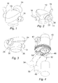
- Fig. 1 is a front perspective view of a thermostatic bib tap having an upper casing portion 10 housing a spout and a lower casing portion 12 housing operating parts to be described below. Portions 10 and 12 in this example are formed in a single piece although that is not essential. A spigot 14 is provided for attaching the tap to a wall. An on/off control 16 for hot water is located on the left-hand side of the body (as viewed by the user) and an on/off control 18 for cold water is provided on the right hand side of the body. Each control is of the quarter turn type, with a short lever moving from an upright (off) position as shown at the left to a forward (on) position as shown at the right. Off/on positions may equally be reversed, depending on the type of lever and ergonomic considerations. Spindle controls may equally be used, requiring more than a complete revolution to move from fully on to fully off.
- a flange where it mounts to the wall.
- entrance ports for connection to the water supply, including a hot water supply port 20 and cold water supply port 22.
- the construction is modular so that different lengths of spigot can be provided according to the setting. Different forms of spigot can be provided, adapted for example for supporting the tap on a horizontal worktop panel instead of a wall panel, or for mounting directly onto exposed pipe-work.
- the underside view of Fig. 3 shows the outlet port (spout) 24 which emits a flow of water which may be a mixture between cold and hot, according to the positions of the controls 16 and 18.
- the tap in this particular example includes a thermostatic device for mixing hot and cold supply water to a "safe hot” temperature, so that hot water from the entrance port 22 is never supplied directly from the DHWS to the outlet 24.
- the thermostat may deliver "hot" water at 40°C, for example, while the DHWS supply itself is at a more dangerous 60°, 70° or (for example in the event of a failure of the temperature control at the DHWS calorifier, hot water generator or hot water boiler) 80°C.
- the thermostatic device is housed with other components in the lower housing portion 12, and a screw cap 26 is provided which can be removed to permit access for servicing and/or replacement of these parts.
- ball valves are integrated into the spigot 14 and accessed through small ports 28 (hot) and 30 (cold), for example using a screwdriver.
- a thermostatic safety device is included within the body of the tap itself, with integrated isolating valves, but in such a way as to allow easy access for servicing.
- Fig. 4 shows an internal body 40 which may be a forging of solid brass, for example, and is housed within the lower body portion 12 of the tap. Although shown with the housing removed, internal body 40 is intended to be permanently secured and sealed within the body 10/12 before installation, and not removed for routine servicing.
- internal body 40 may be a forging of solid brass, for example, and is housed within the lower body portion 12 of the tap. Although shown with the housing removed, internal body 40 is intended to be permanently secured and sealed within the body 10/12 before installation, and not removed for routine servicing.
- the internal body 40 provides various ports, ducts and chambers. Visible in Fig. 4 , there is a hot water outlet 42 which co-operates with control 16 to allow hot (mixed hot) water into the upper part 10 of the housing, and hence to the spout 24. A similar port 44 (at the rear as seen in Fig. 4 ) provides the outlet for cold water in co-operation with control 18.
- body 40 there is a large opening for receiving a thermostatic mixing cartridge into a large mixing chamber 46 within the body 40.
- Further chambers 50 and 52 are provided to receive strainer and check valve cartridges 54 and 56 for the hot water and cold water supplies respectively. It will seen that these three items are readily accessible for servicing as soon as the cover 26 is removed from the tap housing, even though the housing and internal body part 40 remain undisturbed in relation to each other and the wall mounting. Needless to say, the isolating valves 28 and 30 in the spigot are to be closed before any of the cartridges is removed for servicing.
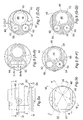
- Fig. 5(a) is a side view of the internal body 40.
- a threaded portion 58 provides for mounting of the cap 26, while seats 60 for O-rings facilitate a watertight seal within housing part 12.
- Fig. 5(b) is a plan view of the internal body 40, in which the axes of the mixing chamber 46, the hot water strainer and check valve cartridge chamber 50 and the cold water strainer and check valve cartridge chamber 52 are marked at 46', 50' and 52' respectively.
- the various plan sectional views are Figs. 6 to 9 and vertical sectional views are Figs. 10 to 12 will now be described, with different features of the internal structure of the main internal body 40 being visible in each section.
- FIG. 6 section A-A
- inner ports 62 and 64 receiving the supplies of hot and cold water from the external ports 20 and 22 respectively.
- An upper portion of the mixing chamber 46 can be seen.
- Fig. 7 shows the section on plane D-D, which is at the level of the outlet ports 42 (mixed hot water) and 44 (cold water).
- the thermostatic cartridge 48 can be seen in outline within mixing chamber 46.
- the internal form of the mixing cartridge is not relevant to an understanding to the present invention. It may for example be of the form described in our European patent EP0448315B1 .
- Strainer cartridge 56 can be seen within the cold strainer/check valve chamber 52. It will be seen immediately that the mixed hot outlet port 42 leads from the mixing chamber out to the hot water control 16, whereas the cold water outlet port 44 leads directly from the cold water inlet strainer chamber 52 to the outlet 44 and out through cold control 18.
- Fig. 8 on section F-F shows the transfer port 66 by which supply hot water enters a hot gallery space 68 surrounding the mixer cartridge 48 from chamber 50.
- Fig. 9 on section G-G shows a cold water transfer port 70 leading from the chamber 52 into a cold water gallery 72 surrounding the mixing cartridge 48.
- Fig. 10 is a section in the vertical plane C-C of Fig. 5(b) , showing further detail of the components and pathways related to the cold water.
- Cold water inlet 64 is seen at the top left, which leads into the cold water strainer/check valve chamber 52.
- Strainer/check valve cartridge 56 houses in its upper portion a straining mesh 74 and in its lower portion a check valve 76, which is to prevent contamination by the reverse flow of water from inside the valve towards inlet 64.
- the direct cold water outlet 44 can be seen, while the cold transfer port 70 allows passage of cold water from the check valve 76 into cold water gallery 72.
- mixing cartridge 48 O-rings and bridge formations within mixing chamber 46 isolate the galleries 68 and 72 from one another, and from the upper space into which the cartridge 48 dispenses mixed water at a controlled temperature.
- Cartridge 48 is mounted on a cap 80, which can be screwed out of the opening in body 40 to replace or service the thermostatic control.
- Hexagonal recesses 82 and 84 are provided for removing the mixing cartridge and cold strainer cartridge respectively using a standard hexagonal key.
- a temperature adjusting screw at the centre of the cap can be accessed to adjust the mixed water temperature without removing the cartridge. It will be understood that these can be accessed once the cap 26 ( Fig. 3 ) is removed from the housing.
- Fig. 11 is a similar cross-section but on line H-H, showing the parts relating primarily to the hot water.
- the hot water inlet 62 can be seen at the top left, leading into space 50 where the hot water strainer cartridge 54 includes straining mesh 86 and check valve 88. Hot water is led from the check valve outlet through hot water transfer port 66 into hot water gallery 68 surrounding the mixing cartridge 48.
- Fig. 12 shows in section M-M the outlet 42 for mixed water, which flows if permitted by control 16, into a final mixing space and duct within the outer housing 10 and hence to the spout 24.
- Distinctive features of the tap described relate to the ease of servicing of the tap components and also its basic functionality, comprising to the provision of a "pure" cold water outlet.
- thermostatic mixers for the provision of "safe" hot water use conventional hot and cold taps or mixer taps, with thermostatic valves located beneath the wash basin or behind a wall panel, where they can be difficult to access. Isolating valves and strainers are likewise difficult to access.
- integrated thermostatic mixer taps of the general type described herein do not necessarily integrate all the components (thermostatic cartridge, strainers, check valves and isolating valves), so that demounting of the tap and/or access behind or beneath panels is still required for many servicing operations. Moreover, access to the thermostatic elements, check valves etc.
- the user has no need then to be concerned with the difference between the mixing tap and drinking water supplies.
- lever action of either control may be reversed and/or replaced with a spindle or other type of flow regulation mechanism.
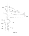
- Fig. 13 illustrates a thermostatic mixing device having easy servicing features similar to the mixer tap with integrated TMV described above, but in a slightly different application.
- water is to be supplied to a wash hand basin 100, mounted on a wall 102.
- the tap is of a no-touch (electronic) type, delivering water from a spout 104, under control of an infra-red or similar proximity sensor 106.
- These elements are part of an electronic valve assembly, whose functional parts are mounted in a body 108 behind the wall panel.
- a thermostatic mixing device 110 of the type seen in Figs. 4-12 is mounted behind the wall 102 in housing 112.
- Hot and cold supply pipes 114 and 116 enter the housing 112 and are coupled to inlets 62 and 64 of the device, while outlet pipe 116 leads safe hot water from the mixed water outlet of the device 110 to the electronic valve 108.
- Device 110 includes an internal body and serviceable cartridges substantially the same as body 40 and cartridges 48, 54, 56 of Figs. 4-12 . It is a simple matter for the person skilled in the art to provide a housing 112 which leads water from the mixed water outlet 42 of the internal body 40 to a pipe connection, rather than directly to the control valves and mixing space of the integrated mixer tap. Housing 112 projects through the wall 102, where cap 118 (similar to cap 26 in Figs. 1-3 ) is accessible and readily removable for servicing of the thermostatic mixing cartridge, check valves and strainers. Of course the housing 112 need not be mounted in a wall panel. Where it is, the housing and/or wall 102 can be adapted also to provide screwdriver access to isolating valves (not shown in Fig. 13 ) at the inlets, just as in the integrated version of Figs. 1-3 .
- housings 112 and 108 can be integrated if desired, providing the tap and servicing cover 118 in one place.
- the thermostatic mixing device can be used with a mixing tap to mix both cold and safe hot water in varying proportions, with the user controls and outlet in a separate housing from the thermostatic mixing device, rather than integrated as in Figs. 1-3 .
- both cold and mixed outlet pipes would be used to transfer water from device 110 to the tap body 108.
- Housing 112 could be adapted to lead the 'pure cold' water outlet 44 to a second outlet pipe connection.
- a 'pure cold' connection can be made simply enough by pipework direct to the tap body.
Landscapes
- Engineering & Computer Science (AREA)
- General Engineering & Computer Science (AREA)
- Mechanical Engineering (AREA)
- Physics & Mathematics (AREA)
- General Physics & Mathematics (AREA)
- Automation & Control Theory (AREA)
- Domestic Plumbing Installations (AREA)
- Multiple-Way Valves (AREA)
- Lubricants (AREA)
- Solid-Sorbent Or Filter-Aiding Compositions (AREA)
- Amplifiers (AREA)
- Stabilization Of Oscillater, Synchronisation, Frequency Synthesizers (AREA)
- Secondary Cells (AREA)
- Catching Or Destruction (AREA)
- Sampling And Sample Adjustment (AREA)
- Means For Warming Up And Starting Carburetors (AREA)
- Manufacturing And Processing Devices For Dough (AREA)
- Temperature-Responsive Valves (AREA)
Applications Claiming Priority (2)
| Application Number | Priority Date | Filing Date | Title |
|---|---|---|---|
| GB0526331A GB0526331D0 (en) | 2005-12-23 | 2005-12-23 | Mixer tap |
| EP06831472A EP1963723B1 (fr) | 2005-12-23 | 2006-12-22 | Valve thermostatique et robinet mitigeur a valve de melange thermostatique integree |
Related Parent Applications (2)
| Application Number | Title | Priority Date | Filing Date |
|---|---|---|---|
| EP06831472.3 Division | 2006-12-22 | ||
| EP06831472A Division EP1963723B1 (fr) | 2005-12-23 | 2006-12-22 | Valve thermostatique et robinet mitigeur a valve de melange thermostatique integree |
Publications (2)
| Publication Number | Publication Date |
|---|---|
| EP1965109A1 true EP1965109A1 (fr) | 2008-09-03 |
| EP1965109B1 EP1965109B1 (fr) | 2011-08-24 |
Family
ID=35841149
Family Applications (2)
| Application Number | Title | Priority Date | Filing Date |
|---|---|---|---|
| EP20080153877 Active EP1965109B1 (fr) | 2005-12-23 | 2006-12-22 | Soupape thermostatique et robinet de mixeur avec TMV intégré |
| EP06831472A Active EP1963723B1 (fr) | 2005-12-23 | 2006-12-22 | Valve thermostatique et robinet mitigeur a valve de melange thermostatique integree |
Family Applications After (1)
| Application Number | Title | Priority Date | Filing Date |
|---|---|---|---|
| EP06831472A Active EP1963723B1 (fr) | 2005-12-23 | 2006-12-22 | Valve thermostatique et robinet mitigeur a valve de melange thermostatique integree |
Country Status (10)
| Country | Link |
|---|---|
| US (2) | US20090200388A1 (fr) |
| EP (2) | EP1965109B1 (fr) |
| AT (2) | ATE426768T1 (fr) |
| AU (2) | AU2006327944B2 (fr) |
| CA (1) | CA2673775A1 (fr) |
| DE (1) | DE602006005959D1 (fr) |
| DK (1) | DK1963723T3 (fr) |
| GB (1) | GB0526331D0 (fr) |
| HK (2) | HK1115625A1 (fr) |
| WO (1) | WO2007072054A2 (fr) |
Cited By (2)
| Publication number | Priority date | Publication date | Assignee | Title |
|---|---|---|---|---|
| IT201800006984A1 (it) * | 2018-07-06 | 2020-01-06 | Miscelatore termostatico da incasso perfezionato. | |
| US11697929B2 (en) | 2019-01-18 | 2023-07-11 | Geberit International Ag | Anti-scald device for fluid supply system having hot water disinfection |
Families Citing this family (16)
| Publication number | Priority date | Publication date | Assignee | Title |
|---|---|---|---|---|
| PT1676068E (pt) * | 2003-09-25 | 2009-03-18 | Greens Ind Ltd | Aparelho de limitação de temperatura aplicável a uma válvula de alavanca individual para mistura de líquidos quentes e frios |
| US20070194137A1 (en) * | 2006-02-17 | 2007-08-23 | Watts Water Technologies, Inc. | Thermostatic mixing valve |
| US20110168927A1 (en) * | 2010-01-14 | 2011-07-14 | Chia-Hua Yuan | Temperature controlled valve core |
| US9235220B2 (en) * | 2010-10-27 | 2016-01-12 | Haws Corporation | Thermostatic mixing valve unit |
| ITMI20110383A1 (it) * | 2011-03-10 | 2012-09-11 | Silvano Cerutti | Gruppo di miscelazione per apparecchiature idrauliche, in particolare rubinetti, miscelatori, doccette e/o simili, e apparecchiatura idraulica provvista di tale gruppo di miscelazione |
| US11739509B2 (en) * | 2013-03-13 | 2023-08-29 | Scott E. Dolgos | Adjustable temperature regulated faucet |
| FR3011646B1 (fr) * | 2013-10-07 | 2016-01-08 | Vernet | Cartouche thermostatique monocommande |
| RU2588907C1 (ru) * | 2015-03-26 | 2016-07-10 | Дмитрий Леонидович Борноволоков | Двухвентильный смеситель с раздельным регулированием температуры и напора воды |
| US20180155906A1 (en) * | 2015-05-04 | 2018-06-07 | Ceramtec Gmbh | Scald protection unit |
| US10138620B2 (en) | 2016-05-27 | 2018-11-27 | Zurn Industries, Llc | Faucet assembly including a thermostatic mixing cartridge |
| US10921832B2 (en) | 2016-05-27 | 2021-02-16 | Zurn Industries, Llc | Hot water valve with integral thermostatic mixing cartridge |
| US10036147B1 (en) * | 2017-01-29 | 2018-07-31 | Hitesh Dharamshi | Dual-lever water-saving faucet |
| US11381304B2 (en) * | 2017-08-30 | 2022-07-05 | Iridium Satellite Llc | Satellite communications with multiple classes of terrestrial terminal devices |
| CN108223839A (zh) * | 2018-02-06 | 2018-06-29 | 厦门英仕卫浴有限公司 | 节能节水型内置滤芯的多功能龙头 |
| GB2564561B (en) * | 2018-06-07 | 2019-09-25 | Dharamshi Hitesh | This invention relates to a faucet which saves water |
| IT201800006397A1 (it) * | 2018-06-18 | 2019-12-18 | Rubinetto miscelatore monoforo a doppio comando |
Citations (5)
| Publication number | Priority date | Publication date | Assignee | Title |
|---|---|---|---|---|
| US4475684A (en) * | 1982-08-02 | 1984-10-09 | Robertshaw Controls (Australia) Pty. Limited | Mixing valve |
| EP0504427A1 (fr) * | 1990-10-05 | 1992-09-23 | Toto Ltd. | Dispositif de melange-refoulement d'eau chaude et d'eau froide |
| DE19640509A1 (de) * | 1996-10-01 | 1998-04-02 | Grohe Kg Hans | Sanitärarmatur |
| US6575377B1 (en) * | 2002-03-01 | 2003-06-10 | Watts Regulator Co. | Mixing valve |
| EP1096272B1 (fr) | 1999-10-29 | 2007-10-17 | Litton Systems, Inc. | Dispositif avec des détecteurs acoustiques pour l'application sismique dans le puits utilisant une matrice de palpeurs à fibre optique |
Family Cites Families (23)
| Publication number | Priority date | Publication date | Assignee | Title |
|---|---|---|---|---|
| US2526099A (en) * | 1947-04-28 | 1950-10-17 | Walter L Vinson | Temperature and flow regulator |
| US3000571A (en) * | 1958-01-11 | 1961-09-19 | Fresson Nicole | Mixing cock with thermostatic cold-water compensation |
| FR2250934B1 (fr) * | 1973-11-13 | 1976-10-01 | Fonderie Soc Gen De | |
| DE2928330C2 (de) * | 1979-07-13 | 1982-06-09 | Friedrich Grohe Armaturenfabrik Gmbh & Co, 5870 Hemer | Mischbatterie |
| DE3500461C1 (de) * | 1985-01-09 | 1986-09-11 | Danfoss A/S, Nordborg | Thermostatische Mischbatterie |
| NO157153C (no) | 1985-10-08 | 1988-01-27 | Braathen Thor F | Anordning ved armatur med termostatstyrt blandeventil for varmtvannsbeholder av trykkberedertypen. |
| US4723419A (en) * | 1986-08-07 | 1988-02-09 | American Standard Inc. | Outdoor heat exchanger section |
| EP0438424B1 (fr) | 1988-10-11 | 1993-07-21 | BRAATHEN, Thor Frolich | Dispositif a vanne d'arret et clapet antiretour combines pour chauffe-eau du type a pression |
| JPH0668174B2 (ja) * | 1989-03-29 | 1994-08-31 | 株式会社イナックス | シャワーバス水栓及びその切換弁 |
| GB8907640D0 (en) | 1989-04-05 | 1989-05-17 | Horne Engineering Co Ltd The | Fluid mixer device |
| US5462224A (en) * | 1990-10-05 | 1995-10-31 | Toto Ltd. | Hot and cold water mixing discharge device |
| US5433243A (en) * | 1992-07-09 | 1995-07-18 | Griswold Controls | Fluid flow control device and method |
| US5230366A (en) * | 1992-07-09 | 1993-07-27 | Griswold Controls | Automatic fluid flow control device |
| AU6521194A (en) * | 1993-03-23 | 1994-10-11 | Griswold Controls | Automatic fluid flow control and strainer device |
| GB2325724B (en) | 1997-07-04 | 1999-04-21 | Amot Controls Ltd | Device |
| NO305968B1 (no) * | 1997-08-13 | 1999-08-23 | Braathen Thor F | Anordning ved armaturhus for vannvarmer |
| US6227246B1 (en) * | 2000-04-14 | 2001-05-08 | Sloan Valve Company | Faucet mixing valve housing with check valves and filter |
| GB0016482D0 (en) | 2000-07-05 | 2000-08-23 | Horne Engineering Co The Ltd | Thermostatic mixing valve |
| AU781751B2 (en) | 2000-11-30 | 2005-06-09 | Reliance Worldwide Corporation (Aust.) Pty. Ltd. | A valve |
| GB0302340D0 (en) * | 2003-02-01 | 2003-03-05 | Kohler Mira Ltd | Improvements to thermostatic mixers |
| PT1676068E (pt) * | 2003-09-25 | 2009-03-18 | Greens Ind Ltd | Aparelho de limitação de temperatura aplicável a uma válvula de alavanca individual para mistura de líquidos quentes e frios |
| NO324909B1 (no) | 2004-02-13 | 2008-01-02 | Braathen Thor F | Kombinasjonsventil for varmtvannsbereder |
| EP1774210B1 (fr) | 2004-07-29 | 2009-06-17 | GSA Industries (Aust.) Pty Ltd | Melangeur |
-
2005
- 2005-12-23 GB GB0526331A patent/GB0526331D0/en not_active Ceased
-
2006
- 2006-12-22 DK DK06831472T patent/DK1963723T3/da active
- 2006-12-22 US US12/097,983 patent/US20090200388A1/en not_active Abandoned
- 2006-12-22 EP EP20080153877 patent/EP1965109B1/fr active Active
- 2006-12-22 AU AU2006327944A patent/AU2006327944B2/en not_active Ceased
- 2006-12-22 WO PCT/GB2006/004915 patent/WO2007072054A2/fr active Application Filing
- 2006-12-22 DE DE200660005959 patent/DE602006005959D1/de active Active
- 2006-12-22 AT AT06831472T patent/ATE426768T1/de not_active IP Right Cessation
- 2006-12-22 EP EP06831472A patent/EP1963723B1/fr active Active
- 2006-12-22 AT AT08153877T patent/ATE521834T1/de not_active IP Right Cessation
- 2006-12-22 CA CA002673775A patent/CA2673775A1/fr not_active Abandoned
-
2008
- 2008-09-05 US US12/205,382 patent/US8020779B2/en not_active Expired - Fee Related
- 2008-10-14 HK HK08111319A patent/HK1115625A1/xx not_active IP Right Cessation
- 2008-10-14 HK HK08111318A patent/HK1115624A1/xx not_active IP Right Cessation
-
2010
- 2010-07-30 AU AU2010206073A patent/AU2010206073B2/en not_active Ceased
Patent Citations (5)
| Publication number | Priority date | Publication date | Assignee | Title |
|---|---|---|---|---|
| US4475684A (en) * | 1982-08-02 | 1984-10-09 | Robertshaw Controls (Australia) Pty. Limited | Mixing valve |
| EP0504427A1 (fr) * | 1990-10-05 | 1992-09-23 | Toto Ltd. | Dispositif de melange-refoulement d'eau chaude et d'eau froide |
| DE19640509A1 (de) * | 1996-10-01 | 1998-04-02 | Grohe Kg Hans | Sanitärarmatur |
| EP1096272B1 (fr) | 1999-10-29 | 2007-10-17 | Litton Systems, Inc. | Dispositif avec des détecteurs acoustiques pour l'application sismique dans le puits utilisant une matrice de palpeurs à fibre optique |
| US6575377B1 (en) * | 2002-03-01 | 2003-06-10 | Watts Regulator Co. | Mixing valve |
Cited By (2)
| Publication number | Priority date | Publication date | Assignee | Title |
|---|---|---|---|---|
| IT201800006984A1 (it) * | 2018-07-06 | 2020-01-06 | Miscelatore termostatico da incasso perfezionato. | |
| US11697929B2 (en) | 2019-01-18 | 2023-07-11 | Geberit International Ag | Anti-scald device for fluid supply system having hot water disinfection |
Also Published As
| Publication number | Publication date |
|---|---|
| GB0526331D0 (en) | 2006-02-01 |
| US8020779B2 (en) | 2011-09-20 |
| CA2673775A1 (fr) | 2007-06-28 |
| AU2006327944A1 (en) | 2007-06-28 |
| EP1965109B1 (fr) | 2011-08-24 |
| HK1115625A1 (en) | 2008-12-05 |
| US20090001178A1 (en) | 2009-01-01 |
| WO2007072054A3 (fr) | 2008-01-10 |
| EP1963723B1 (fr) | 2009-03-25 |
| ATE521834T1 (de) | 2011-09-15 |
| AU2010206073A1 (en) | 2010-08-19 |
| AU2010206073B2 (en) | 2011-04-21 |
| HK1115624A1 (en) | 2008-12-05 |
| DE602006005959D1 (de) | 2009-05-07 |
| US20090200388A1 (en) | 2009-08-13 |
| ATE426768T1 (de) | 2009-04-15 |
| WO2007072054A2 (fr) | 2007-06-28 |
| EP1963723A2 (fr) | 2008-09-03 |
| AU2006327944B2 (en) | 2011-11-03 |
| DK1963723T3 (da) | 2009-07-20 |
Similar Documents
| Publication | Publication Date | Title |
|---|---|---|
| EP1965109B1 (fr) | Soupape thermostatique et robinet de mixeur avec TMV intégré | |
| US7814927B2 (en) | Faucet with accessible waterway assembly | |
| US11298291B2 (en) | Flushing system for a safety system | |
| US7475703B2 (en) | Thermostatically controlled bypass valve | |
| US10881253B2 (en) | Integrated emergency wash and shower system | |
| US9157221B2 (en) | All-in-one bath mixer pop-up waste and overflow assembly | |
| US5546983A (en) | Shut-off valve | |
| CA2404615C (fr) | Robinet de lavabo a dispositif anti-refoulement | |
| US11650607B2 (en) | Electronically controllable valves and mixing valves | |
| GB2399402A (en) | Improvements in or relating to ablutionary fittings | |
| AU2022221511A1 (en) | Water mixing and flow apparatus | |
| WO2013093523A1 (fr) | Améliorations de, ou concernant des, accessoires pour les ablutions | |
| CA2097940C (fr) | Robinet d'arret | |
| JP3727328B1 (ja) | 吐水用部材 | |
| GB2516897A (en) | A Thermostatic Mixing Valve | |
| GB2573560A (en) | A valve | |
| GB2404719A (en) | Mixer valve | |
| JP2000145984A (ja) | ガス栓一体型水栓 | |
| JP2001248194A (ja) | 取替用湯水混合栓 |
Legal Events
| Date | Code | Title | Description |
|---|---|---|---|
| PUAI | Public reference made under article 153(3) epc to a published international application that has entered the european phase |
Free format text: ORIGINAL CODE: 0009012 |
|
| AC | Divisional application: reference to earlier application |
Ref document number: 1963723 Country of ref document: EP Kind code of ref document: P |
|
| AK | Designated contracting states |
Kind code of ref document: A1 Designated state(s): AT BE BG CH CY CZ DE DK EE ES FI FR GB GR HU IE IS IT LI LT LU LV MC NL PL PT RO SE SI SK TR |
|
| AX | Request for extension of the european patent |
Extension state: AL BA HR MK RS |
|
| REG | Reference to a national code |
Ref country code: HK Ref legal event code: DE Ref document number: 1115625 Country of ref document: HK |
|
| RIN1 | Information on inventor provided before grant (corrected) |
Inventor name: JARVIS, MICHAEL WELLESLEY GRAHAM |
|
| RIN1 | Information on inventor provided before grant (corrected) |
Inventor name: JARVIS, MICHAEL WELLESLEY GRAHAME |
|
| 17P | Request for examination filed |
Effective date: 20090303 |
|
| 17Q | First examination report despatched |
Effective date: 20090403 |
|
| AKX | Designation fees paid |
Designated state(s): AT BE BG CH CY CZ DE DK EE ES FI FR GB GR HU IE IS IT LI LT LU LV MC NL PL PT RO SE SI SK TR |
|
| GRAP | Despatch of communication of intention to grant a patent |
Free format text: ORIGINAL CODE: EPIDOSNIGR1 |
|
| GRAS | Grant fee paid |
Free format text: ORIGINAL CODE: EPIDOSNIGR3 |
|
| GRAA | (expected) grant |
Free format text: ORIGINAL CODE: 0009210 |
|
| RIN1 | Information on inventor provided before grant (corrected) |
Inventor name: JARVIS, MICHAEL WELLESLEY GRAHAM |
|
| AC | Divisional application: reference to earlier application |
Ref document number: 1963723 Country of ref document: EP Kind code of ref document: P |
|
| AK | Designated contracting states |
Kind code of ref document: B1 Designated state(s): AT BE BG CH CY CZ DE DK EE ES FI FR GB GR HU IE IS IT LI LT LU LV MC NL PL PT RO SE SI SK TR |
|
| REG | Reference to a national code |
Ref country code: GB Ref legal event code: FG4D |
|
| REG | Reference to a national code |
Ref country code: CH Ref legal event code: EP |
|
| REG | Reference to a national code |
Ref country code: IE Ref legal event code: FG4D |
|
| REG | Reference to a national code |
Ref country code: DE Ref legal event code: R096 Ref document number: 602006024100 Country of ref document: DE Effective date: 20111027 |
|
| REG | Reference to a national code |
Ref country code: HK Ref legal event code: GR Ref document number: 1115625 Country of ref document: HK |
|
| REG | Reference to a national code |
Ref country code: NL Ref legal event code: T3 |
|
| REG | Reference to a national code |
Ref country code: SE Ref legal event code: TRGR |
|
| LTIE | Lt: invalidation of european patent or patent extension |
Effective date: 20110824 |
|
| PG25 | Lapsed in a contracting state [announced via postgrant information from national office to epo] |
Ref country code: PT Free format text: LAPSE BECAUSE OF FAILURE TO SUBMIT A TRANSLATION OF THE DESCRIPTION OR TO PAY THE FEE WITHIN THE PRESCRIBED TIME-LIMIT Effective date: 20111226 Ref country code: IS Free format text: LAPSE BECAUSE OF FAILURE TO SUBMIT A TRANSLATION OF THE DESCRIPTION OR TO PAY THE FEE WITHIN THE PRESCRIBED TIME-LIMIT Effective date: 20111224 Ref country code: LT Free format text: LAPSE BECAUSE OF FAILURE TO SUBMIT A TRANSLATION OF THE DESCRIPTION OR TO PAY THE FEE WITHIN THE PRESCRIBED TIME-LIMIT Effective date: 20110824 |
|
| PGFP | Annual fee paid to national office [announced via postgrant information from national office to epo] |
Ref country code: FI Payment date: 20111216 Year of fee payment: 6 |
|
| REG | Reference to a national code |
Ref country code: AT Ref legal event code: MK05 Ref document number: 521834 Country of ref document: AT Kind code of ref document: T Effective date: 20110824 |
|
| PG25 | Lapsed in a contracting state [announced via postgrant information from national office to epo] |
Ref country code: CY Free format text: LAPSE BECAUSE OF FAILURE TO SUBMIT A TRANSLATION OF THE DESCRIPTION OR TO PAY THE FEE WITHIN THE PRESCRIBED TIME-LIMIT Effective date: 20110824 Ref country code: SI Free format text: LAPSE BECAUSE OF FAILURE TO SUBMIT A TRANSLATION OF THE DESCRIPTION OR TO PAY THE FEE WITHIN THE PRESCRIBED TIME-LIMIT Effective date: 20110824 Ref country code: AT Free format text: LAPSE BECAUSE OF FAILURE TO SUBMIT A TRANSLATION OF THE DESCRIPTION OR TO PAY THE FEE WITHIN THE PRESCRIBED TIME-LIMIT Effective date: 20110824 Ref country code: PL Free format text: LAPSE BECAUSE OF FAILURE TO SUBMIT A TRANSLATION OF THE DESCRIPTION OR TO PAY THE FEE WITHIN THE PRESCRIBED TIME-LIMIT Effective date: 20110824 Ref country code: LV Free format text: LAPSE BECAUSE OF FAILURE TO SUBMIT A TRANSLATION OF THE DESCRIPTION OR TO PAY THE FEE WITHIN THE PRESCRIBED TIME-LIMIT Effective date: 20110824 Ref country code: GR Free format text: LAPSE BECAUSE OF FAILURE TO SUBMIT A TRANSLATION OF THE DESCRIPTION OR TO PAY THE FEE WITHIN THE PRESCRIBED TIME-LIMIT Effective date: 20111125 |
|
| PG25 | Lapsed in a contracting state [announced via postgrant information from national office to epo] |
Ref country code: BE Free format text: LAPSE BECAUSE OF FAILURE TO SUBMIT A TRANSLATION OF THE DESCRIPTION OR TO PAY THE FEE WITHIN THE PRESCRIBED TIME-LIMIT Effective date: 20110824 |
|
| PG25 | Lapsed in a contracting state [announced via postgrant information from national office to epo] |
Ref country code: CZ Free format text: LAPSE BECAUSE OF FAILURE TO SUBMIT A TRANSLATION OF THE DESCRIPTION OR TO PAY THE FEE WITHIN THE PRESCRIBED TIME-LIMIT Effective date: 20110824 Ref country code: SK Free format text: LAPSE BECAUSE OF FAILURE TO SUBMIT A TRANSLATION OF THE DESCRIPTION OR TO PAY THE FEE WITHIN THE PRESCRIBED TIME-LIMIT Effective date: 20110824 |
|
| PG25 | Lapsed in a contracting state [announced via postgrant information from national office to epo] |
Ref country code: RO Free format text: LAPSE BECAUSE OF FAILURE TO SUBMIT A TRANSLATION OF THE DESCRIPTION OR TO PAY THE FEE WITHIN THE PRESCRIBED TIME-LIMIT Effective date: 20110824 Ref country code: EE Free format text: LAPSE BECAUSE OF FAILURE TO SUBMIT A TRANSLATION OF THE DESCRIPTION OR TO PAY THE FEE WITHIN THE PRESCRIBED TIME-LIMIT Effective date: 20110824 Ref country code: IT Free format text: LAPSE BECAUSE OF FAILURE TO SUBMIT A TRANSLATION OF THE DESCRIPTION OR TO PAY THE FEE WITHIN THE PRESCRIBED TIME-LIMIT Effective date: 20110824 |
|
| PG25 | Lapsed in a contracting state [announced via postgrant information from national office to epo] |
Ref country code: DK Free format text: LAPSE BECAUSE OF FAILURE TO SUBMIT A TRANSLATION OF THE DESCRIPTION OR TO PAY THE FEE WITHIN THE PRESCRIBED TIME-LIMIT Effective date: 20110824 |
|
| PLBE | No opposition filed within time limit |
Free format text: ORIGINAL CODE: 0009261 |
|
| STAA | Information on the status of an ep patent application or granted ep patent |
Free format text: STATUS: NO OPPOSITION FILED WITHIN TIME LIMIT |
|
| PG25 | Lapsed in a contracting state [announced via postgrant information from national office to epo] |
Ref country code: MC Free format text: LAPSE BECAUSE OF NON-PAYMENT OF DUE FEES Effective date: 20111231 |
|
| REG | Reference to a national code |
Ref country code: CH Ref legal event code: PL |
|
| 26N | No opposition filed |
Effective date: 20120525 |
|
| REG | Reference to a national code |
Ref country code: FR Ref legal event code: ST Effective date: 20120831 |
|
| REG | Reference to a national code |
Ref country code: DE Ref legal event code: R097 Ref document number: 602006024100 Country of ref document: DE Effective date: 20120525 |
|
| REG | Reference to a national code |
Ref country code: IE Ref legal event code: MM4A |
|
| PG25 | Lapsed in a contracting state [announced via postgrant information from national office to epo] |
Ref country code: CH Free format text: LAPSE BECAUSE OF NON-PAYMENT OF DUE FEES Effective date: 20111231 Ref country code: IE Free format text: LAPSE BECAUSE OF NON-PAYMENT OF DUE FEES Effective date: 20111222 Ref country code: LI Free format text: LAPSE BECAUSE OF NON-PAYMENT OF DUE FEES Effective date: 20111231 |
|
| PG25 | Lapsed in a contracting state [announced via postgrant information from national office to epo] |
Ref country code: ES Free format text: LAPSE BECAUSE OF FAILURE TO SUBMIT A TRANSLATION OF THE DESCRIPTION OR TO PAY THE FEE WITHIN THE PRESCRIBED TIME-LIMIT Effective date: 20111205 Ref country code: FR Free format text: LAPSE BECAUSE OF NON-PAYMENT OF DUE FEES Effective date: 20120102 |
|
| PG25 | Lapsed in a contracting state [announced via postgrant information from national office to epo] |
Ref country code: LU Free format text: LAPSE BECAUSE OF NON-PAYMENT OF DUE FEES Effective date: 20111222 |
|
| PG25 | Lapsed in a contracting state [announced via postgrant information from national office to epo] |
Ref country code: BG Free format text: LAPSE BECAUSE OF FAILURE TO SUBMIT A TRANSLATION OF THE DESCRIPTION OR TO PAY THE FEE WITHIN THE PRESCRIBED TIME-LIMIT Effective date: 20111124 |
|
| PG25 | Lapsed in a contracting state [announced via postgrant information from national office to epo] |
Ref country code: FI Free format text: LAPSE BECAUSE OF NON-PAYMENT OF DUE FEES Effective date: 20121222 |
|
| PG25 | Lapsed in a contracting state [announced via postgrant information from national office to epo] |
Ref country code: TR Free format text: LAPSE BECAUSE OF FAILURE TO SUBMIT A TRANSLATION OF THE DESCRIPTION OR TO PAY THE FEE WITHIN THE PRESCRIBED TIME-LIMIT Effective date: 20110824 |
|
| PG25 | Lapsed in a contracting state [announced via postgrant information from national office to epo] |
Ref country code: HU Free format text: LAPSE BECAUSE OF FAILURE TO SUBMIT A TRANSLATION OF THE DESCRIPTION OR TO PAY THE FEE WITHIN THE PRESCRIBED TIME-LIMIT Effective date: 20110824 |
|
| PGFP | Annual fee paid to national office [announced via postgrant information from national office to epo] |
Ref country code: DE Payment date: 20161216 Year of fee payment: 11 Ref country code: NL Payment date: 20161205 Year of fee payment: 11 |
|
| PGFP | Annual fee paid to national office [announced via postgrant information from national office to epo] |
Ref country code: SE Payment date: 20161216 Year of fee payment: 11 |
|
| REG | Reference to a national code |
Ref country code: DE Ref legal event code: R119 Ref document number: 602006024100 Country of ref document: DE |
|
| REG | Reference to a national code |
Ref country code: NL Ref legal event code: MM Effective date: 20180101 |
|
| PG25 | Lapsed in a contracting state [announced via postgrant information from national office to epo] |
Ref country code: SE Free format text: LAPSE BECAUSE OF NON-PAYMENT OF DUE FEES Effective date: 20171223 |
|
| PG25 | Lapsed in a contracting state [announced via postgrant information from national office to epo] |
Ref country code: NL Free format text: LAPSE BECAUSE OF NON-PAYMENT OF DUE FEES Effective date: 20180101 |
|
| PG25 | Lapsed in a contracting state [announced via postgrant information from national office to epo] |
Ref country code: DE Free format text: LAPSE BECAUSE OF NON-PAYMENT OF DUE FEES Effective date: 20180703 |
|
| PGFP | Annual fee paid to national office [announced via postgrant information from national office to epo] |
Ref country code: GB Payment date: 20231229 Year of fee payment: 18 |