EP1965058A2 - Diesel engine system with exhaust gas recirculation - Google Patents
Diesel engine system with exhaust gas recirculation Download PDFInfo
- Publication number
- EP1965058A2 EP1965058A2 EP08151491A EP08151491A EP1965058A2 EP 1965058 A2 EP1965058 A2 EP 1965058A2 EP 08151491 A EP08151491 A EP 08151491A EP 08151491 A EP08151491 A EP 08151491A EP 1965058 A2 EP1965058 A2 EP 1965058A2
- Authority
- EP
- European Patent Office
- Prior art keywords
- egr
- opening
- diesel engine
- control
- throttle valve
- Prior art date
- Legal status (The legal status is an assumption and is not a legal conclusion. Google has not performed a legal analysis and makes no representation as to the accuracy of the status listed.)
- Granted
Links
- 230000007423 decrease Effects 0.000 claims abstract description 26
- 238000000034 method Methods 0.000 claims description 8
- MWUXSHHQAYIFBG-UHFFFAOYSA-N Nitric oxide Chemical compound O=[N] MWUXSHHQAYIFBG-UHFFFAOYSA-N 0.000 description 84
- 239000007789 gas Substances 0.000 description 59
- 230000003247 decreasing effect Effects 0.000 description 34
- 238000004519 manufacturing process Methods 0.000 description 26
- 239000000779 smoke Substances 0.000 description 26
- 230000008859 change Effects 0.000 description 13
- QVGXLLKOCUKJST-UHFFFAOYSA-N atomic oxygen Chemical compound [O] QVGXLLKOCUKJST-UHFFFAOYSA-N 0.000 description 9
- 238000002485 combustion reaction Methods 0.000 description 9
- 239000001301 oxygen Substances 0.000 description 9
- 229910052760 oxygen Inorganic materials 0.000 description 9
- 230000009467 reduction Effects 0.000 description 8
- 230000004044 response Effects 0.000 description 8
- 239000000446 fuel Substances 0.000 description 7
- 230000002401 inhibitory effect Effects 0.000 description 7
- 239000013618 particulate matter Substances 0.000 description 7
- 238000010586 diagram Methods 0.000 description 6
- 230000009471 action Effects 0.000 description 5
- 239000003638 chemical reducing agent Substances 0.000 description 5
- 230000008569 process Effects 0.000 description 5
- 238000001914 filtration Methods 0.000 description 4
- 238000002347 injection Methods 0.000 description 3
- 239000007924 injection Substances 0.000 description 3
- 230000003111 delayed effect Effects 0.000 description 2
- 239000003344 environmental pollutant Substances 0.000 description 2
- 230000010354 integration Effects 0.000 description 2
- 231100000719 pollutant Toxicity 0.000 description 2
- 230000001629 suppression Effects 0.000 description 2
- 230000002411 adverse Effects 0.000 description 1
- 239000003054 catalyst Substances 0.000 description 1
- 230000001934 delay Effects 0.000 description 1
- 230000004069 differentiation Effects 0.000 description 1
- 230000000694 effects Effects 0.000 description 1
- 230000003647 oxidation Effects 0.000 description 1
- 238000007254 oxidation reaction Methods 0.000 description 1
- 230000002829 reductive effect Effects 0.000 description 1
- 238000011144 upstream manufacturing Methods 0.000 description 1
Images





Classifications
-
- F—MECHANICAL ENGINEERING; LIGHTING; HEATING; WEAPONS; BLASTING
- F02—COMBUSTION ENGINES; HOT-GAS OR COMBUSTION-PRODUCT ENGINE PLANTS
- F02D—CONTROLLING COMBUSTION ENGINES
- F02D41/00—Electrical control of supply of combustible mixture or its constituents
- F02D41/0025—Controlling engines characterised by use of non-liquid fuels, pluralities of fuels, or non-fuel substances added to the combustible mixtures
- F02D41/0047—Controlling exhaust gas recirculation [EGR]
- F02D41/005—Controlling exhaust gas recirculation [EGR] according to engine operating conditions
- F02D41/0052—Feedback control of engine parameters, e.g. for control of air/fuel ratio or intake air amount
-
- F—MECHANICAL ENGINEERING; LIGHTING; HEATING; WEAPONS; BLASTING
- F02—COMBUSTION ENGINES; HOT-GAS OR COMBUSTION-PRODUCT ENGINE PLANTS
- F02D—CONTROLLING COMBUSTION ENGINES
- F02D21/00—Controlling engines characterised by their being supplied with non-airborne oxygen or other non-fuel gas
- F02D21/06—Controlling engines characterised by their being supplied with non-airborne oxygen or other non-fuel gas peculiar to engines having other non-fuel gas added to combustion air
- F02D21/08—Controlling engines characterised by their being supplied with non-airborne oxygen or other non-fuel gas peculiar to engines having other non-fuel gas added to combustion air the other gas being the exhaust gas of engine
-
- F—MECHANICAL ENGINEERING; LIGHTING; HEATING; WEAPONS; BLASTING
- F02—COMBUSTION ENGINES; HOT-GAS OR COMBUSTION-PRODUCT ENGINE PLANTS
- F02M—SUPPLYING COMBUSTION ENGINES IN GENERAL WITH COMBUSTIBLE MIXTURES OR CONSTITUENTS THEREOF
- F02M26/00—Engine-pertinent apparatus for adding exhaust gases to combustion-air, main fuel or fuel-air mixture, e.g. by exhaust gas recirculation [EGR] systems
- F02M26/52—Systems for actuating EGR valves
- F02M26/59—Systems for actuating EGR valves using positive pressure actuators; Check valves therefor
- F02M26/60—Systems for actuating EGR valves using positive pressure actuators; Check valves therefor in response to air intake pressure
-
- F—MECHANICAL ENGINEERING; LIGHTING; HEATING; WEAPONS; BLASTING
- F02—COMBUSTION ENGINES; HOT-GAS OR COMBUSTION-PRODUCT ENGINE PLANTS
- F02B—INTERNAL-COMBUSTION PISTON ENGINES; COMBUSTION ENGINES IN GENERAL
- F02B29/00—Engines characterised by provision for charging or scavenging not provided for in groups F02B25/00, F02B27/00 or F02B33/00 - F02B39/00; Details thereof
- F02B29/04—Cooling of air intake supply
- F02B29/0406—Layout of the intake air cooling or coolant circuit
-
- F—MECHANICAL ENGINEERING; LIGHTING; HEATING; WEAPONS; BLASTING
- F02—COMBUSTION ENGINES; HOT-GAS OR COMBUSTION-PRODUCT ENGINE PLANTS
- F02B—INTERNAL-COMBUSTION PISTON ENGINES; COMBUSTION ENGINES IN GENERAL
- F02B3/00—Engines characterised by air compression and subsequent fuel addition
- F02B3/06—Engines characterised by air compression and subsequent fuel addition with compression ignition
-
- F—MECHANICAL ENGINEERING; LIGHTING; HEATING; WEAPONS; BLASTING
- F02—COMBUSTION ENGINES; HOT-GAS OR COMBUSTION-PRODUCT ENGINE PLANTS
- F02D—CONTROLLING COMBUSTION ENGINES
- F02D41/00—Electrical control of supply of combustible mixture or its constituents
- F02D41/0002—Controlling intake air
- F02D2041/0017—Controlling intake air by simultaneous control of throttle and exhaust gas recirculation
-
- F—MECHANICAL ENGINEERING; LIGHTING; HEATING; WEAPONS; BLASTING
- F02—COMBUSTION ENGINES; HOT-GAS OR COMBUSTION-PRODUCT ENGINE PLANTS
- F02D—CONTROLLING COMBUSTION ENGINES
- F02D41/00—Electrical control of supply of combustible mixture or its constituents
- F02D41/0002—Controlling intake air
- F02D2041/0022—Controlling intake air for diesel engines by throttle control
-
- F—MECHANICAL ENGINEERING; LIGHTING; HEATING; WEAPONS; BLASTING
- F02—COMBUSTION ENGINES; HOT-GAS OR COMBUSTION-PRODUCT ENGINE PLANTS
- F02D—CONTROLLING COMBUSTION ENGINES
- F02D41/00—Electrical control of supply of combustible mixture or its constituents
- F02D41/02—Circuit arrangements for generating control signals
- F02D41/14—Introducing closed-loop corrections
- F02D41/1401—Introducing closed-loop corrections characterised by the control or regulation method
- F02D2041/1409—Introducing closed-loop corrections characterised by the control or regulation method using at least a proportional, integral or derivative controller
-
- F—MECHANICAL ENGINEERING; LIGHTING; HEATING; WEAPONS; BLASTING
- F02—COMBUSTION ENGINES; HOT-GAS OR COMBUSTION-PRODUCT ENGINE PLANTS
- F02D—CONTROLLING COMBUSTION ENGINES
- F02D41/00—Electrical control of supply of combustible mixture or its constituents
- F02D41/02—Circuit arrangements for generating control signals
- F02D41/14—Introducing closed-loop corrections
- F02D41/1401—Introducing closed-loop corrections characterised by the control or regulation method
- F02D2041/141—Introducing closed-loop corrections characterised by the control or regulation method using a feed-forward control element
-
- F—MECHANICAL ENGINEERING; LIGHTING; HEATING; WEAPONS; BLASTING
- F02—COMBUSTION ENGINES; HOT-GAS OR COMBUSTION-PRODUCT ENGINE PLANTS
- F02D—CONTROLLING COMBUSTION ENGINES
- F02D41/00—Electrical control of supply of combustible mixture or its constituents
- F02D41/0025—Controlling engines characterised by use of non-liquid fuels, pluralities of fuels, or non-fuel substances added to the combustible mixtures
- F02D41/0047—Controlling exhaust gas recirculation [EGR]
- F02D41/0065—Specific aspects of external EGR control
-
- F—MECHANICAL ENGINEERING; LIGHTING; HEATING; WEAPONS; BLASTING
- F02—COMBUSTION ENGINES; HOT-GAS OR COMBUSTION-PRODUCT ENGINE PLANTS
- F02D—CONTROLLING COMBUSTION ENGINES
- F02D41/00—Electrical control of supply of combustible mixture or its constituents
- F02D41/02—Circuit arrangements for generating control signals
- F02D41/14—Introducing closed-loop corrections
- F02D41/1401—Introducing closed-loop corrections characterised by the control or regulation method
-
- F—MECHANICAL ENGINEERING; LIGHTING; HEATING; WEAPONS; BLASTING
- F02—COMBUSTION ENGINES; HOT-GAS OR COMBUSTION-PRODUCT ENGINE PLANTS
- F02M—SUPPLYING COMBUSTION ENGINES IN GENERAL WITH COMBUSTIBLE MIXTURES OR CONSTITUENTS THEREOF
- F02M26/00—Engine-pertinent apparatus for adding exhaust gases to combustion-air, main fuel or fuel-air mixture, e.g. by exhaust gas recirculation [EGR] systems
- F02M2026/001—Arrangements; Control features; Details
- F02M2026/003—EGR valve controlled by air measuring device
-
- F—MECHANICAL ENGINEERING; LIGHTING; HEATING; WEAPONS; BLASTING
- F02—COMBUSTION ENGINES; HOT-GAS OR COMBUSTION-PRODUCT ENGINE PLANTS
- F02M—SUPPLYING COMBUSTION ENGINES IN GENERAL WITH COMBUSTIBLE MIXTURES OR CONSTITUENTS THEREOF
- F02M26/00—Engine-pertinent apparatus for adding exhaust gases to combustion-air, main fuel or fuel-air mixture, e.g. by exhaust gas recirculation [EGR] systems
- F02M2026/001—Arrangements; Control features; Details
- F02M2026/004—EGR valve controlled by a temperature signal or an air/fuel ratio (lambda) signal
-
- F—MECHANICAL ENGINEERING; LIGHTING; HEATING; WEAPONS; BLASTING
- F02—COMBUSTION ENGINES; HOT-GAS OR COMBUSTION-PRODUCT ENGINE PLANTS
- F02M—SUPPLYING COMBUSTION ENGINES IN GENERAL WITH COMBUSTIBLE MIXTURES OR CONSTITUENTS THEREOF
- F02M26/00—Engine-pertinent apparatus for adding exhaust gases to combustion-air, main fuel or fuel-air mixture, e.g. by exhaust gas recirculation [EGR] systems
- F02M26/02—EGR systems specially adapted for supercharged engines
- F02M26/04—EGR systems specially adapted for supercharged engines with a single turbocharger
- F02M26/05—High pressure loops, i.e. wherein recirculated exhaust gas is taken out from the exhaust system upstream of the turbine and reintroduced into the intake system downstream of the compressor
-
- F—MECHANICAL ENGINEERING; LIGHTING; HEATING; WEAPONS; BLASTING
- F02—COMBUSTION ENGINES; HOT-GAS OR COMBUSTION-PRODUCT ENGINE PLANTS
- F02M—SUPPLYING COMBUSTION ENGINES IN GENERAL WITH COMBUSTIBLE MIXTURES OR CONSTITUENTS THEREOF
- F02M26/00—Engine-pertinent apparatus for adding exhaust gases to combustion-air, main fuel or fuel-air mixture, e.g. by exhaust gas recirculation [EGR] systems
- F02M26/02—EGR systems specially adapted for supercharged engines
- F02M26/09—Constructional details, e.g. structural combinations of EGR systems and supercharger systems; Arrangement of the EGR and supercharger systems with respect to the engine
- F02M26/10—Constructional details, e.g. structural combinations of EGR systems and supercharger systems; Arrangement of the EGR and supercharger systems with respect to the engine having means to increase the pressure difference between the exhaust and intake system, e.g. venturis, variable geometry turbines, check valves using pressure pulsations or throttles in the air intake or exhaust system
-
- F—MECHANICAL ENGINEERING; LIGHTING; HEATING; WEAPONS; BLASTING
- F02—COMBUSTION ENGINES; HOT-GAS OR COMBUSTION-PRODUCT ENGINE PLANTS
- F02M—SUPPLYING COMBUSTION ENGINES IN GENERAL WITH COMBUSTIBLE MIXTURES OR CONSTITUENTS THEREOF
- F02M26/00—Engine-pertinent apparatus for adding exhaust gases to combustion-air, main fuel or fuel-air mixture, e.g. by exhaust gas recirculation [EGR] systems
- F02M26/13—Arrangement or layout of EGR passages, e.g. in relation to specific engine parts or for incorporation of accessories
- F02M26/22—Arrangement or layout of EGR passages, e.g. in relation to specific engine parts or for incorporation of accessories with coolers in the recirculation passage
- F02M26/23—Layout, e.g. schematics
-
- Y—GENERAL TAGGING OF NEW TECHNOLOGICAL DEVELOPMENTS; GENERAL TAGGING OF CROSS-SECTIONAL TECHNOLOGIES SPANNING OVER SEVERAL SECTIONS OF THE IPC; TECHNICAL SUBJECTS COVERED BY FORMER USPC CROSS-REFERENCE ART COLLECTIONS [XRACs] AND DIGESTS
- Y02—TECHNOLOGIES OR APPLICATIONS FOR MITIGATION OR ADAPTATION AGAINST CLIMATE CHANGE
- Y02T—CLIMATE CHANGE MITIGATION TECHNOLOGIES RELATED TO TRANSPORTATION
- Y02T10/00—Road transport of goods or passengers
- Y02T10/10—Internal combustion engine [ICE] based vehicles
- Y02T10/40—Engine management systems
Definitions
- the present invention relates to a diesel engine system, and more particularly relates to reducing pollutant such as NOx (nitrogen oxide) and PM (Particulate Matter) in exhaust gas from a diesel engine.
- pollutant such as NOx (nitrogen oxide) and PM (Particulate Matter)
- Exhaust gas recirculation in which exhaust gas from a diesel engine is partially recirculated to an intake pipe is known as one of the methods used to reduce nitrogen oxide in the exhaust gas.
- the exhaust gas includes no oxygen or oxygen of low concentration.
- combustion is carried out in a state of low oxygen concentration. For this reason, a combustion temperature is decreased, thereby suppressing the production of NOx.
- the exhaust gas recirculation is disclosed in, for example, Japanese Patent No. 3448862 , Japanese Patent No. 3092547 , Japanese Laid Open Patent Application ( JP-A-Heisei, 11-50917 ) and Japanese Laid Open Patent Application ( JP-A-Heisei, 11-280525 ).
- An EGR path exhaust gas recirculation channel
- An EGR valve exhaust gas recirculation controlling valve
- a throttle valve intake throttle valve
- the openings of the EGR valve and the throttle valve are controlled such that an excess air ratio matches with a desired value. Specifically, when the excess air ratio is higher than the desired value, the opening of the EGR valve is increased, thereby causing the flow rate of the recirculated exhaust gas to increase. After the EGR valve is fully opened, the opening of the throttle valve is decreased. In such control, the flow rate of the recirculated exhaust gas is increased and the flow rate of external air as the intake air is decreased as necessary, and thus the excess air ratio is decreased to the desired value. On the other hand, when the excess air ratio is lower than the desired value, the opening of the throttle valve is increased. When the throttle valve is fully opened and the excess air ratio is still lower than the desired value, the opening of the EGR valve is decreased. In such control, the flow rate of the external air is increased and the flow rate of the recirculated exhaust gas is decreased as necessary, and thus the excess air ratio is increased to the desired value.
- the load of the diesel engine is small (namely, when the engine speed is low)
- the pressure of the intake air is low.
- the flow rate of the recirculated exhaust gas can be high even when the opening of the EGR valve is small. Therefore, when the load of the diesel engine is small, the opening of the EGR valve is made small, and the opening of the throttle valve is made large.
- the opening of the EGR valve is required to be large to make the exhaust gas to be recirculated at a desired flow rate. Therefore, when the load of the diesel engine is large, the opening of the EGR valve is made large, or the opening of the throttle valve is made small. Such control can maximize the reduction of the nitrogen oxide.
- Such control can cause a problem in that much smoke is produced during the increase in the load of the diesel engine. In other words, much particulate matter is produced during the increase in the load.
- such control has an adverse effect that the necessary flow rate of the intake air is not secured during the increase in the load of the diesel engine. As the load of the diesel engine increases, the necessary flow rate of the intake air increases.
- the opening of the EGR valve is increased or the opening of the throttle valve is decreased in order to reduce nitrogen oxide, the external air supplied to the diesel engine is reduced, and thus the necessary flow rate of the intake air is not secured. In such case, incomplete combustion occurs in a combustion chamber of the diesel engine, and smoke is produced.
- the increase in the load of the diesel engine has an action to induce the increase in the flow rate of the intake air, after the end of the increase in the load of the diesel engine (namely, after the end of the increase in the engine speed), the problem of securing the necessary flow rate of the intake air is not critical.
- the action to induce the increase in the flow rate of the intake air is not effective during the increase in the load. Therefore, during the increase in the load, a critical problem occurs that when the opening of the EGR valve is increased or when the opening of the throttle valve is decreased, the necessary flow rate of the intake air is not secured and smoke is produced.
- JP-A-Heisei, 6-74070 discloses an air fuel ratio controller which controls air fuel ratio for an engine.
- a turbo charger which is driven by exhaust gas from the engine, is connected to the engine through an intake path.
- the intake path is provided with a gas mixer and a throttle valve.
- the throttle valve is arranged between the gas mixer and the engine.
- the gas mixer supplies mixed gas in which fuel and intake air are mixed to the engine through the throttle valve.
- a portion of the intake path between the turbo charger and the gas mixer is connected through a bypass valve to another portion of the intake path between the gas mixer and the throttle valve.
- the air fuel ratio controller includes a first delay circuit and a second delay circuit.
- the first delay circuit averages a voltage signal which indicates oxygen concentration in the exhaust gas.
- the second delay circuit delays a difference signal between the averaged voltage signal and a desired value signal.
- the desired value signal is set based on temperature of the exhaust gas.
- the controller controls the bypass valve based on the delayed difference signal.
- An object of the present invention is to suppress the production of the smoke during the increase in the load of the engine without inhibiting the reduction of the nitrogen oxide.
- a diesel engine system includes: a diesel engine; a throttle valve configured to control a flow rate of intake air to the diesel engine; an EGR (Exhaust Gas Recirculation) path along which exhaust gas is recirculated from an exhaust port to an intake port of the diesel engine; an EGR valve configured to control a flow rate of the exhaust gas; and a controller configured to control the throttle valve and the EGR valve such that an opening of the throttle valve decreases and an opening of the EGR valve increases when a load of the diesel engine increases.
- the controller is configured to control the EGR valve such that the opening of the EGR valve increases after the opening of the EGR valve is held constant for a first predetermined holding time.
- the opening of the EGR valve is held constant for the first predetermined holding time, an action is not inhibited in which the increase in the load of the diesel engine induces the increase in the flow rate of the intake air. Therefore, in the diesel engine system, the necessary flow rate of the intake air is secured and the production of smoke is suppressed during the increase in the load of the diesel engine.
- the first holding time is from 1 second to 5 seconds.
- the controller is preferably configured to control the throttle valve such that the opening of the throttle valve decreases after the opening of the throttle valve is held constant for a second predetermined holding time.
- the second holding time is from 1 second to 5 seconds.
- a desired value of the flow rate of the intake air is determined from the load and that the openings of the throttle valve and the EGR valve are determined through a feedback control based on an error between the desired value and a measured value of the flow rate of the intake air obtained by the air flow meter.
- a first control parameter is determined through a PID (Proportional-Integral-Derivative) or PI (Proportional-Integral) control based on the error, that a second control parameter is determined by applying a delay logic to the first control parameter, that a third control parameter is determined by applying a saturation calculation to the second control parameter and that the openings of the throttle valve and the EGR valve are determined from the third control parameter.
- the delay logic is defined so that the second control parameter is held for the first holding time when the opening of the EGR valve is increased.
- An anti-windup correlation is preferably executed on the PID or PI control to improve the response of the control. The anti-windup correlation is executed based on a difference between the first control parameter and the third control parameter.
- the openings of the throttle valve and EGR valve are determined through a feedforward control based on the load of the diesel engine.
- the control is especially effective in which the opening of the EGR valve is increased after the opening of the EGR valve is held constant for the first predetermined holding time.
- a diesel engine system in another aspect of the present invention, includes: a diesel engine; a throttle valve configured to control a flow rate of intake air to the diesel engine; an EGR (Exhaust Gas Recirculation) path along which exhaust gas is recirculated from an exhaust port to an intake port of the diesel engine; an EGR valve configured to control a flow rate of the exhaust gas; and a controller configured to control the throttle valve and the EGR valve such that an opening of the throttle valve decreases and an opening of the EGR valve increases when a load of the diesel engine increases.
- the controller is configured to control the throttle valve such that the opening of the throttle valve decreases after the opening of the throttle valve is held constant for a predetermined holding time.
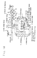
- FIG.1A shows a configuration of a diesel engine system 1 according to an embodiment of the present invention.
- the diesel engine system 1 includes a diesel engine 2, an intake path 3, an exhaust path 4, a turbo charger 5, an exhaust gas processor 6 and an EGR path 7.
- the intake path 3 is connected to an intake port 2a of the diesel engine 2
- the exhaust path 4 is connected to an exhaust port 2b of the diesel engine 2.
- the turbo charger 5 is driven by exhaust gas exhausted to the exhaust path 4 from the diesel engine 2 and compresses intake air.
- the exhaust gas processor 6 removes pollutant, such as NOx and PM, from the exhaust gas.
- the EGR path 7 is provided to connect the exhaust port 2b and the intake port 2a.
- the intake path 3 is provided with a compressor wheel 5a of the turbo charger 5, an intercooler 11 and a throttle valve 12.
- the intake air compressed by the turbo charger 5 is cooled by the intercooler 11 and then supplied through the throttle valve 12 to the diesel engine 2.
- the throttle valve 12 is used to control the flow rate of the intake air.
- the exhaust path 4 is provided with a VGT (Variable Geometry Turbocharger) actuator 13 and a turbine wheel 5b of the turbo charger 5.
- VGT Very Geometry Turbocharger
- the VGT actuator 13 is used to control the flow rate of the exhaust gas introduced to the turbine wheel 5b of the turbo charger 5.
- the turbine wheel 5b is driven by the introduced exhaust gas and drives the compressor wheel 5a provided in the intake path 3.
- the exhaust gas exhausted from the turbine wheel 5b of the turbo charger 5 is introduced into the exhaust gas processor 6.
- the exhaust gas processor 6 includes a reducing agent injector 14, a DOC (Diesel Oxidation Catalyst) 15, an LNT (Lean NOx Trap) 16 and a DPF (Diesel Particulate Filer) 17.
- the reducing agent injector 14 injects reducing agent into the exhaust gas to reduce it.
- the DOC 15, the LNT 16 and the DPF 17 are used to remove NOx and particulate matter (PM) from the exhaust gas.
- the exhaust gas is recirculated along the EGR path 7 from the exhaust port 2b to the intake port 2a to reduce the discharge of NOx to the external.
- the EGR path 7 is provided with an EGR cooler 18 and an EGR valve 19.
- the EGR cooler 18 cools the recirculated exhaust gas.
- the EGR valve 19 controls flow rate of the recirculated exhaust gas.
- the diesel engine 2 is provided with an engine speed sensor 21 for measuring its engine speed (number of revolutions) N.
- the intake path 3 is provided with an air flow meter 22 for measuring an intake air flow rate G air (namely, the flow rate of the intake air in the intake path 3).
- the air flow meter 22 is positioned upstream from the turbo charger 5.
- the intake port 2a is provided with an intake air pressure sensor 23 and an intake air temperature sensor 24, and the exhaust path 4 is provided with an air fuel ratio sensor 25 and a NOx sensor 26.
- the exhaust gas processor 6 is provided with exhaust gas temperature sensors 27a to 27d and a DPF differential pressure sensor 28 and a NOx sensor 29.
- output signals of the engine speed sensor 21, the air flow meter 22, the intake air pressure sensor 23, the intake air temperature sensor 24, the air fuel ratio sensor 25, the NOx sensor 26, the exhaust gas temperature sensors 27a to 27d, the DPF differential pressure sensor 28 and the NOx sensor 29 are supplied to a controller 8.
- the controller 8 controls the openings of the throttle valve 12, the VGT actuator 13, the reducing agent injector 14 and the EGR valve 19 based on the output signals.
- the control of the throttle valve 12 and the EGR valve 19 has influence on the production of the nitrogen oxide and the smoke (or the particulate matter).
- One feature of the diesel engine system 1 according to the present embodiment is that the appropriate control for the throttle valve 12 and the EGR valve 19 effectively suppresses the production of the smoke during the increase in the load of the engine without inhibiting the reduction of the nitrogen oxide.
- the throttle valve 12 and the EGR valve 19 are controlled such that response speeds are different when their openings are increased and when their openings are decreased.
- the throttle valve 12 when its opening x T/V is decreased, the decrease in the opening x T/V is started after the opening x T/V is held constant for a predetermined holding time.
- the opening x T/V is increased, the opening x T/V is immediately increased (without waiting for the elapse of the holding time).
- the EGR valve 19 when its opening x EGR is increased, the increase in the opening x EGR is started after the opening x EGR is held constant for the predetermined holding time.
- the opening x EGR is decreased, the opening x EGR is immediatelymade to decrease (without waiting for the elapse of the holding time).
- the production of smoke is effectively suppressed during the increase in the load of the diesel engine 2 without inhibiting the reduction of nitrogen oxide.
- the opening of the EGR valve 19 is finally increased in order to suppress the production of the nitrogen oxide, and the opening of the throttle valve 12 is decreased as necessary in addition to the increase in the opening of the EGR valve 19.
- the increase in the opening of the EGR valve 19 or the decrease in the opening of the throttle valve 12 induces the decrease in the flow rate of the intake air from the external. Thus, this may cause imperfect combustion which produces smoke.
- the openings of the throttle valve 12 and the EGR valve 19 are held constant for the predetermined holding time.
- the opening of the throttle valve 12 is immediately increased (without waiting for the elapse of the holding time), and the opening of the EGR valve 19 is decreased as necessary in addition to the increase in the opening of the throttle valve 12.
- the excess air ratio is optimally controlled, resulting in the suppression of the production of smoke.
- the holding time for the opening x T/V of the throttle valve 12 and the opening x EGR of the EGR valve 19 is preferably from one second to five seconds.
- the holding time for the opening x T/V of the throttle valve 12 and the opening x EGR of the EGR valve 19 is too short, the necessary flow rate of the intake air is not secured during the increase in the load of the diesel engine 2.
- the holding time for the opening x T/V of the throttle valve 12 and the opening x EGR of the EGR valve 19 is too long, undesired increase in the production of the nitrogen oxide occurs.
- FIG.3 shows the control logic for the openings of the throttle valve 12 and the EGR valve 19.
- the logic is executed in the controller 8.
- a torque command T* and the engine speed N measured by the engine speed sensor 21 are given to the controller 8.
- the torque command T* is a signal designating a torque to be outputted by the diesel engine 2.
- the torque command T* may be generated, for example, from an accelerator signal generated in response to the motion of an accelerator pedal or an injection quantity command designating an injection quantity of fuel. Also, the accelerator signal or the injection quantity command may be used in place of the torque command T*.
- the intake air flow rate G air measured by the air flow meter 22 is given to the controller 8.
- the intake air flow rate G air is obtained by the air flow meter 22.
- the intake air flow rate G air is used to control the openings of the throttle valve 12 and the EGR valve 19.
- Low pass filtering processes 31 and 33 are applied to the engine speed N and the torque command T*, respectively. Moreover, a desired value G air * of the flow rate of the intake air which flows in the intake path 3 is determined from the engine speed N and the torque command T* to which the low pass filtering processes are applied. A control map 33 is used to determine the desired value G air *.
- FIG.4 is a graph showing the control map 33.
- the control map 33 describes the corresponding relation between the desired value G air * and the combination of the engine speed N and the torque command T*.
- the control map 33 defines that the desired value G air * increases as the engine speed N increases or as the torque command T* increases.
- an error e between the determined desired value G air * and the intake air flow rate G air measured by the air flow meter 22 is calculated through a subtracting process 34, and a PID (Proportional-Integral-Derivative) control 35 is executed based on the error e.
- a control parameter ⁇ is determined through the PID control 35.
- the control parameter ⁇ is used for determining the opening x T/V of the throttle valve 12 and the opening x EGR of the EGR valve 19. As the load of the engine increases, the desired value G air * increases, and thus, the control parameter ⁇ decreases.
- the intake air flow rate G air is the parameter corresponding to the excess air ratio of the diesel engine 2.
- the control of the openings of the throttle valve 12 and the EGR valve 19 in response to the intake air flow rate G air is equivalent to the control of the openings of the throttle valve 12 and the EGR valve 19 in response to the excess air ratio of the diesel engine 2.
- the excess air ratio of the diesel engine 2 may be used in place of the intake air flow rate G air .
- the control map 33 describes the corresponding relation between a desired value of the excess air ratio and the combination of the engine speed N and the torque command T*. Then, the PID control 35 is executed based on an error e between the excess air ratio of the diesel engine 2 and the desired value of the excess air ratio.
- the controller 8 stores a function 37 for determining the opening x T/V of the throttle valve 12 from the control parameter ⁇ and a function 38 for determining the opening x EGR of the EGR valve 19 from the control parameter ⁇ .
- the controller 8 uses the functions 37 and 38 to determine the opening x T/V of the throttle valve 12 and the opening x EGR of the EGR valve 19.
- FIG.5 is a graph showing the relation between the control parameter ⁇ and the opening x T/V of the throttle valve 12 prescribed by the function 37 and the relation between the control parameter ⁇ and the opening x EGR of the EGR valve 19 prescribed by the function 38.
- the opening x T/V of the throttle valve 12 is controlled to a constant value x 0 (%) when the control parameter ⁇ is a minute value ⁇ 0 or less.
- the opening x T/V is made to monotonically increase from x 0 % to 100 % as ⁇ increases.
- ⁇ is 1 or more
- the opening x T/V is held at 100 %.
- the opening x EGR of the EGR valve 19 is held at 100 %, when the control parameter ⁇ is 1 or less.
- ⁇ is 1 or more, the opening x EGR is made to monotonically decrease from 100 % to 0 % as ⁇ increases.
- control parameter ⁇ calculated through the PID control 35 is not used directly for the determination of the opening x T/V of the throttle valve 12 and the opening x EGR of the EGR valve 19 through the functions 37 and 38.
- the controller 8 applies delay logic 36 to the control parameter ⁇ and applies the functions 37 and 38 to the control parameter ⁇ to which the delay logic 36 is applied to determine the opening x T/V of the throttle valve 12 and the opening x EGR of the EGR valve 19.
- the control parameter ⁇ to which the delay logic 36 has been applied is referred to as a control parameter ⁇ d .
- the delay logic 36 is used to execute the control in which the openings of the throttle valve 12 and the EGR valve 19 are decreased or increased after the elapse of the predetermined holding time.
- the delay logic 36 is determined as follows. When the control parameter ⁇ is decreased, the control parameter ⁇ d is decreased to follow the decrease of the control parameter ⁇ after the control parameter ⁇ d is held constant for the predetermined holding time. The decreasing rate of the control parameter ⁇ d is limited to a predetermined range.
- the opening x T/V is held constant for the predetermined holding time when the opening x T/V of the throttle valve 12 is decreased
- the opening x EGR is held constant for the predetermined holding time when the opening x EGR of the EGR valve 19 is increased.
- the control parameter ⁇ is increased, the control parameter ⁇ d is determined to be equal to the control parameter ⁇ .
- the opening x T/V is increased immediately (without waiting for the elapse of the holding time) when opening x T/V of the throttle valve 12 is increased, and the opening x EGR is decreased immediately (without waiting for the elapse of the holding time) when the opening x EGR of the EGR valve 19 is decreased. According to such control, the production of smoke is effectively suppressed during the increase in the load of the engine without inhibiting the reduction of the nitrogen oxide as described above.
- control is executed in which the openings of both the throttle valve 12 and the EGR valve 19 are decreased or increased after the elapse of the predetermined holding time.
- a control can be executed in which only one of the openings of the throttle valve 12 and the EGR valve 19 is decreased or increased after the elapse of the predetermined holding time.
- the decrease in the opening x T/V is started after the opening x T/V is held constant for the predetermined holding time when the opening x T/V of the throttle valve 12 is decreased, the opening x T/V is increased immediately (without waiting for the elapse of the holding time) when the opening x T/V is increased.
- the opening x EGR is decreased and increased without waiting for the elapse of the holding time.
- Such operation can be implemented, for example, by applying the function 37 to the control parameter ⁇ d to which the delay logic 36 is applied to calculate the opening x T/V of the throttle valve 12 and by applying the function 38 to the control parameter ⁇ (to which the delay logic 36 is not applied) to calculate the opening x EGR of the EGR valve 19. Also in such control, the necessary flow rate of the intake air is secured during the increase in the load while suppressing the production of smoke.
- the increase in the opening x EGR is started after the opening x EGR is held constant for the predetermined holding time when the opening x EGR of theEGRvalve 19 is increased, the opening x EGR is decreased immediately (without waiting for the elapse of the holding time) when the opening x EGR is decreased.
- the opening x T/V is decreased and increased without waiting for the elapse of the holding time.
- Such operation can be implemented, for example, by applying the function 37 to the control parameter ⁇ (to which the delay logic 36 is not applied) to calculate the opening x T/V of the throttle valve 12 and by applying the function 38 to the control parameter ⁇ d to which the delay logic 36 is applied to calculate the opening x EGR of the EGR valve 19.
- the holding time for the opening x T/V of the throttle valve 12 and the holding time for the opening x EGR of the EGR valve 19 may be different. Such control can be implemented when the holding time in the delay logic 36 applied with respect to the opening x T/V of the throttle valve 12 is different from that in the delay logic 36 applied with respect to the opening x EGR of the EGR valve 19.
- Figs. 6A to 6E are graphs showing the effectiveness of applying the delay logic 36 for the determination of the opening x T/V of the throttle valve 12 and the opening x EGR of the EGR valve 19.
- Figs. 6A to 6E show responses of the diesel engine system 1 according to the present embodiment when the load of the diesel engine 2 increases.
- the holding times for the opening x T/V of the throttle valve 12 and the opening x EGR of the EGR valve 19 are set to 4 seconds.
- FIG. 6A shows change in the engine speed of the diesel engine 2
- FIG. 6A shows change in the engine speed of the diesel engine 2
- FIG. 6B shows change in the output torque of the diesel engine 2
- FIG.6C shows change in the intake air flow rate
- FIG.6D shows change in the oxygen concentration in the exhaust gas
- FIG.6E shows change in opacity of the exhaust gas.
- the oxygen concentration in the exhaust gas shown in FIG. 6D corresponds to the oxygen quantity used for the combustion in the diesel engine 2
- a low oxygen concentration in the exhaust gas implies that an imperfect combustion occurs.
- the opacity shown in FIG.6E corresponds to the production of smoke, and a high opacity implies that smoke is being produced.
- the intake air f low rate G air increases.
- the opening of the EGR valve 19 is increased to suppress the production of nitrogen oxide and the opening of the throttle valve 12 is decreased. Consequently, the increase in the intake air flow rate G air is delayed.
- the delay of the increase in the intake air flow rate G air causes an imperfect combustion in the diesel engine 2 as shown in FIG.6D and a production of smoke for a long time as shown in FIG.6E .
- the production of smoke for a long time implies that the opacity of the exhaust gas continues to be high for a long time.
- the intake air flow rate G air is increased rapidly.
- the intake air flow rate G air is increased rapidly in all cases where the delay logic 36 is applied either to the determination of the opening x T/V of the throttle valve 12 only, to the determination of the opening x EGR of the EGR valve 19 only, or to both of them. Since the intake air flow rate G air is increased rapidly, as shown in FIG.6D , the imperfect combustion in the diesel engine 2 is prevented and the production of smoke is suppressed. The suppression of the production of smoke implies that the opacity of the exhaust gas is high during a short duration.
- FIG.7 shows another example of the control logic executed by the controller 8.
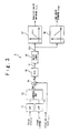
- a saturation calculation 39 is added to the control logic, said calculation corresponding to saturations (namely, a fully opened position and a fully closed position) in the throttle valve 12 and the EGR valve 19.
- the saturation calculation 39 is applied to the control parameter ⁇ d to which the delay logic 36 is applied to calculate a control parameter ⁇ s .
- control parameter ⁇ s is set equal to the control parameter ⁇ d when the control parameter ⁇ d is from 0 to 2, the control parameter ⁇ s is set to 0 when the control parameter ⁇ d is 0 or less, the control parameter ⁇ s is set to 2 when the control parameter ⁇ d is 2 or more. Then, the functions 37 and 38 are applied to the control parameter ⁇ s to calculate the opening x T/V of the throttle valve 12 and the opening x EGR of the EGR valve 19.
- the delay logic 36 is applied to the control parameter ⁇ to obtain the control parameter ⁇ d
- the saturation calculation 39 is applied to the control parameter ⁇ d to obtain the control parameter ⁇ s
- an anti-windup compensation 41 is executed based on the control parameter ⁇ s .
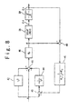
- FIG.8 is a control block diagram showing the PID control 35 and the anti-windup compensation 41.
- the error e the error e, a result of differentiation 42 and a result of integration 44 are added to obtain a sum, and a multiplication 46 is executed in which the sum is multiplied by a proportional gain K p .
- the integration 44 is applied to the error e from which a result of the anti-windup compensation 41 is subtracted.
- the difference is calculated between the control parameter ⁇ which is obtained through the PID control 35 (in the preceding control step one step before the present control step) and the control parameter ⁇ s which is obtained through the saturation calculation 39 (in the preceding control step).
- the anti-windup compensation 41 is executed based on the difference.
- the following equation can be used as a transfer function F AWU (s) of the anti-windup compensation 41.
- F AWU S 1 K P ⁇ T D ⁇ s + k P
- K P is the proportional gain of the PID control 35
- T D is the derivative time of the PID control 35.
- the anti-windup compensation 41 prevents the windup to make the response of the control worse.
- the anti-windup compensation 41 is effective, not only in the case that the PID control 35 is executed as described in the present embodiment, but also in the case that a PI (Proportional-Integral) control is executed in place of the PID control 35.
- PI Proportional-Integral
- the control parameter ⁇ is determined through the feedback control based on the intake air flow rate G air .
- the feedforward control since the opening x T/V of the throttle valve 12 and the opening x EGR of the EGR valve 19 are controlled in a short time after the start of change of the load of the diesel engine 2, the production of the smoke is more conspicuous than in the feedback control.
- the control is especially effective in which the opening of x T/V of the throttle valve 12 and the opening x EGR of the EGR valve 19 are increased or decreased after the predetermined holding time.
- the engine speed N and the torque command T* are given to the controller 8, and low pass filtering processes 31 and 33 are executed on the engine speed N and the torque command T*.
- the control parameter ⁇ is determined by using a control map 33A from the engine speed N and the torque command T* on which the low pass filtering processes are executed.
- the control map 33A describes the corresponding relation between the control parameter ⁇ and the combination of the engine speed N and the torque command T*.
- the control map 33A defines that the control parameter ⁇ decreases as the engine speed N increases or as the torque command T* increases.
- the delay logic 36 is applied to the control parameter ⁇ obtained by using the control map 33A to calculate the control parameter ⁇ d .
- the functions 37 and 38 are applied to the control parameter ⁇ d (to which the delay logic 36 is applied) to determine the opening x T/V of the throttle valve 12 and the opening x EGR of the EGR valve 19.
- the function 37 is used for determining the opening x T/V of the throttle valve 12 from the control parameter ⁇ d
- the function 38 is used for determining the opening x EGR of the EGR valve 19 from the control parameter ⁇ d .
- the application of the delay logic 36 can effectively suppress the production of smoke during the increase in the load of the engine without inhibiting the reduction of nitrogen oxide.
- the control parameter ⁇ is decreased, the control parameter ⁇ d is decreased to follow the decrease in the control parameter ⁇ after the control parameter ⁇ d has been held constant for the predetermined holding time. Since the control parameter ⁇ d is held constant for the predetermined holding time when the control parameter ⁇ decreases, the opening x T/V is held constant for the predetermined holding time when the opening x T/V of the throttle valve 12 is decreased, and in addition, the opening x EGR is held constant for the predetermined holding time when the opening x EGR of the EGR valve 19 is increased.
- the control parameter ⁇ d is determined to be equal to the control parameter ⁇ . Consequently, the opening x T/V is increased immediately (without waiting for the elapse of the holding time) when opening x T/V of the throttle valve 12 is increased, and the opening x EGR is decreased immediately (without waiting for the elapse of the holding time) when the opening x EGR of the EGR valve 19 is decreased. According to such control, the production of smoke is effectively suppressed during the increase in the load of the engine without inhibiting the reduction of the nitrogen oxide as described above.
- the holding time is preferably longer than in the case where the feedback control of FIG.3 is executed.
- the intake air flow rate (or the excess air ratio) is detected, and the throttle valve 12 and the EGR valve 19 are controlled based on the intake air flow rate (or the excess air ratio).
- the intake air flow rate (or the excess air ratio) is not considered for controlling the throttle valve 12 and the EGR valve 19.
- the holding time is preferably set to be longer than in the case where the feedback control of FIG.3 is executed.
- the holding times for the opening x T/V of the throttle valve 12 and the opening x EGR of the EGR valve 19 are preferably from 1 second to 10 seconds, and more preferably from 3 second to 10 seconds.
- the holding times of the opening x T/V of the throttle valve 12 and the opening x EGR of the EGR valve 19 are too short, the necessary flow rate of the intake air is not secured during the increase in the load of the diesel engine 2.
- the holding times of the opening x T/V of the throttle valve 12 and the opening x EGR of the EGR valve 19 are too long, undesired increase in the production of the nitrogen oxide occurs.
Landscapes
- Engineering & Computer Science (AREA)
- Chemical & Material Sciences (AREA)
- Combustion & Propulsion (AREA)
- Mechanical Engineering (AREA)
- General Engineering & Computer Science (AREA)
- Exhaust-Gas Circulating Devices (AREA)
- Output Control And Ontrol Of Special Type Engine (AREA)
- Control Of Throttle Valves Provided In The Intake System Or In The Exhaust System (AREA)
Abstract
Description
- The present invention relates to a diesel engine system, and more particularly relates to reducing pollutant such as NOx (nitrogen oxide) and PM (Particulate Matter) in exhaust gas from a diesel engine.
- Exhaust gas recirculation (EGR) in which exhaust gas from a diesel engine is partially recirculated to an intake pipe is known as one of the methods used to reduce nitrogen oxide in the exhaust gas. The exhaust gas includes no oxygen or oxygen of low concentration. Thus, when the exhaust gas is recirculated to the intake pipe, combustion is carried out in a state of low oxygen concentration. For this reason, a combustion temperature is decreased, thereby suppressing the production of NOx. The exhaust gas recirculation is disclosed in, for example, Japanese Patent No.
3448862 3092547 JP-A-Heisei, 11-50917 JP-A-Heisei, 11-280525 - A structure of a diesel engine that employs the exhaust gas recirculation is described schematically as follows. An EGR path (exhaust gas recirculation channel) is provided between an exhaust port and an intake port of the diesel engine. Along the EGR path, exhaust gas is recirculated to an intake path. An EGR valve (exhaust gas recirculation controlling valve) for controlling the flow rate of the recirculated exhaust gas is provided to the EGR path. In addition, a throttle valve (intake throttle valve) for controlling the flow rate of intake air is provided to the intake path.
- The openings of the EGR valve and the throttle valve are controlled such that an excess air ratio matches with a desired value. Specifically, when the excess air ratio is higher than the desired value, the opening of the EGR valve is increased, thereby causing the flow rate of the recirculated exhaust gas to increase. After the EGR valve is fully opened, the opening of the throttle valve is decreased. In such control, the flow rate of the recirculated exhaust gas is increased and the flow rate of external air as the intake air is decreased as necessary, and thus the excess air ratio is decreased to the desired value. On the other hand, when the excess air ratio is lower than the desired value, the opening of the throttle valve is increased. When the throttle valve is fully opened and the excess air ratio is still lower than the desired value, the opening of the EGR valve is decreased. In such control, the flow rate of the external air is increased and the flow rate of the recirculated exhaust gas is decreased as necessary, and thus the excess air ratio is increased to the desired value.
- In order to reduce nitrogen oxide effectively, it is important to control the openings of the EGR valve and the throttle valve based on the load of the diesel engine, because said openings to attain the desired excess air ratio vary depending on the load of the engine. Even when the opening of the EGR valve is constant, the flow rate of the recirculated exhaust gas varies depending on the load of the diesel engine, especially, on an engine speed of the engine (number of revolutions of the engine).
- Specifically, when the load of the diesel engine is small (namely, when the engine speed is low), the pressure of the intake air is low. Thus, the flow rate of the recirculated exhaust gas can be high even when the opening of the EGR valve is small. Therefore, when the load of the diesel engine is small, the opening of the EGR valve is made small, and the opening of the throttle valve is made large. On the other hand, when the load of the diesel engine is large, the opening of the EGR valve is required to be large to make the exhaust gas to be recirculated at a desired flow rate. Therefore, when the load of the diesel engine is large, the opening of the EGR valve is made large, or the opening of the throttle valve is made small. Such control can maximize the reduction of the nitrogen oxide.
- Such control can cause a problem in that much smoke is produced during the increase in the load of the diesel engine. In other words, much particulate matter is produced during the increase in the load. From the viewpoint of securing the flow rate of the recirculated exhaust gas to reduce nitrogen oxide, it is preferable to make the opening of the EGR valve increase as the load of the diesel engine increases. It is more preferable to make the opening of the throttle valve decrease as necessary in addition to the increase in the opening of the EGR valve. However, such control has an adverse effect that the necessary flow rate of the intake air is not secured during the increase in the load of the diesel engine. As the load of the diesel engine increases, the necessary flow rate of the intake air increases. However, the opening of the EGR valve is increased or the opening of the throttle valve is decreased in order to reduce nitrogen oxide, the external air supplied to the diesel engine is reduced, and thus the necessary flow rate of the intake air is not secured. In such case, incomplete combustion occurs in a combustion chamber of the diesel engine, and smoke is produced. Since the increase in the load of the diesel engine has an action to induce the increase in the flow rate of the intake air, after the end of the increase in the load of the diesel engine (namely, after the end of the increase in the engine speed), the problem of securing the necessary flow rate of the intake air is not critical. However, the action to induce the increase in the flow rate of the intake air is not effective during the increase in the load. Therefore, during the increase in the load, a critical problem occurs that when the opening of the EGR valve is increased or when the opening of the throttle valve is decreased, the necessary flow rate of the intake air is not secured and smoke is produced.
- In view of such background, it is required to suppress the production of the smoke during the increase in the load of the engine without inhibiting the reduction of the nitrogen oxide.
- Japanese Laid Open Patent Application (
JP-A-Heisei, 6-74070 - The air fuel ratio controller includes a first delay circuit and a second delay circuit. The first delay circuit averages a voltage signal which indicates oxygen concentration in the exhaust gas. The second delay circuit delays a difference signal between the averaged voltage signal and a desired value signal. The desired value signal is set based on temperature of the exhaust gas. The controller controls the bypass valve based on the delayed difference signal.
- An object of the present invention is to suppress the production of the smoke during the increase in the load of the engine without inhibiting the reduction of the nitrogen oxide.
- In one aspect of the present invention, a diesel engine system includes: a diesel engine; a throttle valve configured to control a flow rate of intake air to the diesel engine; an EGR (Exhaust Gas Recirculation) path along which exhaust gas is recirculated from an exhaust port to an intake port of the diesel engine; an EGR valve configured to control a flow rate of the exhaust gas; and a controller configured to control the throttle valve and the EGR valve such that an opening of the throttle valve decreases and an opening of the EGR valve increases when a load of the diesel engine increases. The controller is configured to control the EGR valve such that the opening of the EGR valve increases after the opening of the EGR valve is held constant for a first predetermined holding time.
- According to the above configuration, since the opening of the EGR valve is held constant for the first predetermined holding time, an action is not inhibited in which the increase in the load of the diesel engine induces the increase in the flow rate of the intake air. Therefore, in the diesel engine system, the necessary flow rate of the intake air is secured and the production of smoke is suppressed during the increase in the load of the diesel engine. Preferably, the first holding time is from 1 second to 5 seconds.
- In order to stop the production of smoke, the controller is preferably configured to control the throttle valve such that the opening of the throttle valve decreases after the opening of the throttle valve is held constant for a second predetermined holding time. Preferably, the second holding time is from 1 second to 5 seconds.
- When the diesel engine system is provided with an air flow meter which measures the flow rate of the intake air, it is preferable that a desired value of the flow rate of the intake air is determined from the load and that the openings of the throttle valve and the EGR valve are determined through a feedback control based on an error between the desired value and a measured value of the flow rate of the intake air obtained by the air flow meter.
- Specifically, it is preferable that a first control parameter is determined through a PID (Proportional-Integral-Derivative) or PI (Proportional-Integral) control based on the error, that a second control parameter is determined by applying a delay logic to the first control parameter, that a third control parameter is determined by applying a saturation calculation to the second control parameter and that the openings of the throttle valve and the EGR valve are determined from the third control parameter. In this case, the delay logic is defined so that the second control parameter is held for the first holding time when the opening of the EGR valve is increased. An anti-windup correlation is preferably executed on the PID or PI control to improve the response of the control. The anti-windup correlation is executed based on a difference between the first control parameter and the third control parameter.
- It is also preferable that the openings of the throttle valve and EGR valve are determined through a feedforward control based on the load of the diesel engine. When the feedforward control is executed, the control is especially effective in which the opening of the EGR valve is increased after the opening of the EGR valve is held constant for the first predetermined holding time.
- In another aspect of the present invention, a diesel engine system includes: a diesel engine; a throttle valve configured to control a flow rate of intake air to the diesel engine; an EGR (Exhaust Gas Recirculation) path along which exhaust gas is recirculated from an exhaust port to an intake port of the diesel engine; an EGR valve configured to control a flow rate of the exhaust gas; and a controller configured to control the throttle valve and the EGR valve such that an opening of the throttle valve decreases and an opening of the EGR valve increases when a load of the diesel engine increases. The controller is configured to control the throttle valve such that the opening of the throttle valve decreases after the opening of the throttle valve is held constant for a predetermined holding time.
- According to the above configuration, since the opening of the throttle valve is held constant for the predetermined holding time, an action is not inhibited in which the increase in the load of the diesel engine induces the increase in the flow rate of the intake air. Therefore, in the diesel engine system, the necessary flow rate of the intake air is secured and the production of smoke is prevented during the increase in the load of the diesel engine.
-
-
FIG.1A shows a configuration of a diesel engine system according to an embodiment of the present invention; -
FIG.1B is a block diagram showing a configuration of a control system of the diesel engine system ofFIG.1A ; -
FIG.2A is a graph showing an example of a change in an opening of a throttle valve; -
FIG.2B is a graph showing an example of a change in an opening of an EGR valve; -
FIG.3 is a block diagram showing an example of a control logic executed by a controller; -
FIG.4 is a conceptual illustration showing a control map used in the control logic ofFIG.3 ; -
FIG.5 is a graph showing functions used in the control logic ofFIG.3 ; -
FIG.6A is a graph showing a change in engine speed when a control is executed in which the opening of the throttle valve and/or the opening of the EGR valve is held constant during a predetermined holding time; -
FIG.6B is a graph showing a change in torque when the control is executed; -
FIG.6C is a graph showing a change in flow rate of intake air when the control is executed; -
FIG.6D is a graph showing a change in oxygen concentration in exhaust gas when the control is executed; -
FIG.6E is a graph showing a change in opacity of the exhaust gas when the control is executed; -
FIG.7 is a block diagram showing another example of the control logic executed by the controller; -
FIG.8 is a block diagram showing an example of an anti-windup compensation executed in the control logic ofFIG.7 ; and -
FIG.9 is a block diagram showing another example of the control logic executed by the controller. -
FIG.1A shows a configuration of adiesel engine system 1 according to an embodiment of the present invention. Thediesel engine system 1 includes adiesel engine 2, anintake path 3, an exhaust path 4, aturbo charger 5, anexhaust gas processor 6 and anEGR path 7. Theintake path 3 is connected to anintake port 2a of thediesel engine 2, and the exhaust path 4 is connected to anexhaust port 2b of thediesel engine 2. Theturbo charger 5 is driven by exhaust gas exhausted to the exhaust path 4 from thediesel engine 2 and compresses intake air. Theexhaust gas processor 6 removes pollutant, such as NOx and PM, from the exhaust gas. TheEGR path 7 is provided to connect theexhaust port 2b and theintake port 2a. - The
intake path 3 is provided with acompressor wheel 5a of theturbo charger 5, anintercooler 11 and athrottle valve 12. The intake air compressed by theturbo charger 5 is cooled by theintercooler 11 and then supplied through thethrottle valve 12 to thediesel engine 2. Thethrottle valve 12 is used to control the flow rate of the intake air. - The exhaust path 4 is provided with a VGT (Variable Geometry Turbocharger)
actuator 13 and aturbine wheel 5b of theturbo charger 5. TheVGT actuator 13 is used to control the flow rate of the exhaust gas introduced to theturbine wheel 5b of theturbo charger 5. Theturbine wheel 5b is driven by the introduced exhaust gas and drives thecompressor wheel 5a provided in theintake path 3. Thus, the intake air in theintake path 3 is compressed. The exhaust gas exhausted from theturbine wheel 5b of theturbo charger 5 is introduced into theexhaust gas processor 6. - The
exhaust gas processor 6 includes a reducingagent injector 14, a DOC (Diesel Oxidation Catalyst) 15, an LNT (Lean NOx Trap) 16 and a DPF (Diesel Particulate Filer) 17. The reducingagent injector 14 injects reducing agent into the exhaust gas to reduce it. TheDOC 15, theLNT 16 and theDPF 17 are used to remove NOx and particulate matter (PM) from the exhaust gas. - The exhaust gas is recirculated along the
EGR path 7 from theexhaust port 2b to theintake port 2a to reduce the discharge of NOx to the external. TheEGR path 7 is provided with anEGR cooler 18 and anEGR valve 19. TheEGR cooler 18 cools the recirculated exhaust gas. TheEGR valve 19 controls flow rate of the recirculated exhaust gas. - In order to properly control the
throttle valve 12, theVGT actuator 13, the reducingagent injector 14 and theEGR valve 19, various measuring instruments and sensors are provided at the respective positions of thediesel engine system 1. Specifically, thediesel engine 2 is provided with anengine speed sensor 21 for measuring its engine speed (number of revolutions) N. Theintake path 3 is provided with anair flow meter 22 for measuring an intake air flow rate Gair (namely, the flow rate of the intake air in the intake path 3). Theair flow meter 22 is positioned upstream from theturbo charger 5. In addition, theintake port 2a is provided with an intakeair pressure sensor 23 and an intakeair temperature sensor 24, and the exhaust path 4 is provided with an airfuel ratio sensor 25 and aNOx sensor 26. Moreover, theexhaust gas processor 6 is provided with exhaustgas temperature sensors 27a to 27d and a DPFdifferential pressure sensor 28 and aNOx sensor 29. - As shown in
FIG. 1B , output signals of theengine speed sensor 21, theair flow meter 22, the intakeair pressure sensor 23, the intakeair temperature sensor 24, the airfuel ratio sensor 25, theNOx sensor 26, the exhaustgas temperature sensors 27a to 27d, the DPFdifferential pressure sensor 28 and theNOx sensor 29 are supplied to acontroller 8. Thecontroller 8 controls the openings of thethrottle valve 12, theVGT actuator 13, the reducingagent injector 14 and theEGR valve 19 based on the output signals. - As mentioned above, the control of the
throttle valve 12 and theEGR valve 19 has influence on the production of the nitrogen oxide and the smoke (or the particulate matter). One feature of thediesel engine system 1 according to the present embodiment is that the appropriate control for thethrottle valve 12 and theEGR valve 19 effectively suppresses the production of the smoke during the increase in the load of the engine without inhibiting the reduction of the nitrogen oxide. - Specifically, in the
diesel engine system 1 according to the present embodiment, thethrottle valve 12 and theEGR valve 19 are controlled such that response speeds are different when their openings are increased and when their openings are decreased. Specifically, as shown inFIG.2A , as for thethrottle valve 12, when its opening xT/V is decreased, the decrease in the opening xT/V is started after the opening xT/V is held constant for a predetermined holding time. When the opening xT/V is increased, the opening xT/V is immediately increased (without waiting for the elapse of the holding time). On the other hand, as for theEGR valve 19, as shown inFIG.2B , when its opening xEGR is increased, the increase in the opening xEGR is started after the opening xEGR is held constant for the predetermined holding time. When the opening xEGR is decreased, the opening xEGR is immediatelymade to decrease (without waiting for the elapse of the holding time). - According to such control, the production of smoke is effectively suppressed during the increase in the load of the
diesel engine 2 without inhibiting the reduction of nitrogen oxide. When the load of thediesel engine 2 increases, the opening of theEGR valve 19 is finally increased in order to suppress the production of the nitrogen oxide, and the opening of thethrottle valve 12 is decreased as necessary in addition to the increase in the opening of theEGR valve 19. The increase in the opening of theEGR valve 19 or the decrease in the opening of thethrottle valve 12 induces the decrease in the flow rate of the intake air from the external. Thus, this may cause imperfect combustion which produces smoke. However, in the present embodiment, the openings of thethrottle valve 12 and theEGR valve 19 are held constant for the predetermined holding time. Thus, during the increase in the load of thediesel engine 2, the action in which the increase in the load of thediesel engine 2 induces the increase in the flow rate of the intake air is unlikely to be inhibited. Hence, it is possible that the necessary flow rate of the intake air is secured and the production of smoke is suppressed even during the increase in the load. - On the other hand, when the load of the
diesel engine 2 decreases, the opening of thethrottle valve 12 is immediately increased (without waiting for the elapse of the holding time), and the opening of theEGR valve 19 is decreased as necessary in addition to the increase in the opening of thethrottle valve 12. Thus, the excess air ratio is optimally controlled, resulting in the suppression of the production of smoke. - The holding time for the opening xT/V of the
throttle valve 12 and the opening xEGR of theEGR valve 19 is preferably from one second to five seconds. When the holding time for the opening xT/V of thethrottle valve 12 and the opening xEGR of theEGR valve 19 is too short, the necessary flow rate of the intake air is not secured during the increase in the load of thediesel engine 2. On the other hand, when the holding time for the opening xT/V of thethrottle valve 12 and the opening xEGR of theEGR valve 19 is too long, undesired increase in the production of the nitrogen oxide occurs. - The specific control logic to execute the above control will be described below.
FIG.3 shows the control logic for the openings of thethrottle valve 12 and theEGR valve 19. The logic is executed in thecontroller 8. A torque command T* and the engine speed N measured by theengine speed sensor 21 are given to thecontroller 8. The torque command T* is a signal designating a torque to be outputted by thediesel engine 2. When thediesel engine system 1 is installed in a vehicle, the torque command T* may be generated, for example, from an accelerator signal generated in response to the motion of an accelerator pedal or an injection quantity command designating an injection quantity of fuel. Also, the accelerator signal or the injection quantity command may be used in place of the torque command T*. - Moreover, the intake air flow rate Gair measured by the
air flow meter 22 is given to thecontroller 8. The intake air flow rate Gair is obtained by theair flow meter 22. The intake air flow rate Gair is used to control the openings of thethrottle valve 12 and theEGR valve 19. - Low pass filtering processes 31 and 33 are applied to the engine speed N and the torque command T*, respectively. Moreover, a desired value Gair* of the flow rate of the intake air which flows in the
intake path 3 is determined from the engine speed N and the torque command T* to which the low pass filtering processes are applied. Acontrol map 33 is used to determine the desired value Gair*. -
FIG.4 is a graph showing thecontrol map 33. Thecontrol map 33 describes the corresponding relation between the desired value Gair* and the combination of the engine speed N and the torque command T*. Thecontrol map 33 defines that the desired value Gair* increases as the engine speed N increases or as the torque command T* increases. - Moreover, an error e between the determined desired value Gair* and the intake air flow rate Gair measured by the
air flow meter 22 is calculated through a subtractingprocess 34, and a PID (Proportional-Integral-Derivative)control 35 is executed based on the error e. A control parameter θ is determined through thePID control 35. The control parameter θ is used for determining the opening xT/V of thethrottle valve 12 and the opening xEGR of theEGR valve 19. As the load of the engine increases, the desired value Gair* increases, and thus, the control parameter θ decreases. - The intake air flow rate Gair is the parameter corresponding to the excess air ratio of the
diesel engine 2. Thus, the control of the openings of thethrottle valve 12 and theEGR valve 19 in response to the intake air flow rate Gair is equivalent to the control of the openings of thethrottle valve 12 and theEGR valve 19 in response to the excess air ratio of thediesel engine 2. Thus, the excess air ratio of thediesel engine 2 may be used in place of the intake air flow rate Gair. In this case, thecontrol map 33 describes the corresponding relation between a desired value of the excess air ratio and the combination of the engine speed N and the torque command T*. Then, thePID control 35 is executed based on an error e between the excess air ratio of thediesel engine 2 and the desired value of the excess air ratio. - The
controller 8 stores afunction 37 for determining the opening xT/V of thethrottle valve 12 from the control parameter θ and afunction 38 for determining the opening xEGR of theEGR valve 19 from the control parameter θ. Thecontroller 8 uses thefunctions throttle valve 12 and the opening xEGR of theEGR valve 19.FIG.5 is a graph showing the relation between the control parameter θ and the opening xT/V of thethrottle valve 12 prescribed by thefunction 37 and the relation between the control parameter θ and the opening xEGR of theEGR valve 19 prescribed by thefunction 38. In the present embodiment, the opening xT/V of thethrottle valve 12 is controlled to a constant value x0 (%) when the control parameter θ is a minute value θ0 or less. When the control parameter θ is from θ0 to 1, the opening xT/V is made to monotonically increase from x0 % to 100 % as θ increases. When θ is 1 or more, the opening xT/V is held at 100 %. On the other hand, the opening xEGR of theEGR valve 19 is held at 100 %, when the control parameter θ is 1 or less. When θ is 1 or more, the opening xEGR is made to monotonically decrease from 100 % to 0 % as θ increases. - In the present embodiment, the control parameter θ calculated through the
PID control 35 is not used directly for the determination of the opening xT/V of thethrottle valve 12 and the opening xEGR of theEGR valve 19 through thefunctions controller 8 appliesdelay logic 36 to the control parameter θ and applies thefunctions delay logic 36 is applied to determine the opening xT/V of thethrottle valve 12 and the opening xEGR of theEGR valve 19. In the following explanation, the control parameter θ to which thedelay logic 36 has been applied is referred to as a control parameter θd. - The
delay logic 36 is used to execute the control in which the openings of thethrottle valve 12 and theEGR valve 19 are decreased or increased after the elapse of the predetermined holding time. Thedelay logic 36 is determined as follows. When the control parameter θ is decreased, the control parameter θd is decreased to follow the decrease of the control parameter θ after the control parameter θd is held constant for the predetermined holding time. The decreasing rate of the control parameter θd is limited to a predetermined range. Since the control parameter θd is held constant for the predetermined holding time when the control parameter θ decreases, the opening xT/V is held constant for the predetermined holding time when the opening xT/V of thethrottle valve 12 is decreased, in addition, the opening xEGR is held constant for the predetermined holding time when the opening xEGR of theEGR valve 19 is increased. On the other hand, when the control parameter θ is increased, the control parameter θd is determined to be equal to the control parameter θ. Consequently, the opening xT/V is increased immediately (without waiting for the elapse of the holding time) when opening xT/V of thethrottle valve 12 is increased, and the opening xEGR is decreased immediately (without waiting for the elapse of the holding time) when the opening xEGR of theEGR valve 19 is decreased. According to such control, the production of smoke is effectively suppressed during the increase in the load of the engine without inhibiting the reduction of the nitrogen oxide as described above. - In the above explanations, the control is executed in which the openings of both the
throttle valve 12 and theEGR valve 19 are decreased or increased after the elapse of the predetermined holding time. A control can be executed in which only one of the openings of thethrottle valve 12 and theEGR valve 19 is decreased or increased after the elapse of the predetermined holding time. - That is, in another embodiment, the decrease in the opening xT/V is started after the opening xT/V is held constant for the predetermined holding time when the opening xT/V of the
throttle valve 12 is decreased, the opening xT/V is increased immediately (without waiting for the elapse of the holding time) when the opening xT/V is increased. On the other hand, as for theEGR valve 19, the opening xEGR is decreased and increased without waiting for the elapse of the holding time. Such operation can be implemented, for example, by applying thefunction 37 to the control parameter θd to which thedelay logic 36 is applied to calculate the opening xT/V of thethrottle valve 12 and by applying thefunction 38 to the control parameter θ (to which thedelay logic 36 is not applied) to calculate the opening xEGR of theEGR valve 19. Also in such control, the necessary flow rate of the intake air is secured during the increase in the load while suppressing the production of smoke. - In still another embodiment, the increase in the opening xEGR is started after the opening xEGR is held constant for the predetermined holding time when the opening xEGR of
theEGRvalve 19 is increased, the opening xEGR is decreased immediately (without waiting for the elapse of the holding time) when the opening xEGR is decreased. On the other hand, as for thethrottle valve 12, the opening xT/V is decreased and increased without waiting for the elapse of the holding time. Such operation can be implemented, for example, by applying thefunction 37 to the control parameter θ (to which thedelay logic 36 is not applied) to calculate the opening xT/V of thethrottle valve 12 and by applying thefunction 38 to the control parameter θd to which thedelay logic 36 is applied to calculate the opening xEGR of theEGR valve 19. - The holding time for the opening xT/V of the
throttle valve 12 and the holding time for the opening xEGR of theEGR valve 19 may be different. Such control can be implemented when the holding time in thedelay logic 36 applied with respect to the opening xT/V of thethrottle valve 12 is different from that in thedelay logic 36 applied with respect to the opening xEGR of theEGR valve 19. -
Figs. 6A to 6E are graphs showing the effectiveness of applying thedelay logic 36 for the determination of the opening xT/V of thethrottle valve 12 and the opening xEGR of theEGR valve 19.Figs. 6A to 6E show responses of thediesel engine system 1 according to the present embodiment when the load of thediesel engine 2 increases. The holding times for the opening xT/V of thethrottle valve 12 and the opening xEGR of theEGR valve 19 are set to 4 seconds. In detail,FIG. 6A shows change in the engine speed of thediesel engine 2,FIG. 6B shows change in the output torque of thediesel engine 2,FIG.6C shows change in the intake air flow rate,FIG.6D shows change in the oxygen concentration in the exhaust gas, andFIG.6E shows change in opacity of the exhaust gas. The oxygen concentration in the exhaust gas shown inFIG. 6D corresponds to the oxygen quantity used for the combustion in thediesel engine 2, and a low oxygen concentration in the exhaust gas implies that an imperfect combustion occurs. On the other hand, the opacity shown inFIG.6E corresponds to the production of smoke, and a high opacity implies that smoke is being produced. - When the load of the
diesel engine 2 increases, the intake air f low rate Gair also increases. As for a comparison example in which thedelay logic 36 is not used, when the load of thediesel engine 2 increases, the opening of theEGR valve 19 is increased to suppress the production of nitrogen oxide and the opening of thethrottle valve 12 is decreased. Consequently, the increase in the intake air flow rate Gair is delayed. The delay of the increase in the intake air flow rate Gair causes an imperfect combustion in thediesel engine 2 as shown inFIG.6D and a production of smoke for a long time as shown inFIG.6E . The production of smoke for a long time implies that the opacity of the exhaust gas continues to be high for a long time. - On the other hand, as can be understood from
FIG.6C , when thedelay logic 36 according to the present invention is used, the intake air flow rate Gair is increased rapidly. The intake air flow rate Gair is increased rapidly in all cases where thedelay logic 36 is applied either to the determination of the opening xT/V of thethrottle valve 12 only, to the determination of the opening xEGR of theEGR valve 19 only, or to both of them. Since the intake air flow rate Gair is increased rapidly, as shown inFIG.6D , the imperfect combustion in thediesel engine 2 is prevented and the production of smoke is suppressed. The suppression of the production of smoke implies that the opacity of the exhaust gas is high during a short duration. - From
FIG.6C , it is understood that the application of thedelay logic 36 to both of the determinations of the opening xT/V of thethrottle valve 12 and the opening xEGR of theEGR valve 19 results in the most rapid increase in the intake air flow rate Gair. This indicates the effectiveness of the application of thedelay logic 36 for both of the opening xT/V of thethrottle valve 12 and the opening xEGR of theEGR valve 19. However, as can be understood fromFIGS.6A to 6E , it is also effective to apply thedelay logic 36 to only one of them. -
FIG.7 shows another example of the control logic executed by thecontroller 8. In the control logic ofFIG. 7 , asaturation calculation 39 is added to the control logic, said calculation corresponding to saturations (namely, a fully opened position and a fully closed position) in thethrottle valve 12 and theEGR valve 19. In the present embodiment, thesaturation calculation 39 is applied to the control parameter θd to which thedelay logic 36 is applied to calculate a control parameter θs. Specifically, the control parameter θs is set equal to the control parameter θd when the control parameter θd is from 0 to 2, the control parameter θs is set to 0 when the control parameter θd is 0 or less, the control parameter θs is set to 2 when the control parameter θd is 2 or more. Then, thefunctions throttle valve 12 and the opening xEGR of theEGR valve 19. - The problem occurs that the saturations in the
throttle valve 12 and theEGR valve 19 causes a windup. When thethrottle valve 12 or theEGR valve 19 is fully opened or fully closed, a control error continues to exist. On the other hand, since the error e used in thePID control 35 is held to a value other than 0, an integral value in thePID control 35 continues to increase to the extent that the response of the control becomes worse. When thedelay logic 36 is used, the problem of windup is conspicuous. - In order to effectively avoid the problem of windup, in the present embodiment, the
delay logic 36 is applied to the control parameter θ to obtain the control parameter θd, thesaturation calculation 39 is applied to the control parameter θd to obtain the control parameter θs, and ananti-windup compensation 41 is executed based on the control parameter θs. -
FIG.8 is a control block diagram showing thePID control 35 and theanti-windup compensation 41. In thePID control 35, the error e, a result ofdifferentiation 42 and a result ofintegration 44 are added to obtain a sum, and amultiplication 46 is executed in which the sum is multiplied by a proportional gain Kp. Here, theintegration 44 is applied to the error e from which a result of theanti-windup compensation 41 is subtracted. In asubtraction 40, the difference is calculated between the control parameter θ which is obtained through the PID control 35 (in the preceding control step one step before the present control step) and the control parameter θs which is obtained through the saturation calculation 39 (in the preceding control step). Theanti-windup compensation 41 is executed based on the difference. The following equation can be used as a transfer function FAWU(s) of theanti-windup compensation 41.
Here, KP is the proportional gain of thePID control 35, and TD is the derivative time of thePID control 35. Theanti-windup compensation 41 prevents the windup to make the response of the control worse. - The
anti-windup compensation 41 is effective, not only in the case that thePID control 35 is executed as described in the present embodiment, but also in the case that a PI (Proportional-Integral) control is executed in place of thePID control 35. - As shown in
FIG.3 andFIG.8 , the control parameter θ is determined through the feedback control based on the intake air flow rate Gair. As shown inFIG.9 , it is also possible to determine the control parameter θ through a feedforward control based on the load of thediesel engine 2. Namely, it is also possible to determine the opening xT/V of thethrottle valve 12 and the opening xEGR of theEGR valve 19 through the feedforward control. In the feedforward control, since the opening xT/V of thethrottle valve 12 and the opening xEGR of theEGR valve 19 are controlled in a short time after the start of change of the load of thediesel engine 2, the production of the smoke is more conspicuous than in the feedback control. Hence, when the feedforward control is executed, the control is especially effective in which the opening of xT/V of thethrottle valve 12 and the opening xEGR of theEGR valve 19 are increased or decreased after the predetermined holding time. - Specifically, the engine speed N and the torque command T* are given to the
controller 8, and low pass filtering processes 31 and 33 are executed on the engine speed N and the torque command T*. The control parameter θ is determined by using acontrol map 33A from the engine speed N and the torque command T* on which the low pass filtering processes are executed. Thecontrol map 33A describes the corresponding relation between the control parameter θ and the combination of the engine speed N and the torque command T*. Thecontrol map 33A defines that the control parameter θ decreases as the engine speed N increases or as the torque command T* increases. - The
delay logic 36 is applied to the control parameter θ obtained by using thecontrol map 33A to calculate the control parameter θd. Then, thefunctions delay logic 36 is applied) to determine the opening xT/V of thethrottle valve 12 and the opening xEGR of theEGR valve 19. Thefunction 37 is used for determining the opening xT/V of thethrottle valve 12 from the control parameter θd, and thefunction 38 is used for determining the opening xEGR of theEGR valve 19 from the control parameter θd. - Also in the control shown in
FIG.9 , the application of thedelay logic 36 can effectively suppress the production of smoke during the increase in the load of the engine without inhibiting the reduction of nitrogen oxide. In detail, when the control parameter θ is decreased, the control parameter θd is decreased to follow the decrease in the control parameter θ after the control parameter θd has been held constant for the predetermined holding time. Since the control parameter θd is held constant for the predetermined holding time when the control parameter θ decreases, the opening xT/V is held constant for the predetermined holding time when the opening xT/V of thethrottle valve 12 is decreased, and in addition, the opening xEGR is held constant for the predetermined holding time when the opening xEGR of theEGR valve 19 is increased. On the other hand, when the control parameter θ is increased, the control parameter θd is determined to be equal to the control parameter θ. Consequently, the opening xT/V is increased immediately (without waiting for the elapse of the holding time) when opening xT/V of thethrottle valve 12 is increased, and the opening xEGR is decreased immediately (without waiting for the elapse of the holding time) when the opening xEGR of theEGR valve 19 is decreased. According to such control, the production of smoke is effectively suppressed during the increase in the load of the engine without inhibiting the reduction of the nitrogen oxide as described above. - When the feedforward control of
FIG.9 is executed, the holding time is preferably longer than in the case where the feedback control ofFIG.3 is executed. In the feedback control, the intake air flow rate (or the excess air ratio) is detected, and thethrottle valve 12 and theEGR valve 19 are controlled based on the intake air flow rate (or the excess air ratio). Thus, it is relatively easy to secure the necessary intake air flow rate for a current driving state of the engine. In other words, a relatively short holding time is enough to secure the necessary intake air flow rate. On the other hand, in the feedforward control, the intake air flow rate (or the excess air ratio) is not considered for controlling thethrottle valve 12 and theEGR valve 19. Thus, a severe shortage of the intake air flow rate is apt to occur during the increase in the load of the engine. For this reason, in order to sufficiently suppress the production of smoke, when the feedforward control ofFIG. 9 is executed, the holding time is preferably set to be longer than in the case where the feedback control ofFIG.3 is executed. - Specifically, when the feedforward control of
FIG.9 is executed, the holding times for the opening xT/V of thethrottle valve 12 and the opening xEGR of theEGR valve 19 are preferably from 1 second to 10 seconds, and more preferably from 3 second to 10 seconds. When the holding times of the opening xT/V of thethrottle valve 12 and the opening xEGR of theEGR valve 19 are too short, the necessary flow rate of the intake air is not secured during the increase in the load of thediesel engine 2. On the other hand, when the holding times of the opening xT/V of thethrottle valve 12 and the opening xEGR of theEGR valve 19 are too long, undesired increase in the production of the nitrogen oxide occurs.
Claims (11)
- A diesel engine system (1) comprising:a diesel engine (2);a throttle valve (12) configured to control a flow rate of intake air to said diesel engine (2);an EGR (Exhaust Gas Recirculation) path (7) along which exhaust gas is recirculated from an exhaust port (2b) to an intake port (2a) of said diesel engine (2);an EGR valve (19) configured to control a flow rate of said exhaust gas; anda controller (8) configured to control said throttle valve (12) and said EGR valve (19) such that an opening (xT/V) of said throttle valve (12) decreases and an opening (xECR) of said EGR valve (19) increases when a load of said diesel engine (2) increases,wherein said controller (8) is configured to control said EGR valve (19) such that said opening (xEGR) of said EGR valve (19) increases after said opening (xEGR) of said EGR valve (19) is held constant for a first predetermined holding time.
- The diesel engine system (1) according to claim 1,
wherein said controller (8) is configured to control said throttle valve (12) such that said opening (xT/V) of said throttle valve (12) decreases after said opening (xT/V) of said throttle valve (12) is held constant for a second predetermined holding time. - The diesel engine system (1) according to claim 1 or 2, wherein said first holding time is from 1 second to 5 seconds.
- The diesel engine system (1) according to claim 2 or 3, wherein said second holding time is from 1 second to 5 seconds.
- The diesel engine system (1) according to any one of claims 1 to 4, further comprising:an air flow meter (22) configured to measure said flow rate of said intake air,wherein said controller (8) is conf igured to determine a desired value of said flow rate of said intake air from said load and determine said opening (xT/V) of said throttle valve (12) and said opening (xEGR) of said EGR valve (19) through a feedback control based on an error (e) between said desired value and a measured value of said flow rate of said intake air obtained by said air flow meter (22).
- The diesel engine system according to claim 5, wherein said controller (8) is configured to determine a first control parameter (θ) through a PID (Proportioazal-Integral-Derivative) or PI (Proportional-Integral) control (35) based on said error (e), determine a second control parameter (θd) by applying a delay logic (36) to said first control parameter (θ), determine a third control parameter (θs) by applying a saturation calculation (39) to said second control parameter (θd) and determine said opening (xT/V) of said throttle valve (12) and said opening (xEGR) of said EGR valve (19) from said third control parameter (θs),
said delay logic (36) is defined that said second control parameter (θd) is held for said first holding time when said opening (xEGR) of saidEGRvalve (19) is increased,
said controller (8) is configured to execute an anti-windup correlation (41) on said PID or PI control (35), and
said anti-windup correlation (41) is executed based on a difference between said first control parameter (θ) and said third control parameter (θs). - The diesel engine system (1) according to claim 1,
wherein said controller (8) is configured to determine said opening (xT/V) of said throttle valve (12) and said opening (xEGR) of said EGR valve (19) through a feedforward control based on said load. - The diesel engine system according to claim 7, wherein said first holding time is from 1 second to 10 seconds.
- A diesel engine system (1) comprising:a diesel engine (2);a throttle valve (12) configured to control a flow rate of intake air to said diesel engine (2);an EGR (Exhaust Gas Recirculation) path (7) along which exhaust gas is recirculated from an exhaust port (2b) to an intake port (2a) of said diesel engine (2);an EGR valve (19) configured to control a flow rate of said exhaust gas; anda controller (8) configured to control said throttle valve (12) and said EGR valve (19) such that an opening (xT/V) of said throttle valve (12) decreases and an opening (xEGR) of said EGR valve (19) increases when a load of said diesel engine (2) increases,wherein said controller (8) is configured to control said throttle valve (12) such that said opening (xT/V) of said throttle valve (12) decreases after said opening (xEGR) of said throttle valve (12) is held constant for a predetermined holding time.
- A control method of a diesel engine system (1) which comprises a diesel engine (2), a throttle valve (12) configured to control a flow rate of intake air to said diesel engine (2), an EGR (Exhaust Gas Recirculation) path (7) along which exhaust gas is recirculated from an exhaust port (2b) to an intake port (2a) of said diesel engine (2) and an EGR valve (19) configured to control a flow rate of said exhaust gas, comprising:controlling said throttle valve (12) and said EGR valve (19) such that an opening (xT/V) of said throttle valve (12) decreases and an opening (xEGR) of said EGR valve (19) increases when a load of said diesel engine (2) increases,wherein said controlling of said EGR valve (19) is executed such that said opening (xEGR) of said EGR valve (19) increases after said opening (xEGR) of said EGR valve (19) is held constant for a predetermined holding time.
- A control method of a diesel engine system (1) which comprises a diesel engine (2), a throttle valve (12) configured to control a flow rate of intake air to said diesel engine (2), an EGR (Exhaust Gas Recirculation) path (7) along which exhaust gas is recirculated from an exhaust port (2b) to an intake port (2a) of said diesel engine (2) and an EGR valve (19) configured to control a flow rate of said exhaust gas, comprising:controlling said throttle valve (12) and said EGR valve (19) such that an opening (xEGR) of said throttle valve (12) decreases and an opening (xEGR) of said EGR valve (19) increases when a load of said diesel engine (2) increases,wherein said controlling of said throttle valve (12) is executed such that said opening (xT/V) of said throttle valve (12) decreases after said opening (xT/V) of said throttle valve (12) is held constant for a predetermined holding time.
Applications Claiming Priority (1)
| Application Number | Priority Date | Filing Date | Title |
|---|---|---|---|
| JP2007050719A JP2008215112A (en) | 2007-02-28 | 2007-02-28 | Diesel engine system and its control method |
Publications (3)
| Publication Number | Publication Date |
|---|---|
| EP1965058A2 true EP1965058A2 (en) | 2008-09-03 |
| EP1965058A3 EP1965058A3 (en) | 2008-11-12 |
| EP1965058B1 EP1965058B1 (en) | 2010-04-21 |
Family
ID=39473359
Family Applications (1)
| Application Number | Title | Priority Date | Filing Date |
|---|---|---|---|
| EP08151491A Ceased EP1965058B1 (en) | 2007-02-28 | 2008-02-15 | Diesel engine system with exhaust gas recirculation |
Country Status (6)
| Country | Link |
|---|---|
| US (1) | US8104457B2 (en) |
| EP (1) | EP1965058B1 (en) |
| JP (1) | JP2008215112A (en) |
| KR (1) | KR100961567B1 (en) |
| CN (1) | CN101255822B (en) |
| DE (1) | DE602008001008D1 (en) |
Cited By (3)
| Publication number | Priority date | Publication date | Assignee | Title |
|---|---|---|---|---|
| WO2013064541A1 (en) * | 2011-11-03 | 2013-05-10 | Avl List Gmbh | Controller structure |
| EP2450555A4 (en) * | 2010-02-09 | 2015-11-18 | Mitsubishi Heavy Ind Ltd | EXHAUST GAS RECYCLING CONTROL DEVICE FOR A COMBUSTION ENGINE |
| EP2696059A4 (en) * | 2011-06-28 | 2015-12-30 | Mitsubishi Heavy Ind Ltd | APPARATUS AND METHOD FOR CONTROLLING INTERNAL COMBUSTION ENGINE |
Families Citing this family (29)
| Publication number | Priority date | Publication date | Assignee | Title |
|---|---|---|---|---|
| JP4981743B2 (en) * | 2008-05-08 | 2012-07-25 | 三菱重工業株式会社 | Diesel engine fuel control system |
| JP4859875B2 (en) * | 2008-05-12 | 2012-01-25 | 三菱重工業株式会社 | Diesel engine exhaust gas recirculation control system |
| GB2460053B (en) * | 2008-05-14 | 2012-06-13 | Gm Global Tech Operations Inc | A method for controlling the EGR and the throttle valves in an internal combustion engine |
| JP5393506B2 (en) * | 2010-01-27 | 2014-01-22 | 三菱重工業株式会社 | Control device and control method for control valve used in engine intake system |
| JP5584531B2 (en) * | 2010-06-29 | 2014-09-03 | 富士通株式会社 | Engine control program and apparatus |
| US9181904B2 (en) * | 2010-08-10 | 2015-11-10 | Ford Global Technologies, Llc | Method and system for exhaust gas recirculation control |
| US8594914B2 (en) * | 2010-08-27 | 2013-11-26 | GM Global Technology Operations LLC | Dynamic hysteresis control systems and methods |
| US8915081B2 (en) * | 2011-04-13 | 2014-12-23 | GM Global Technology Operations LLC | Internal combustion engine |
| EP2708724B1 (en) * | 2011-05-11 | 2017-04-19 | Toyota Jidosha Kabushiki Kaisha | Control device for internal combustion engine |
| US9038611B2 (en) | 2011-11-14 | 2015-05-26 | Ford Global Technologies, Llc | NOx feedback for combustion control |
| JP5972597B2 (en) * | 2012-02-21 | 2016-08-17 | 三菱重工業株式会社 | EGR control device and engine equipped with EGR control device |
| JP5941534B2 (en) * | 2012-04-25 | 2016-06-29 | 株式会社小松製作所 | Diesel engine and control method of diesel engine |
| CN103573490A (en) * | 2012-10-23 | 2014-02-12 | 摩尔动力(北京)技术股份有限公司 | High starting motor |
| CN103105306B (en) * | 2012-11-12 | 2016-12-07 | 无锡双翼汽车环保科技有限公司 | Cooler for recycled exhaust gas performance comprehensive testing device |
| JP6505077B2 (en) * | 2013-03-29 | 2019-04-24 | ルノー エス.ア.エス.Renault S.A.S. | Method and apparatus for determining energy equivalent factor (s) |
| JP6237654B2 (en) * | 2015-01-14 | 2017-11-29 | トヨタ自動車株式会社 | Control device for internal combustion engine |
| DE102015216099A1 (en) * | 2015-08-24 | 2017-03-02 | Robert Bosch Gmbh | Method and device for operating an internal combustion engine with exhaust gas recirculation |
| JP6134041B1 (en) * | 2016-09-14 | 2017-05-24 | 三菱重工業株式会社 | Engine and engine control method |
| US10378427B2 (en) * | 2017-03-31 | 2019-08-13 | Saudi Arabian Oil Company | Nitrogen enriched air supply for gasoline compression ignition combustion |
| CN107288765A (en) * | 2017-08-22 | 2017-10-24 | 吉林大学 | Variable boost engine EGR rate feedback based on inlet air flow gauge information |
| US10508017B2 (en) | 2017-10-13 | 2019-12-17 | Saudi Arabian Oil Company | Point-of-sale octane/cetane-on-demand systems for automotive engines |
| US10436126B2 (en) | 2018-01-31 | 2019-10-08 | Saudi Arabian Oil Company | Adsorption-based fuel systems for onboard cetane on-demand and octane on-demand |
| US10378462B1 (en) | 2018-01-31 | 2019-08-13 | Saudi Arabian Oil Company | Heat exchanger configuration for adsorption-based onboard octane on-demand and cetane on-demand |
| US10422288B1 (en) | 2018-03-29 | 2019-09-24 | Saudi Arabian Oil Company | Adsorbent circulation for onboard octane on-demand and cetane on-demand |
| US10408139B1 (en) | 2018-03-29 | 2019-09-10 | Saudi Arabian Oil Company | Solvent-based adsorbent regeneration for onboard octane on-demand and cetane on-demand |
| CN109861562B (en) * | 2019-02-28 | 2020-07-07 | 南京理工大学 | Two-level PWM rectifier fault-tolerant control method based on integral anti-saturation |
| WO2021225668A1 (en) * | 2020-05-06 | 2021-11-11 | Tula Technology, Inc. | Exhaust gas recirculation flow control for reducing emissions with variable displacement internal combustion engines |
| CN112523878B (en) * | 2020-11-10 | 2021-11-09 | 东风汽车集团有限公司 | EGR valve closed-loop control method based on EGR rate |
| CN119801754B (en) * | 2025-02-14 | 2025-11-04 | 东风汽车集团股份有限公司 | A Closed-Loop Control Method for Exhaust Gas Recirculation Based on Multiple Performance Dimensions |
Citations (5)
| Publication number | Priority date | Publication date | Assignee | Title |
|---|---|---|---|---|
| JPH0674070A (en) | 1992-02-24 | 1994-03-15 | Agency Of Ind Science & Technol | Air-fuel ratio control device |
| JPH1150917A (en) | 1997-08-05 | 1999-02-23 | Denso Corp | Exhaust gas recirculation control system for diesel engine |
| JPH11280525A (en) | 1998-03-30 | 1999-10-12 | Toyota Motor Corp | Air-fuel ratio control method for diesel engine |
| JP3092547B2 (en) | 1997-06-26 | 2000-09-25 | トヨタ自動車株式会社 | Intake throttle valve control device for engine with EGR control |
| JP3448862B2 (en) | 1997-08-07 | 2003-09-22 | 三菱自動車工業株式会社 | Diesel engine control unit |
Family Cites Families (13)
| Publication number | Priority date | Publication date | Assignee | Title |
|---|---|---|---|---|
| JPS5779247A (en) * | 1980-10-31 | 1982-05-18 | Aisan Ind Co Ltd | Exhaust gas recirculating equipment |
| US5918582A (en) * | 1995-07-13 | 1999-07-06 | Nissan Motor | Integrated internal combustion engine control system with high-precision emission controls |
| JP3496396B2 (en) | 1996-05-21 | 2004-02-09 | トヨタ自動車株式会社 | Control unit for diesel engine |
| KR100289916B1 (en) | 1997-11-07 | 2001-06-01 | 와다 아끼히로 | An internal combustion engine |
| JP2000087809A (en) | 1998-09-09 | 2000-03-28 | Mazda Motor Corp | Control unit for diesel engine |
| JP3552645B2 (en) | 2000-05-17 | 2004-08-11 | トヨタ自動車株式会社 | Internal combustion engine |
| JP3885569B2 (en) | 2001-11-29 | 2007-02-21 | いすゞ自動車株式会社 | EGR control device for internal combustion engine |
| JP4015889B2 (en) * | 2002-06-28 | 2007-11-28 | 株式会社豊田自動織機 | EGR control device for internal combustion engine |
| EP1413724A3 (en) | 2002-10-25 | 2005-08-03 | Toyota Jidosha Kabushiki Kaisha | Internal combustion engine control during gear shift |
| JP3772823B2 (en) * | 2002-10-25 | 2006-05-10 | トヨタ自動車株式会社 | Fuel injection amount control device for internal combustion engine |
| DE602005000113T2 (en) * | 2004-01-30 | 2006-12-21 | Nissan Motor Co., Ltd., Yokohama | Device and method for controlling an internal combustion engine |
| JP2006161569A (en) * | 2004-12-02 | 2006-06-22 | Mitsubishi Fuso Truck & Bus Corp | Egr control device for internal combustion engine |
| US7963275B2 (en) * | 2008-07-09 | 2011-06-21 | Ford Global Technologies, Llc | System and method for improving exhaust gas recirculation for a turbocharged engine |
-
2007
- 2007-02-28 JP JP2007050719A patent/JP2008215112A/en not_active Withdrawn
-
2008
- 2008-02-15 CN CN2008100099469A patent/CN101255822B/en not_active Expired - Fee Related
- 2008-02-15 KR KR1020080013942A patent/KR100961567B1/en not_active Expired - Fee Related
- 2008-02-15 US US12/071,119 patent/US8104457B2/en not_active Expired - Fee Related
- 2008-02-15 EP EP08151491A patent/EP1965058B1/en not_active Ceased
- 2008-02-15 DE DE602008001008T patent/DE602008001008D1/en active Active
Patent Citations (5)
| Publication number | Priority date | Publication date | Assignee | Title |
|---|---|---|---|---|
| JPH0674070A (en) | 1992-02-24 | 1994-03-15 | Agency Of Ind Science & Technol | Air-fuel ratio control device |
| JP3092547B2 (en) | 1997-06-26 | 2000-09-25 | トヨタ自動車株式会社 | Intake throttle valve control device for engine with EGR control |
| JPH1150917A (en) | 1997-08-05 | 1999-02-23 | Denso Corp | Exhaust gas recirculation control system for diesel engine |
| JP3448862B2 (en) | 1997-08-07 | 2003-09-22 | 三菱自動車工業株式会社 | Diesel engine control unit |
| JPH11280525A (en) | 1998-03-30 | 1999-10-12 | Toyota Motor Corp | Air-fuel ratio control method for diesel engine |
Cited By (4)
| Publication number | Priority date | Publication date | Assignee | Title |
|---|---|---|---|---|
| EP2450555A4 (en) * | 2010-02-09 | 2015-11-18 | Mitsubishi Heavy Ind Ltd | EXHAUST GAS RECYCLING CONTROL DEVICE FOR A COMBUSTION ENGINE |
| EP2696059A4 (en) * | 2011-06-28 | 2015-12-30 | Mitsubishi Heavy Ind Ltd | APPARATUS AND METHOD FOR CONTROLLING INTERNAL COMBUSTION ENGINE |
| US9689348B2 (en) | 2011-06-28 | 2017-06-27 | Mitsubishi Heavy Industries, Ltd. | Control apparatus and control method for internal combustion engine |
| WO2013064541A1 (en) * | 2011-11-03 | 2013-05-10 | Avl List Gmbh | Controller structure |
Also Published As
| Publication number | Publication date |
|---|---|
| KR100961567B1 (en) | 2010-06-04 |
| US8104457B2 (en) | 2012-01-31 |
| KR20080080006A (en) | 2008-09-02 |
| EP1965058A3 (en) | 2008-11-12 |
| CN101255822B (en) | 2010-09-22 |
| CN101255822A (en) | 2008-09-03 |
| JP2008215112A (en) | 2008-09-18 |
| DE602008001008D1 (en) | 2010-06-02 |
| EP1965058B1 (en) | 2010-04-21 |
| US20080202118A1 (en) | 2008-08-28 |
Similar Documents
| Publication | Publication Date | Title |
|---|---|---|
| EP1965058B1 (en) | Diesel engine system with exhaust gas recirculation | |
| JP4120524B2 (en) | Engine control device | |
| US7261098B2 (en) | System and method for adjusting the exhaust gas recirculation rate in an internal combustion engine | |
| EP2145092B1 (en) | Internal combustion engine control device | |
| US8875488B2 (en) | Internal combustion engine | |
| RU150894U1 (en) | ENGINE SYSTEM | |
| EP2450555B1 (en) | Exhaust gas recirculation control device for internal combustion engine | |
| CN101484684A (en) | Exhaust gas recirculation device for internal combustion engine and control method thereof | |
| KR100581642B1 (en) | Control apparatus for internal combustion engine | |
| GB2467245A (en) | Method for regenerating an exhaust gas aftertreatment component using oxygen concentration | |
| US7000393B1 (en) | System and method for relieving engine back-pressure by selectively bypassing a stage of a two-stage turbocharger during non-use of EGR | |
| US7021288B2 (en) | Injection control apparatus for an engine | |
| JP2017031825A (en) | Engine control device | |
| JP5310709B2 (en) | Control device for internal combustion engine | |
| US7913549B2 (en) | Transition from exhaust braking to exhaust particulate filter regeneration in a diesel engine | |
| EP1936139B1 (en) | Differential pressure calculating device and method for calculating differential pressure between the upstream section and the downstream section of filter, and deposition amount estimating device and method for estimating deposition amount of particulate matter on the filter | |
| EP0984153B1 (en) | Control system for turbocharged engine | |
| US7950225B2 (en) | Exhaust control system for an internal combustion engine | |
| JP4222167B2 (en) | Control device for internal combustion engine | |
| US20040122583A1 (en) | Method and device for controlling an internal combustion engine | |
| US7363920B2 (en) | Fuel supply control system for internal combustion engine | |
| EP2309104A1 (en) | Exhaust purification system for internal combustion engine | |
| EP1741890A2 (en) | Exhaust gas purifying device for an internal combustion engine | |
| JP2007321658A (en) | Exhaust gas recirculation device for internal combustion engine | |
| US8096113B2 (en) | Exhaust purification system for internal combustion engine |
Legal Events
| Date | Code | Title | Description |
|---|---|---|---|
| PUAI | Public reference made under article 153(3) epc to a published international application that has entered the european phase |
Free format text: ORIGINAL CODE: 0009012 |
|
| AK | Designated contracting states |
Kind code of ref document: A2 Designated state(s): AT BE BG CH CY CZ DE DK EE ES FI FR GB GR HR HU IE IS IT LI LT LU LV MC MT NL NO PL PT RO SE SI SK TR |
|
| AX | Request for extension of the european patent |
Extension state: AL BA MK RS |
|
| PUAL | Search report despatched |
Free format text: ORIGINAL CODE: 0009013 |
|
| AK | Designated contracting states |
Kind code of ref document: A3 Designated state(s): AT BE BG CH CY CZ DE DK EE ES FI FR GB GR HR HU IE IS IT LI LT LU LV MC MT NL NO PL PT RO SE SI SK TR |
|
| AX | Request for extension of the european patent |
Extension state: AL BA MK RS |
|
| RIC1 | Information provided on ipc code assigned before grant |
Ipc: F02D 21/08 20060101AFI20080611BHEP Ipc: F02D 41/00 20060101ALI20081006BHEP |
|
| 17P | Request for examination filed |
Effective date: 20090424 |
|
| AKX | Designation fees paid |
Designated state(s): BE DE FR GB |
|
| GRAP | Despatch of communication of intention to grant a patent |
Free format text: ORIGINAL CODE: EPIDOSNIGR1 |
|
| GRAS | Grant fee paid |
Free format text: ORIGINAL CODE: EPIDOSNIGR3 |
|
| GRAA | (expected) grant |
Free format text: ORIGINAL CODE: 0009210 |
|
| AK | Designated contracting states |
Kind code of ref document: B1 Designated state(s): BE DE FR GB |
|
| REG | Reference to a national code |
Ref country code: GB Ref legal event code: FG4D |
|
| REF | Corresponds to: |
Ref document number: 602008001008 Country of ref document: DE Date of ref document: 20100602 Kind code of ref document: P |
|
| PLBE | No opposition filed within time limit |
Free format text: ORIGINAL CODE: 0009261 |
|
| STAA | Information on the status of an ep patent application or granted ep patent |
Free format text: STATUS: NO OPPOSITION FILED WITHIN TIME LIMIT |
|
| PG25 | Lapsed in a contracting state [announced via postgrant information from national office to epo] |
Ref country code: BE Free format text: LAPSE BECAUSE OF FAILURE TO SUBMIT A TRANSLATION OF THE DESCRIPTION OR TO PAY THE FEE WITHIN THE PRESCRIBED TIME-LIMIT Effective date: 20100421 |
|
| 26N | No opposition filed |
Effective date: 20110124 |
|
| REG | Reference to a national code |
Ref country code: FR Ref legal event code: PLFP Year of fee payment: 9 |
|
| REG | Reference to a national code |
Ref country code: FR Ref legal event code: PLFP Year of fee payment: 10 |
|
| REG | Reference to a national code |
Ref country code: FR Ref legal event code: PLFP Year of fee payment: 11 |
|
| REG | Reference to a national code |
Ref country code: DE Ref legal event code: R082 Ref document number: 602008001008 Country of ref document: DE Representative=s name: CBDL PATENTANWAELTE, DE Ref country code: DE Ref legal event code: R081 Ref document number: 602008001008 Country of ref document: DE Owner name: MITSUBISHI HEAVY INDUSTRIES ENGINE & TURBOCHAR, JP Free format text: FORMER OWNER: MITSUBISHI HEAVY INDUSTRIES, LTD., TOKYO, JP |
|
| REG | Reference to a national code |
Ref country code: GB Ref legal event code: 732E Free format text: REGISTERED BETWEEN 20180913 AND 20180919 |
|
| PGFP | Annual fee paid to national office [announced via postgrant information from national office to epo] |
Ref country code: GB Payment date: 20200206 Year of fee payment: 13 Ref country code: DE Payment date: 20200204 Year of fee payment: 13 |
|
| PGFP | Annual fee paid to national office [announced via postgrant information from national office to epo] |
Ref country code: FR Payment date: 20210113 Year of fee payment: 14 |
|
| REG | Reference to a national code |
Ref country code: DE Ref legal event code: R119 Ref document number: 602008001008 Country of ref document: DE |
|
| GBPC | Gb: european patent ceased through non-payment of renewal fee |
Effective date: 20210215 |
|
| PG25 | Lapsed in a contracting state [announced via postgrant information from national office to epo] |
Ref country code: GB Free format text: LAPSE BECAUSE OF NON-PAYMENT OF DUE FEES Effective date: 20210215 Ref country code: DE Free format text: LAPSE BECAUSE OF NON-PAYMENT OF DUE FEES Effective date: 20210901 |
|
| PG25 | Lapsed in a contracting state [announced via postgrant information from national office to epo] |
Ref country code: FR Free format text: LAPSE BECAUSE OF NON-PAYMENT OF DUE FEES Effective date: 20220228 |