EP1964897B1 - Ink set for ink jet recording and ink jet recording method - Google Patents
Ink set for ink jet recording and ink jet recording method Download PDFInfo
- Publication number
- EP1964897B1 EP1964897B1 EP20080152057 EP08152057A EP1964897B1 EP 1964897 B1 EP1964897 B1 EP 1964897B1 EP 20080152057 EP20080152057 EP 20080152057 EP 08152057 A EP08152057 A EP 08152057A EP 1964897 B1 EP1964897 B1 EP 1964897B1
- Authority
- EP
- European Patent Office
- Prior art keywords
- ink
- black
- color
- surface tension
- black ink
- Prior art date
- Legal status (The legal status is an assumption and is not a legal conclusion. Google has not performed a legal analysis and makes no representation as to the accuracy of the status listed.)
- Not-in-force
Links
Images


Classifications
-
- B—PERFORMING OPERATIONS; TRANSPORTING
- B41—PRINTING; LINING MACHINES; TYPEWRITERS; STAMPS
- B41J—TYPEWRITERS; SELECTIVE PRINTING MECHANISMS, i.e. MECHANISMS PRINTING OTHERWISE THAN FROM A FORME; CORRECTION OF TYPOGRAPHICAL ERRORS
- B41J2/00—Typewriters or selective printing mechanisms characterised by the printing or marking process for which they are designed
- B41J2/005—Typewriters or selective printing mechanisms characterised by the printing or marking process for which they are designed characterised by bringing liquid or particles selectively into contact with a printing material
- B41J2/01—Ink jet
- B41J2/21—Ink jet for multi-colour printing
- B41J2/2132—Print quality control characterised by dot disposition, e.g. for reducing white stripes or banding
-
- C—CHEMISTRY; METALLURGY
- C09—DYES; PAINTS; POLISHES; NATURAL RESINS; ADHESIVES; COMPOSITIONS NOT OTHERWISE PROVIDED FOR; APPLICATIONS OF MATERIALS NOT OTHERWISE PROVIDED FOR
- C09D—COATING COMPOSITIONS, e.g. PAINTS, VARNISHES OR LACQUERS; FILLING PASTES; CHEMICAL PAINT OR INK REMOVERS; INKS; CORRECTING FLUIDS; WOODSTAINS; PASTES OR SOLIDS FOR COLOURING OR PRINTING; USE OF MATERIALS THEREFOR
- C09D11/00—Inks
- C09D11/30—Inkjet printing inks
- C09D11/40—Ink-sets specially adapted for multi-colour inkjet printing
Definitions
- the present invention relates to an ink set for ink jet recording, the ink set including a black ink and a plurality of color inks, and to an ink jet recording method.
- One of the methods for recording characters and images known in the art is an ink jet recording method in which characters and images are formed on a recording medium with inks ejected onto the recording medium through nozzles of a recording head.
- various techniques have been employed.
- One of such techniques is to use inks having permeability suitable for ink jet recording.
- an ink jet recording method in which inks that have a low permeation rate on recording paper, i.e., a recording medium, are used so that the amount of ink adhering on the surface and the nearby part of the surface of the recording medium is large, and so that the density and sharpness of the characters and drawings can be improved.
- An ink that has a low permeation rate and mostly remains on the surface of the recording medium is generally called “low-permeability ink,” whereas an ink that has a high permeation rate is called “super-permeability ink.”
- an ink 51 permeates into the interior of a recording medium 52 immediately after the ink 51 is ejected onto the recording medium 52, and the amount of the ink 51 remaining on the surface is small.
- the rate of permeation of the ink 51 into the recording medium 52 is high, and the ink 51 may reach as far as the rear surface of the recording medium 52, depending on the permeability and other characteristics of the material of the recording medium 52.
- such an ink is advantageous in that bleeding at the boundary regions of different colors can be suppressed.
- the ink since the ink deeply permeates into the recording medium and diffuses over a wide range, coloring components of the dye or pigment become diffused.
- the density of the recorded image tends to be low.
- the ink 51 may diffuse widely in all directions, resulting in an excessive increase in size of the recording dot, and whisker-like bleeding (feathering) may occur around the edge of the dot, resulting in an image with a blurred contour.
- the low-permeability ink 53 when a low-permeability ink 53 having low permeability is used, the low-permeability ink 53 remains protruding on the surface of the recording medium 52, and the components of the ink such as a solvent can easily evaporate under such a condition. Thus, the amount of low-permeability ink 53 permeating into the recording medium 52 in the thickness direction is small.
- the density of the image tends to be high.
- the amount of ink diffusing into the recording medium in one dot is significantly lower than in the case of a super-permeability ink, a low-permeability ink can record sharp images.
- the rate of permeation of this type of ink into the recording medium is low, and the time required for the ink on the recording medium surface to fix is long.
- flow-out of inks occurs between the inks.
- bleeding occurs in the boundary portion between different colors, and the image quality tends to be low.
- the density of the contour of the black dot decreases, and a whitish blurred image is produced (undertrapping).
- the black ink mixes in the boundary portion 56, and the contour becomes unclear (bleeding). This case illustrates that when inks with different permeabilities are adjacent to each other, undertrapping or bleeding may occur in the boundary portion 56, and the quality of recording tends to be low. These phenomena are particularly frequent when recording of images is conducted at a high speed.
- Japanese Patent Laid-Open No. 60-197778 discloses a method in which inks having substantially the same surface tension (30 dyn/cm (mN/m) or more and 60 dyn/cm (mN/m) or less at 20°C) are used as the color inks for forming color images.
- inks having substantially the same surface tension (30 dyn/cm (mN/m) or more and 60 dyn/cm (mN/m) or less at 20°C) are used as the color inks for forming color images.
- bleeding cannot be sufficiently prevented, the quality of the image is poor.
- Another concern is that there are many types of standard recording paper depending on region and manufacturer. It is desirable for the density of the black image and the sharpness at the edge portions to be high regardless of the type of paper that is used.
- Japanese Patent Laid-Open No. 2000-198955 discloses a technique for improving the quality of the image formed by a black ink and preventing bleeding between a color image and a black image by using a salt-containing, self-dispersion pigment ink as the black ink.
- a salt-containing, self-dispersion pigment ink as the black ink.
- Another available technique involves leaving the recording medium and the black ink ejected on the medium to stand for a time long enough to allow the ink, particularly a poorly permeable ink, to fix on the recording medium to an extent sufficient to prevent bleeding.
- a significantly large time difference must be provided between printing with the black ink and printing with the color inks. The technique thus has a low throughput and is not suitable for high-speed recording.
- Another proposed technique involves decreasing (reduction of) the amount of ink supplied in one scanning operation and repeating scanning at predetermined time intervals (multipass printing).
- multipass printing the number of times of scanning operations is increased and the printing time per sheet (throughput) can be very long if the scanning intervals are large.
- a fixing unit including a heater for forcibly evaporating the ink is sometimes used. If the fixing unit is to be included, the size of the apparatus increases, and there is also a disadvantage of uneconomical energy consumption.
- the present invention provides an ink set for ink jet recording that can create sharp images with suppressed undertrapping and bleeding at the boundaries between a color ink and a black ink even when the time difference between application of one ink and application of the other ink is small.
- An ink jet recording method that involves using such an ink set for ink jet recording is also provided.
- the present invention in its first aspect provides an ink set for ink jet recording as specified in claims 1 to 7.
- the present invention in its second aspect provides an ink jet recording method as specified in claims 8 to 12.
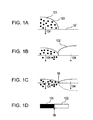
- Figs. 1A to 1C and 1E to 1H are schematic diagrams in chronological order showing permeation processes of black inks and yellow inks of Examples 1 to 4 on a recording medium; and Figs. 1D and 1I are diagrams showing boundary portions between the black ink and the yellow ink in Examples 1 to 4 as viewed from above the recording medium.
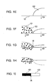
- Figs. 2A to 2C are diagrams each showing the arrangement of a color chip and a black chip in an ink jet recording head used in embodiments.
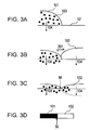
- Figs. 3A to 3C and 3E to 3H are schematic diagrams in chronological order showing a permeation process of a black ink and a yellow ink of Comparative Example 1 on a recording medium; and Figs. 3D and 3I are diagrams showing boundary portions between the black ink and the yellow ink of Comparative Example 1 as viewed from above the recording medium.
- Fig. 4 is a diagram showing a print pattern used in experiments for evaluating bleeding and undertrapping.
- Figs. 5A to 5C are diagrams showing how ink droplets are applied according to a related ink jet recording method.
- An ink set includes a black ink and a plurality of color inks.
- This ink set effectively prevents color bleeding between an ink of a color having the lowest brightness and an ink of a color having the highest brightness, feathering, and the like.
- the type or number of inks constituting the ink set is not particularly limited.
- the ink set may include a yellow ink, a cyan ink, a magenta ink, and a black ink.
- the ink with the lowest brightness is the black ink.
- the color having the highest brightness is the yellow ink and the color having the lowest brightness is the cyan ink.
- the viscosity of the black ink in the ink set of this embodiment is 1 cp (mPa ⁇ s) or more and 10 cp (mPa ⁇ s) or less and can be 1.5 cp (mPa ⁇ s) or more and 5 cp (mPa ⁇ s) or less.
- the black ink can be stably ejected from the ink jet nozzles at a high frequency.
- the surface tension of the black ink is 35 dyn/cm (mN/m) or more, can be 38 dyn/cm (mN/m) or more, and particularly can be 39 dyn/cm (mN/m) or more to obtain high-quality images.
- the surface tension of the black ink can be 40 dyn/cm (mN/m) or less.
- the viscosity of the color inks constituting the ink set of this embodiment can be 1 cp (mPa ⁇ s) or more and, in particular, can be 1.5 cp (mPa ⁇ s) or more.
- the viscosity of the color inks can be 10 cp (mPa ⁇ s) or less and, in particular, can be 5 cp (mPa ⁇ s) or less.
- the surface tension of the color ink can be 40 dyn/cm (mN/m) or less.
- the surface tension of the color ink may be 28 dyn/cm (mN/m) or more.
- the present inventors have found that because the yellow ink has a high brightness, the image uniformity obtained when using primary or secondary colors does not degrade even when the surface tension of the yellow ink is increased to a level comparable to that of the black ink.
- the surface tension of the cyan and magenta inks having lower brightness than the yellow ink can be 38 dyn/cm (mN/m) or less to achieve high image uniformity.
- one droplet of the ejected black ink can weigh 30 ng or less and one droplet of the ejected color ink can weigh 15 ng or less.
- two ink droplets unite with each other and the ink may overflow from the pixels, thereby degrading the sharpness of the image.
- the amount of one ink droplet is excessively large, the time taken for the ink droplet to dry tends to be long, and image quality is likely to be low.
- the difference in surface tension between the black ink and color ink significantly differing in brightness can be controlled to be 2 dyn/cm (mN/m) or less.
- the present inventors have found that when the surface tension of the black ink is substantially the same as the surface tension of the color ink, the occurrence of undertrapping and bleeding can be effectively suppressed.
- the surface tension of the black ink which has the lowest brightness
- the difference in surface tension between these inks is adjusted to be 2 dyn/cm (mN/m) or less
- particularly favorable effects can be obtained.
- the density of the black ink increases, thereby increasing sharpness, and undertrapping and color bleeding between the black ink and the color ink can be suppressed.
- bleeding between color inks can also be suppressed.
- the combination of the black ink and the color ink should satisfy the following conditions.
- a pigment ink containing a pigment as a coloring material should be used as the black ink.
- the surface tension of the color ink used in combination with the black ink and having the highest brightness among the color inks should be higher than the surface tension of other color inks.
- the difference in surface tension between the black ink and the color ink should be 2 dyn/cm (mN/m) or less.
- a pigment rather than a dye is used as the coloring material of the black ink due to the following reasons.
- Image forming with dye inks involves permeation of dyes into the interior of the recording medium such that the recording medium itself is colored. Accordingly, dyes rarely remain on the surface of the recording medium.
- pigment particles which are much larger than the particles of dyes, remain on the surface of the recording medium and the image is formed by the color of the pigment particles themselves on the surface. After pigment ink lands on the recording medium surface (such as a surface of a regular paper sheet) having a relatively high permeability, the solvent in the ink starts to evaporate.
- the dispersion becomes unstable and solid-liquid separation is accelerated, thereby producing aggregates of pigment particles.
- the black ink has a high surface tension and a low permeability as described above, the density of the pigment that stays on and is affixed onto the recording medium is high when the black ink alone is applied on the recording medium. Thus, an optical density higher than that achieved with a dye black ink can be obtained.
- An example of the pigment contained in the black ink is carbon black.
- the carbon black in the ink can be of a self-dispersive type.
- An example of a self dispersion carbon black is a carbon black having at least one hydrophilic group (anionic group or cationic group) serving as an ionic group bonded to the surface of the carbon black either directly or via another atomic group.
- a self dispersion carbon black achieves good dispersibility without the need to add a dispersant for dispersing the carbon black.
- aggregation of the ink ejected onto a recording medium can be easily controlled and bleeding can be easily suppressed. Thus, bleeding can be further suppressed when the self dispersion carbon black is used in the ink set.
- the hydrophilic group bonded to the surface may be -COO(M2), -SO 3 (M2), -PO 3 H(M2), - PO 3 (M2) 2 , or the like, where M2 represents a hydrogen atom, an alkali metal, ammonium, or organic ammonium.
- M2 represents a hydrogen atom, an alkali metal, ammonium, or organic ammonium.
- a self dispersion carbon black having -COO(M2) or -SO 3 (M2) bonded to the carbon black surface so that the carbon black is anionically charged has excellent dispersibility in the ink, and thus can be used in this embodiment.
- alkali metal represented by (M2) in the hydrophilic group include lithium, sodium, potassium, rubidium, and cesium.
- organic ammonium include monomethylammonium, dimethylammonium, trimethylammonium, ethylammonium, diethylammonium, triethylammonium, monomethanolammonium, dimethanolammonium, and trimethanolammonium.
- the ink containing a self dispersion carbon black containing ammonium or organic ammonium as (M2) can improve water resistance of recorded images. This is presumably because once the ink is applied on the recording medium, ammonium is decomposed and ammonia is evaporated.
- the following processes are available for producing a self dispersion carbon black containing ammonium as (M2). For example, there is a process of converting a self dispersion carbon black containing an alkali metal as (M2) by an ion exchange technique so that the (M2) is converted to ammonium. Alternatively, an acid may be added to produce an H-type, and then ammonium hydroxide may be added to convert (M2) to ammonium.
- An example of the process for producing an anionically charged self dispersion carbon black is a process involving oxidizing carbon black with sodium hypochlorite. A -COONa group can be chemically bonded on the carbon black surface by this process.
- the hydrophilic group bonded to the surface either directly or via another atomic group may be, for example, at least one quaternary ammonium group selected from the group consisting of: -SO 2 N + H 3 , -SO 2 N + H 2 COR, -N + H 3 , -N + R 3 ,
- R represents a linear or branched C1-C12 alkyl group, a substituted or unsubstituted phenyl group, or a substituted or unsubstituted naphthyl group.
- NO 3 - or CH 3 COO exists as the counter ion of the cationic group.
- the process for producing a cationically charged self dispersion carbon black including the hydrophilic group described above bonded on the surface is as follows. For example, in order to have an N-ethylpyridyl group represented by bonded on the surface, a method of treating the carbon black with 3-amino-N-ethylpyridinium bromide is used.
- a carbon black anionically or cationically charged by introduction of a hydrophilic group into the carbon black surface has excellent water dispersibility due to ionic repulsion.
- a carbon black maintains a stable dispersed state in an aqueous ink without the need to add a dispersant or the like.
- the hydrophilic groups described above may be bonded directly on the surface of the carbon black.
- another atomic group may be interposed between the carbon black surface and the hydrophilic group such that the hydrophilic group is indirectly bonded to the carbon black surface.
- Examples of the other atomic group include linear or branched C1-C12 alkylene groups, substituted or unsubstituted phenylene groups, and substituted or unsubstituted naphthylene groups.
- Examples of the substituents of the phenylene and naphthylene groups include linear or branched C1-C6 alkyl groups.
- Examples of the combination of the hydrophilic group and the atomic group include -C 2 H 4 COOM, -Ph-SO 3 M, -Ph-(COOM) m , and the like (where Ph represents a benzene ring and m represents 1 or 2).
- M represents a hydrogen atom, an alkali metal, ammonium, or organic ammonium as with (M2) described above.
- the self dispersion carbon black content in the ink can be 0.1 percent by mass or more or 1 percent by mass or more of the entire mass of the ink, and can be 15 percent by mass or less and particularly can be 10 percent by mass or less. When these conditions are satisfied, the self-dispersive carbon blacks can maintain a satisfactory dispersed state in the ink.
- a dye may also be added as a coloring material in addition to the self dispersion carbon blacks to adjust the color tone of the ink. Salt contained in the black ink
- At least one selected from (M1) 2 SO 4 , CH 3 COO(M1), Ph-(COO(M1)) n , (M1)NO 3 , (M1)Cl, (M1) Br, (M1) I, (M1) 2 SO 3 , and (M1) 2 CO 3 can be used as the salt contained in the black ink of this embodiment.
- M1 represents an alkali metal, ammonium, or organic ammonium
- Ph represents a benzene ring
- n represents 1 or 2.
- the salt content can be 0.05 percent by mass or more or 10.0 percent by mass or more with respect to the total mass of the ink. At a salt content below 0.05 percent by mass, images with high optical density may not always be obtained. At a salt content exceeding 10.0 percent by mass, storage stability of the ink and other properties may not be satisfactory.
- alkali metal examples include lithium, sodium, potassium, rubidium, and cesium.
- organic ammonium include monomethylammonium, dimethylammonium, trimethylammonium, monoethylammonium, diethylammonium, triethylammonium, monomethanolammonium, dimethanolammonium, trimethanolammonium, monoethanolammonium, diethanolammonium, and triethanolammonium. Solvent in black ink
- Examples of the ink solvent or dispersion medium in the black ink include water and mixtures of water and water-soluble organic solvents.
- Examples of the water-soluble organic solvents include C1-C4 alkyl alcohols such as methyl alcohol, ethyl alcohol, n-propyl alcohol, isopropyl alcohol, n-butyl alcohol, sec-butyl alcohol, and tert-butyl alcohol; amides such as dimethylformamide and dimethylacetamide; ketones and ketoalcohols such as acetone and diacetone alcohol; ethers such as tetrahydrofuran and dioxane; polyalkylene glycols such as polyethylene glycol and polypropylene glycol having an average molecular weight of about 200 to about 2,000; alkylene glycols having C2-C6 alkylene groups, such as ethylene glycol, propylene glycol, butylene glycol, triethylene glycol, 1,2,6-hexanetriol, thiodiglycol,
- the water-soluble organic solvent content in the ink is not particularly limited and can be in a range of 3 percent by mass to 50 percent by mass relative to the total mass of the ink.
- the water content in the ink can be in a range of 50 percent by mass to 95 percent by mass relative to the total mass of the ink.
- the viscosity and surface tension of the black ink may be adjusted to improve ejection property.
- the surface tension of the black ink can be improved by, for example, adding a surfactant. Any suitable surfactant may be used.
- surfactant examples include anionic surfactants such as ethylene oxide adducts of alcohols, ethylene oxide adducts of alkylphenols, ethylene oxide-propylene oxide copolymers, and ethylene oxide adducts of acetylene glycol.
- anionic surfactants such as ethylene oxide adducts of alcohols, ethylene oxide adducts of alkylphenols, ethylene oxide-propylene oxide copolymers, and ethylene oxide adducts of acetylene glycol.
- the ink may contain, in addition to the above-described components, a moisturizing solid component such as urea, a urea derivative, trimethylol propane, or trimethylol ethane.
- a moisturizing solid component such as urea, a urea derivative, trimethylol propane, or trimethylol ethane.
- the moisturizing solid component content in the ink can be 0.1 percent by mass or more and 20.0 percent by mass or less and in particular, can be 3.0 percent by mass or more and 10.0 percent by mass or less relative to the total mass of the ink. Coloring materials in color inks
- Common dyes and pigments may be used as the coloring materials in the color inks.
- the dyes include acidic dyes and direct dyes.
- an existing anionic dye or a novel anionic dye may be used. Any dye having appropriate color tone and density may be used. Two or more of such dyes may be used in combination.
- Specific examples of the anionic dyes are as follows.
- the coloring material content in the color ink used in this embodiment may be adequately adjusted so that the ink can be ejected properly during ink jet recording and so that the ink achieves the desired color tone and density.
- the coloring material content relative to the total mass of the ink can be 3 percent by mass or more and 50 percent by mass or less. Since the image density may become non-uniform depending on the order in which the inks are applied, the coloring material content can be 10 percent by mass or less relative to the total mass of the color ink including the coloring material.
- organic pigments examples include insoluble azo pigments such as toluidine red, toluidine maroon, hansa yellow, benzidine yellow, and pyrazolone red; soluble azo pigments such as Lytol red, Helio Bordeaux, pigment scarlet, and permanent red 2B; vat dye derivatives such as alizarin, indanthrone, and thioindigo maroon, and phthalocyanine pigments such as phthalocyanine blue and phthalocyanine green; quinacridone pigments such as quinacridone red and quinacridone magenta, perylene pigments such as perylene red and perylene scarlet, and isoindolinone pigments such as isoindolinone yellow and isoindolinone orange; imidazolone pigments such as benzimidazolone yellow, benzimidazolone orange, and benzimidazolone red, and pyranthrone pigments such as pyranthrone red and pyranthrone
- organic pigments are indicated by color index (C.I.) numbers as follows: C.I. Pigment Yellow 12, 13, 14, 17, 20, 24, 74, 83, 86, 93, 97, 109, 110, 117, 120, 125, 128, 137, 138, 147, 148, 150, 151, 153, 154, 166, 168, 180, and 185; C.I. Pigment Orange 16, 36, 43, 51, 55, 59, 61, and 71; C.I.
- pigments the following are favored: C.I. Pigment Yellow 74, 93, 97, 110, 120, 128, 138, 147, 148, 150, 151, 154, 180, and 185; C.I. Pigment Red 122; C.I. Pigment Violet 19; and C.I. Pigment Blue 15, 15:1, 15:3, and 15:4.
- Examples of the ink solvent or dispersion medium in the color ink include water and mixtures of water and water-soluble organic solvents.
- the same water-soluble organic solvents described above in the description of the black ink may be used as the water-soluble organic solvents.
- the water-soluble organic solvent content in the ink is not particularly limited and can be 3 percent by mass or more relative to the total mass of the ink.
- the water-soluble organic solvent in the ink can be 50 percent by mass or less.
- the water content in the ink can be 50 percent by mass or more relative to the total mass of the ink.
- the water content can be 95 percent by mass or less.
- the viscosity and surface tension of the ink may be adjusted so that the ink can be ejected properly.
- the surface tension of the color ink can be improved by, for example, adding a surfactant.
- Any suitable surfactant may be used.
- the surfactant include anionic surfactants such as ethylene oxide adducts of alcohols, ethylene oxide adducts of alkylphenols, ethylene oxide-propylene oxide copolymers, and ethylene oxide adducts of acetylene glycol.
- the color ink may contain, in addition to the above-described components, a moisturizing solid component such as urea, a urea derivative, trimethylol propane, or trimethylol ethane.
- a moisturizing solid component such as urea, a urea derivative, trimethylol propane, or trimethylol ethane.
- the moisturizing solid component content in the ink can be 0.1 percent by mass or more, in particular, can be 3.0 percent by mass or more.
- the moisturizing solid component content can be 20.0 percent by mass or less and in particular, can be 10.0 percent by mass or less relative to the total mass of the ink.
- Fig. 2A is a schematic diagram showing the arrangement of recording chips of a recording head mounted on a printer as viewed from the recording medium side.
- the recording head includes a substrate 1000 and a color ink chip 1100 and a black ink chip 1200 that are connected to the substrate 1000.
- the color ink chip 1100 includes a cyan ink ejection orifice row 22, a magenta ink ejection orifice row 23, and a yellow ink ejection orifice row 24 for ejecting color inks.
- the black ink chip 1200 includes an ejection orifice row 21 for ejecting a black ink.
- the black ink chip 1200 is longer than the color ink chip 1100 in the recording medium conveying direction (sub scanning direction). That is, the range of the black ink chip 1200 where the ejection orifices are aligned is longer than that of the color ink chip 1100. Moreover, the ejection orifice row 21 of the black ink chip 1200 is displaced from the orifice rows 22 to 24 of the color ink chip 1100 in the sub scanning direction by a predetermined distance.
- the black ink chip 1200 is longer than the color ink chip 1100 in the recording medium conveying direction (sub scanning direction), i.e., has a longer ejection orifice row. This is to improve the recording speed during recording of documents or the like using the black ink chip.
- the ejection orifice row of the black ink chip 1200 is long in the sub scanning direction, the length of the recording range in one scanning operation in the sub scanning direction becomes larger than that of the recording range of the color chip 1100.
- the color ink chip 1100 is displaced from the black ink chip 1200 in the recording medium conveying direction, as shown in Fig. 2A .
- each color ink ejection orifice row of the color ink chip 1100 is disposed such that its end at the downstream side in the conveying direction is located downstream of the downstream end of the ejection orifice row 21 of the black ink chip 1200 in the conveying direction.
- This structure creates a certain time difference between recording with the black ink ejected from the black ink chip 1200 and recording with the color inks ejected from the color ink chip 1100.
- the time difference can be 1 second or less.
- the recording head may be configured such that recording with color inks is performed before recording with the black ink.
- the time difference between the recordings can be 1 second or less.
- the printing method is called "1-scan delay printing."
- the recording head scans in a direction perpendicular to the recording medium conveying direction so as to increase the efficiency of printing.
- a recording head shown in Fig. 2C includes a color ink chip 1100 with color ink ejection orifice rows elongated in the recording medium conveying direction (sub scanning direction) so that a larger number of ejection orifices can be arranged in the color ink chip 1100 and the speed of color printing can be increased.
- the ejection orifice row 21 for ejecting the black ink is displaced from the position of the ejection orifice rows 22 to 24 of the color ink chip 1100 by a predetermined distance in the sub scanning direction.
- the overlap between the ejection orifice row 21 of the black ink chip 1200 and each of the ejection orifice rows 22, 23, and 24 of the color ink chip 1100 is larger than that in the recording head shown in Fig. 2A .
- a recording head in which the overlap between the ejection orifice row of the black ink and the ejection orifice rows of the color ink is large, as shown in Fig. 2C , more efficient recording is possible.
- recording is conducted by using the overlapping portion between the ejection orifice row of the black ink and the ejection orifice rows of the color ink, it is possible to simultaneously conduct recording with the black ink and recording with the color ink on the same recording region of the recording medium in one recording operation.
- the structure illustrated in Fig. 2C includes a large number of nozzles and can improve printing efficiency. According to this method, recording with a black ink and color inks is conducted on the same recording region of the recording medium in one scanning operation.
- the time difference between recording with the black ink ejected from the black ink chip 1200 and recording with the color inks from the color ink chip 1100 is extremely small.
- the order in which the black ink and the color inks are applied on the recording medium is reversed depending on the direction of scanning for recording.
- Such a printing method is called "zero-scan delay printing.”
- the recording head shown in Fig. 2C the recording head scans in a direction perpendicular to the recording medium conveying direction such that printing efficiency is improved.
- Each of the color inks was respectively prepared by mixing and dissolving the following components by thorough stirring and then pressure-filtrating the resultant solution through a micro filter (produced by FUJIFILM Corporation) having a pore size of 0.2 ⁇ m.
- Yellow pigment ink 4 Y4
- the surface tension ⁇ of each of the black and color inks prepared as described above was measured with a CBVP-series surface tensiometer A-1 (produced by Kyowa Interface Science Co., Ltd.).
- a measuring object i.e., an ink
- 5 ml to 6 ml of a measuring object, i.e., an ink was placed in a petri dish and measurement was conducted at a set temperature of 25 ⁇ 0.2°C.
- the types and observed surface tensions of the four inks constituting Ink set 1 were as follows
- Ink set 2 included four inks described below.
- Black ink 2 (Bk2), Yellow ink 2 (Y2), and Cyan ink 2 (C2) were prepared by changing the amount of Acetylenol EH in Black ink 1 (Bk1), Yellow ink 1 (Y1), and Cyan ink 1 (C1) prepared as described above, respectively, so that the surface tension of each ink was as follows:
- Ink set 3 included the following inks:
- Ink set 4 included the following inks:
- Ink set 5 included the following inks:
- Ink set 6 included the following inks:
- Ink set 7 included the following inks:
- Inks constituting Ink sets 1 to 7 are summarized in Table 1 below.
- Table 1 Inks Black Yellow Cyan Magenta Examples Ink set 1 Ink code BK1 Y1 C1 M1 Surface tension 40 40 36 36 coloring material Pigment Dye Dye Dye Ink set 2 Ink code BK2 Y2 C2 M2 Surface tension 39 37 34 36 Coloring material Pigment Dye Dye Dye Ink set 3 Ink code BK3 Y3 C3 M3 Surface tension 35 37 34 34 Coloring material Pigment Dye Dye Dye Ink set 4 Ink code BK4 Y4 C4 M4 Surface tension 35 33 30 30 Coloring material Pigment Pigment Pigment Pigment Pigment Pigment Comparative Examples Ink set 5 Ink code BK5 Y5 C5 M5 Surface tension 41 36 36 36 36 Coloring material Pigment Dye Dye Dye Ink set 6 Ink code BK6 Y6 C6 M6 Surface tension 36 39 34 36 Coloring material Pigment Dye Dye Dye Ink set 7 Ink code BK7 Y7 C
- Printing was conducted by 1-scan delay printing and zero-scan delay printing.
- an ink jet recording apparatus (trade name: Pixus 560i produced by Canon) modified to substantially apply 23 ng of black ink and 12 ng of a color ink in a 1/600 inch x 1/600 inch region was used.
- an ink jet recording apparatus (trade name: Pixus ip5200R produced by Canon) modified to substantially apply 23 ng of black ink and 12 ng of a color ink in a 1/600 inch x 1/600 inch region was used.
- a pattern as illustrated in Fig. 4 in which an image region in black was adjacent to an image region in color, was printed, and bleeding at the boundary portion and undertrapping in the black region were visually studied.
- the recording medium was PPC standard paper, Office Planner produced by Canon.
- the recording medium was PPC standard paper, Office Planner produced by Canon.
- Prints formed by 1-scan delay printing using Ink sets 1 to 4 are indicated as Examples 1 to 4, and prints formed by zero-scan delay printing using Ink sets 1 to 4 are indicated as Examples 5 to 8.
- Prints formed by 1-scan delay printing by using Ink sets 5 to 7 are indicated as Comparative Examples 1 to 3, and prints formed by zero-scan delay printing by using Ink sets 5 to 7 are indicated as Comparative Examples 4 to 6. Results of each of the above-described evaluations for each of the Examples and Comparative Examples are summarized in Tables 2-1 and 2-2.
- Table 2-1 Surface tension of Bk ink (mN/m) Difference in surface tension (1) B/w Bk ink and color ink (2) B/w color inks Ink set 1 40 0 4 Ink set 2 39 2 3 Ink set 3 35 -2 3 Ink set 4 35 2 3 Ink set 5 41 5 0 Ink set 6 36 -3 5 Ink set 7 39 -3 8 Note: (1): Surface tension of Bk ink - surface tension of a color ink (yellow ink) having highest brightness. (2) Surface tension of color ink (yellow ink) with highest brightness - surface tension of color ink with lowest surface tension.
- Examples 1 to 4 as shown in Table 2-2 indicate that prints formed by 1-scan delay printing by using Ink sets 1 to 4 were excellent in terms of suppressing ink bleeding, suppressing undertrapping, and achieving good print density.
- the print density of the black ink was particularly excellent.
- the same effects can be achieved with a recording head including the color ink chip 1100 and the black ink chip 1200 arranged as illustrated in Fig. 2B , in which printing with color inks was performed before printing with a black ink. With the arrangement of the chips shown in Fig. 2B , a certain time difference can be created between recording with color inks ejected from the color ink chip 1100 and recording with the black ink ejected from the black ink chip 1200.
- Examples 5 to 8 as shown in the table indicate that the prints formed by using Ink sets 1 to 4 by zero-scan delay printing (in which the time difference between printing with the black ink and printing with the color inks was very small) were excellent in terms of suppressing ink bleeding, suppressing undertrapping, and achieving good print density.
- Example 1 The ink permeation process of Example 1 in which the black ink was applied on the paper before the color inks in 1-scan delay printing will now be described with reference to Figs. 1A to 1D .
- the surface tension of Yellow ink 1 (Y1) with the highest brightness was higher than the surface tension of any other color inks.
- the difference in surface tension between Black ink 1 (Bk1) and Yellow ink 1 (Y1) was 2 dyn/cm (mN/m) or less.
- a black ink (Bk1) 101 having low permeability covered the recording medium 52 as shown in Fig. 1A .
- the black ink (Bk1) 101 contained pigment particles 103. Since the black ink (Bk1) 101 has low permeability, the black ink (Bk1) 101 permeated into the recording medium 52 slowly. Subsequently, an yellow ink (Y1) 102 having low permeability was applied ( Fig. 1B ). Since there was only a small difference in surface tension between the black ink (Bk1) 101 and the yellow ink (Y1) 102, there was substantially no ink movement at the interface between the black ink (Bk1) 101 and the yellow ink (Y1) 102. Thus, it can be assumed that the inks slowly permeated into the recording medium 52 ( Fig. 1C ).
- Fig. 1D is a diagram showing the boundary portion 56 between the black ink (Bk1) 101 and the yellow ink (Y1) 102 as viewed from above. Since physical properties of the black ink (Bk1) 101 were substantially the same as that of the yellow ink (Y1) 102, permeation was completed without having the inks, remaining as liquids on the recording medium surface, mixing with each other at the boundary portion 56. The present inventors have analyzed this state and found that it is important to strike a proper balance among the following factors: the permeation rate at which the black ink (Bk1) 101 and the yellow ink (Y1) 102 permeate into the recording medium 52 in a permeation direction 104, the amount of ink droplets, and the surface tension of the inks.
- Fig. 1E a yellow ink having high brightness was applied first; and then a black ink having low brightness was applied next, as shown in Fig. 1F . Since there was only a small difference in surface tension between the black ink (Bk1) 101 and the yellow ink (Y1) 102, it can be assumed that the inks slowly permeated into the recording medium 52 with little ink movement at the interface (see Figs. 1G and 1H).
- Fig. 1I is a diagram showing the boundary portion 56 at which the black ink (Bk1) 101 contacted the yellow ink (Y1) 102. Since the physical properties of the black ink (Bk1) 101 were substantially the same as those of the yellow ink (Y1) 102, permeation was completed without having the inks, remaining as liquids on the recording medium surface, mixing with each other at the boundary portion 56.
- Fig. 3D is a diagram of the boundary portion 56 between the black ink 101 and the yellow ink 102 viewed from above. Since the difference in physical properties between the black ink 101 and the yellow ink 102 was large, the inks remaining as liquids on the recording medium became mixed with each other at the boundary portion 56, thereby resulting in extensive bleeding. Bleeding at the boundary portion 56 was also extensive when the color ink was applied on the paper before the black ink. The ink permeation process will be described with reference to Figs. 3E to 3I .
- Fig. 3E an yellow ink having high brightness was applied; and then a black ink having low brightness was applied, as shown in Fig. 3F . Since the difference in surface tension between the black ink 101 and the yellow ink 102 was large, it can be assumed that permeation into the recording medium 52 occurred while the inks moved vigorously (indicated as 301 in the drawing) at the interface between the black ink and the yellow ink ( Figs. 3G and 3H).
- Fig. 3I is a diagram of the boundary portion 56 between the black ink 101 and the yellow ink 102 as viewed from above. Since the difference in physical properties between the black ink 101 and the yellow ink 102 was large, the inks remaining as liquids on the recording medium became mixed with each other at the boundary portion 56, thereby resulting in extensive bleeding.
- An ink set for ink jet recording includes a black ink (101) and a plurality of color inks of different colors.
- the black ink (101) contains a pigment (103) as a coloring material.
- the color ink (102) having the highest brightness among the plurality of color inks has the highest surface tension among the plurality of color inks.
- the difference in surface tension between the black ink (101) and the color ink (102) having the highest brightness is 2 dyn/cm (mN/m) or less.
Abstract
Description
- The present invention relates to an ink set for ink jet recording, the ink set including a black ink and a plurality of color inks, and to an ink jet recording method.
- One of the methods for recording characters and images known in the art is an ink jet recording method in which characters and images are formed on a recording medium with inks ejected onto the recording medium through nozzles of a recording head. In order to improve the print quality in the ink jet recording method, various techniques have been employed. One of such techniques is to use inks having permeability suitable for ink jet recording.
- For example, there is known an ink jet recording method in which inks that have a low permeation rate on recording paper, i.e., a recording medium, are used so that the amount of ink adhering on the surface and the nearby part of the surface of the recording medium is large, and so that the density and sharpness of the characters and drawings can be improved. An ink that has a low permeation rate and mostly remains on the surface of the recording medium is generally called "low-permeability ink," whereas an ink that has a high permeation rate is called "super-permeability ink."
- As illustrated in
Fig. 5A , in the cases where a super-permeability ink having high permeability is used, anink 51 permeates into the interior of arecording medium 52 immediately after theink 51 is ejected onto therecording medium 52, and the amount of theink 51 remaining on the surface is small. The rate of permeation of theink 51 into therecording medium 52 is high, and theink 51 may reach as far as the rear surface of therecording medium 52, depending on the permeability and other characteristics of the material of therecording medium 52. - An ink that quickly permeates into a recording medium as soon as the ink lands on the recording medium rarely mixes with other inks on the recording medium. Thus, such an ink is advantageous in that bleeding at the boundary regions of different colors can be suppressed. However, since the ink deeply permeates into the recording medium and diffuses over a wide range, coloring components of the dye or pigment become diffused. Moreover, since light that is incident on the recording medium is reflected at a deep position with respect to the surface of the recording medium, the density of the recorded image tends to be low. Furthermore, the
ink 51 may diffuse widely in all directions, resulting in an excessive increase in size of the recording dot, and whisker-like bleeding (feathering) may occur around the edge of the dot, resulting in an image with a blurred contour. - In contrast, as illustrated in
Fig. 5B , when a low-permeability ink 53 having low permeability is used, the low-permeability ink 53 remains protruding on the surface of therecording medium 52, and the components of the ink such as a solvent can easily evaporate under such a condition. Thus, the amount of low-permeability ink 53 permeating into therecording medium 52 in the thickness direction is small. - When the amount of ink remaining on the recording medium surface is large, the density of the image tends to be high. Moreover, since the amount of ink diffusing into the recording medium in one dot is significantly lower than in the case of a super-permeability ink, a low-permeability ink can record sharp images. However, the rate of permeation of this type of ink into the recording medium is low, and the time required for the ink on the recording medium surface to fix is long. Thus, when other inks are ejected onto nearby positions, flow-out of inks occurs between the inks. Thus, bleeding occurs in the boundary portion between different colors, and the image quality tends to be low.
- It has been a wide practice up to the present to use a poorly permeable ink as a black ink and highly permeable inks as inks of other colors. A black ink is usually used for recording letters and drawings, minute lines and points of which must be clearly drawn and which must be easily recognizable. Thus, a low-permeability ink that can achieve high recording density and can record sharp contours has been used as a black ink. In recording a color image in which dots of different colors are usually disposed next to one another, super-permeability inks that can record sharp boundaries and that can suppress bleeding in the boundary regions between different colors have been used.
- However, although different inks with different permeability have been used as a black ink and color inks to comply with different requirements for characteristics of images to be recorded, the following problems have occurred. As shown in
Fig. 5C , when ablack dot 54 of an ink having low permeability is adjacent to acolor dot 55 of an ink having high permeability, flow-out may occur between the adjacent dots, thereby degrading the recording quality. In theblack dot 54, the ink protruding from the recording medium surface flows out from aboundary portion 56 into thecolor dot 55, resulting in a decrease in density in theboundary portion 56 at the black dot side. As a result, the density of the contour of the black dot decreases, and a whitish blurred image is produced (undertrapping). In the color dot, the black ink mixes in theboundary portion 56, and the contour becomes unclear (bleeding). This case illustrates that when inks with different permeabilities are adjacent to each other, undertrapping or bleeding may occur in theboundary portion 56, and the quality of recording tends to be low. These phenomena are particularly frequent when recording of images is conducted at a high speed. - Many methods for preventing bleeding have been proposed. For example, Japanese Patent Laid-Open No.
60-197778 60-197778 - Japanese Patent Laid-Open No.
2000-198955 - Another available technique involves leaving the recording medium and the black ink ejected on the medium to stand for a time long enough to allow the ink, particularly a poorly permeable ink, to fix on the recording medium to an extent sufficient to prevent bleeding. However, according to this technique, a significantly large time difference must be provided between printing with the black ink and printing with the color inks. The technique thus has a low throughput and is not suitable for high-speed recording.
- Another proposed technique involves decreasing (reduction of) the amount of ink supplied in one scanning operation and repeating scanning at predetermined time intervals (multipass printing). However, in multipass printing, the number of times of scanning operations is increased and the printing time per sheet (throughput) can be very long if the scanning intervals are large. Another concern is that a fixing unit including a heater for forcibly evaporating the ink is sometimes used. If the fixing unit is to be included, the size of the apparatus increases, and there is also a disadvantage of uneconomical energy consumption.
- The present invention provides an ink set for ink jet recording that can create sharp images with suppressed undertrapping and bleeding at the boundaries between a color ink and a black ink even when the time difference between application of one ink and application of the other ink is small. An ink jet recording method that involves using such an ink set for ink jet recording is also provided.
- The present invention in its first aspect provides an ink set for ink jet recording as specified in claims 1 to 7.
- The present invention in its second aspect provides an ink jet recording method as specified in claims 8 to 12.
- Further features of the present invention will become apparent from the following description of exemplary embodiments with reference to the attached drawings.
-
Figs. 1A to 1C and1E to 1H are schematic diagrams in chronological order showing permeation processes of black inks and yellow inks of Examples 1 to 4 on a recording medium; andFigs. 1D and1I are diagrams showing boundary portions between the black ink and the yellow ink in Examples 1 to 4 as viewed from above the recording medium. -
Figs. 2A to 2C are diagrams each showing the arrangement of a color chip and a black chip in an ink jet recording head used in embodiments. -
Figs. 3A to 3C and3E to 3H are schematic diagrams in chronological order showing a permeation process of a black ink and a yellow ink of Comparative Example 1 on a recording medium; andFigs. 3D and3I are diagrams showing boundary portions between the black ink and the yellow ink of Comparative Example 1 as viewed from above the recording medium. -
Fig. 4 is a diagram showing a print pattern used in experiments for evaluating bleeding and undertrapping. -
Figs. 5A to 5C are diagrams showing how ink droplets are applied according to a related ink jet recording method. - The present invention will now be described in detail below by way of embodiments. An ink set according to an embodiment includes a black ink and a plurality of color inks. This ink set effectively prevents color bleeding between an ink of a color having the lowest brightness and an ink of a color having the highest brightness, feathering, and the like. The type or number of inks constituting the ink set is not particularly limited. For example, the ink set may include a yellow ink, a cyan ink, a magenta ink, and a black ink.
- Given a set of inks in a typical ink set, bleeding at the boundaries is most noticeable between the ink of a color having the highest brightness and the ink of a color having the lowest brightness among inks contained in the ink set. Furthermore, the color bleeding that occurs at the boundary of these two colors is highly distinctive. This distinctive and noticeable color bleeding can be effectively prevented according to the first embodiment of the present invention.
- Typically, in a full color ink set containing yellow, cyan, magenta, and black inks, the ink with the lowest brightness is the black ink. In an ink set including three colors, namely, yellow, cyan, and magenta, the color having the highest brightness is the yellow ink and the color having the lowest brightness is the cyan ink.
- The viscosity of the black ink in the ink set of this embodiment is 1 cp (mPa·s) or more and 10 cp (mPa·s) or less and can be 1.5 cp (mPa·s) or more and 5 cp (mPa·s) or less. When this condition is satisfied, the black ink can be stably ejected from the ink jet nozzles at a high frequency. The surface tension of the black ink is 35 dyn/cm (mN/m) or more, can be 38 dyn/cm (mN/m) or more, and particularly can be 39 dyn/cm (mN/m) or more to obtain high-quality images. The surface tension of the black ink can be 40 dyn/cm (mN/m) or less.
- The viscosity of the color inks constituting the ink set of this embodiment can be 1 cp (mPa·s) or more and, in particular, can be 1.5 cp (mPa·s) or more. The viscosity of the color inks can be 10 cp (mPa·s) or less and, in particular, can be 5 cp (mPa·s) or less. When these conditions are satisfied, the color inks can be stably ejected from the ink jet nozzles at a high frequency. Occurrence of bleeding in the boundary regions between adjacent different color images degrades the quality of the multicolor image. Thus, the surface tension of the color ink can be 40 dyn/cm (mN/m) or less. To improve ejection property of the ink, the surface tension of the color ink may be 28 dyn/cm (mN/m) or more.
- As described above, increasing the surface tension of the black ink enhances the quality of printed characters. However, to improve the image uniformity obtained when using primary and secondary colors, it is effective to decrease the surface tension of the color inks. The present inventors have found that because the yellow ink has a high brightness, the image uniformity obtained when using primary or secondary colors does not degrade even when the surface tension of the yellow ink is increased to a level comparable to that of the black ink. The surface tension of the cyan and magenta inks having lower brightness than the yellow ink can be 38 dyn/cm (mN/m) or less to achieve high image uniformity.
- In recording images or the like by using the ink set of this embodiment, one droplet of the ejected black ink can weigh 30 ng or less and one droplet of the ejected color ink can weigh 15 ng or less. When adjacent pixels are printed during high-speed printing using inks having high surface tensions, two ink droplets unite with each other and the ink may overflow from the pixels, thereby degrading the sharpness of the image. When the amount of one ink droplet is excessively large, the time taken for the ink droplet to dry tends to be long, and image quality is likely to be low. However, when the amount of each ink droplet ejected is controlled to be within the above-described ranges during recording, inks dry quickly and a high-density, high-quality image can be obtained. Thus, the above-described conditions should be satisfied.
- In this embodiment, the difference in surface tension between the black ink and color ink significantly differing in brightness can be controlled to be 2 dyn/cm (mN/m) or less. The present inventors have found that when the surface tension of the black ink is substantially the same as the surface tension of the color ink, the occurrence of undertrapping and bleeding can be effectively suppressed. When the surface tension of the black ink, which has the lowest brightness, is controlled to be higher than the surface tension of the color ink having the highest brightness and the difference in surface tension between these inks is adjusted to be 2 dyn/cm (mN/m) or less, particularly favorable effects can be obtained. In other words, the density of the black ink increases, thereby increasing sharpness, and undertrapping and color bleeding between the black ink and the color ink can be suppressed. Furthermore, bleeding between color inks can also be suppressed.
- Thus, in this embodiment, the combination of the black ink and the color ink should satisfy the following conditions. First, a pigment ink containing a pigment as a coloring material should be used as the black ink. Second, the surface tension of the color ink used in combination with the black ink and having the highest brightness among the color inks should be higher than the surface tension of other color inks. Third, the difference in surface tension between the black ink and the color ink should be 2 dyn/cm (mN/m) or less.
- A pigment rather than a dye is used as the coloring material of the black ink due to the following reasons. Image forming with dye inks involves permeation of dyes into the interior of the recording medium such that the recording medium itself is colored. Accordingly, dyes rarely remain on the surface of the recording medium. In contrast, in image forming with pigment inks, pigment particles, which are much larger than the particles of dyes, remain on the surface of the recording medium and the image is formed by the color of the pigment particles themselves on the surface. After pigment ink lands on the recording medium surface (such as a surface of a regular paper sheet) having a relatively high permeability, the solvent in the ink starts to evaporate. During evaporation, the dispersion becomes unstable and solid-liquid separation is accelerated, thereby producing aggregates of pigment particles. Since the black ink has a high surface tension and a low permeability as described above, the density of the pigment that stays on and is affixed onto the recording medium is high when the black ink alone is applied on the recording medium. Thus, an optical density higher than that achieved with a dye black ink can be obtained. Once the black ink and the color ink are ejected on the recording medium, solid-liquid separation is accelerated and pigment particles form aggregates, thereby preventing the color ink from penetrating into the black ink. Moreover, when the surface tension of the color ink is substantially the same as the surface tension of the black ink, inks on the recording medium move very little. Thus, penetrations of the color ink into the black ink are effectively suppressed. The above-described findings were made in studies conducted by the present inventors.
- An example of the pigment contained in the black ink is carbon black. The carbon black in the ink can be of a self-dispersive type. An example of a self dispersion carbon black is a carbon black having at least one hydrophilic group (anionic group or cationic group) serving as an ionic group bonded to the surface of the carbon black either directly or via another atomic group. A self dispersion carbon black achieves good dispersibility without the need to add a dispersant for dispersing the carbon black. Furthermore, by using a self dispersion carbon black in an ink, aggregation of the ink ejected onto a recording medium can be easily controlled and bleeding can be easily suppressed. Thus, bleeding can be further suppressed when the self dispersion carbon black is used in the ink set.
- In the cases in which a carbon black having an anionic group bonded to the surface either directly or via another atomic group is used, the hydrophilic group bonded to the surface may be -COO(M2), -SO3(M2), -PO3H(M2), - PO3(M2)2, or the like, where M2 represents a hydrogen atom, an alkali metal, ammonium, or organic ammonium. Among the carbon blacks of this type, a self dispersion carbon black having -COO(M2) or -SO3(M2) bonded to the carbon black surface so that the carbon black is anionically charged has excellent dispersibility in the ink, and thus can be used in this embodiment.
- Specific examples of the alkali metal represented by (M2) in the hydrophilic group include lithium, sodium, potassium, rubidium, and cesium. Specific examples of the organic ammonium include monomethylammonium, dimethylammonium, trimethylammonium, ethylammonium, diethylammonium, triethylammonium, monomethanolammonium, dimethanolammonium, and trimethanolammonium.
- The ink containing a self dispersion carbon black containing ammonium or organic ammonium as (M2) can improve water resistance of recorded images. This is presumably because once the ink is applied on the recording medium, ammonium is decomposed and ammonia is evaporated. The following processes are available for producing a self dispersion carbon black containing ammonium as (M2). For example, there is a process of converting a self dispersion carbon black containing an alkali metal as (M2) by an ion exchange technique so that the (M2) is converted to ammonium. Alternatively, an acid may be added to produce an H-type, and then ammonium hydroxide may be added to convert (M2) to ammonium. An example of the process for producing an anionically charged self dispersion carbon black is a process involving oxidizing carbon black with sodium hypochlorite. A -COONa group can be chemically bonded on the carbon black surface by this process.
- As for cationically charged carbon blacks, the hydrophilic group bonded to the surface either directly or via another atomic group may be, for example, at least one quaternary ammonium group selected from the group consisting of:
-SO2N+H3, -SO2N+H2COR, -N+H3 , -N+R3,


- In the formulate above, R represents a linear or branched C1-C12 alkyl group, a substituted or unsubstituted phenyl group, or a substituted or unsubstituted naphthyl group. Of note is that NO3 - or CH3COO, for example, exists as the counter ion of the cationic group. The process for producing a cationically charged self dispersion carbon black including the hydrophilic group described above bonded on the surface is as follows. For example, in order to have an N-ethylpyridyl group represented by

- A carbon black anionically or cationically charged by introduction of a hydrophilic group into the carbon black surface has excellent water dispersibility due to ionic repulsion. Thus, such a carbon black maintains a stable dispersed state in an aqueous ink without the need to add a dispersant or the like. The hydrophilic groups described above may be bonded directly on the surface of the carbon black. Alternatively, another atomic group may be interposed between the carbon black surface and the hydrophilic group such that the hydrophilic group is indirectly bonded to the carbon black surface.
- Examples of the other atomic group include linear or branched C1-C12 alkylene groups, substituted or unsubstituted phenylene groups, and substituted or unsubstituted naphthylene groups. Examples of the substituents of the phenylene and naphthylene groups include linear or branched C1-C6 alkyl groups. Examples of the combination of the hydrophilic group and the atomic group include -C2H4COOM, -Ph-SO3M, -Ph-(COOM)m, and the like (where Ph represents a benzene ring and m represents 1 or 2). In these formulas, M represents a hydrogen atom, an alkali metal, ammonium, or organic ammonium as with (M2) described above.
- Two or more types of self dispersion carbon blacks described above may be adequately selected for use as coloring materials for the ink. The self dispersion carbon black content in the ink can be 0.1 percent by mass or more or 1 percent by mass or more of the entire mass of the ink, and can be 15 percent by mass or less and particularly can be 10 percent by mass or less. When these conditions are satisfied, the self-dispersive carbon blacks can maintain a satisfactory dispersed state in the ink. A dye may also be added as a coloring material in addition to the self dispersion carbon blacks to adjust the color tone of the ink. Salt contained in the black ink
- At least one selected from (M1)2SO4, CH3COO(M1), Ph-(COO(M1))n, (M1)NO3, (M1)Cl, (M1) Br, (M1) I, (M1)2SO3, and (M1)2CO3 can be used as the salt contained in the black ink of this embodiment. Here, M1 represents an alkali metal, ammonium, or organic ammonium, Ph represents a benzene ring, and n represents 1 or 2. The salt content can be 0.05 percent by mass or more or 10.0 percent by mass or more with respect to the total mass of the ink. At a salt content below 0.05 percent by mass, images with high optical density may not always be obtained. At a salt content exceeding 10.0 percent by mass, storage stability of the ink and other properties may not be satisfactory.
- Specific examples of the alkali metal include lithium, sodium, potassium, rubidium, and cesium. Specific examples of the organic ammonium include monomethylammonium, dimethylammonium, trimethylammonium, monoethylammonium, diethylammonium, triethylammonium, monomethanolammonium, dimethanolammonium, trimethanolammonium, monoethanolammonium, diethanolammonium, and triethanolammonium. Solvent in black ink
- Examples of the ink solvent or dispersion medium in the black ink include water and mixtures of water and water-soluble organic solvents. Examples of the water-soluble organic solvents include C1-C4 alkyl alcohols such as methyl alcohol, ethyl alcohol, n-propyl alcohol, isopropyl alcohol, n-butyl alcohol, sec-butyl alcohol, and tert-butyl alcohol; amides such as dimethylformamide and dimethylacetamide; ketones and ketoalcohols such as acetone and diacetone alcohol; ethers such as tetrahydrofuran and dioxane; polyalkylene glycols such as polyethylene glycol and polypropylene glycol having an average molecular weight of about 200 to about 2,000; alkylene glycols having C2-C6 alkylene groups, such as ethylene glycol, propylene glycol, butylene glycol, triethylene glycol, 1,2,6-hexanetriol, thiodiglycol, hexylene glycol, and diethylene glycol; alkyl ether acetates such as polyethylene glycol monomethyl ether acetate; glycerol; alkyl ethers of polyalcohols such as ethylene glycol monomethyl(or ethyl) ether, diethylene glycol methyl(or ethyl) ether, and triethylene glycol monomethyl(or ethyl) ether; and N-methyl-2-pyrrolidone, 2-pyrrolidone, and 1,3-dimethyl-2-imidazolidinone.
- The water-soluble organic solvent content in the ink is not particularly limited and can be in a range of 3 percent by mass to 50 percent by mass relative to the total mass of the ink. The water content in the ink can be in a range of 50 percent by mass to 95 percent by mass relative to the total mass of the ink. The viscosity and surface tension of the black ink may be adjusted to improve ejection property. The surface tension of the black ink can be improved by, for example, adding a surfactant. Any suitable surfactant may be used. Examples of the surfactant include anionic surfactants such as ethylene oxide adducts of alcohols, ethylene oxide adducts of alkylphenols, ethylene oxide-propylene oxide copolymers, and ethylene oxide adducts of acetylene glycol.
- The ink may contain, in addition to the above-described components, a moisturizing solid component such as urea, a urea derivative, trimethylol propane, or trimethylol ethane. The moisturizing solid component content in the ink can be 0.1 percent by mass or more and 20.0 percent by mass or less and in particular, can be 3.0 percent by mass or more and 10.0 percent by mass or less relative to the total mass of the ink. Coloring materials in color inks
- Common dyes and pigments may be used as the coloring materials in the color inks. Examples of the dyes include acidic dyes and direct dyes. For example, an existing anionic dye or a novel anionic dye may be used. Any dye having appropriate color tone and density may be used. Two or more of such dyes may be used in combination. Specific examples of the anionic dyes are as follows.
- C.I. Direct Yellow 8, 11, 12, 27, 28, 33, 39, 44, 50, 58, 85, 86, 87, 88, 89, 98, 100, 110, and 132; C.I.
Acid Yellow 1, 3, 7, 11, 17, 23, 25, 29, 36, 38, 40, 42, 44, 76, 98, and 99; C.I. Reactive Yellow 2, 3, 17, 25, 37, and 42; and C.I. Food Yellow 3 - C.I.
Direct Red Acid Red Reactive Red - C.I.
Direct Blue 1, 15, 22, 25, 41, 76, 77, 80, 86, 90, 98, 106, 108, 120, 158, 163, 168, 199, and 226; C.I.Acid Blue Reactive Blue 4, 5, 7, 13, 14, 15, 18, 19, 21, 26, 27, 29, 32, 38, 40, 44, and 100 - C.I.
Direct Black Acid Black - The coloring material content in the color ink used in this embodiment may be adequately adjusted so that the ink can be ejected properly during ink jet recording and so that the ink achieves the desired color tone and density. For example, the coloring material content relative to the total mass of the ink can be 3 percent by mass or more and 50 percent by mass or less. Since the image density may become non-uniform depending on the order in which the inks are applied, the coloring material content can be 10 percent by mass or less relative to the total mass of the color ink including the coloring material.
- Examples of the organic pigments include insoluble azo pigments such as toluidine red, toluidine maroon, hansa yellow, benzidine yellow, and pyrazolone red; soluble azo pigments such as Lytol red, Helio Bordeaux, pigment scarlet, and permanent red 2B; vat dye derivatives such as alizarin, indanthrone, and thioindigo maroon, and phthalocyanine pigments such as phthalocyanine blue and phthalocyanine green; quinacridone pigments such as quinacridone red and quinacridone magenta, perylene pigments such as perylene red and perylene scarlet, and isoindolinone pigments such as isoindolinone yellow and isoindolinone orange; imidazolone pigments such as benzimidazolone yellow, benzimidazolone orange, and benzimidazolone red, and pyranthrone pigments such as pyranthrone red and pyranthrone orange; thioindigo pigments, condensed azo pigments, diketopyrrolopyrrole pigments, flavanthrone yellow, acylamido yellow, quinophthalone yellow, nickel azo yellow, copper azomethine yellow, and perinone orange; and anthrone orange, dianthraquinonyl red, and dioxazine violet.
- Examples of the organic pigments are indicated by color index (C.I.) numbers as follows: C.I. Pigment Yellow 12, 13, 14, 17, 20, 24, 74, 83, 86, 93, 97, 109, 110, 117, 120, 125, 128, 137, 138, 147, 148, 150, 151, 153, 154, 166, 168, 180, and 185; C.I.
Pigment Orange Pigment Red Pigment Violet 19, 23, 29, 30, 37, 40, and 50; C.I. Pigment Blue 15, 15:1, 15:3, 15:4, 15:6, 22, 60, and 64; C.I. Pigment Green 7 and 36; and C.I.Pigment Brown 23, 25, and 26. - Of these pigments, the following are favored: C.I. Pigment Yellow 74, 93, 97, 110, 120, 128, 138, 147, 148, 150, 151, 154, 180, and 185; C.I. Pigment Red 122; C.I. Pigment Violet 19; and C.I. Pigment Blue 15, 15:1, 15:3, and 15:4.
- Examples of the ink solvent or dispersion medium in the color ink include water and mixtures of water and water-soluble organic solvents. The same water-soluble organic solvents described above in the description of the black ink may be used as the water-soluble organic solvents. The water-soluble organic solvent content in the ink is not particularly limited and can be 3 percent by mass or more relative to the total mass of the ink. The water-soluble organic solvent in the ink can be 50 percent by mass or less. The water content in the ink can be 50 percent by mass or more relative to the total mass of the ink. The water content can be 95 percent by mass or less. In order to apply the color ink on a recording medium by an ink jet technique (e.g., bubble jet (registered trade name)), the viscosity and surface tension of the ink may be adjusted so that the ink can be ejected properly. The surface tension of the color ink can be improved by, for example, adding a surfactant. Any suitable surfactant may be used. Examples of the surfactant include anionic surfactants such as ethylene oxide adducts of alcohols, ethylene oxide adducts of alkylphenols, ethylene oxide-propylene oxide copolymers, and ethylene oxide adducts of acetylene glycol.
- As with the black ink, the color ink may contain, in addition to the above-described components, a moisturizing solid component such as urea, a urea derivative, trimethylol propane, or trimethylol ethane.
The moisturizing solid component content in the ink can be 0.1 percent by mass or more, in particular, can be 3.0 percent by mass or more. The moisturizing solid component content can be 20.0 percent by mass or less and in particular, can be 10.0 percent by mass or less relative to the total mass of the ink. - A structure of a recording head and a printing method of this embodiment will now be described with reference to
Figs. 2A to 2C . -
Fig. 2A is a schematic diagram showing the arrangement of recording chips of a recording head mounted on a printer as viewed from the recording medium side. As shown in the drawing, the recording head includes asubstrate 1000 and acolor ink chip 1100 and ablack ink chip 1200 that are connected to thesubstrate 1000. Thecolor ink chip 1100 includes a cyan inkejection orifice row 22, a magenta inkejection orifice row 23, and a yellow inkejection orifice row 24 for ejecting color inks. Theblack ink chip 1200 includes anejection orifice row 21 for ejecting a black ink. Theblack ink chip 1200 is longer than thecolor ink chip 1100 in the recording medium conveying direction (sub scanning direction). That is, the range of theblack ink chip 1200 where the ejection orifices are aligned is longer than that of thecolor ink chip 1100. Moreover, theejection orifice row 21 of theblack ink chip 1200 is displaced from theorifice rows 22 to 24 of thecolor ink chip 1100 in the sub scanning direction by a predetermined distance. - As shown in
Fig. 2A , theblack ink chip 1200 is longer than thecolor ink chip 1100 in the recording medium conveying direction (sub scanning direction), i.e., has a longer ejection orifice row. This is to improve the recording speed during recording of documents or the like using the black ink chip. When the ejection orifice row of theblack ink chip 1200 is long in the sub scanning direction, the length of the recording range in one scanning operation in the sub scanning direction becomes larger than that of the recording range of thecolor chip 1100. - In order to conduct recording with the black ink before the color inks are applied onto the same recording region of the recording medium, the
color ink chip 1100 is displaced from theblack ink chip 1200 in the recording medium conveying direction, as shown inFig. 2A . In particular, each color ink ejection orifice row of thecolor ink chip 1100 is disposed such that its end at the downstream side in the conveying direction is located downstream of the downstream end of theejection orifice row 21 of theblack ink chip 1200 in the conveying direction. This structure creates a certain time difference between recording with the black ink ejected from theblack ink chip 1200 and recording with the color inks ejected from thecolor ink chip 1100. The time difference can be 1 second or less. (If a large time difference is set in order to allow the black ink to sufficiently permeate into the recording medium, the throughput decreases and high-speed recording is no longer possible.) Alternatively, as shown inFig. 2B , the recording head may be configured such that recording with color inks is performed before recording with the black ink. In such a case as well, the time difference between the recordings can be 1 second or less. - When the time difference is equal to the length of time required for one scan operation of the recording head, the printing method is called "1-scan delay printing." In the case in which the recording head shown in
Fig. 2A is used, the recording head scans in a direction perpendicular to the recording medium conveying direction so as to increase the efficiency of printing. - In contrast, a recording head shown in
Fig. 2C includes acolor ink chip 1100 with color ink ejection orifice rows elongated in the recording medium conveying direction (sub scanning direction) so that a larger number of ejection orifices can be arranged in thecolor ink chip 1100 and the speed of color printing can be increased. Theejection orifice row 21 for ejecting the black ink is displaced from the position of theejection orifice rows 22 to 24 of thecolor ink chip 1100 by a predetermined distance in the sub scanning direction. The overlap between theejection orifice row 21 of theblack ink chip 1200 and each of theejection orifice rows color ink chip 1100 is larger than that in the recording head shown inFig. 2A . - With a recording head in which the overlap between the ejection orifice row of the black ink and the ejection orifice rows of the color ink is large, as shown in
Fig. 2C , more efficient recording is possible. In the case in which recording is conducted by using the overlapping portion between the ejection orifice row of the black ink and the ejection orifice rows of the color ink, it is possible to simultaneously conduct recording with the black ink and recording with the color ink on the same recording region of the recording medium in one recording operation. The structure illustrated inFig. 2C includes a large number of nozzles and can improve printing efficiency. According to this method, recording with a black ink and color inks is conducted on the same recording region of the recording medium in one scanning operation. Thus, the time difference between recording with the black ink ejected from theblack ink chip 1200 and recording with the color inks from thecolor ink chip 1100 is extremely small. Moreover, the order in which the black ink and the color inks are applied on the recording medium is reversed depending on the direction of scanning for recording. Such a printing method is called "zero-scan delay printing." In the case in which the recording head shown inFig. 2C is used, the recording head scans in a direction perpendicular to the recording medium conveying direction such that printing efficiency is improved. - Examples and Comparative Examples, which will now be described, should not be read as limiting the scope of the present invention. In the following description, "part" or "%" is on a mass basis unless otherwise noted. The total of the components in an ink is 100 parts. Acetylenol EH (trade name, produced by Kawaken Fine Chemicals, Co., Ltd.) in the composition is an acetylene glycol-ethylene oxide adduct.
-
- · Black self-dispersion pigment dispersion (trade name: CABOJET 300 produced by Cabot Corporation) 50 parts
- · Ammonium sulfate 1 part
- · Trimethylolpropane 5 parts
- · Glycerol 5 parts
- · 2-Pyrrolidone 5 parts
- · Acetylenol EH 0.24 parts
- · Water Balance
- Each of the color inks was respectively prepared by mixing and dissolving the following components by thorough stirring and then pressure-filtrating the resultant solution through a micro filter (produced by FUJIFILM Corporation) having a pore size of 0.2 µm.
-
- · Acetylenol EH 0.2 parts
- · Trimethylolpropane 5 parts
- · Glycerol 5 parts
- · 2-Pyrrolidone 5 parts
- · C.I. Direct Yellow 86 5 parts
- · Water Balance
-
- · Acetylenol EH 0.5 parts
- · Trimethylolpropane 5 parts
- · Glycerol 5 parts
- · 2-Pyrrolidone 5 parts
- · C.I. Acid Red 289 5 parts
- · Water Balance
-
- · Acetylenol EH 0.3 parts
- · Trimethylolpropane 5 parts
- · Glycerol 5 parts
- · 2-Pyrrolidone 5 parts
- · C.I. Acid Blue 9 5 parts
- · Water Balance
-
- · Yellow self-dispersion pigment dispersion (trade name: CABOJET 270 produced by Cabot Corporation) 50 parts
- · Trimethylolpropane 5 parts
- · Glycerol 5 parts
- · 2-Pyrrolidone 5 parts
- · Acetylenol EH 0.8 parts
- · Water Balance
-
- · Cyan self-dispersion pigment dispersion (trade name: CABOJET 250 produced by Cabot Corporation) 50 parts
- · Trimethylolpropane 5 parts
- · Glycerol 5 parts
- · 2-Pyrrolidone 5 parts
- · Acetylenol EH 1 part
- · Water Balance
-
- · Magenta self-dispersion pigment dispersion (trade name: CABOJET 260 produced by Cabot Corporation) 50 parts
- · Trimethylolpropane 5 parts
- · Glycerol 5 parts
- · 2-Pyrrolidone 5 parts
- · Acetylenol EH 1.2 parts
- · Water Balance
- The surface tension γ of each of the black and color inks prepared as described above was measured with a CBVP-series surface tensiometer A-1 (produced by Kyowa Interface Science Co., Ltd.). In particular, 5 ml to 6 ml of a measuring object, i.e., an ink, was placed in a petri dish and measurement was conducted at a set temperature of 25 ±0.2°C. The types and observed surface tensions of the four inks constituting Ink set 1 were as follows
- Black ink 1 (Bk1) : 40 dyn/cm (mN/m)
- Yellow ink 1 (Y1) : 40 dyn/cm (mN/m)
- Cyan ink 1 (C1): 36 dyn/cm (mN/m)
- Magenta ink (M1): 36 dyn/cm (mN/m)
- Ink set 2 included four inks described below. Black ink 2 (Bk2), Yellow ink 2 (Y2), and Cyan ink 2 (C2) were prepared by changing the amount of Acetylenol EH in Black ink 1 (Bk1), Yellow ink 1 (Y1), and Cyan ink 1 (C1) prepared as described above, respectively, so that the surface tension of each ink was as follows:
- Black ink 2 (Bk2): 39 dyn/cm (mN/m)
- Yellow ink 2 (Y2): 37 dyn/cm (mN/m)
- Cyan ink 2 (C2): 34 dyn/cm (mN/m)
- Magenta ink 2 (M2): The same as Magenta ink 1 (M1) in Ink set 1
- Ink set 3 included the following inks:
- Black ink 3 (Bk3): 35 dyn/cm (mN/m)
- Yellow ink 3 (Y3): The same as Yellow ink 2 (Y2) in Ink set 2
- Cyan ink 3 (C3): The same as Cyan ink 2 (C2) in Ink set 2 Magenta ink 3 (M3): 34 dyn/cm (mN/m)
- Black ink 3 was prepared by changing the amount of Acetylenol EH contained in Black ink 1 described above so that the surface tension was the above-described value. Magenta ink 3 was prepared by changing the amount of Acetylenol EH contained in Magenta ink 1 described above so that the surface tension was the above-described value.
- <Ink set 4>
- Ink set 4 included the following inks:
- Black ink 4 (Bk4): 35 dyn/cm (mN/m)
- Yellow ink 4 (Y4): 33 dyn/cm (mN/m)
- Cyan ink 4 (C4): 30 dyn/cm (mN/m)
- Magenta ink 4 (M4): 30 dyn/cm (mN/m)
- Black ink 4 was prepared by changing the amount of Acetylenol EH in Black ink 1 so that the surface tension was the above-described value. Yellow ink 4, Cyan ink 4, and Magenta ink 4 were respectively prepared by changing the amount of Acetylenol EH contained in Yellow ink 1, Cyan ink 1, and Magenta ink 1 described above so that the surface tensions were the above-described values.
- Ink set 5 included the following inks:
- Black ink 5 (Bk5): 41 dyn/cm (mN/m)
- Yellow ink 5 (Y5): 36 dyn/cm (mN/m)
- Cyan ink 5 (C5): The same as Cyan ink 1 (C1) in Ink set 1 Magenta ink 5 (M5): The same as Magenta ink 1 (M1) in Ink set 1
- Black ink 5 was prepared by changing the amount of Acetylenol EH in Black ink 1 so that the surface tension was the above-described value. Yellow ink 5 was prepared by changing the amount of Acetylenol EH in Yellow ink 1 so that the surface tension was the above-described value.
- Ink set 6 included the following inks:
- Black ink 6 (Bk6): 36 dyn/cm (mN/m)
- Yellow ink 6 (Y6): 39 dyn/cm (mN/m)
- Cyan ink 6 (C6): 34 dyn/cm (mN/m)
- Magenta ink 6 (M6): The same as Magenta ink 1 (M1) in Ink set 1
- Black ink 6 was prepared by changing the amount of Acetylenol EH in Black ink 1 so that the surface tension was the above-described value. Yellow ink 6 was prepared by changing the amount of Acetylenol EH in Yellow ink 1 so that the surface tension was the above-described value. Cyan ink 6 was prepared by changing the amount of Acetylenol EH in Cyan ink 1 so that the surface tension was the above-described value.
- Ink set 7 included the following inks:
- Black ink 7 (Bk7): The same as Black ink 2 (Bk2) in Ink set 2
- Yellow ink 7 (Y7): 42 dyn/cm (mN/m)
- Cyan ink 7 (C7): The same as Cyan ink 2 (C2) in Ink set 2 Magenta ink 7(M7): The same as Magenta ink 2 (M2) in Ink set 2
- Yellow ink 7 was prepared by changing the amount of Acetylenol EH in Yellow ink 1 so that the surface tension was the above-described value.
- Inks constituting Ink sets 1 to 7 are summarized in Table 1 below.
Table 1 Inks Black Yellow Cyan Magenta Examples Ink set 1 Ink code BK1 Y1 C1 M1 Surface tension 40 40 36 36 Coloring material Pigment Dye Dye Dye Ink set 2 Ink code BK2 Y2 C2 M2 Surface tension 39 37 34 36 Coloring material Pigment Dye Dye Dye Ink set 3 Ink code BK3 Y3 C3 M3 Surface tension 35 37 34 34 Coloring material Pigment Dye Dye Dye Ink set 4 Ink code BK4 Y4 C4 M4 Surface tension 35 33 30 30 Coloring material Pigment Pigment Pigment Pigment Comparative Examples Ink set 5 Ink code BK5 Y5 C5 M5 Surface tension 41 36 36 36 Coloring material Pigment Dye Dye Dye Ink set 6 Ink code BK6 Y6 C6 M6 Surface tension 36 39 34 36 Coloring material Pigment Dye Dye Dye Ink set 7 Ink code BK7 Y7 C7 M7 Surface tension 39 42 34 36 Coloring material Pigment Dye Dye Dye Surface tension: dyn/cm (mN/m) - The ink sets described above were evaluated on the following points according to the method and criteria described below:
- 1. Print density of black ink
- 2. Bleeding or undertrapping between black ink and color ink
- 3. Bleeding between color inks
- Printing was conducted by 1-scan delay printing and zero-scan delay printing. In evaluating the print produced by 1-scan delay printing, an ink jet recording apparatus (trade name: Pixus 560i produced by Canon) modified to substantially apply 23 ng of black ink and 12 ng of a color ink in a 1/600 inch x 1/600 inch region was used. In evaluating the print produced by zero-scan delay printing, an ink jet recording apparatus (trade name: Pixus ip5200R produced by Canon) modified to substantially apply 23 ng of black ink and 12 ng of a color ink in a 1/600 inch x 1/600 inch region was used.
- Solid printing was conducted on PPC standard paper using the ink jet recording apparatus described above, and the ink was dried at 25°C for 1 hour. The print density of the resulting print was measured with Macbeth RD918 produced by Macbeth Corporation, and the print density was evaluated according to the following criterion:
- A: Average print density of standard paper A, B, C, D, and
- E was 1.4 or more
- B: Average print density of standard paper A, B, C, D, and
- E was less than 1.4
- The standard paper used was as follows:
- A: PPC paper Office Planner produced by Canon
- B: PPC paper GF-500 produced by Canon
- C: PPC paper 4025 produced by Xerox Corporation
- D: PPC Prober Bond produced by Fox River Paper Corporation
- E: PPC paper Office 80 for Canon produced by Neusiedler
- A pattern as illustrated in
Fig. 4 , in which an image region in black was adjacent to an image region in color, was printed, and bleeding at the boundary portion and undertrapping in the black region were visually studied. The recording medium was PPC standard paper, Office Planner produced by Canon. -
- A: No bleeding at boundary portion
- B: Little bleeding at boundary portion
- C: Extensive bleeding at boundary portion
-
- A: No undertrapping
- B: Little undertrapping
- C: Extensive undertrapping as a whole
- The same pattern as in
Fig. 4 except that the image printed with the black ink was printed with a cyan ink instead was printed such that an image region printed with a yellow ink having a high brightness was adjacent to an image region printed with the cyan ink having a low brightness. The bleeding at the boundary of the two colors was visually studied. The recording medium was PPC standard paper, Office Planner produced by Canon. -
- A: No bleeding at boundary portion
- B: Little bleeding at boundary portion
- C: Extensive bleeding at boundary portion
- Prints formed by 1-scan delay printing using Ink sets 1 to 4 are indicated as Examples 1 to 4, and prints formed by zero-scan delay printing using Ink sets 1 to 4 are indicated as Examples 5 to 8. Prints formed by 1-scan delay printing by using Ink sets 5 to 7 are indicated as Comparative Examples 1 to 3, and prints formed by zero-scan delay printing by using Ink sets 5 to 7 are indicated as Comparative Examples 4 to 6. Results of each of the above-described evaluations for each of the Examples and Comparative Examples are summarized in Tables 2-1 and 2-2.
Table 2-1 Surface tension of Bk ink
(mN/m)Difference in surface tension (1)
B/w Bk ink and color ink(2)
B/w color inksInk set 1 40 0 4 Ink set 2 39 2 3 Ink set 3 35 -2 3 Ink set 4 35 2 3 Ink set 5 41 5 0 Ink set 6 36 -3 5 Ink set 7 39 -3 8 Note:
(1): Surface tension of Bk ink - surface tension of a color ink (yellow ink) having highest brightness.
(2) Surface tension of color ink (yellow ink) with highest brightness - surface tension of color ink with lowest surface tension.Table 2-2 Ink set Scan delay Print density of Bk ink Evaluation between Bk ink and color ink (5) Bleeding between color inks (3)
Bleeding(4)
UndertrappingExample 1 1 1 A A A A Example 2 2 1 A A A A Example 3 3 1 B A A A Example 4 1 B A A A Example 5 1 0 A A A A Example 6 2 0 A A A A Example 7 3 0 B A A A Example 8 4 0 B A A A Comparative Example 1 5 1 A C B A Comparative Example 2 6 1 B B A B Comparative Example 3 7 1 B B A C Comparative Example 4 5 0 A C C A Comparative Example 5 6 0 B C A B Comparative Example 6 7 0 B C A C Note:
(3) Bleeding between Bk ink and color ink (yellow ink) with the highest brightness.
(4) Undertrapping between Bk ink and color ink (yellow ink) with the highest brightness.
(5) Bleeding between color ink (yellow ink) with the highest brightness and color ink with the lowest surface tension. - The results of Examples 1 to 4 as shown in Table 2-2 indicate that prints formed by 1-scan delay printing by using Ink sets 1 to 4 were excellent in terms of suppressing ink bleeding, suppressing undertrapping, and achieving good print density. As in Examples 1 and 2, when the surface tension of the black ink was high, i.e., 39 dyn/cm (mN/m) to 40 dyn/cm (mN/m), the print density of the black ink was particularly excellent. Of note is that the same effects can be achieved with a recording head including the
color ink chip 1100 and theblack ink chip 1200 arranged as illustrated inFig. 2B , in which printing with color inks was performed before printing with a black ink. With the arrangement of the chips shown inFig. 2B , a certain time difference can be created between recording with color inks ejected from thecolor ink chip 1100 and recording with the black ink ejected from theblack ink chip 1200. - The results of Examples 5 to 8 as shown in the table indicate that the prints formed by using Ink sets 1 to 4 by zero-scan delay printing (in which the time difference between printing with the black ink and printing with the color inks was very small) were excellent in terms of suppressing ink bleeding, suppressing undertrapping, and achieving good print density.
- The ink permeation process of Example 1 in which the black ink was applied on the paper before the color inks in 1-scan delay printing will now be described with reference to
Figs. 1A to 1D . In Example 1, the surface tension of Yellow ink 1 (Y1) with the highest brightness was higher than the surface tension of any other color inks. The difference in surface tension between Black ink 1 (Bk1) and Yellow ink 1 (Y1) was 2 dyn/cm (mN/m) or less. - First, a black ink (Bk1) 101 having low permeability covered the
recording medium 52 as shown inFig. 1A . The black ink (Bk1) 101 containedpigment particles 103. Since the black ink (Bk1) 101 has low permeability, the black ink (Bk1) 101 permeated into therecording medium 52 slowly. Subsequently, an yellow ink (Y1) 102 having low permeability was applied (Fig. 1B ). Since there was only a small difference in surface tension between the black ink (Bk1) 101 and the yellow ink (Y1) 102, there was substantially no ink movement at the interface between the black ink (Bk1) 101 and the yellow ink (Y1) 102. Thus, it can be assumed that the inks slowly permeated into the recording medium 52 (Fig. 1C ). -
Fig. 1D is a diagram showing theboundary portion 56 between the black ink (Bk1) 101 and the yellow ink (Y1) 102 as viewed from above. Since physical properties of the black ink (Bk1) 101 were substantially the same as that of the yellow ink (Y1) 102, permeation was completed without having the inks, remaining as liquids on the recording medium surface, mixing with each other at theboundary portion 56. The present inventors have analyzed this state and found that it is important to strike a proper balance among the following factors: the permeation rate at which the black ink (Bk1) 101 and the yellow ink (Y1) 102 permeate into therecording medium 52 in apermeation direction 104, the amount of ink droplets, and the surface tension of the inks. - The ink permeation process when color inks were applied before the black ink will now be described with reference to
Figs. 1E to 1H . As shown inFig. 1E , a yellow ink having high brightness was applied first; and then a black ink having low brightness was applied next, as shown inFig. 1F . Since there was only a small difference in surface tension between the black ink (Bk1) 101 and the yellow ink (Y1) 102, it can be assumed that the inks slowly permeated into therecording medium 52 with little ink movement at the interface (seeFigs. 1G and 1H). Fig. 1I is a diagram showing theboundary portion 56 at which the black ink (Bk1) 101 contacted the yellow ink (Y1) 102. Since the physical properties of the black ink (Bk1) 101 were substantially the same as those of the yellow ink (Y1) 102, permeation was completed without having the inks, remaining as liquids on the recording medium surface, mixing with each other at theboundary portion 56. - The ink permeation process of comparative Example 1 in which the black ink was applied on the paper before the color inks in 1-scan delay printing will now be described with reference to
Figs. 3A to 3D . In Comparative Example 1, the surface tension of Yellow ink 5 (Y5) with highest brightness was equal to the surface tension of other color inks. The difference in surface tension between Black ink (Bk5) and Yellow ink (Y5) was as large as 5 dyn/cm (mN/m). When theblack ink 101 was applied on therecording medium 52, theblack ink 101 having low permeability covered therecording medium 52, as illustrated inFig. 3A . Theblack ink 101 containedpigment particles 103. - Under such a condition, since the
black ink 101 had low permeability into therecording medium 52, theblack ink 101 permeated into therecording medium 52 slowly. Subsequently, theyellow ink 102 having high permeability was applied (Fig. 3B ). Since the difference in surface tension between theblack ink 101 and theyellow ink 102 was large, it is assumed that permeation into therecording medium 52 occurred while the inks moved vigorously (indicated as 301 in the drawing) at the interface between the black ink and the yellow ink (Fig. 3C ). -
Fig. 3D is a diagram of theboundary portion 56 between theblack ink 101 and theyellow ink 102 viewed from above. Since the difference in physical properties between theblack ink 101 and theyellow ink 102 was large, the inks remaining as liquids on the recording medium became mixed with each other at theboundary portion 56, thereby resulting in extensive bleeding. Bleeding at theboundary portion 56 was also extensive when the color ink was applied on the paper before the black ink. The ink permeation process will be described with reference toFigs. 3E to 3I . - First, as shown in
Fig. 3E , an yellow ink having high brightness was applied; and then a black ink having low brightness was applied, as shown inFig. 3F . Since the difference in surface tension between theblack ink 101 and theyellow ink 102 was large, it can be assumed that permeation into therecording medium 52 occurred while the inks moved vigorously (indicated as 301 in the drawing) at the interface between the black ink and the yellow ink (Figs. 3G and 3H). Fig. 3I is a diagram of theboundary portion 56 between theblack ink 101 and theyellow ink 102 as viewed from above. Since the difference in physical properties between theblack ink 101 and theyellow ink 102 was large, the inks remaining as liquids on the recording medium became mixed with each other at theboundary portion 56, thereby resulting in extensive bleeding. - While the present invention has been described with reference to exemplary embodiments, it is to be understood that the invention is not limited to the disclosed exemplary embodiments. The scope of the following claims is to be accorded the broadest interpretation so as to encompass all modifications and equivalent structures and functions.
An ink set for ink jet recording includes a black ink (101) and a plurality of color inks of different colors. The black ink (101) contains a pigment (103) as a coloring material. The color ink (102) having the highest brightness among the plurality of color inks has the highest surface tension among the plurality of color inks. The difference in surface tension between the black ink (101) and the color ink (102) having the highest brightness is 2 dyn/cm (mN/m) or less.
Claims (10)
- An ink set for ink jet recording, comprising a black ink (101) and a plurality of color inks of different colors, the black ink (101) containing a pigment (103) as a coloring material, wherein
the color ink (102) having the highest brightness among the plurality of color inks has the highest surface tension among the plurality of color inks, and
a difference in surface tension between the black ink (101) and the color ink (102) having the highest brightness is 2 dyn/cm (mN/m) or less, characterized in that
the black ink (101) contains at least one salt selected from the group consisting of (M1)2SO4, CH3COO(M1), Ph-(COO(M1))n, (M1) NO3, (M1) Cl, (M1) Br, (M1 ) I, (M1)2SO3, and (M1)2CO3, where M1 represents an alkali metal, ammonium, or organic ammonium, Ph represents a benzene ring, and n represents 1 or 2, and
the surface tension of the color ink (102) having the highest brightness is lower than the surface tension of the black ink (101). - The ink set according to claim 1, wherein the color ink (102) having the highest brightness is a yellow ink.
- The ink set according to claim 1, wherein the pigment (103) is a self dispersion carbon black.
- The ink set according to claim 1, wherein a difference in surface tension between the color ink (102) having the highest brightness and a color ink having the lowest surface tension is 4 dyn/cm (mN/m) or less.
- The ink set according to claim 1, wherein the surface tension of the black ink (101) is 39 dyn/cm (mN/m) or more and 40 dyn/cm (mN/m) or less.
- An ink jet recording method using the ink set according to claim 1, the method comprising:applying the black ink (101) and one (102) of the plurality of color inks on a recording medium (52) so that the black ink (101) contacts the one color ink (102).
- The ink jet recording method according to claim 6, wherein one of the black ink (101) and the one color ink (102) is ejected before the other, and the one ejected before the other remains as a liquid on the recording medium (52) at the time of contact between the black ink (101) and the color ink (102) on the recording medium (52).
- The ink jet recording method according to claim 6, wherein the interval between application of the black ink on the recording medium and application of the color ink on the recording medium is 1 second or less.
- The ink jet recording method according to claim 6, wherein the black ink (101) and the color ink (102) are applied on the recording medium (52) in one scan operation of a recording head.
- The ink jet recording method according to claim 6, wherein one ink droplet of the ejected black ink (101) weighs 30 ng or less.
Applications Claiming Priority (1)
| Application Number | Priority Date | Filing Date | Title |
|---|---|---|---|
| JP2007051884 | 2007-03-01 |
Publications (2)
| Publication Number | Publication Date |
|---|---|
| EP1964897A1 EP1964897A1 (en) | 2008-09-03 |
| EP1964897B1 true EP1964897B1 (en) | 2009-12-30 |
Family
ID=39523239
Family Applications (1)
| Application Number | Title | Priority Date | Filing Date |
|---|---|---|---|
| EP20080152057 Not-in-force EP1964897B1 (en) | 2007-03-01 | 2008-02-28 | Ink set for ink jet recording and ink jet recording method |
Country Status (6)
| Country | Link |
|---|---|
| US (1) | US7846247B2 (en) |
| EP (1) | EP1964897B1 (en) |
| JP (1) | JP2008239964A (en) |
| CN (1) | CN101255295B (en) |
| AT (1) | ATE453696T1 (en) |
| DE (1) | DE602008000459D1 (en) |
Families Citing this family (18)
| Publication number | Priority date | Publication date | Assignee | Title |
|---|---|---|---|---|
| JP5540523B2 (en) * | 2008-03-25 | 2014-07-02 | セイコーエプソン株式会社 | Ink set and recording method using the same |
| JP5293530B2 (en) * | 2009-09-17 | 2013-09-18 | ブラザー工業株式会社 | Print control apparatus and print control program |
| JP5709474B2 (en) * | 2009-12-11 | 2015-04-30 | キヤノン株式会社 | Set of reaction liquid and ink, and image forming method |
| JP5682748B2 (en) * | 2010-09-30 | 2015-03-11 | ブラザー工業株式会社 | Aqueous ink set for ink jet recording, ink jet recording method and ink jet recording apparatus |
| CN102532983A (en) * | 2010-12-30 | 2012-07-04 | 天津兆阳纳米科技有限公司 | Colorless mutually-permeable pigment type jet ink group |
| JP6029304B2 (en) | 2011-04-19 | 2016-11-24 | キヤノン株式会社 | Ink and reaction liquid set and image forming method |
| JP6000597B2 (en) | 2011-04-19 | 2016-09-28 | キヤノン株式会社 | Ink, ink cartridge and ink jet recording method |
| JP5744706B2 (en) * | 2011-11-17 | 2015-07-08 | 京セラドキュメントソリューションズ株式会社 | Image forming method using ink jet recording apparatus |
| JP6102078B2 (en) * | 2012-04-05 | 2017-03-29 | セイコーエプソン株式会社 | Printing equipment |
| WO2013158111A1 (en) | 2012-04-20 | 2013-10-24 | Hewlett-Packard Development Company, L.P. | Color-to-color ink bleed control on media |
| JP6050998B2 (en) | 2012-09-28 | 2016-12-21 | 株式会社Screenホールディングス | Image forming apparatus and image forming method |
| JP6260204B2 (en) | 2013-03-06 | 2018-01-17 | 株式会社リコー | INKJET RECORDING METHOD, INKJET RECORDING DEVICE, RECORDED PRODUCT MANUFACTURING METHOD |
| JP6323666B2 (en) * | 2014-03-31 | 2018-05-16 | セイコーエプソン株式会社 | Inkjet recording method |
| JP6558974B2 (en) | 2014-06-30 | 2019-08-14 | キヤノン株式会社 | Water-based ink, method for producing water-based ink, ink cartridge, and ink jet recording method |
| JP6638187B2 (en) * | 2014-12-02 | 2020-01-29 | セイコーエプソン株式会社 | Film forming ink and film forming method |
| EP3521047B1 (en) * | 2016-09-30 | 2022-07-27 | Toray Industries, Inc. | Method for manufacturing printed matter using planographic printing ink, and planographic printing ink set |
| US10864747B2 (en) * | 2017-10-17 | 2020-12-15 | Canon Kabushiki Kaisha | Ink jet recording method and ink jet recording apparatus |
| US11001080B2 (en) | 2018-04-06 | 2021-05-11 | Canon Kabushiki Kaisha | Ink jet recording method of ejecting an aqueous ink having a certain dynamic surface tension |
Family Cites Families (38)
| Publication number | Priority date | Publication date | Assignee | Title |
|---|---|---|---|---|
| JPS60197778A (en) | 1984-07-30 | 1985-10-07 | Canon Inc | Formation of colored image |
| JP3155318B2 (en) * | 1991-11-27 | 2001-04-09 | 株式会社リコー | Recording method |
| US5451251A (en) | 1993-02-26 | 1995-09-19 | Canon Kabushiki Kaisha | Ink, and ink-jet recording method and instrument using the same |
| EP0699723A3 (en) | 1994-08-31 | 1997-07-02 | Canon Kk | Ink-jet ink |
| JP3320292B2 (en) | 1995-02-13 | 2002-09-03 | キヤノン株式会社 | INK JET PRINTING APPARATUS AND INK JET PRINTING METHOD |
| US6174354B1 (en) | 1995-04-07 | 2001-01-16 | Canon Kabushiki Kaisha | Ink, ink-jet recording process and apparatus using the same |
| US5911815A (en) | 1995-11-30 | 1999-06-15 | Canon Kabushiki Kaisha | Ink set and ink-jet recording method using the same |
| US6027210A (en) | 1996-08-02 | 2000-02-22 | Canon Kabushiki Kaisha | Ink-jet recording process using liquid formulation and ink in combination |
| JP3862441B2 (en) * | 1998-03-20 | 2006-12-27 | キヤノン株式会社 | Ink jet recording ink, ink set, ink cartridge, recording unit, image recording apparatus, image recording method, color image forming method, and image optical density improving method |
| US6221141B1 (en) | 1998-06-23 | 2001-04-24 | Canon Kabushiki Kaisha | Ink, ink-jet recording process, recording unit, ink cartridge and ink-jet recording apparatus |
| JP3581605B2 (en) * | 1998-10-27 | 2004-10-27 | キヤノン株式会社 | INK SET, INKJET RECORDING METHOD, RECORDING UNIT, INK CARTRIDGE, INKJET RECORDING APPARATUS, AND METHOD FOR MITIGATION OF SOLID PRODUCTION IN COMMONARY RECOVERY SYSTEM |
| US6375317B1 (en) | 1998-10-27 | 2002-04-23 | Canon Kabushiki Kaisha | Ink, ink-jet recording process, recording unit, ink cartridge and ink-jet recording apparatus |
| JP4371555B2 (en) * | 1999-09-17 | 2009-11-25 | キヤノン株式会社 | Image recording method and multicolor image quality improving method |
| JP4027027B2 (en) | 1999-09-17 | 2007-12-26 | キヤノン株式会社 | Ink, ink set, ink cartridge, recording unit, image recording apparatus, and ink jet recording method |
| US6706105B2 (en) | 2000-09-29 | 2004-03-16 | Canon Kabushiki Kaisha | Aqueous ink, ink-jet recording method, recording unit, ink cartridge, ink set, and ink-jet recording apparatus |
| JP4029554B2 (en) * | 2000-10-12 | 2008-01-09 | 富士ゼロックス株式会社 | Aqueous color ink set for inkjet recording and inkjet recording method using the same |
| ATE538186T1 (en) | 2002-02-04 | 2012-01-15 | Canon Kk | AQUEOUS INK, INKJET RECORDING METHOD, INK CARTRIDGE, RECORDING UNIT, AND INKJET RECORDING APPARATUS |
| JP2004010632A (en) | 2002-06-03 | 2004-01-15 | Fuji Xerox Co Ltd | Black ink for inkjet recording, ink set, and inkjet recording method using this |
| JP4232456B2 (en) * | 2002-12-20 | 2009-03-04 | 富士ゼロックス株式会社 | Inkjet recording method |
| JP4612793B2 (en) * | 2002-12-27 | 2011-01-12 | キヤノン株式会社 | Inkjet recording method |
| WO2004061023A1 (en) | 2002-12-27 | 2004-07-22 | Canon Kabushiki Kaisha | Water base ink, method of ink jet recording, ink cartridge, recording unit, nk jet recording apparatus and method of image formation |
| US7160376B2 (en) | 2003-05-02 | 2007-01-09 | Canon Kabushiki Kaisha | Aqueous ink, and ink-jet recording method, ink-jet recording apparatus, and image forming method using the same |
| JP2005008690A (en) | 2003-06-17 | 2005-01-13 | Fuji Xerox Co Ltd | Ink set for ink jet recording, and method for ink jet recording, and apparatus for ink jet recording |
| CN1922278B (en) | 2004-05-10 | 2011-05-04 | 佳能株式会社 | Ink set, ink jet recording method, ink cartridge, recording unit, ink jet recording device and image forming method |
| KR100584599B1 (en) | 2004-05-25 | 2006-05-30 | 삼성전자주식회사 | An ink set, an imaging process using thereof and an ink jet printing device comprising thereof |
| JP2005343909A (en) * | 2004-05-31 | 2005-12-15 | Fuji Photo Film Co Ltd | Ink composition, ink set and image-recording method using the same |
| WO2006001508A1 (en) | 2004-06-24 | 2006-01-05 | Canon Kabushiki Kaisha | Aqueous ink, ink tank, inkjet recorder, inkjet recording method, and inkjet recorded image |
| KR100846346B1 (en) | 2004-06-28 | 2008-07-15 | 캐논 가부시끼가이샤 | Aqueous ink, inkjet recording method, ink cartridge, recording unit, inkjet recorder, and image forming method |
| JP2006008910A (en) * | 2004-06-28 | 2006-01-12 | Canon Inc | Water-based ink and ink set including the same and method for forming recorded image |
| CN1977003B (en) | 2004-06-28 | 2012-02-15 | 佳能株式会社 | Water-based ink, ink set and image forming method |
| CN1973005B (en) | 2004-06-28 | 2010-09-29 | 佳能株式会社 | Cyan ink and ink set |
| CN1972809B (en) | 2004-06-28 | 2011-09-07 | 佳能株式会社 | Recording method, ink cartridge, and image forming method |
| EP1767596B1 (en) | 2004-06-28 | 2012-11-07 | Canon Kabushiki Kaisha | Cyan ink, ink set, set of ink and reactive liquid, and image forming method |
| CN1961050B (en) | 2004-06-28 | 2011-12-28 | 佳能株式会社 | Aqueous ink, aqueous ink set, ink cartridge, inkjet recorder, inkjet recording method, and image forming method |
| JP4812078B2 (en) | 2004-12-28 | 2011-11-09 | キヤノン株式会社 | Inkjet recording device |
| JP4971754B2 (en) | 2005-11-16 | 2012-07-11 | キヤノン株式会社 | Aqueous ink, ink jet recording method, ink cartridge, recording unit, and ink jet recording apparatus |
| JP5938815B2 (en) | 2006-05-25 | 2016-06-22 | キヤノン株式会社 | Aqueous ink, ink jet recording method, ink cartridge, recording unit, and ink jet recording apparatus |
| JP4621193B2 (en) * | 2006-11-24 | 2011-01-26 | キヤノン株式会社 | Liquid composition, ink jet recording method, and ink set for ink jet recording |
-
2008
- 2008-02-21 JP JP2008039780A patent/JP2008239964A/en active Pending
- 2008-02-26 US US12/037,246 patent/US7846247B2/en not_active Expired - Fee Related
- 2008-02-28 DE DE200860000459 patent/DE602008000459D1/en active Active
- 2008-02-28 AT AT08152057T patent/ATE453696T1/en not_active IP Right Cessation
- 2008-02-28 EP EP20080152057 patent/EP1964897B1/en not_active Not-in-force
- 2008-02-29 CN CN2008100823516A patent/CN101255295B/en not_active Expired - Fee Related
Also Published As
| Publication number | Publication date |
|---|---|
| DE602008000459D1 (en) | 2010-02-11 |
| US20080213493A1 (en) | 2008-09-04 |
| CN101255295B (en) | 2011-03-23 |
| ATE453696T1 (en) | 2010-01-15 |
| CN101255295A (en) | 2008-09-03 |
| US7846247B2 (en) | 2010-12-07 |
| JP2008239964A (en) | 2008-10-09 |
| EP1964897A1 (en) | 2008-09-03 |
Similar Documents
| Publication | Publication Date | Title |
|---|---|---|
| EP1964897B1 (en) | Ink set for ink jet recording and ink jet recording method | |
| EP2343345B1 (en) | Ink composition for inkjet recording purposes | |
| US7267717B2 (en) | Aqueous ink, ink jet recording method, ink cartridge, recording unit, ink jet recording apparatus and image forming method | |
| EP1990382B1 (en) | Ink set, ink jet recording method, ink cartridge, recording unit, ink jet recording method, and aqueous ink | |
| EP0588316B1 (en) | Set of ink-jet ink containing penetrants and recording apparatus | |
| US7621628B2 (en) | Water-based ink set for ink-jet recording and ink-jet recording method | |
| US7607772B2 (en) | Water-based ink set for ink-jet recording and ink-jet recording method | |
| US7604340B2 (en) | Water-based ink set for ink-jet recording | |
| US7244296B2 (en) | Water based ink set for ink-jet recording and inkjet recording method | |
| EP1995287B1 (en) | Ink set, ink jet recording method, ink cartridge, recording unit, and ink jet recording apparatus | |
| US6733120B2 (en) | Ink set for ink-jet recording, recording method, ink cartridge, recording unit, and ink-jet recording apparatus | |
| US6412936B1 (en) | Ink, ink set, ink cartridge, recording unit, image recording process and image recording apparatus | |
| JP4981261B2 (en) | Ink jet ink, ink jet recording method, ink cartridge, and ink jet recording apparatus | |
| EP2173558B1 (en) | Ink jet image-forming method, ink jet color image-forming method and ink jet recording apparatus | |
| US7135208B2 (en) | Ink composition and ink set | |
| JP5783665B2 (en) | Ink set for inkjet recording and inkjet recording method | |
| US6503308B2 (en) | Black ink compositions for inkjet printing | |
| US7244297B2 (en) | Water based ink set for ink-jet recording and inkjet recording method | |
| US7569104B2 (en) | Ink for ink-jet recording | |
| JP2007231191A (en) | Ink for inkjet, ink cartridge by using the same, image-forming body and method for forming image | |
| WO2006090825A1 (en) | Ink composition | |
| US8241414B2 (en) | Water-based ink for ink-jet recording, ink cartridge, and ink-jet recording apparatus | |
| US20060189714A1 (en) | Water based ink set for ink-jet recording and inkjet recording method | |
| EP2059570B1 (en) | Inkjet ink | |
| JP4453307B2 (en) | Ink composition |
Legal Events
| Date | Code | Title | Description |
|---|---|---|---|
| PUAI | Public reference made under article 153(3) epc to a published international application that has entered the european phase |
Free format text: ORIGINAL CODE: 0009012 |
|
| AK | Designated contracting states |
Kind code of ref document: A1 Designated state(s): AT BE BG CH CY CZ DE DK EE ES FI FR GB GR HR HU IE IS IT LI LT LU LV MC MT NL NO PL PT RO SE SI SK TR |
|
| AX | Request for extension of the european patent |
Extension state: AL BA MK RS |
|
| 17P | Request for examination filed |
Effective date: 20090303 |
|
| GRAP | Despatch of communication of intention to grant a patent |
Free format text: ORIGINAL CODE: EPIDOSNIGR1 |
|
| AKX | Designation fees paid |
Designated state(s): AT BE BG CH CY CZ DE DK EE ES FI FR GB GR HR HU IE IS IT LI LT LU LV MC MT NL NO PL PT RO SE SI SK TR |
|
| GRAS | Grant fee paid |
Free format text: ORIGINAL CODE: EPIDOSNIGR3 |
|
| GRAA | (expected) grant |
Free format text: ORIGINAL CODE: 0009210 |
|
| AK | Designated contracting states |
Kind code of ref document: B1 Designated state(s): AT BE BG CH CY CZ DE DK EE ES FI FR GB GR HR HU IE IS IT LI LT LU LV MC MT NL NO PL PT RO SE SI SK TR |
|
| REG | Reference to a national code |
Ref country code: GB Ref legal event code: FG4D |
|
| REG | Reference to a national code |
Ref country code: CH Ref legal event code: EP |
|
| REG | Reference to a national code |
Ref country code: IE Ref legal event code: FG4D |
|
| REF | Corresponds to: |
Ref document number: 602008000459 Country of ref document: DE Date of ref document: 20100211 Kind code of ref document: P |
|
| PG25 | Lapsed in a contracting state [announced via postgrant information from national office to epo] |
Ref country code: LT Free format text: LAPSE BECAUSE OF FAILURE TO SUBMIT A TRANSLATION OF THE DESCRIPTION OR TO PAY THE FEE WITHIN THE PRESCRIBED TIME-LIMIT Effective date: 20091230 Ref country code: NO Free format text: LAPSE BECAUSE OF FAILURE TO SUBMIT A TRANSLATION OF THE DESCRIPTION OR TO PAY THE FEE WITHIN THE PRESCRIBED TIME-LIMIT Effective date: 20100330 Ref country code: SE Free format text: LAPSE BECAUSE OF FAILURE TO SUBMIT A TRANSLATION OF THE DESCRIPTION OR TO PAY THE FEE WITHIN THE PRESCRIBED TIME-LIMIT Effective date: 20091230 Ref country code: FI Free format text: LAPSE BECAUSE OF FAILURE TO SUBMIT A TRANSLATION OF THE DESCRIPTION OR TO PAY THE FEE WITHIN THE PRESCRIBED TIME-LIMIT Effective date: 20091230 |
|
| REG | Reference to a national code |
Ref country code: NL Ref legal event code: VDEP Effective date: 20091230 |
|
| LTIE | Lt: invalidation of european patent or patent extension |
Effective date: 20091230 |
|
| PG25 | Lapsed in a contracting state [announced via postgrant information from national office to epo] |
Ref country code: SI Free format text: LAPSE BECAUSE OF FAILURE TO SUBMIT A TRANSLATION OF THE DESCRIPTION OR TO PAY THE FEE WITHIN THE PRESCRIBED TIME-LIMIT Effective date: 20091230 Ref country code: LV Free format text: LAPSE BECAUSE OF FAILURE TO SUBMIT A TRANSLATION OF THE DESCRIPTION OR TO PAY THE FEE WITHIN THE PRESCRIBED TIME-LIMIT Effective date: 20091230 Ref country code: HR Free format text: LAPSE BECAUSE OF FAILURE TO SUBMIT A TRANSLATION OF THE DESCRIPTION OR TO PAY THE FEE WITHIN THE PRESCRIBED TIME-LIMIT Effective date: 20091230 Ref country code: PL Free format text: LAPSE BECAUSE OF FAILURE TO SUBMIT A TRANSLATION OF THE DESCRIPTION OR TO PAY THE FEE WITHIN THE PRESCRIBED TIME-LIMIT Effective date: 20091230 |
|
| PG25 | Lapsed in a contracting state [announced via postgrant information from national office to epo] |
Ref country code: AT Free format text: LAPSE BECAUSE OF FAILURE TO SUBMIT A TRANSLATION OF THE DESCRIPTION OR TO PAY THE FEE WITHIN THE PRESCRIBED TIME-LIMIT Effective date: 20091230 |
|
| PG25 | Lapsed in a contracting state [announced via postgrant information from national office to epo] |
Ref country code: BG Free format text: LAPSE BECAUSE OF FAILURE TO SUBMIT A TRANSLATION OF THE DESCRIPTION OR TO PAY THE FEE WITHIN THE PRESCRIBED TIME-LIMIT Effective date: 20100330 Ref country code: NL Free format text: LAPSE BECAUSE OF FAILURE TO SUBMIT A TRANSLATION OF THE DESCRIPTION OR TO PAY THE FEE WITHIN THE PRESCRIBED TIME-LIMIT Effective date: 20091230 Ref country code: EE Free format text: LAPSE BECAUSE OF FAILURE TO SUBMIT A TRANSLATION OF THE DESCRIPTION OR TO PAY THE FEE WITHIN THE PRESCRIBED TIME-LIMIT Effective date: 20091230 Ref country code: RO Free format text: LAPSE BECAUSE OF FAILURE TO SUBMIT A TRANSLATION OF THE DESCRIPTION OR TO PAY THE FEE WITHIN THE PRESCRIBED TIME-LIMIT Effective date: 20091230 Ref country code: ES Free format text: LAPSE BECAUSE OF FAILURE TO SUBMIT A TRANSLATION OF THE DESCRIPTION OR TO PAY THE FEE WITHIN THE PRESCRIBED TIME-LIMIT Effective date: 20100410 Ref country code: IS Free format text: LAPSE BECAUSE OF FAILURE TO SUBMIT A TRANSLATION OF THE DESCRIPTION OR TO PAY THE FEE WITHIN THE PRESCRIBED TIME-LIMIT Effective date: 20100430 |
|
| PG25 | Lapsed in a contracting state [announced via postgrant information from national office to epo] |
Ref country code: BE Free format text: LAPSE BECAUSE OF FAILURE TO SUBMIT A TRANSLATION OF THE DESCRIPTION OR TO PAY THE FEE WITHIN THE PRESCRIBED TIME-LIMIT Effective date: 20091230 Ref country code: SK Free format text: LAPSE BECAUSE OF FAILURE TO SUBMIT A TRANSLATION OF THE DESCRIPTION OR TO PAY THE FEE WITHIN THE PRESCRIBED TIME-LIMIT Effective date: 20091230 Ref country code: CZ Free format text: LAPSE BECAUSE OF FAILURE TO SUBMIT A TRANSLATION OF THE DESCRIPTION OR TO PAY THE FEE WITHIN THE PRESCRIBED TIME-LIMIT Effective date: 20091230 |
|
| PG25 | Lapsed in a contracting state [announced via postgrant information from national office to epo] |
Ref country code: MC Free format text: LAPSE BECAUSE OF NON-PAYMENT OF DUE FEES Effective date: 20100301 Ref country code: CY Free format text: LAPSE BECAUSE OF FAILURE TO SUBMIT A TRANSLATION OF THE DESCRIPTION OR TO PAY THE FEE WITHIN THE PRESCRIBED TIME-LIMIT Effective date: 20091230 Ref country code: GR Free format text: LAPSE BECAUSE OF FAILURE TO SUBMIT A TRANSLATION OF THE DESCRIPTION OR TO PAY THE FEE WITHIN THE PRESCRIBED TIME-LIMIT Effective date: 20100331 |
|
| PLBE | No opposition filed within time limit |
Free format text: ORIGINAL CODE: 0009261 |
|
| STAA | Information on the status of an ep patent application or granted ep patent |
Free format text: STATUS: NO OPPOSITION FILED WITHIN TIME LIMIT |
|
| 26N | No opposition filed |
Effective date: 20101001 |
|
| PG25 | Lapsed in a contracting state [announced via postgrant information from national office to epo] |
Ref country code: IE Free format text: LAPSE BECAUSE OF NON-PAYMENT OF DUE FEES Effective date: 20100228 Ref country code: DK Free format text: LAPSE BECAUSE OF FAILURE TO SUBMIT A TRANSLATION OF THE DESCRIPTION OR TO PAY THE FEE WITHIN THE PRESCRIBED TIME-LIMIT Effective date: 20091230 |
|
| PG25 | Lapsed in a contracting state [announced via postgrant information from national office to epo] |
Ref country code: MT Free format text: LAPSE BECAUSE OF FAILURE TO SUBMIT A TRANSLATION OF THE DESCRIPTION OR TO PAY THE FEE WITHIN THE PRESCRIBED TIME-LIMIT Effective date: 20091230 |
|
| PG25 | Lapsed in a contracting state [announced via postgrant information from national office to epo] |
Ref country code: PT Free format text: LAPSE BECAUSE OF FAILURE TO SUBMIT A TRANSLATION OF THE DESCRIPTION OR TO PAY THE FEE WITHIN THE PRESCRIBED TIME-LIMIT Effective date: 20100530 Ref country code: LU Free format text: LAPSE BECAUSE OF NON-PAYMENT OF DUE FEES Effective date: 20100228 Ref country code: HU Free format text: LAPSE BECAUSE OF FAILURE TO SUBMIT A TRANSLATION OF THE DESCRIPTION OR TO PAY THE FEE WITHIN THE PRESCRIBED TIME-LIMIT Effective date: 20100701 |
|
| REG | Reference to a national code |
Ref country code: CH Ref legal event code: PL |
|
| PG25 | Lapsed in a contracting state [announced via postgrant information from national office to epo] |
Ref country code: LI Free format text: LAPSE BECAUSE OF NON-PAYMENT OF DUE FEES Effective date: 20120229 Ref country code: TR Free format text: LAPSE BECAUSE OF FAILURE TO SUBMIT A TRANSLATION OF THE DESCRIPTION OR TO PAY THE FEE WITHIN THE PRESCRIBED TIME-LIMIT Effective date: 20091230 Ref country code: CH Free format text: LAPSE BECAUSE OF NON-PAYMENT OF DUE FEES Effective date: 20120229 |
|
| REG | Reference to a national code |
Ref country code: FR Ref legal event code: PLFP Year of fee payment: 9 |
|
| REG | Reference to a national code |
Ref country code: FR Ref legal event code: PLFP Year of fee payment: 10 |
|
| PGFP | Annual fee paid to national office [announced via postgrant information from national office to epo] |
Ref country code: FR Payment date: 20170224 Year of fee payment: 10 Ref country code: DE Payment date: 20170228 Year of fee payment: 10 |
|
| PGFP | Annual fee paid to national office [announced via postgrant information from national office to epo] |
Ref country code: GB Payment date: 20170227 Year of fee payment: 10 |
|
| PGFP | Annual fee paid to national office [announced via postgrant information from national office to epo] |
Ref country code: IT Payment date: 20170221 Year of fee payment: 10 |
|
| REG | Reference to a national code |
Ref country code: DE Ref legal event code: R119 Ref document number: 602008000459 Country of ref document: DE |
|
| GBPC | Gb: european patent ceased through non-payment of renewal fee |
Effective date: 20180228 |
|
| REG | Reference to a national code |
Ref country code: FR Ref legal event code: ST Effective date: 20181031 |
|
| PG25 | Lapsed in a contracting state [announced via postgrant information from national office to epo] |
Ref country code: DE Free format text: LAPSE BECAUSE OF NON-PAYMENT OF DUE FEES Effective date: 20180901 |
|
| PG25 | Lapsed in a contracting state [announced via postgrant information from national office to epo] |
Ref country code: IT Free format text: LAPSE BECAUSE OF NON-PAYMENT OF DUE FEES Effective date: 20180228 Ref country code: GB Free format text: LAPSE BECAUSE OF NON-PAYMENT OF DUE FEES Effective date: 20180228 Ref country code: FR Free format text: LAPSE BECAUSE OF NON-PAYMENT OF DUE FEES Effective date: 20180228 |