EP1964785A2 - Packaging - Google Patents
Packaging Download PDFInfo
- Publication number
- EP1964785A2 EP1964785A2 EP07254790A EP07254790A EP1964785A2 EP 1964785 A2 EP1964785 A2 EP 1964785A2 EP 07254790 A EP07254790 A EP 07254790A EP 07254790 A EP07254790 A EP 07254790A EP 1964785 A2 EP1964785 A2 EP 1964785A2
- Authority
- EP
- European Patent Office
- Prior art keywords
- pouch
- sleeve
- product
- beverage
- filling
- Prior art date
- Legal status (The legal status is an assumption and is not a legal conclusion. Google has not performed a legal analysis and makes no representation as to the accuracy of the status listed.)
- Granted
Links
Images


Classifications
-
- B—PERFORMING OPERATIONS; TRANSPORTING
- B65—CONVEYING; PACKING; STORING; HANDLING THIN OR FILAMENTARY MATERIAL
- B65D—CONTAINERS FOR STORAGE OR TRANSPORT OF ARTICLES OR MATERIALS, e.g. BAGS, BARRELS, BOTTLES, BOXES, CANS, CARTONS, CRATES, DRUMS, JARS, TANKS, HOPPERS, FORWARDING CONTAINERS; ACCESSORIES, CLOSURES, OR FITTINGS THEREFOR; PACKAGING ELEMENTS; PACKAGES
- B65D75/00—Packages comprising articles or materials partially or wholly enclosed in strips, sheets, blanks, tubes, or webs of flexible sheet material, e.g. in folded wrappers
- B65D75/008—Standing pouches, i.e. "Standbeutel"
-
- B—PERFORMING OPERATIONS; TRANSPORTING
- B65—CONVEYING; PACKING; STORING; HANDLING THIN OR FILAMENTARY MATERIAL
- B65D—CONTAINERS FOR STORAGE OR TRANSPORT OF ARTICLES OR MATERIALS, e.g. BAGS, BARRELS, BOTTLES, BOXES, CANS, CARTONS, CRATES, DRUMS, JARS, TANKS, HOPPERS, FORWARDING CONTAINERS; ACCESSORIES, CLOSURES, OR FITTINGS THEREFOR; PACKAGING ELEMENTS; PACKAGES
- B65D75/00—Packages comprising articles or materials partially or wholly enclosed in strips, sheets, blanks, tubes, or webs of flexible sheet material, e.g. in folded wrappers
- B65D75/52—Details
- B65D75/525—External rigid or semi-rigid supports
-
- B—PERFORMING OPERATIONS; TRANSPORTING
- B65—CONVEYING; PACKING; STORING; HANDLING THIN OR FILAMENTARY MATERIAL
- B65D—CONTAINERS FOR STORAGE OR TRANSPORT OF ARTICLES OR MATERIALS, e.g. BAGS, BARRELS, BOTTLES, BOXES, CANS, CARTONS, CRATES, DRUMS, JARS, TANKS, HOPPERS, FORWARDING CONTAINERS; ACCESSORIES, CLOSURES, OR FITTINGS THEREFOR; PACKAGING ELEMENTS; PACKAGES
- B65D75/00—Packages comprising articles or materials partially or wholly enclosed in strips, sheets, blanks, tubes, or webs of flexible sheet material, e.g. in folded wrappers
- B65D75/52—Details
- B65D75/58—Opening or contents-removing devices added or incorporated during package manufacture
- B65D75/5861—Spouts
- B65D75/5872—Non-integral spouts
- B65D75/5883—Non-integral spouts connected to the package at the sealed junction of two package walls
-
- B—PERFORMING OPERATIONS; TRANSPORTING
- B65—CONVEYING; PACKING; STORING; HANDLING THIN OR FILAMENTARY MATERIAL
- B65D—CONTAINERS FOR STORAGE OR TRANSPORT OF ARTICLES OR MATERIALS, e.g. BAGS, BARRELS, BOTTLES, BOXES, CANS, CARTONS, CRATES, DRUMS, JARS, TANKS, HOPPERS, FORWARDING CONTAINERS; ACCESSORIES, CLOSURES, OR FITTINGS THEREFOR; PACKAGING ELEMENTS; PACKAGES
- B65D81/00—Containers, packaging elements, or packages, for contents presenting particular transport or storage problems, or adapted to be used for non-packaging purposes after removal of contents
- B65D81/32—Containers, packaging elements, or packages, for contents presenting particular transport or storage problems, or adapted to be used for non-packaging purposes after removal of contents for packaging two or more different materials which must be maintained separate prior to use in admixture
- B65D81/3261—Flexible containers having several compartments
- B65D81/3266—Flexible containers having several compartments separated by a common rupturable seal, a clip or other removable fastening device
-
- B—PERFORMING OPERATIONS; TRANSPORTING
- B65—CONVEYING; PACKING; STORING; HANDLING THIN OR FILAMENTARY MATERIAL
- B65D—CONTAINERS FOR STORAGE OR TRANSPORT OF ARTICLES OR MATERIALS, e.g. BAGS, BARRELS, BOTTLES, BOXES, CANS, CARTONS, CRATES, DRUMS, JARS, TANKS, HOPPERS, FORWARDING CONTAINERS; ACCESSORIES, CLOSURES, OR FITTINGS THEREFOR; PACKAGING ELEMENTS; PACKAGES
- B65D85/00—Containers, packaging elements or packages, specially adapted for particular articles or materials
- B65D85/70—Containers, packaging elements or packages, specially adapted for particular articles or materials for materials not otherwise provided for
- B65D85/72—Containers, packaging elements or packages, specially adapted for particular articles or materials for materials not otherwise provided for for edible or potable liquids, semiliquids, or plastic or pasty materials
-
- B—PERFORMING OPERATIONS; TRANSPORTING
- B29—WORKING OF PLASTICS; WORKING OF SUBSTANCES IN A PLASTIC STATE IN GENERAL
- B29C—SHAPING OR JOINING OF PLASTICS; SHAPING OF MATERIAL IN A PLASTIC STATE, NOT OTHERWISE PROVIDED FOR; AFTER-TREATMENT OF THE SHAPED PRODUCTS, e.g. REPAIRING
- B29C65/00—Joining or sealing of preformed parts, e.g. welding of plastics materials; Apparatus therefor
- B29C65/02—Joining or sealing of preformed parts, e.g. welding of plastics materials; Apparatus therefor by heating, with or without pressure
- B29C65/04—Dielectric heating, e.g. high-frequency welding, i.e. radio frequency welding of plastic materials having dielectric properties, e.g. PVC
-
- B—PERFORMING OPERATIONS; TRANSPORTING
- B65—CONVEYING; PACKING; STORING; HANDLING THIN OR FILAMENTARY MATERIAL
- B65B—MACHINES, APPARATUS OR DEVICES FOR, OR METHODS OF, PACKAGING ARTICLES OR MATERIALS; UNPACKING
- B65B39/00—Nozzles, funnels or guides for introducing articles or materials into containers or wrappers
- B65B39/12—Nozzles, funnels or guides for introducing articles or materials into containers or wrappers movable towards or away from container or wrapper during filling or depositing
Definitions
- This invention relates to the packaging and delivery of flowable bulk materials.
- the invention has particular, but not exclusive application, to a sleeve arranged to receive a pouch in which the flowable bulk material is contained a method and apparatus for filling the pouch, and the configuration of the pouch for packaging a range of portion sizes and/or for dispense of multiple products or product components/ingredients with or without mixing within the pouch.
- the invention has application to a wide range of flowable bulk materials including, but not limited to, bulk flowable materials intended to be consumed such as beverages and other flowable food products such as soups, sauces, syrups, ice cream, sorbet and the like.
- bulk flowable materials intended to be consumed such as beverages and other flowable food products such as soups, sauces, syrups, ice cream, sorbet and the like.
- the invention is described hereinafter with reference to the packaging and delivery of beverages but it will be understood that we do not intend to be limited thereto and that the invention extends to and includes any flowable bulk materials including products that can be consumed either directly or when added to another food product and products that are not intended to be consumed such as sun creams and the like.
- Both alcoholic and non-alcoholic beverages are traditionally sold pre-packaged in plastic or glass bottles, cans or pre-filled cartons. They are sold through different retail outlets such as shops, bars, cafes and restaurants or through vending machines.
- There are a number of problems associated with the packaging traditionally used primarily the amount of space required by a retailer to store the packaged beverages.
- the majority of retailers store beverages in refrigerated cabinets with a limited capacity.
- the shape of pre-packaged beverages, such as a bottle is inefficient for storage thereby limiting the amount of stock, and therefore the range, that can be offered by the retailer.
- the inefficient storage shape of the packaging increases the space required for transport of the beverages.
- Pre-packaging a beverage before supplying to a retailer also means that the brand owner protects the profit in the branded beverage.
- a beverage can be dispensed into the pouch at the point of sale or, alternatively, the pouches can be provided pre-filled.
- the pouches can be unstable and difficult to handle, especially if containing a particularly hot or cold beverage. It may also prove difficult to sufficiently distinguish different brands of beverages.
- the present invention provides a method of packaging a bulk flowable material at the point of sale comprising providing a flexible pouch, filling the pouch with bulk flowable material and providing the pouch with an indication of the contents before, during or after filling the pouch.
- the invention also provides apparatus for carrying out the method.
- the indication of the contents may be applied to the pouch, for example by printing on the material of the pouch or by attaching a label to the pouch.
- apparatus for filling the pouch may include a printing station before or after the filling head for printing details of the contents onto the pouch itself or onto a label that is attached to the pouch by adhesive or other suitable means prior to dispensing the filled pouch.
- blank pouches or pouches carrying information common to all products to be dispensed can be provided for filling and labelling with specific details of the type of product being applied to the pouch at the point of dispense.
- non-product specific pouches can be supplied and the product specific information applied in response to selection of a particular product to be dispensed. This simplifies packaging of different products at the point of sale with resulting advantages for the retailer. Also the consumer benefits from the packaging of product dispensed at the point of sale thereby ensuring product freshness.
- the pouch may be made of transparent or translucent material and arranged so that the customer can see the contents as the pouch is being filled. This may add to the "theatre" of dispense, especially where dispense is accompanied by a change in the characteristics of the product in the pouch, for example where ice or other special effects are created in the product.
- the contents of the pouch can be illuminated with light from the side remote from the customer and this may further enhance the "theatre" of dispense.
- the pouch may be provided with a reflective or other suitable surface onto which an image or other special effect can be displayed to the customer while dispensing a product to enhance the "theatre" of dispense.
- the pouch may incorporate temperature responsive materials that change colour (thermochromic materials) or some other change to the appearance of the pouch when a cold or hot product is added to the pouch thereby creating a visual effect to enhance the "theatre" of dispense.
- temperature responsive materials that change colour (thermochromic materials) or some other change to the appearance of the pouch when a cold or hot product is added to the pouch thereby creating a visual effect to enhance the "theatre" of dispense.
- the indication of the contents of the pouch may be provided on packaging for the pouch itself.
- the packaging may be in the form of a sleeve in which the pouch is received.
- the indication of the contents may be applied to the sleeve, for example by printing on the sleeve or by attaching a label to the sleeve.
- apparatus for filling the pouch may include a printing station for printing details of the contents onto the sleeve or onto a label that is attached to the sleeve by adhesive or other suitable means.
- the filled pouch and printed sleeve may be dispensed separately and the pouch placed in the sleeve by hand.
- the filled pouch may be dispensed already within the printed sleeve.
- the apparatus for filling the pouch and printing the sleeve may be combined or separate filling and printing apparatus may be provided.
- blank sleeves or sleeves carrying information common to all products to be dispensed can be provided for labelling with specific details of the type of product to be dispensed into the pouch at the point of dispense.
- non-product specific sleeves can be supplied and the product specific information applied in response to selection of a particular product to be dispensed. This simplifies packaging of different products at the point of sale with resulting advantages for the retailer. Also the consumer benefits from the packaging of product dispensed at the point of sale thereby ensuring product freshness.
- the pouch is preferably made of transparent or translucent material and the sleeve arranged so that, when the pouch is filled in the sleeve, the customer can see the contents of the pouch through a window as the pouch is being filled.
- This may add to the "theatre" of dispense, especially where dispense is accompanied by a change in the characteristics of the product in the pouch, for example where ice or other special effects are created in the product.
- the sleeve is provided with windows in front and rear panels. With this arrangement, the contents of the pouch can be illuminated with light from the side remote from the customer and this may further enhance the "theatre" of dispense.
- the sleeve may be provided with a reflective or other suitable surface onto which an image or other special effect can be displayed to the customer while dispensing a product to enhance the "theatre" of dispense.
- the sleeve may incorporate temperature responsive materials that change colour (thermochromic materials) or some other change to the appearance of the sleeve when a cold or hot product is added to the pouch thereby creating a visual effect to enhance the "theatre" of dispense.
- the present invention also provides a sleeve for a pouch for a flowable bulk material, the sleeve being configured to define a cavity arranged to receive the pouch.
- the sleeve comprises a flexible member made of materials such as paperboard materials, for example cardboard, especially corrugated cardboard. However, this is not essential and any one of a number of other suitable materials may be used including plastic and/or metallic film materials.
- the sleeve may comprise a single sheet of the material.
- the sheet of material may be divided into a plurality of panels and at least one panel may be fastened to another panel to define the cavity.
- the sheet of material may comprise a single panel, one part of which may be fastened to another to define the cavity.
- the material may be fastened to secure the sleeve in the erected condition using interlocking formations such as tabs, tongues and the like, or adhesive such as one or more adhesive stripes.
- the adhesive stripe(s) may be protected by a removable cover strip until it is required to assemble the sleeve.
- any suitable fastening means or combination of fastening means may be employed.
- the erected sleeve may be self-supporting allowing the sleeve to stand on a surface while retaining a degree of flexibility such that the sides of the sleeve can be easily compressed thereby compressing the pouch to assist discharge of the product contained in the pouch. This may be particularly beneficial for products having a relatively high viscosity such as milkshakes or ice cream that can be squeezed out of the pouch by compressing the sleeve.
- the sleeve comprises a rigid or semi-rigid member made of materials such as plastics, metals or elastomers, for example neoprene.
- the rigid or semi-rigid member may be formed by any suitable means such as injection moulding plastics or elastomers.
- the formed sleeve may be self-supporting capable of standing on a surface with the pouch supported therein and may provide a container such as a cup into which the contents of the pouch may be poured for consumption.
- the sleeve may serve as packaging for carrying the pouch with the product therein until it is desired to consume the product when the pouch can be removed from the sleeve and the contents emptied into the sleeve.
- the sleeve may have an opening at one end such that the pouch can be inserted into the cavity in the sleeve.
- the base of the sleeve is open allowing the sleeve to slide over the pouch.
- the top of the sleeve is open allowing the pouch to be dropped into the sleeve.
- the sleeve may be assembled around the pouch, or the pouch may be inserted into a partially assembled sleeve. The pouch may be pre-filled before locating in the sleeve, or alternatively the pouch may be filled when in the sleeve.
- the sleeve may further comprise means to retain the pouch in the sleeve.
- the sleeve may include a panel, flap or projections arranged to extend across and at least partially close the base to support and retain the pouch in the sleeve.
- the sleeve may define an opening for a neck or spout of the pouch and the opening may be configured to engage the neck or spout to retain the pouch in the sleeve, for example the neck or spout may be a snap fit in the aperture.
- the sleeve may be provided with one or more adhesive regions that secure the pouch to the sleeve within the cavity. The adhesive regions may be provided with a removable cover strip until it is required to attach the pouch to the sleeve.
- the sides of the sleeve are tapered and may be tapered out towards the bottom of the sleeve.
- This arrangement results in a sleeve that opens out at the bottom to provide a stable base for standing the sleeve on a surface such as a table with the pouch located in the cavity.
- At least two of the panels may have a curved shape.
- the sleeve may be narrower at a centre portion than at either the top or bottom to provide a more comfortable shape to hold.
- the material of the sleeve is thermally insulating to reduce heat transfer to or from the pouch. In this way chilled contents of the pouch remain cold and heated contents remain hot.
- the thermal insulation properties of the sleeve allow the pouch to be held comfortably when the contents of the pouch are chilled or heated.
- the sleeve may be pre-printed before assembly.
- the sleeve may be printed with a brand name or logo to correspond with a beverage on offer at a retail outlet.
- the sleeve may further comprise a window in at least one panel, arranged to enable the contents of the beverage pouch to be seen.
- the pouch is preferably made of transparent or translucent material and the sleeve arranged so that, when the pouch is filled in the sleeve, the customer can see the contents of the pouch through the window as the pouch is being filled.
- This may add to the "theatre" of dispense, especially where dispense is accompanied by a change in the characteristics of the product in the pouch, for example where ice or other special effects are created in the product.
- the sleeve is provided with windows in front and rear panels. With this arrangement, the contents of the pouch can be illuminated with light from the side remote from the customer and this may further enhance the "theatre" of dispense.
- the sleeve may be provided with a reflective or other suitable surface onto which an image or other special effect can be displayed to the customer while dispensing a product to enhance the "theatre" of dispense.
- the sleeve may incorporate temperature responsive materials that change colour (thermochromic materials) or some other change to the appearance of the sleeve when a cold or hot product is added to the pouch thereby creating a visual effect to enhance the "theatre" of dispense.
- the sleeve may be configured to fit in a carrier and the carrier may be capable of supporting a plurality of sleeves having pouches located therein.
- the carrier may comprise a tray having recesses in which the base end of the sleeve is received to support the sleeve. In this way, several pouches may be carried in a safe and convenient manner that reduces the risk of the contents of the pouches being spilled.
- a system for packaging and delivery of a bulk flowable material comprising a pouch for the bulk flowable material and a sleeve configured to define a cavity in which the pouch is received
- the sleeve is as described above in connection with the preceding aspect of the invention.
- the pouch may comprise a flexible bag of a food-grade material provided with a neck or spout through which the flowable bulk material can be introduced to fill the pouch and withdrawn to consume the flowable bulk material.
- the neck or spout may be provided with a closure to retain the flowable bulk material in the pouch until it is desired to consume the flowable bulk material.
- the closure may comprise a screw cap, flip-top cap, sports cap, push-fit cap or any other suitable closure device.
- the closure may be re-closable to allow the neck or spout to be closed when the contents of the pouch have been partially consumed.
- the closure may be configured to allow the pouch to be employed with automatic pouch filling equipment.
- the bulk flowable material may be a beverage, for example an alcoholic beverage such as beer, lager, cider, wine, spirits (with or without a mixer), alcopop, cocktail or a non-alcoholic beverage such as still or carbonated water with or without additional flavouring, or fruit juice.
- the beverage may be chilled for dispense into the pouch.
- the beverage may be a semi-frozen beverage sometimes referred to as a slush beverage.
- the semi-frozen beverage may be formed by partially freezing the beverage to produce an ice content prior to filling the pouch. Alternatively or additionally, the semi-frozen beverage may be formed in the pouch.
- a shock such as by ultrasonics, injection of carbon dioxide gas or other additive that will cause ice crystals to nucleate in the supercooled fluid when the beverage is dispensed and/or when the beverage is in the pouch to cause formation of an ice content.
- the beverage may be a hot beverage such as tea, coffee, chocolate.
- Other consumable flowable hot or cold products that may be contained in the pouch include soups, milkshakes, ice cream, sorbet etc.
- a method of serving a flowable bulk material comprising the steps of selecting a flowable bulk material, dispensing the flowable bulk material into a pouch, selecting a sleeve corresponding to the selected flowable bulk material and inserting the pouch into the sleeve.
- the flowable bulk material may be a chilled beverage or a partially or semi frozen beverage - often referred to as slush beverage - or alternatively may be a hot beverage.
- the flowable bulk material is a beverage, it may be a still beverage or a carbonated beverage and it may be an alcoholic beverage or a non-alcoholic beverage.
- a method of dispensing a flowable bulk material into a pouch at the point of sale or delivery of the beverage for consumption is provided.
- the flowable bulk material may be a chilled beverage or a partially or semi frozen beverage - often referred to as slush beverage or alternatively may be a hot beverage.
- Partially or semi-frozen beverages may have an ice content formed from the beverage itself or by the addition of an ice slurry to the beverage.
- the ice content may be formed before, during or after filling the pouch with the beverage.
- the beverage may be a still beverage or a carbonated beverage and it may be an alcoholic beverage or a non-alcoholic beverage.
- the flowable bulk material may be a food product such as soup, ice cream, sorbet.
- the invention also includes a pouch filled with a flowable bulk material suitable for consumption at the point of sale or delivery.
- the invention further includes apparatus for filling a pouch with a flowable bulk material.
- the apparatus may also provide the pouch with a sleeve identifying the contents of the pouch.
- the apparatus may be provided for packaging products at the point of sale in a shop or other retail outlet for supply to customer order.
- the apparatus may be embodied in a vending machine or the like with suitable controls for customer selection of the product to be packaged and dispensed.
- Air within the pouch can lead to deterioration of the product due to oxidation which is undesirable and controlled filling to exclude air may improve product quality and/or shelf-life.
- Break-out of gas from the product when filling the pouch with a carbonated beverage can lead to foaming and a reduction in carbonation levels which is undesirable and controlled filling to prevent break-out may improve the filling process and/or product quality.
- Controlled filling of the pouch may be achieved by filling the pouch while applying an external force to the pouch such that air is excluded from the pouch.
- the external force may apply a back pressure at least equal to the equilibrium pressure of the dissolved gas within the product so as to reduce or prevent break-out of the gas, typically carbon dioxide but may be nitrogen or other gas or mixture of gases that complies with food standards.
- the external force may be applied in any suitable manner and may be responsive to pressure and/or temperature via any suitable control system for monitoring pressure and/or temperature and adjusting the external force accordingly.
- the pouch may be placed between a pair of plates that are urged towards each other so that the pouch and product within the pouch is squeezed between the plates in a controlled manner.
- One of the plates may be fixed and the other plate urged towards the fixed plate by any suitable device that allows the pouch to expand as it is filled with product while applying a back pressure to exclude air.
- the bag may pass between a pair of rollers so that the pouch and product within the pouch is squeezed between the rollers in a controlled manner.
- the pouch may move relative to the rollers or vice versa.
- One of the rollers may be fixed and the other roller urged towards the fixed roller by any suitable device that allows the pouch to expand as it is filled with product while applying a back pressure to exclude air.
- Suitable devices for controlling the external pressure applied by the plates or rollers include springs, pneumatic or hydraulic cylinders, or weight controlled loads.
- Controlled filling of the pouch may be achieved by configuring the pouch to exclude air during product filling and preferably also during product dispense.
- the pouch may contain air prior to filling and product is introduced to the pouch to displace the air from the pouch.
- the air may be displaced through a valve that closes when the pouch is filled.
- the valve may be closed by the pressure or volume of product in the pouch so as to exclude air from the pouch.
- the pouch is provided in a collapsed, evacuated condition in which air is excluded and product is introduced to the pouch to expand the pouch from the collapsed condition without introducing air.
- the pouch may be made of shape memory material or include a shape memory element that tends to return the pouch to the collapsed condition.
- the shape memory material or element provides a force that resists expansion of the pouch to control filling of the pouch and exclude air and which causes the pouch to tend to return to its original, collapsed condition as product is dispensed to exclude air from the pouch.
- the shape memory element causes the pouch to roll up on itself, for example the shape memory element may comprise a flat metal or plastic strip in the form of a coil spring.
- the shape memory element may cause the pouch to fold up on itself, for example the shape memory element may comprise a flat metal or plastic strip with sections connected by a resilient hinge.
- the shape memory element may cause the pouch to collapse (concertina) on itself, for example the shape memory element may comprise a metal or plastic strip in the form of a bellows.
- dispense of product when the pouch is opened is preferably controlled by providing a valve or similar flow restrictor on the outlet so that the force of the shape memory element does not cause the product to be dispensed in an uncontrolled manner.
- Bulk flowable products, especially beverages, are normally dispensed in a range of portion sizes that require separate containers for each size and controlled filling to a selected portion size may allow one pouch size to be used for dispense of a range of portion sizes.
- Controlled filling of the pouch to a selected portion size may be achieved by providing the pouch with a plurality (at least two) of individual compartments that are filled in sequence according to the selected portion size. For example adjacent compartments may be separated by means responsive to pressure or volume of product in one of the compartments.
- Such means may comprise a membrane that ruptures to connect adjacent compartments when the pressure or volume of product in one of the compartments exceeds a pre-determined level.
- such means may comprise a valve that opens to connect adjacent compartments when the pressure or volume of product in one of the compartments exceeds a pre-determined level.
- the pre-determined level may be achieved when the compartment is overfilled, i.e. when the volume of product introduced exceeds the portion size of the compartment.
- the pouch may have a "concertina" type construction that opens out as successive compartments are filled.
- the pouch may be provided with compartments of the same or different portion sizes according to the range of portion sizes that can be selected for dispense.
- this may comprise a weld connecting wall portions of the pouch.
- welds may be formed in a pouch made of plastics material during manufacture of the pouch by any suitable means, for example welds may be formed by RF welding or by heat welding.
- the valve may be of any suitable type, for example a bursting disc or other element responsive to pressure.
- the valve could comprise one or more slits that is normally closed up to a pre-determined pressure at which the slit opens to allow transfer of product from one compartment to another.
- Bulk flowable products typically comprise a mixture of components such as a diluent (still or carbonated water) and a concentrate (syrup or flavour) which may have a limited shelf-life after mixing.
- a diluent still or carbonated water
- a concentrate concentrate or flavour
- product quality and shelf-life may be improved.
- arranging for the products or components to be mixed at the time of use enables interesting visual effects to be achieved that can enhance the "theatre" of dispense for the consumer.
- Controlled filling of the pouch with at least two bulk flowable products or components of a bulk flowable product may be achieved by providing the pouch with separate compartments into which the separate products or components of a product are introduced.
- the compartments may be configured to keep the contents separate within the pouch and to allow the contents to be dispensed separately without mixing in the pouch.
- each compartment may be provided with means for introducing and dispensing the contents separately from the other compartments.
- the compartments may have separate filler openings each having a removable lid for opening/closing the opening to fill the compartment and dispense the contents of the compartment separately from the other compartments.
- the products or product components can be dispensed individually into a cup or other receptacle if desired.
- the compartments may be configured to keep the contents separate within the pouch and allow the contents to be dispensed together.
- the compartments may have separate filler openings that converge to and are covered by a single removable lid.
- the lid may seal the opening to each compartment to prevent the contents of the compartments mixing before dispense. With this arrangement, the contents of all the compartments are dispensed together and mix within the cup or other receptacle into which they are dispensed.
- the lid may be removed and a cap fitted having a chamber into which the contents of the compartments flow and mix before being dispensed into the cup or other receptacle via a suitable nozzle.
- the lid may be configured to open selectively the filler openings whereby the contents of the compartments may be dispensed separately or in combination with the contents of one or more other compartments.
- the compartments may be configured to keep the contents separate within the pouch during filling and to allow the contents of selected compartments to be mixed within the pouch prior to or at the time of dispense.
- the compartments may be separated by a membrane capable of resisting the internal pressure generated by the contents of the compartment when the pouch is filled but which can be ruptured by applying an external force to the pouch to allow the contents of the compartments to mix within the pouch.
- the external force may be applied by compressing the pouch, for example manually squeezing the pouch until the membrane ruptures.
- the membrane may be configured to rupture when the external force is applied to a specific region or regions of the pouch.
- the membrane may be formed during manufacture of a plastics pouch by RF welding or heat welding.
- the compartments may be separated by a valve that can be opened to allow the contents of the compartments to mix within the pouch.
- the valve may comprise a pressure responsive element that opens in response to a pressure differential created by applying an external force to the pouch.
- the valve may allow flow in one direction only to allow the contents of one compartment to be added another compartment but not allow flow in the opposite direction. In this way, varying amounts of the contents of one compartment can be added to and mixed with the contents of another compartment.
- the compartments may be separated by a transfer tube that allows the contents of one compartment to be added to the contents of another compartment prior to or during dispense.
- the tube may be closed to prevent transfer in any orientation of the pouch until it is desired to mix the components by opening the tube to connect the compartments.
- the tube may be open and configured to prevent transfer until the pouch is placed in a particular orientation such as by inverting the pouch for dispense of product from the pouch whereby the contents of one compartment can flow into the other compartment through the tube.
- a visual and/or audible indication of the filling process may be employed to provide interesting effects for the consumer during dispense that may add to the consumer's perception of the product and desire to purchase the product by enhancing the theatre of dispense.
- the visual and/or audible indication of the filling process may also be used as an aid to indicate when the filling process is complete in different situations.
- the visual and/or audible indication may be used to inform the consumer that the product has been dispensed and the pouch can be removed from the filling station.
- the visual and/or audible indication may be used to allow the attendant to leave a pouch while filling and return to the filling station to remove the pouch to give to the consumer when the pouch has been filled.
- the pouch may be made of a transparent or translucent material, typically plastics, or have a transparent or translucent section through which the pouch can be illuminated from the side remote from the consumer.
- the illumination may change during the filling process.
- the colour and/or intensity may change to provide different visual effects for the consumer and/or to indicate when the filling process is complete.
- the illumination may operate like traffic lights changing from red when an empty pouch is connected to a filling station to amber during the filling process and then green when the filling process is completed.
- the change in transmission of the light as the pouch fills with product may be used to detect when the pouch has been filled to a desired level. Completion of the filling process may be accompanied by an audible indication that the pouch has been filled and can be removed from the filling station. For example a buzzer or bell may be activated when the filling process is complete.
- the filling process may be accompanied by sounds such as music together with or in place of any illumination of the pouch.
- the sound may change during the filling process to provide different audible effects for the consumer and/or to indicate when the filling process is complete.
- the volume and/or tempo of the music may change as the pouch fills.
- visual and/or audible effects can be employed to accompany the filling process and/or to indicate any stage of the filling process to the consumer and/or attendant.
- the visual and/or audible effects may be the same or different for dispense of different drinks. For example, illumination with different colours or different sounds or music may be used for different products.
- a beverage pouch sleeve 2 comprises a single sheet of folded cardboard.
- the sleeve comprises a front panel 6, a back panel 4 and two shaped panels 8, 10.
- the front and back panels, 4, 6 are joined at a top edge and folded about a score line 12 until the bottom edge 18 of the back panel 4 is substantially level with the bottom edge 20 of the front panel 6.
- One shaped panel 10 extends from a side edge of the back panel 4 and is folded about a score line 14 until it overlaps the front panel 6.
- a shaped panel 8 extends from a side edge of the front panel 6 and is folded about a score line 16 until it overlaps the back panel 4.
- the shaped panels 8, 10 are secured to the outer faces of the front and back panels 6, 4 and the bottom edges of the front and back panels 6, 4 are left open.
- the assembled sleeve defines a cavity into which a beverage pouch 22 can be inserted.
- the outer faces of the sleeve 2 are printed with a design or brand name corresponding to a beverage on sale in a particular retail outlet.
- the cardboard is die-cut and pre-printed before assembly into the sleeve.
- the panels 8,10 are provided with one or more stripes of adhesive (not shown) such as a contact adhesive by means of which the panels 8, 10 are adhered to the outer faces of the panels 6, 4.
- the adhesive stripes may be provided with a protective cover strip that is removed when the sleeve is to be assembled. Any other suitable means may be employed to secure the panels 8, 10 to the panels 6, 4.
- the panels 8, 10 may be secured to the panels 6, 4 by engagement of interlocking formation such as tongues or tabs in slots.
- the sides of the front and back panels 6, 4 are tapered outwards towards the bottom so that, in use, the open base is a substantially oval shape. This provides a stable base enabling the sleeve to be stood on a surface.
- a slit 24 is cut along the score line 12 at a mid-way point and is arranged to allow the neck or spout 25 of the beverage pouch 22 to pass through the top edge of the sleeve.
- the neck or spout 25 is provided with a cap 26, for example a screw cap, that can be removed when the pouch is to be filled and attached to seal and retain the contents within the pouch 22.
- the cap 26 can be removed when the contents of the pouch are to be consumed and may be re-attached to re-seal the pouch if the contents are only partially consumed.
- the slit 24 may be configured to co-operate with the neck or spout 25 to retain the pouch 22 in the sleeve 2.
- the neck or spout 25 may be a snap fit in the slit 24.
- the sleeve 2 includes a window 27 in at least one face, for example the front face 6 of the sleeve.
- the front panel 6 is shaped to mirror the shape of the shaped panel 10 such that, when assembled, the shaped edges of the two panels 6, 10 define a window allowing the contents of the pouch to be seen.
- the beverage pouch 22 is filled with a selected beverage from a dispensing machine in a retail outlet.
- the pouch may be filled by hand or automatically.
- the pouch may be fed to a filler head part of an automated pouch filling system where the cap 26 is removed, the beverage dispensed into the pouch and the cap 26 re-attached.
- the retailer selects the sleeve 2 corresponding to the selected beverage and slides the sleeve 2 over the filled pouch before handing to the customer.
- the filled pouch and sleeve may be dispensed in a vending machine.
- the sleeves 2 and pouches 22 may be delivered flat-packed to the retail outlet, which considerably reduces the amount of storage space required. A sleeve 2 can then be erected on site as and when required. Sleeves with a number of different designs, brands or logos printed can be stored, to correspond with the range of beverages offered by the retailer. This system allows the beverages to be stored in chilled dispensers and dispensed as required, which is much more economical in the amount of storage space required than pre-filled bottles in refrigerated cabinets. This therefore reduces the amount of energy required to chill the beverages and allows a greater range of beverages to be stocked.
- the sleeve 102 comprises a front panel 106 attached along its bottom edge defined by a score line 114 to a rectangular base panel 112, which in turn is joined along a score line 116 to a back panel 104.
- the front and back panels are shaped to have curved sides, curved inwardly from the base to substantially halfway along the length of the panel and then outwardly towards the top. This shaping makes the assembled sleeve more comfortable to hold.
- the front and back panels are folded about the score lines to extend upwards from the base 112.
- Two side panels 108, 110 extend from either side of the front panel 106 and are arranged to fold about score lines 117.
- the side panels are shaped to correspond with the shaping of the front and back panels and come to a point at the top.
- the base edges of the side panels 108, 110 correspond to the side edges of the base panel 112 and, when assembled, tabs 118 extending from the base of the side panels are secured to the base panel 122 by adhesive or other suitable means.
- the solid base 112 provides a stable sleeve that can be stood on a surface.
- Tab portions 120 also extend from each of the side panels 108, 110 and are arranged to fold about score lines 123. Tabs 122 are arranged to interlock to form a back portion. The back panel 104 is then folded up behind the interlocking tabs, concealing them.
- a flap 124 extends from the top of the back panel 104, is folded over the top of the sleeve about score line 126, and is secured to the front panel 106 by adhesive or other suitable means. This secures each of the panels in their place, forming a box-like sleeve 102.
- a hole 128 is cut along score line 126 between the back panel 104 and the flap 124 to allow the neck or spout of a beverage pouch to project outside of the sleeve 102 for attaching the cap.
- a beverage pouch is filled with a selected beverage as described above and inserted into the appropriate sleeve 102.
- the sleeve may be supplied assembled with an unfilled pouch within the sleeve and a beverage may be dispensed into the pouch through the neck or spout extending through the hole 128 in the sleeve with the cap removed and the cap attached to seal and retain the product in the pouch.
- the sleeve may be supplied unassembled and is assembled around a filled or unfilled pouch or may be supplied partially assembled, the pouch filled and placed into the partially assembled sleeve, and the remainder of the sleeve assembled around the pouch.
- the flap 124 may be left open to allow the pouch to be inserted into the sleeve 102 before securing the flap 124 to the front panel 106 by adhesive or other suitable means.
- the sleeve acts as a thermal insulator trapping a layer of air between the beverage pouch and the sleeve. This allows both hot and cold drinks to be dispensed into the pouch and handled safely.
- the cardboard may be corrugated to further improve the insulation provided by the sleeve.
- Cardboard is easily compressed and this allows more viscous products such as ice cream or milkshake to be dispensed into the pouch and squeezed out.
- the use of the pouch which is enabled by the sleeve, is also more hygienic since there is limited handling and no oxidisation and also minimises the risk of carbonated drinks going flat. Furthermore, the production of waste is minimised and the cost of packaging production is competitive. Dispensing beverages on site also provides the retailer with a higher profit.
- the sleeves can be produced in a range of sizes, to accommodate pouches of varying portion sizes.
- pouches may be 150ml, 200ml, 330ml, 400ml, 1 litre, 3 litres or any other suitable size.
- the sleeves may also be produced in a variety of shapes. The shape may be distinctive of the type of beverage contained within the pouch or of the brand of the beverage.
- the sleeve may be used in combination with pouches of a variety of different shapes, sizes and materials.
- the pouches may comprise one of a number of different closing means, for example a screw cap, a sports cap or a seal.
- the pouch may comprise an opening means that is independent of an opening used for filling the pouch, such as a punch hole for use with a straw.
- a pouch 201 is shown positioned between a pair of plates 203, 205 arranged to apply an external force to opposite sides of the pouch 201 during the filling process in which the pouch is connected to the head 206 of a filling station (not shown) for dispensing a product such as a beverage into the pouch 201.
- the pouch 201 is made of a flexible plastic film and is delivered to the filling station either manually or automatically according to the type of filling station employed.
- the empty pouch 201 is collapsed and contains no air.
- the pouch 201 expands as product is introduced. Expansion of the pouch 201 is resisted by the plates 203, 205 that apply an external force to opposite sides of the pouch 201.
- the force is controlled to exclude air from the pouch 201 and, in the case where the beverage is carbonated to prevent or reduce break-out of carbon dioxide from the beverage so that carbonation levels in the dispensed beverage are maintained and foaming is avoided.
- External force is controlled to be at least equal to the equilibrium pressure of dissolved gas in the beverage and may be provided in one or more ways such as a pneumatic or hydraulic ram 207, one or more springs 209 or a weight load 211 applied to one or both plates 203, 205 to urge the plates towards each other.
- the external force may be controlled during the filling process to apply a substantially constant pressure to the pouch and contents of the pouch during the filling process. This may be achieved by a suitable control system (not shown) responsive to appropriate sensors (not shown) which may include sensors for monitoring temperature and/or pressure.
- the pouch 201 is sealed by any suitable means such as a screw cap attached to a filler opening to exclude air from the pouch.
- any suitable means such as a screw cap attached to a filler opening to exclude air from the pouch.
- Figure 7 shows an alternative apparatus for controlling filling of a pouch 301 to exclude air and prevent break-out of the carbon dioxide where the product is a carbonated beverage.
- the pouch 301 is passed between a pair of rollers 313, 315 that apply an external force to the pouch 301 during the filling process.
- the pouch and rollers move relative to one another to advance the pouch between the rollers as product is dispensed into the pouch 301.
- rollers 313, 315 may also be adjustable towards and away from each other to control the external force applied to the pouch 301.
- FIG. 8 shows a pouch 401 constructed to control the filling process to exclude air from the pouch 401.
- the pouch 401 is filled by introducing product via a tube 417 that extends to the bottom of the pouch 401 and a valve 419 is provided at the upper end through which air displaced by the product is expelled.
- the valve 419 is designed to close when the pouch is filled with product.
- the valve 419 may comprise a float operated ball valve that closes when the pouch is filled with beverage and thereby exclude air from the pouch.
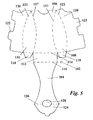
- Figure 9 shows another pouch 501 constructed to control the filling process to exclude air from the pouch 501.
- the pouch 501 is provided with a shape memory element 521 comprising a flat metal strip in the form of a coil spring.
- the element 521 is built into the pouch 501 during manufacture so that the pouch 501 rolls up on itself towards a filler opening 523 to exclude air from the pouch 501 when empty.
- the pouch 501 expands by unwinding against the biasing of the coil spring 521 which applies a force to control the filling process so that air is excluded from the pouch 501.
- the coil spring 521 causes the pouch 501 to roll back on itself to exclude air from the pouch. In this way, if only part of the contents of the pouch are dispensed, oxidation of the remaining product is prevented thereby maintaining the quality of the remaining product for dispense later.
- Figure 10a shows the configuration of the coil spring 521 when the pouch 501 is rolled-up (empty) and Figure 10b shows the configuration of the coil spring 521 when the pouch 501 is expanded by the introduction of product.
- the filler opening 523 may be provided with a flow restrictor (not shown) that allows the product to be dispensed in a controlled manner.
- the flow restrictor may comprise a valve arranged to control dispense of the produce.
- the valve may be incorporated in a screw cap (not shown) or similar closure for the filler opening 523.
- FIG 11 shows a pouch 601 constructed to contain more than one product.
- the pouch 601 has two compartments 625a, 625b separated by a membrane 627 formed by joining the opposed sidewalls of the pouch during manufacture by RF welding or heat welding.
- the compartments 625a, 625b are connected to a filler opening 623 configured to allow each compartment 625a, 625b to be filled separately.
- the filler opening is closed by a screw cap 629 that seals the opening and prevents the contents of the compartments 625a, 625b from mixing within the pouch 601.
- the membrane 627 may be constructed to withstand the pressure of product in the compartments when the pouch is filled but to rupture to allow the contents of the compartments to be mixed in the pouch 601 when an external force is applied to the pouch 601.
- manually squeezing the pouch 601 may cause the membrane 627 to rupture without compromising the integrity of the pouch 601 to contain the products. In this way, the contents of the compartments can be kept separate until it is desired to mix the products.
- FIG 12 shows another pouch 701 constructed to contain more than one product.
- the pouch 701 again comprises two compartments 725a, 725b separated by a membrane 727 but in this case each compartment has a separate filler opening 723a, 723b closed by a respective filler cap 729a, 729b such that each compartment can be filled separately the contents of the compartments can be dispensed separately.
- FIG. 13 shown a pouch 801 constructed to contain different portion sizes.
- the pouch 801 has two compartments 825a, 825b separated by a membrane 827.
- the compartments 825a, 825b are arranged so that compartment 825a fills first with product introduced via filler opening 823 and membrane 827 is constructed to rupture when pressure or volume of product in the compartment 825a exceeds a pre-determined level.
- the pouch can be filled to contain product in compartment 825a only without rupturing the membrane or to contain product in both compartments 825a, 825b by rupturing the membrane 827 during the filling process.
- the same pouch can be used to contain and dispense two different portion sizes.
- the membrane 827 extends vertically and the compartments 825a,825b are arranged side-by-side.
- the membrane extends horizontally so that the compartments are arranged one above the other.
- the membrane may be formed by welding opposed surfaces of the pouch together, for example heat welding. The welding operation may be carried out prior to the filling operation.
- one size of pouch can be adapted to the required portion size prior to dispense of product into the pouch.
- Any suitable means may be employed to control the welding operation.
- the welding operation may be incorporated into a machine for filling the pouch so as to be responsive to selection of a desired portion size.
- the welding operation may be carried out during or after the filling process.
- a pouch may be provided with separate compartments containing different products by welding the pouch after each product has been introduced into the pouch to confine the product within a sealed compartment.
- pouches may be filled with several products that are to be kept apart until it is desired to mix the products by rupturing the membrane separating the compartments.
- the welding operation may be incorporated into a machine for filling the pouch.
- compartments may be provided connected by suitable means to allow progressive filling of the compartments to provide any one of a range of portion sizes.
- suitable means to allow progressive filling of the compartments to provide any one of a range of portion sizes.
- Other constructions of pouches with compartments to keep products or product components separate until it is desired to mix the contents of the compartments or to allow variable portion sizes to be packaged in the same pouch can be employed.
- Figures 14a and 14b show filling a pouch 901 through a dip-tube 929 that initially extends to the lower end of the pouch 901 and one or both of the pouch 901 and dip-tube 929 is movable relative to the other whereby the dip-tube 929 is gradually withdrawn from the pouch 901 as the product is introduced so that the end of the dip-tube 929 remains below the surface of the product in the pouch 901.
- This method of filling reduces the occurrence of foaming and/or break-out of dissolved gas in the product and is especially suitable for filling the pouch with a product containing a dissolved gas such as a carbonated beverage.
- the pouch may be filled while controlling expansion of the pouch.
- rollers or other suitable means may be employed with a gap between the rollers to allow product to flow so that the pouch can be filled from the bottom up.
- the pouch may be located in a cavity filled with a fluid that is gradually removed from the cavity as the pouch is filled. The fluid may act on one or both sides of the pouch to control expansion of the pouch as it fills.
- the volume of fluid removed from the cavity equals the volume of product introduced into the pouch and may be used to control filling of the pouch to a desired volume. Controlling expansion of the pouch during filling may be beneficial where the product contains a dissolved gas such as a carbonated beverage to reduce the occurrence of foaming or break-out during the filling process.
- the filling process may be accompanied by illumination of the pouch and/or by sounds to provide a visual and/or audible indication of the filling process that can add to the theatre of dispense for the consumer.
- Illumination may be provided through a transparent or translucent portion of the pouch by positioning a light source (not shown) on the side of the pouch remote from the consumer so that the light shines through the pouch and any product in the pouch.
- a light source not shown
- the illumination and/or sound may be used throughout the filling process or at a pre-determined stage, for example to indicate the start and/or finish of the filling process.
- Many options and combinations of illumination and/or sounds to enhance the filling process are envisaged and include varying the intensity or colour of the illumination and varying the volume and tempo of the sound
- the flowable bulk material may be a chilled beverage or a partially or semi frozen beverage - often referred to as slush beverage - or alternatively may be a hot beverage.
- Partially or semi-frozen beverages may have an ice content formed from the beverage itself or by the addition of an ice slurry to the beverage.
- the ice content may be formed before, during or after filling the pouch with the beverage.
- the beverage may be a still beverage or a carbonated beverage and it may be an alcoholic beverage or a non-alcoholic beverage.
- the flowable bulk material may be a food product such as soup, ice cream, sorbet.
- Alcoholic drinks may include beer, lager, cider, wine, alcopops such as Bacardi Breezer (RTM), Smirnoff Ice (RTM), spirits and combinations of a spirit and mixer, for example gin and tonic.
- Non-alcoholic drinks may include still or carbonated water with or without additional flavourings, fruit juices, fruit drinks such as J20 (RTM), and other hot or cold drinks.
- Beverages may have a range of viscosities from low viscosity products such as liquids to high viscosity semi-solid or paste-like products such as milkshakes.
- Both alcoholic and non-alcoholic drinks may be provided with an ice content either formed from the drink itself or by mixing ice or an ice slurry with the beverage.
- An ice content may be formed from the drink itself by freezing the drink in a freeze cylinder or similar apparatus or by dispensing the drink in a super-cooled condition and subjecting it to a shock by ultrasonics or other suitable means such as injection of carbon dioxide gas or other additive that will cause a phase change creating ice in the drink.
- the sleeve may be pre-printed with product specific information for selection and use of the appropriate sleeve when dispensing a beverage.
- the sleeve may be blank or pre-printed with non-product specific information and the product specific information applied to the sleeve when the beverage is dispensed.
- the product specific information may be printed on the sleeve or on a label to be attached to the sleeve.
- the sleeve may be omitted and the product specific information applied to the pouch, for example by printing on the pouch or printing a label to be attached to the pouch.
- the invention has particular application to beverages, it may also be used to package and serve other flowable bulk materials, including food products such as soups, ice cream, sorbet which may vary from a low viscosity to a high viscosity.
Landscapes
- Engineering & Computer Science (AREA)
- Mechanical Engineering (AREA)
- Packages (AREA)
- Closures For Containers (AREA)
Abstract
Description
- This invention relates to the packaging and delivery of flowable bulk materials. The invention has particular, but not exclusive application, to a sleeve arranged to receive a pouch in which the flowable bulk material is contained a method and apparatus for filling the pouch, and the configuration of the pouch for packaging a range of portion sizes and/or for dispense of multiple products or product components/ingredients with or without mixing within the pouch.
- The invention has application to a wide range of flowable bulk materials including, but not limited to, bulk flowable materials intended to be consumed such as beverages and other flowable food products such as soups, sauces, syrups, ice cream, sorbet and the like. For convenience the invention is described hereinafter with reference to the packaging and delivery of beverages but it will be understood that we do not intend to be limited thereto and that the invention extends to and includes any flowable bulk materials including products that can be consumed either directly or when added to another food product and products that are not intended to be consumed such as sun creams and the like.
- Both alcoholic and non-alcoholic beverages are traditionally sold pre-packaged in plastic or glass bottles, cans or pre-filled cartons. They are sold through different retail outlets such as shops, bars, cafes and restaurants or through vending machines. There are a number of problems associated with the packaging traditionally used, primarily the amount of space required by a retailer to store the packaged beverages. The majority of retailers store beverages in refrigerated cabinets with a limited capacity. The shape of pre-packaged beverages, such as a bottle, is inefficient for storage thereby limiting the amount of stock, and therefore the range, that can be offered by the retailer. Furthermore, the inefficient storage shape of the packaging increases the space required for transport of the beverages. Pre-packaging a beverage before supplying to a retailer also means that the brand owner protects the profit in the branded beverage.
- An additional problem is the large amount of energy consumed in keeping the cabinets refrigerated and there can also be problems with stock rotation. For example, most bars use refrigerators that are both stocked from the front and emptied from the front, often leaving beverages at the back of the cabinet for long periods of time, which can lead to waste. The packaging itself also generates a large amount of waste and this can result in problems associated with waste management and the disposal of waste containing a number of different materials.
- It is known to provide a plastic pouch arranged to contain a beverage. A beverage can be dispensed into the pouch at the point of sale or, alternatively, the pouches can be provided pre-filled. However, the pouches can be unstable and difficult to handle, especially if containing a particularly hot or cold beverage. It may also prove difficult to sufficiently distinguish different brands of beverages.
- In one aspect, the present invention provides a method of packaging a bulk flowable material at the point of sale comprising providing a flexible pouch, filling the pouch with bulk flowable material and providing the pouch with an indication of the contents before, during or after filling the pouch. The invention also provides apparatus for carrying out the method.
- In one arrangement, the indication of the contents may be applied to the pouch, for example by printing on the material of the pouch or by attaching a label to the pouch. For example, apparatus for filling the pouch may include a printing station before or after the filling head for printing details of the contents onto the pouch itself or onto a label that is attached to the pouch by adhesive or other suitable means prior to dispensing the filled pouch.
- In this way, blank pouches or pouches carrying information common to all products to be dispensed can be provided for filling and labelling with specific details of the type of product being applied to the pouch at the point of dispense. As a result, non-product specific pouches can be supplied and the product specific information applied in response to selection of a particular product to be dispensed. This simplifies packaging of different products at the point of sale with resulting advantages for the retailer. Also the consumer benefits from the packaging of product dispensed at the point of sale thereby ensuring product freshness.
- The pouch may be made of transparent or translucent material and arranged so that the customer can see the contents as the pouch is being filled. This may add to the "theatre" of dispense, especially where dispense is accompanied by a change in the characteristics of the product in the pouch, for example where ice or other special effects are created in the product. In one preferred arrangement, the contents of the pouch can be illuminated with light from the side remote from the customer and this may further enhance the "theatre" of dispense. Alternatively or additionally, the pouch may be provided with a reflective or other suitable surface onto which an image or other special effect can be displayed to the customer while dispensing a product to enhance the "theatre" of dispense. Alternatively or additionally, the pouch may incorporate temperature responsive materials that change colour (thermochromic materials) or some other change to the appearance of the pouch when a cold or hot product is added to the pouch thereby creating a visual effect to enhance the "theatre" of dispense.
- In another arrangement, the indication of the contents of the pouch may be provided on packaging for the pouch itself. The packaging may be in the form of a sleeve in which the pouch is received. The indication of the contents may be applied to the sleeve, for example by printing on the sleeve or by attaching a label to the sleeve. For example, apparatus for filling the pouch may include a printing station for printing details of the contents onto the sleeve or onto a label that is attached to the sleeve by adhesive or other suitable means. The filled pouch and printed sleeve may be dispensed separately and the pouch placed in the sleeve by hand. Alternatively, the filled pouch may be dispensed already within the printed sleeve. With this arrangement, the apparatus for filling the pouch and printing the sleeve may be combined or separate filling and printing apparatus may be provided.
- In this way, blank sleeves or sleeves carrying information common to all products to be dispensed can be provided for labelling with specific details of the type of product to be dispensed into the pouch at the point of dispense. As a result, non-product specific sleeves can be supplied and the product specific information applied in response to selection of a particular product to be dispensed. This simplifies packaging of different products at the point of sale with resulting advantages for the retailer. Also the consumer benefits from the packaging of product dispensed at the point of sale thereby ensuring product freshness.
- The pouch is preferably made of transparent or translucent material and the sleeve arranged so that, when the pouch is filled in the sleeve, the customer can see the contents of the pouch through a window as the pouch is being filled. This may add to the "theatre" of dispense, especially where dispense is accompanied by a change in the characteristics of the product in the pouch, for example where ice or other special effects are created in the product. In a preferred arrangement, the sleeve is provided with windows in front and rear panels. With this arrangement, the contents of the pouch can be illuminated with light from the side remote from the customer and this may further enhance the "theatre" of dispense. Alternatively or additionally, the sleeve may be provided with a reflective or other suitable surface onto which an image or other special effect can be displayed to the customer while dispensing a product to enhance the "theatre" of dispense. Alternatively or additionally, the sleeve may incorporate temperature responsive materials that change colour (thermochromic materials) or some other change to the appearance of the sleeve when a cold or hot product is added to the pouch thereby creating a visual effect to enhance the "theatre" of dispense.
- Accordingly, the present invention also provides a sleeve for a pouch for a flowable bulk material, the sleeve being configured to define a cavity arranged to receive the pouch.
- In one embodiment, the sleeve comprises a flexible member made of materials such as paperboard materials, for example cardboard, especially corrugated cardboard. However, this is not essential and any one of a number of other suitable materials may be used including plastic and/or metallic film materials. The sleeve may comprise a single sheet of the material. The sheet of material may be divided into a plurality of panels and at least one panel may be fastened to another panel to define the cavity. Alternatively, the sheet of material may comprise a single panel, one part of which may be fastened to another to define the cavity. The material may be fastened to secure the sleeve in the erected condition using interlocking formations such as tabs, tongues and the like, or adhesive such as one or more adhesive stripes. Where provided, the adhesive stripe(s) may be protected by a removable cover strip until it is required to assemble the sleeve. It will be understood that any suitable fastening means or combination of fastening means may be employed. The erected sleeve may be self-supporting allowing the sleeve to stand on a surface while retaining a degree of flexibility such that the sides of the sleeve can be easily compressed thereby compressing the pouch to assist discharge of the product contained in the pouch. This may be particularly beneficial for products having a relatively high viscosity such as milkshakes or ice cream that can be squeezed out of the pouch by compressing the sleeve.
- In another embodiment, the sleeve comprises a rigid or semi-rigid member made of materials such as plastics, metals or elastomers, for example neoprene. The rigid or semi-rigid member may be formed by any suitable means such as injection moulding plastics or elastomers. The formed sleeve may be self-supporting capable of standing on a surface with the pouch supported therein and may provide a container such as a cup into which the contents of the pouch may be poured for consumption. Thus, the sleeve may serve as packaging for carrying the pouch with the product therein until it is desired to consume the product when the pouch can be removed from the sleeve and the contents emptied into the sleeve.
- The sleeve may have an opening at one end such that the pouch can be inserted into the cavity in the sleeve. In one arrangement, the base of the sleeve is open allowing the sleeve to slide over the pouch. In another arrangement, the top of the sleeve is open allowing the pouch to be dropped into the sleeve. In a further arrangement, the sleeve may be assembled around the pouch, or the pouch may be inserted into a partially assembled sleeve. The pouch may be pre-filled before locating in the sleeve, or alternatively the pouch may be filled when in the sleeve.
- The sleeve may further comprise means to retain the pouch in the sleeve. For example, where the base of the sleeve is open, the sleeve may include a panel, flap or projections arranged to extend across and at least partially close the base to support and retain the pouch in the sleeve. Alternatively or additionally, the sleeve may define an opening for a neck or spout of the pouch and the opening may be configured to engage the neck or spout to retain the pouch in the sleeve, for example the neck or spout may be a snap fit in the aperture. Alternatively or additionally, the sleeve may be provided with one or more adhesive regions that secure the pouch to the sleeve within the cavity. The adhesive regions may be provided with a removable cover strip until it is required to attach the pouch to the sleeve.
- Preferably, the sides of the sleeve are tapered and may be tapered out towards the bottom of the sleeve. This arrangement results in a sleeve that opens out at the bottom to provide a stable base for standing the sleeve on a surface such as a table with the pouch located in the cavity.
- Alternatively, or additionally, at least two of the panels may have a curved shape. For example, in one plane the sleeve may be narrower at a centre portion than at either the top or bottom to provide a more comfortable shape to hold.
- Preferably, the material of the sleeve is thermally insulating to reduce heat transfer to or from the pouch. In this way chilled contents of the pouch remain cold and heated contents remain hot. In addition, the thermal insulation properties of the sleeve allow the pouch to be held comfortably when the contents of the pouch are chilled or heated.
- The sleeve may be pre-printed before assembly. For example, the sleeve may be printed with a brand name or logo to correspond with a beverage on offer at a retail outlet. The sleeve may further comprise a window in at least one panel, arranged to enable the contents of the beverage pouch to be seen.
- The pouch is preferably made of transparent or translucent material and the sleeve arranged so that, when the pouch is filled in the sleeve, the customer can see the contents of the pouch through the window as the pouch is being filled. This may add to the "theatre" of dispense, especially where dispense is accompanied by a change in the characteristics of the product in the pouch, for example where ice or other special effects are created in the product. In a preferred arrangement, the sleeve is provided with windows in front and rear panels. With this arrangement, the contents of the pouch can be illuminated with light from the side remote from the customer and this may further enhance the "theatre" of dispense. Alternatively or additionally, the sleeve may be provided with a reflective or other suitable surface onto which an image or other special effect can be displayed to the customer while dispensing a product to enhance the "theatre" of dispense. Alternatively or additionally, the sleeve may incorporate temperature responsive materials that change colour (thermochromic materials) or some other change to the appearance of the sleeve when a cold or hot product is added to the pouch thereby creating a visual effect to enhance the "theatre" of dispense.
- The sleeve may be configured to fit in a carrier and the carrier may be capable of supporting a plurality of sleeves having pouches located therein. For example, the carrier may comprise a tray having recesses in which the base end of the sleeve is received to support the sleeve. In this way, several pouches may be carried in a safe and convenient manner that reduces the risk of the contents of the pouches being spilled.
- According to a yet another aspect of the invention, there is provided a system for packaging and delivery of a bulk flowable material, the system comprising a pouch for the bulk flowable material and a sleeve configured to define a cavity in which the pouch is received
- Preferably, the sleeve is as described above in connection with the preceding aspect of the invention. The pouch may comprise a flexible bag of a food-grade material provided with a neck or spout through which the flowable bulk material can be introduced to fill the pouch and withdrawn to consume the flowable bulk material. The neck or spout may be provided with a closure to retain the flowable bulk material in the pouch until it is desired to consume the flowable bulk material. The closure may comprise a screw cap, flip-top cap, sports cap, push-fit cap or any other suitable closure device. The closure may be re-closable to allow the neck or spout to be closed when the contents of the pouch have been partially consumed. The closure may be configured to allow the pouch to be employed with automatic pouch filling equipment.
- The bulk flowable material may be a beverage, for example an alcoholic beverage such as beer, lager, cider, wine, spirits (with or without a mixer), alcopop, cocktail or a non-alcoholic beverage such as still or carbonated water with or without additional flavouring, or fruit juice. The beverage may be chilled for dispense into the pouch. The beverage may be a semi-frozen beverage sometimes referred to as a slush beverage. The semi-frozen beverage may be formed by partially freezing the beverage to produce an ice content prior to filling the pouch. Alternatively or additionally, the semi-frozen beverage may be formed in the pouch. For example we may dispense a supercooled beverage and subject the beverage to a shock such as by ultrasonics, injection of carbon dioxide gas or other additive that will cause ice crystals to nucleate in the supercooled fluid when the beverage is dispensed and/or when the beverage is in the pouch to cause formation of an ice content. Alternatively or additionally, we may add an ice slurry to the beverage when the beverage is dispensed and/or when the beverage is in the pouch. The beverage may be a hot beverage such as tea, coffee, chocolate. Other consumable flowable hot or cold products that may be contained in the pouch include soups, milkshakes, ice cream, sorbet etc.
- According to a still further aspect of the invention, there is provided a method of serving a flowable bulk material comprising the steps of selecting a flowable bulk material, dispensing the flowable bulk material into a pouch, selecting a sleeve corresponding to the selected flowable bulk material and inserting the pouch into the sleeve.
- The flowable bulk material may be a chilled beverage or a partially or semi frozen beverage - often referred to as slush beverage - or alternatively may be a hot beverage. Where the flowable bulk material is a beverage, it may be a still beverage or a carbonated beverage and it may be an alcoholic beverage or a non-alcoholic beverage.
- According to another aspect of the invention, there is provided a method of dispensing a flowable bulk material into a pouch at the point of sale or delivery of the beverage for consumption.
- The flowable bulk material may be a chilled beverage or a partially or semi frozen beverage - often referred to as slush beverage or alternatively may be a hot beverage. Partially or semi-frozen beverages may have an ice content formed from the beverage itself or by the addition of an ice slurry to the beverage. The ice content may be formed before, during or after filling the pouch with the beverage. The beverage may be a still beverage or a carbonated beverage and it may be an alcoholic beverage or a non-alcoholic beverage. The flowable bulk material may be a food product such as soup, ice cream, sorbet.
- The invention also includes a pouch filled with a flowable bulk material suitable for consumption at the point of sale or delivery.
- The invention further includes apparatus for filling a pouch with a flowable bulk material. The apparatus may also provide the pouch with a sleeve identifying the contents of the pouch. The apparatus may be provided for packaging products at the point of sale in a shop or other retail outlet for supply to customer order. Alternatively, the apparatus may be embodied in a vending machine or the like with suitable controls for customer selection of the product to be packaged and dispensed.
- From yet another aspect of the invention, there is provided controlled filling of a pouch with a bulk flowable product to exclude air from the pouch and/or to prevent break-out of gas from the product.
- Air within the pouch can lead to deterioration of the product due to oxidation which is undesirable and controlled filling to exclude air may improve product quality and/or shelf-life.
- Break-out of gas from the product when filling the pouch with a carbonated beverage can lead to foaming and a reduction in carbonation levels which is undesirable and controlled filling to prevent break-out may improve the filling process and/or product quality.
- Controlled filling of the pouch may be achieved by filling the pouch while applying an external force to the pouch such that air is excluded from the pouch. In the case of a carbonated product, the external force may apply a back pressure at least equal to the equilibrium pressure of the dissolved gas within the product so as to reduce or prevent break-out of the gas, typically carbon dioxide but may be nitrogen or other gas or mixture of gases that complies with food standards.
- The external force may be applied in any suitable manner and may be responsive to pressure and/or temperature via any suitable control system for monitoring pressure and/or temperature and adjusting the external force accordingly.
- In one arrangement, the pouch may be placed between a pair of plates that are urged towards each other so that the pouch and product within the pouch is squeezed between the plates in a controlled manner. One of the plates may be fixed and the other plate urged towards the fixed plate by any suitable device that allows the pouch to expand as it is filled with product while applying a back pressure to exclude air.
- In another arrangement, the bag may pass between a pair of rollers so that the pouch and product within the pouch is squeezed between the rollers in a controlled manner. The pouch may move relative to the rollers or vice versa. One of the rollers may be fixed and the other roller urged towards the fixed roller by any suitable device that allows the pouch to expand as it is filled with product while applying a back pressure to exclude air.
- Suitable devices for controlling the external pressure applied by the plates or rollers include springs, pneumatic or hydraulic cylinders, or weight controlled loads.
- Controlled filling of the pouch may be achieved by configuring the pouch to exclude air during product filling and preferably also during product dispense.
- In one arrangement, the pouch may contain air prior to filling and product is introduced to the pouch to displace the air from the pouch. For example, the air may be displaced through a valve that closes when the pouch is filled. Thus, the valve may be closed by the pressure or volume of product in the pouch so as to exclude air from the pouch.
- In another arrangement, the pouch is provided in a collapsed, evacuated condition in which air is excluded and product is introduced to the pouch to expand the pouch from the collapsed condition without introducing air. The pouch may be made of shape memory material or include a shape memory element that tends to return the pouch to the collapsed condition.
- In this way, the shape memory material or element provides a force that resists expansion of the pouch to control filling of the pouch and exclude air and which causes the pouch to tend to return to its original, collapsed condition as product is dispensed to exclude air from the pouch.
- In a preferred arrangement, the shape memory element causes the pouch to roll up on itself, for example the shape memory element may comprise a flat metal or plastic strip in the form of a coil spring.
- Alternatively, the shape memory element may cause the pouch to fold up on itself, for example the shape memory element may comprise a flat metal or plastic strip with sections connected by a resilient hinge.
- Alternatively, the shape memory element may cause the pouch to collapse (concertina) on itself, for example the shape memory element may comprise a metal or plastic strip in the form of a bellows.
- In these arrangements, dispense of product when the pouch is opened is preferably controlled by providing a valve or similar flow restrictor on the outlet so that the force of the shape memory element does not cause the product to be dispensed in an uncontrolled manner.
- From still another aspect of the invention there is provided controlled filling of a pouch with a bulk flowable product to provide a selected portion size.
- Bulk flowable products, especially beverages, are normally dispensed in a range of portion sizes that require separate containers for each size and controlled filling to a selected portion size may allow one pouch size to be used for dispense of a range of portion sizes.
- Controlled filling of the pouch to a selected portion size may be achieved by providing the pouch with a plurality (at least two) of individual compartments that are filled in sequence according to the selected portion size. For example adjacent compartments may be separated by means responsive to pressure or volume of product in one of the compartments.
- Such means may comprise a membrane that ruptures to connect adjacent compartments when the pressure or volume of product in one of the compartments exceeds a pre-determined level.
- Alternatively, such means may comprise a valve that opens to connect adjacent compartments when the pressure or volume of product in one of the compartments exceeds a pre-determined level.
- In either arrangement, the pre-determined level may be achieved when the compartment is overfilled, i.e. when the volume of product introduced exceeds the portion size of the compartment. In either arrangement, the pouch may have a "concertina" type construction that opens out as successive compartments are filled.
- The pouch may be provided with compartments of the same or different portion sizes according to the range of portion sizes that can be selected for dispense.
- Where the compartments are separated by a rupturable membrane, this may comprise a weld connecting wall portions of the pouch. Such welds may be formed in a pouch made of plastics material during manufacture of the pouch by any suitable means, for example welds may be formed by RF welding or by heat welding.
- Where the compartments are separated by a valve, the valve may be of any suitable type, for example a bursting disc or other element responsive to pressure. The valve could comprise one or more slits that is normally closed up to a pre-determined pressure at which the slit opens to allow transfer of product from one compartment to another.
- From yet another aspect of the invention, there is provided controlled filling of a pouch with two or more bulk flowable products or components of a bulk flowable product.
- Bulk flowable products, especially beverages, typically comprise a mixture of components such as a diluent (still or carbonated water) and a concentrate (syrup or flavour) which may have a limited shelf-life after mixing.
- Thus, by keeping the products or components separate prior to dispense, product quality and shelf-life may be improved. Also, arranging for the products or components to be mixed at the time of use, enables interesting visual effects to be achieved that can enhance the "theatre" of dispense for the consumer.
- Controlled filling of the pouch with at least two bulk flowable products or components of a bulk flowable product may be achieved by providing the pouch with separate compartments into which the separate products or components of a product are introduced.
- The compartments may be configured to keep the contents separate within the pouch and to allow the contents to be dispensed separately without mixing in the pouch. For example, each compartment may be provided with means for introducing and dispensing the contents separately from the other compartments.
- Thus, the compartments may have separate filler openings each having a removable lid for opening/closing the opening to fill the compartment and dispense the contents of the compartment separately from the other compartments. In this way, the products or product components can be dispensed individually into a cup or other receptacle if desired.
- Alternatively, the compartments may be configured to keep the contents separate within the pouch and allow the contents to be dispensed together. For example, the compartments may have separate filler openings that converge to and are covered by a single removable lid.
- The lid may seal the opening to each compartment to prevent the contents of the compartments mixing before dispense. With this arrangement, the contents of all the compartments are dispensed together and mix within the cup or other receptacle into which they are dispensed.
- In a modification, the lid may be removed and a cap fitted having a chamber into which the contents of the compartments flow and mix before being dispensed into the cup or other receptacle via a suitable nozzle.
- In a further modification, the lid may be configured to open selectively the filler openings whereby the contents of the compartments may be dispensed separately or in combination with the contents of one or more other compartments.
- Alternatively, the compartments may be configured to keep the contents separate within the pouch during filling and to allow the contents of selected compartments to be mixed within the pouch prior to or at the time of dispense.
- In one arrangement, the compartments may be separated by a membrane capable of resisting the internal pressure generated by the contents of the compartment when the pouch is filled but which can be ruptured by applying an external force to the pouch to allow the contents of the compartments to mix within the pouch.
- The external force may be applied by compressing the pouch, for example manually squeezing the pouch until the membrane ruptures. The membrane may be configured to rupture when the external force is applied to a specific region or regions of the pouch. The membrane may be formed during manufacture of a plastics pouch by RF welding or heat welding.
- In another arrangement, the compartments may be separated by a valve that can be opened to allow the contents of the compartments to mix within the pouch. The valve may comprise a pressure responsive element that opens in response to a pressure differential created by applying an external force to the pouch.
- The valve may allow flow in one direction only to allow the contents of one compartment to be added another compartment but not allow flow in the opposite direction. In this way, varying amounts of the contents of one compartment can be added to and mixed with the contents of another compartment.
- In another arrangement, the compartments may be separated by a transfer tube that allows the contents of one compartment to be added to the contents of another compartment prior to or during dispense.
- The tube may be closed to prevent transfer in any orientation of the pouch until it is desired to mix the components by opening the tube to connect the compartments.
- Alternatively the tube may be open and configured to prevent transfer until the pouch is placed in a particular orientation such as by inverting the pouch for dispense of product from the pouch whereby the contents of one compartment can flow into the other compartment through the tube.
- From a still further aspect of the invention, there is provided controlled filling of a pouch with a bulk flowable product with a visual and/or audible indication of the filling process.
- A visual and/or audible indication of the filling process may be employed to provide interesting effects for the consumer during dispense that may add to the consumer's perception of the product and desire to purchase the product by enhancing the theatre of dispense.
- The visual and/or audible indication of the filling process may also be used as an aid to indicate when the filling process is complete in different situations.
- Thus, for self-service the visual and/or audible indication may be used to inform the consumer that the product has been dispensed and the pouch can be removed from the filling station.
- Alternatively, for attendant service, the visual and/or audible indication may be used to allow the attendant to leave a pouch while filling and return to the filling station to remove the pouch to give to the consumer when the pouch has been filled.
- The pouch may be made of a transparent or translucent material, typically plastics, or have a transparent or translucent section through which the pouch can be illuminated from the side remote from the consumer.
- The illumination may change during the filling process. For example, the colour and/or intensity may change to provide different visual effects for the consumer and/or to indicate when the filling process is complete. For example, the illumination may operate like traffic lights changing from red when an empty pouch is connected to a filling station to amber during the filling process and then green when the filling process is completed.
- The change in transmission of the light as the pouch fills with product may be used to detect when the pouch has been filled to a desired level. Completion of the filling process may be accompanied by an audible indication that the pouch has been filled and can be removed from the filling station. For example a buzzer or bell may be activated when the filling process is complete.
- Alternatively or additionally, the filling process may be accompanied by sounds such as music together with or in place of any illumination of the pouch. The sound may change during the filling process to provide different audible effects for the consumer and/or to indicate when the filling process is complete. For example, the volume and/or tempo of the music may change as the pouch fills.
- Other visual and/or audible effects can be employed to accompany the filling process and/or to indicate any stage of the filling process to the consumer and/or attendant. The visual and/or audible effects may be the same or different for dispense of different drinks. For example, illumination with different colours or different sounds or music may be used for different products.
- Preferred embodiments of the invention will now be described, with reference to the accompanying drawings, in which;
-
Figure 1 is a front view of an assembled sleeve and beverage pouch; -
Figure 2 shows a blank for constructing the sleeve ofFigure 1 ; -
Figure 3 is a front view of an assembled sleeve with a viewing window; -
Figure 4 is a front view of an alternative assembled sleeve; -
Figure 5 shows a blank for constructing the sleeve ofFigure 4 ; -
Figure 6 shows a first embodiment of apparatus for controlled filling of a pouch; -
Figure 7 shows a second embodiment of apparatus for controlled filling of a pouch; -
Figure 8 shows a method for controlled filling of a pouch; -
Figure 9 shows a pouch configured for controlled filling; -
Figures 10a and 10b show the pouch ofFigure 9 expanded and collapsed; -
Figure 11 shows a pouch configured to contain more than one product or product component; -
Figure 12 shows an alternative pouch configured to contain more than one product or product component; -
Figure 13 shows a pouch configured to contain different portion sizes; and -
Figures 14a and 14b show a pouch and dip-tube for filling the pouch. - Referring to
Figures 1 and2 , according to a first embodiment of the invention, abeverage pouch sleeve 2 comprises a single sheet of folded cardboard. The sleeve comprises afront panel 6, aback panel 4 and two shapedpanels 8, 10. The front and back panels, 4, 6 are joined at a top edge and folded about ascore line 12 until thebottom edge 18 of theback panel 4 is substantially level with thebottom edge 20 of thefront panel 6. One shapedpanel 10 extends from a side edge of theback panel 4 and is folded about ascore line 14 until it overlaps thefront panel 6. Similarly, a shaped panel 8 extends from a side edge of thefront panel 6 and is folded about ascore line 16 until it overlaps theback panel 4. - The shaped
panels 8, 10 are secured to the outer faces of the front andback panels back panels beverage pouch 22 can be inserted. The outer faces of thesleeve 2 are printed with a design or brand name corresponding to a beverage on sale in a particular retail outlet. The cardboard is die-cut and pre-printed before assembly into the sleeve. - In this embodiment, the
panels 8,10 are provided with one or more stripes of adhesive (not shown) such as a contact adhesive by means of which thepanels 8, 10 are adhered to the outer faces of thepanels panels 8, 10 to thepanels panels 8, 10 may be secured to thepanels - The sides of the front and
back panels - A
slit 24 is cut along thescore line 12 at a mid-way point and is arranged to allow the neck or spout 25 of thebeverage pouch 22 to pass through the top edge of the sleeve. The neck or spout 25 is provided with acap 26, for example a screw cap, that can be removed when the pouch is to be filled and attached to seal and retain the contents within thepouch 22. Thecap 26 can be removed when the contents of the pouch are to be consumed and may be re-attached to re-seal the pouch if the contents are only partially consumed. Theslit 24 may be configured to co-operate with the neck or spout 25 to retain thepouch 22 in thesleeve 2. For example the neck or spout 25 may be a snap fit in theslit 24. - Referring to
Figure 3 , in an alternative embodiment of the invention, thesleeve 2 includes a window 27 in at least one face, for example thefront face 6 of the sleeve. Thefront panel 6 is shaped to mirror the shape of the shapedpanel 10 such that, when assembled, the shaped edges of the twopanels - In use, the
beverage pouch 22 is filled with a selected beverage from a dispensing machine in a retail outlet. The pouch may be filled by hand or automatically. For example the pouch may be fed to a filler head part of an automated pouch filling system where thecap 26 is removed, the beverage dispensed into the pouch and thecap 26 re-attached. The retailer then selects thesleeve 2 corresponding to the selected beverage and slides thesleeve 2 over the filled pouch before handing to the customer.
Alternatively, the filled pouch and sleeve may be dispensed in a vending machine. - The
sleeves 2 andpouches 22 may be delivered flat-packed to the retail outlet, which considerably reduces the amount of storage space required. Asleeve 2 can then be erected on site as and when required. Sleeves with a number of different designs, brands or logos printed can be stored, to correspond with the range of beverages offered by the retailer. This system allows the beverages to be stored in chilled dispensers and dispensed as required, which is much more economical in the amount of storage space required than pre-filled bottles in refrigerated cabinets. This therefore reduces the amount of energy required to chill the beverages and allows a greater range of beverages to be stocked. - Referring to
Figures 4 and5 , in an alternative embodiment of the invention, thesleeve 102 comprises afront panel 106 attached along its bottom edge defined by ascore line 114 to arectangular base panel 112, which in turn is joined along ascore line 116 to aback panel 104. The front and back panels are shaped to have curved sides, curved inwardly from the base to substantially halfway along the length of the panel and then outwardly towards the top. This shaping makes the assembled sleeve more comfortable to hold. The front and back panels are folded about the score lines to extend upwards from thebase 112. - Two
side panels front panel 106 and are arranged to fold about score lines 117. The side panels are shaped to correspond with the shaping of the front and back panels and come to a point at the top. The base edges of theside panels base panel 112 and, when assembled,tabs 118 extending from the base of the side panels are secured to thebase panel 122 by adhesive or other suitable means. Thesolid base 112 provides a stable sleeve that can be stood on a surface. -
Tab portions 120 also extend from each of theside panels Tabs 122 are arranged to interlock to form a back portion. Theback panel 104 is then folded up behind the interlocking tabs, concealing them. - A
flap 124 extends from the top of theback panel 104, is folded over the top of the sleeve aboutscore line 126, and is secured to thefront panel 106 by adhesive or other suitable means. This secures each of the panels in their place, forming a box-like sleeve 102. Ahole 128 is cut alongscore line 126 between theback panel 104 and theflap 124 to allow the neck or spout of a beverage pouch to project outside of thesleeve 102 for attaching the cap. - In use, a beverage pouch is filled with a selected beverage as described above and inserted into the
appropriate sleeve 102. In this embodiment, the sleeve may be supplied assembled with an unfilled pouch within the sleeve and a beverage may be dispensed into the pouch through the neck or spout extending through thehole 128 in the sleeve with the cap removed and the cap attached to seal and retain the product in the pouch. Alternatively, the sleeve may be supplied unassembled and is assembled around a filled or unfilled pouch or may be supplied partially assembled, the pouch filled and placed into the partially assembled sleeve, and the remainder of the sleeve assembled around the pouch. For example, theflap 124 may be left open to allow the pouch to be inserted into thesleeve 102 before securing theflap 124 to thefront panel 106 by adhesive or other suitable means. - In addition to reducing storage space, the sleeve acts as a thermal insulator trapping a layer of air between the beverage pouch and the sleeve. This allows both hot and cold drinks to be dispensed into the pouch and handled safely. The cardboard may be corrugated to further improve the insulation provided by the sleeve.
- Cardboard is easily compressed and this allows more viscous products such as ice cream or milkshake to be dispensed into the pouch and squeezed out. The use of the pouch, which is enabled by the sleeve, is also more hygienic since there is limited handling and no oxidisation and also minimises the risk of carbonated drinks going flat. Furthermore, the production of waste is minimised and the cost of packaging production is competitive. Dispensing beverages on site also provides the retailer with a higher profit.
- It will be appreciated that the sleeves can be produced in a range of sizes, to accommodate pouches of varying portion sizes. For example, pouches may be 150ml, 200ml, 330ml, 400ml, 1 litre, 3 litres or any other suitable size. The sleeves may also be produced in a variety of shapes.
The shape may be distinctive of the type of beverage contained within the pouch or of the brand of the beverage. - It will also be appreciated that the sleeve may be used in combination with pouches of a variety of different shapes, sizes and materials. Furthermore, the pouches may comprise one of a number of different closing means, for example a screw cap, a sports cap or a seal. Alternatively, the pouch may comprise an opening means that is independent of an opening used for filling the pouch, such as a punch hole for use with a straw.
- Referring now to
Figure 6 , apouch 201 is shown positioned between a pair ofplates pouch 201 during the filling process in which the pouch is connected to thehead 206 of a filling station (not shown) for dispensing a product such as a beverage into thepouch 201. - The
pouch 201 is made of a flexible plastic film and is delivered to the filling station either manually or automatically according to the type of filling station employed. - Initially, the
empty pouch 201 is collapsed and contains no air. During the filling process, thepouch 201 expands as product is introduced. Expansion of thepouch 201 is resisted by theplates pouch 201. - The force is controlled to exclude air from the
pouch 201 and, in the case where the beverage is carbonated to prevent or reduce break-out of carbon dioxide from the beverage so that carbonation levels in the dispensed beverage are maintained and foaming is avoided. - External force is controlled to be at least equal to the equilibrium pressure of dissolved gas in the beverage and may be provided in one or more ways such as a pneumatic or
hydraulic ram 207, one ormore springs 209 or aweight load 211 applied to one or bothplates - The external force may be controlled during the filling process to apply a substantially constant pressure to the pouch and contents of the pouch during the filling process. This may be achieved by a suitable control system (not shown) responsive to appropriate sensors (not shown) which may include sensors for monitoring temperature and/or pressure.
- On completion of the filling process, the
pouch 201 is sealed by any suitable means such as a screw cap attached to a filler opening to exclude air from the pouch. In this way, oxidation of the pouch contents leading to deterioration of the pouch contents while stored in the pouch can be prevented or reduced so that shelf-life of the product and product quality may be improved. -
Figure 7 shows an alternative apparatus for controlling filling of apouch 301 to exclude air and prevent break-out of the carbon dioxide where the product is a carbonated beverage. In this embodiment, thepouch 301 is passed between a pair ofrollers pouch 301 during the filling process. - As shown the pouch and rollers move relative to one another to advance the pouch between the rollers as product is dispensed into the
pouch 301. - This may be achieved by moving one or both of the
pouch 301 androllers rollers pouch 301. -
Figure 8 shows apouch 401 constructed to control the filling process to exclude air from thepouch 401. In this embodiment, thepouch 401 is filled by introducing product via atube 417 that extends to the bottom of thepouch 401 and avalve 419 is provided at the upper end through which air displaced by the product is expelled. - The
valve 419 is designed to close when the pouch is filled with product. For example thevalve 419 may comprise a float operated ball valve that closes when the pouch is filled with beverage and thereby exclude air from the pouch. -
Figure 9 shows anotherpouch 501 constructed to control the filling process to exclude air from thepouch 501. In this embodiment, thepouch 501 is provided with ashape memory element 521 comprising a flat metal strip in the form of a coil spring. - The
element 521 is built into thepouch 501 during manufacture so that thepouch 501 rolls up on itself towards afiller opening 523 to exclude air from thepouch 501 when empty. - During filling the
pouch 501 expands by unwinding against the biasing of thecoil spring 521 which applies a force to control the filling process so that air is excluded from thepouch 501. - When product is dispensed from the
pouch 501, thecoil spring 521 causes thepouch 501 to roll back on itself to exclude air from the pouch. In this way, if only part of the contents of the pouch are dispensed, oxidation of the remaining product is prevented thereby maintaining the quality of the remaining product for dispense later. -
Figure 10a shows the configuration of thecoil spring 521 when thepouch 501 is rolled-up (empty) andFigure 10b shows the configuration of thecoil spring 521 when thepouch 501 is expanded by the introduction of product. - To prevent the product being dispensed in an uncontrolled manner by the force of the
coil spring 521 when thepouch 501 is opened, thefiller opening 523 may be provided with a flow restrictor (not shown) that allows the product to be dispensed in a controlled manner. - The flow restrictor may comprise a valve arranged to control dispense of the produce. The valve may be incorporated in a screw cap (not shown) or similar closure for the
filler opening 523. -
Figure 11 shows apouch 601 constructed to contain more than one product. As shown thepouch 601 has twocompartments membrane 627 formed by joining the opposed sidewalls of the pouch during manufacture by RF welding or heat welding. - The
compartments filler opening 623 configured to allow eachcompartment screw cap 629 that seals the opening and prevents the contents of thecompartments pouch 601. - In use, when the
cap 629 is removed, products in bothcompartments - In a modification, the
membrane 627 may be constructed to withstand the pressure of product in the compartments when the pouch is filled but to rupture to allow the contents of the compartments to be mixed in thepouch 601 when an external force is applied to thepouch 601. - For example, manually squeezing the
pouch 601 may cause themembrane 627 to rupture without compromising the integrity of thepouch 601 to contain the products. In this way, the contents of the compartments can be kept separate until it is desired to mix the products. -
Figure 12 shows another pouch 701 constructed to contain more than one product. In this embodiment, the pouch 701 again comprises twocompartments membrane 727 but in this case each compartment has aseparate filler opening respective filler cap -
Figure 13 shown apouch 801 constructed to contain different portion sizes. Thepouch 801 has twocompartments membrane 827. Thecompartments compartment 825a fills first with product introduced viafiller opening 823 andmembrane 827 is constructed to rupture when pressure or volume of product in thecompartment 825a exceeds a pre-determined level. - In this way, the pouch can be filled to contain product in
compartment 825a only without rupturing the membrane or to contain product in bothcompartments membrane 827 during the filling process. As a result, the same pouch can be used to contain and dispense two different portion sizes. In this embodiment, themembrane 827 extends vertically and thecompartments - In a modification, the welding operation may be carried out during or after the filling process. For example, a pouch may be provided with separate compartments containing different products by welding the pouch after each product has been introduced into the pouch to confine the product within a sealed compartment. In this way, pouches may be filled with several products that are to be kept apart until it is desired to mix the products by rupturing the membrane separating the compartments. Again, the welding operation may be incorporated into a machine for filling the pouch.
- Any number of compartments may be provided connected by suitable means to allow progressive filling of the compartments to provide any one of a range of portion sizes. Other constructions of pouches with compartments to keep products or product components separate until it is desired to mix the contents of the compartments or to allow variable portion sizes to be packaged in the same pouch can be employed.
-
Figures 14a and 14b show filling apouch 901 through a dip-tube 929 that initially extends to the lower end of thepouch 901 and one or both of thepouch 901 and dip-tube 929 is movable relative to the other whereby the dip-tube 929 is gradually withdrawn from thepouch 901 as the product is introduced so that the end of the dip-tube 929 remains below the surface of the product in thepouch 901. This method of filling reduces the occurrence of foaming and/or break-out of dissolved gas in the product and is especially suitable for filling the pouch with a product containing a dissolved gas such as a carbonated beverage. - Other arrangements for filling the pouch in a controlled manner are envisaged and within the scope of the invention. For example, we may fill the pouch while controlling expansion of the pouch. In one arrangement, rollers or other suitable means may be employed with a gap between the rollers to allow product to flow so that the pouch can be filled from the bottom up. In another arrangement, the pouch may be located in a cavity filled with a fluid that is gradually removed from the cavity as the pouch is filled. The fluid may act on one or both sides of the pouch to control expansion of the pouch as it fills. The volume of fluid removed from the cavity equals the volume of product introduced into the pouch and may be used to control filling of the pouch to a desired volume. Controlling expansion of the pouch during filling may be beneficial where the product contains a dissolved gas such as a carbonated beverage to reduce the occurrence of foaming or break-out during the filling process.
- In the above-described examples, the filling process may be accompanied by illumination of the pouch and/or by sounds to provide a visual and/or audible indication of the filling process that can add to the theatre of dispense for the consumer.
- Illumination may be provided through a transparent or translucent portion of the pouch by positioning a light source (not shown) on the side of the pouch remote from the consumer so that the light shines through the pouch and any product in the pouch.
- The illumination and/or sound may be used throughout the filling process or at a pre-determined stage, for example to indicate the start and/or finish of the filling process. Many options and combinations of illumination and/or sounds to enhance the filling process are envisaged and include varying the intensity or colour of the illumination and varying the volume and tempo of the sound
- As described herein the flowable bulk material may be a chilled beverage or a partially or semi frozen beverage - often referred to as slush beverage - or alternatively may be a hot beverage. Partially or semi-frozen beverages may have an ice content formed from the beverage itself or by the addition of an ice slurry to the beverage. The ice content may be formed before, during or after filling the pouch with the beverage. The beverage may be a still beverage or a carbonated beverage and it may be an alcoholic beverage or a non-alcoholic beverage. The flowable bulk material may be a food product such as soup, ice cream, sorbet.
- The invention has application for packaging and serving alcoholic and non-alcoholic drinks. Alcoholic drinks may include beer, lager, cider, wine, alcopops such as Bacardi Breezer (RTM), Smirnoff Ice (RTM), spirits and combinations of a spirit and mixer, for example gin and tonic. Non-alcoholic drinks may include still or carbonated water with or without additional flavourings, fruit juices, fruit drinks such as J20 (RTM), and other hot or cold drinks. Beverages may have a range of viscosities from low viscosity products such as liquids to high viscosity semi-solid or paste-like products such as milkshakes. Both alcoholic and non-alcoholic drinks may be provided with an ice content either formed from the drink itself or by mixing ice or an ice slurry with the beverage. An ice content may be formed from the drink itself by freezing the drink in a freeze cylinder or similar apparatus or by dispensing the drink in a super-cooled condition and subjecting it to a shock by ultrasonics or other suitable means such as injection of carbon dioxide gas or other additive that will cause a phase change creating ice in the drink.
- It will be understood that the invention is not limited to the embodiment above-described. For example, the sleeve may be pre-printed with product specific information for selection and use of the appropriate sleeve when dispensing a beverage. Alternatively, the sleeve may be blank or pre-printed with non-product specific information and the product specific information applied to the sleeve when the beverage is dispensed. For example the product specific information may be printed on the sleeve or on a label to be attached to the sleeve. In some applications of the invention, the sleeve may be omitted and the product specific information applied to the pouch, for example by printing on the pouch or printing a label to be attached to the pouch.
- Although the invention has particular application to beverages, it may also be used to package and serve other flowable bulk materials, including food products such as soups, ice cream, sorbet which may vary from a low viscosity to a high viscosity.
- Other applications of the invention will be apparent to those skilled in the art.
Claims (11)
- A sleeve for a pouch for a flowable bulk material, the sleeve being configured to define a cavity arranged to receive a pouch.
- A sleeve according to claim 1, wherein the sleeve is flexible and self-supporting, and comprises a single sheet of a material defining a plurality of panels for assembly of the sleeve.
- A sleeve according to claim 1 or claim 2, wherein the sleeve has an opening to the cavity for passage of a pouch and means arranged to retain a pouch in the sleeve.
- A sleeve according to claim 3 wherein the retaining means is cooperable a neck or spout of the pouch that projects from the sleeve.
- A sleeve according to any preceding claim, wherein the sleeve is tapered out towards the bottom of the sleeve.
- A sleeve according to any one of claims 1 to 4 wherein the sleeve is narrower at a centre portion than at either the top or bottom.
- A sleeve according to any preceding claim, further comprising a window arranged to enable the contents of the beverage pouch to be seen.
- Packaging for a flowable bulk material comprising a sleeve according to any preceding claim and a pouch received in the sleeve.
- A method of serving a flowable bulk material comprising the steps of selecting a flowable bulk material, dispensing the flowable bulk material into a pouch, selecting a sleeve corresponding to the selected flowable bulk material and inserting the pouch into the sleeve.
- A method for controlled filling of a pouch with a bulk flowable product to exclude air from the pouch and/or to prevent break-out of gas from the product.
- A method for controlled filling of a pouch with a bulk flowable product to provide a selected portion size.
Applications Claiming Priority (2)
| Application Number | Priority Date | Filing Date | Title |
|---|---|---|---|
| GBGB0624800.9A GB0624800D0 (en) | 2006-12-13 | 2006-12-13 | Packaging |
| GB0714618A GB0714618D0 (en) | 2007-07-27 | 2007-07-27 | Packaging |
Publications (3)
| Publication Number | Publication Date |
|---|---|
| EP1964785A2 true EP1964785A2 (en) | 2008-09-03 |
| EP1964785A3 EP1964785A3 (en) | 2012-09-19 |
| EP1964785B1 EP1964785B1 (en) | 2015-08-26 |
Family
ID=39666014
Family Applications (1)
| Application Number | Title | Priority Date | Filing Date |
|---|---|---|---|
| EP07254790.4A Not-in-force EP1964785B1 (en) | 2006-12-13 | 2007-12-12 | Packaging |
Country Status (1)
| Country | Link |
|---|---|
| EP (1) | EP1964785B1 (en) |
Cited By (30)
| Publication number | Priority date | Publication date | Assignee | Title |
|---|---|---|---|---|
| EP2514686A1 (en) * | 2011-04-22 | 2012-10-24 | Paul Bernard Newman | Adaptive packaging assembly for foodstuffs and method for packaging and processing a foodstuff in such an adaptive packaging assembly |
| WO2013169682A1 (en) * | 2012-05-07 | 2013-11-14 | The Procter & Gamble Company | Flexible containers |
| GB2503248A (en) * | 2012-06-20 | 2013-12-25 | Fernco Environmental Ltd | A method and apparatus for repairing a pipe. |
| WO2014025609A1 (en) * | 2012-08-06 | 2014-02-13 | The Procter & Gamble Company | Methods of making flexible containers |
| WO2014082161A1 (en) * | 2012-11-29 | 2014-06-05 | Beaver Machine Corporation | Bagging system for a vending machine |
| US8893518B2 (en) | 2011-04-25 | 2014-11-25 | Ics Solutions B.V. | Accelerating, optimizing and controlling product cooling in food processing systems |
| ITMI20130977A1 (en) * | 2013-06-13 | 2014-12-14 | Goglio Spa | PACKAGE IN FLEXIBLE MATERIAL FOR FOOD PRODUCTS TO BE TAKEN AFTER OVEN HEATING |
| CN104284844A (en) * | 2012-05-07 | 2015-01-14 | 宝洁公司 | Flexible containers |
| US9327867B2 (en) | 2013-08-01 | 2016-05-03 | The Procter & Gamble Company | Enhancements to tactile interaction with film walled packaging having air filled structural support volumes |
| US9688459B2 (en) | 2013-08-01 | 2017-06-27 | The Procter & Gamble Company | Disposable flexible containers having surface elements |
| US9758275B2 (en) | 2013-09-25 | 2017-09-12 | Graphic Packaging International, Inc. | Reinforced package |
| US9771176B2 (en) | 2013-09-25 | 2017-09-26 | Graphic Packaging International, Inc. | Reinforced package |
| US9844920B2 (en) | 2012-11-05 | 2017-12-19 | Graphic Packaging International, Inc. | Method and system for manufacturing bags |
| US9955711B2 (en) | 2011-05-20 | 2018-05-01 | Jbt Food & Dairy Systems B.V. | Method and apparatus for increased product throughput capacity, improved quality and enhanced treatment and product packaging flexibility in a continuous sterilizing system |
| US9957080B2 (en) | 2013-09-25 | 2018-05-01 | Graphic Packaging International, Llc | Reinforced package |
| US10023349B2 (en) | 2015-08-21 | 2018-07-17 | Graphic Packaging International, Llc | Reinforced package |
| WO2018224328A1 (en) * | 2017-06-07 | 2018-12-13 | Unilever Plc | Packaged frozen confection |
| US10294001B2 (en) | 2014-10-21 | 2019-05-21 | Graphic Packaging International, Llc | Package for a product |
| WO2020007657A1 (en) * | 2018-07-05 | 2020-01-09 | Fresenius Kabi Deutschland Gmbh | Enteral nutrition product |
| US10562675B2 (en) | 2015-04-29 | 2020-02-18 | Graphic Packaging International, Llc | Method and system for forming packages |
| US10640271B2 (en) | 2015-04-29 | 2020-05-05 | Graphic Packaging International, Llc | Method and system for forming packages |
| WO2020229520A1 (en) * | 2019-05-13 | 2020-11-19 | Nutritious Juices & Soups B.V. | Food product dispensing system |
| US11040798B2 (en) | 2017-08-09 | 2021-06-22 | Graphie Packaging International, LLC | Method and system for forming packages |
| US11059255B2 (en) | 2015-07-14 | 2021-07-13 | Graphic Packaging International, Llc | Method and system for forming packages |
| US11198534B2 (en) | 2019-01-28 | 2021-12-14 | Graphic Packaging International, Llc | Reinforced package |
| US11472146B2 (en) | 2013-08-01 | 2022-10-18 | The Procter & Gamble Company | Flexible containers having improved seam and methods of making the same |
| US11491755B2 (en) | 2018-07-09 | 2022-11-08 | Graphic Packaging International, Llc | Method and system for forming packages |
| US11576397B2 (en) | 2016-02-05 | 2023-02-14 | Conopco, Inc. | Frozen confection |
| US11981103B2 (en) | 2020-12-22 | 2024-05-14 | Graphic Packaging International, Llc | End flap engagement assembly for erecting cartons and related systems and methods |
| USD1042113S1 (en) | 2020-01-24 | 2024-09-17 | Graphic Packaging International, Llc | Reinforcing carton |
Families Citing this family (3)
| Publication number | Priority date | Publication date | Assignee | Title |
|---|---|---|---|---|
| US9241510B2 (en) | 2011-04-23 | 2016-01-26 | Ics Solutions B.V. | Apparatus and method for optimizing and controlling food processing system performance |
| US9131729B2 (en) | 2011-09-28 | 2015-09-15 | Ics Solutions B.V. | Safe and efficient thermal transfer media for processing of food and drink products |
| CA2925705A1 (en) | 2013-11-06 | 2015-05-14 | The Procter & Gamble Company | Flexible containers and methods of forming the same |
Citations (4)
| Publication number | Priority date | Publication date | Assignee | Title |
|---|---|---|---|---|
| DE8800400U1 (en) * | 1988-01-15 | 1988-02-25 | Graphia Hans Gundlach Gmbh, 4800 Bielefeld | Container for food, especially for French fries, made from a single piece of cardboard |
| EP0533648A1 (en) * | 1991-09-20 | 1993-03-24 | Fuji Photo Film Co., Ltd. | Disposable container for a fluid product and method of its manufacture |
| EP0686566A2 (en) * | 1994-06-01 | 1995-12-13 | Soremartec S.A. | A container, for example, for food products such as confectionery products |
| GB2419584A (en) * | 2004-11-01 | 2006-05-03 | Rapid Action Packaging Ltd | Packs for holding food items |
-
2007
- 2007-12-12 EP EP07254790.4A patent/EP1964785B1/en not_active Not-in-force
Patent Citations (4)
| Publication number | Priority date | Publication date | Assignee | Title |
|---|---|---|---|---|
| DE8800400U1 (en) * | 1988-01-15 | 1988-02-25 | Graphia Hans Gundlach Gmbh, 4800 Bielefeld | Container for food, especially for French fries, made from a single piece of cardboard |
| EP0533648A1 (en) * | 1991-09-20 | 1993-03-24 | Fuji Photo Film Co., Ltd. | Disposable container for a fluid product and method of its manufacture |
| EP0686566A2 (en) * | 1994-06-01 | 1995-12-13 | Soremartec S.A. | A container, for example, for food products such as confectionery products |
| GB2419584A (en) * | 2004-11-01 | 2006-05-03 | Rapid Action Packaging Ltd | Packs for holding food items |
Cited By (58)
| Publication number | Priority date | Publication date | Assignee | Title |
|---|---|---|---|---|
| US10252852B2 (en) | 2011-04-22 | 2019-04-09 | Jbt Food & Dairy Systems B.V. | Adaptive packaging for food processing systems |
| EP2514686A1 (en) * | 2011-04-22 | 2012-10-24 | Paul Bernard Newman | Adaptive packaging assembly for foodstuffs and method for packaging and processing a foodstuff in such an adaptive packaging assembly |
| US8893518B2 (en) | 2011-04-25 | 2014-11-25 | Ics Solutions B.V. | Accelerating, optimizing and controlling product cooling in food processing systems |
| US9955711B2 (en) | 2011-05-20 | 2018-05-01 | Jbt Food & Dairy Systems B.V. | Method and apparatus for increased product throughput capacity, improved quality and enhanced treatment and product packaging flexibility in a continuous sterilizing system |
| US9815258B2 (en) | 2012-05-07 | 2017-11-14 | The Procter & Gamble Company | Flexible containers |
| CN104284844B (en) * | 2012-05-07 | 2017-10-24 | 宝洁公司 | Flexible container |
| WO2013169682A1 (en) * | 2012-05-07 | 2013-11-14 | The Procter & Gamble Company | Flexible containers |
| US10005261B2 (en) | 2012-05-07 | 2018-06-26 | The Procter & Gamble Company | Flexible containers |
| WO2013169683A1 (en) * | 2012-05-07 | 2013-11-14 | The Procter & Gamble Company | Flexible containers |
| WO2013169681A1 (en) * | 2012-05-07 | 2013-11-14 | The Procter & Gamble Company | Flexible containers |
| WO2013169686A1 (en) * | 2012-05-07 | 2013-11-14 | The Procter & Gamble Company | Flexible containers with multiple product volumes |
| CN104271463A (en) * | 2012-05-07 | 2015-01-07 | 宝洁公司 | Flexible containers |
| CN104284846A (en) * | 2012-05-07 | 2015-01-14 | 宝洁公司 | Flexible containers with multiple product volumes |
| CN104284844A (en) * | 2012-05-07 | 2015-01-14 | 宝洁公司 | Flexible containers |
| US9682537B2 (en) | 2012-05-07 | 2017-06-20 | The Procter & Gamble Company | Flexible materials for flexible containers |
| JP2015515954A (en) * | 2012-05-07 | 2015-06-04 | ザ プロクター アンド ギャンブルカンパニー | Flexible container |
| JP2015519269A (en) * | 2012-05-07 | 2015-07-09 | ザ プロクター アンド ギャンブルカンパニー | Flexible container with multiple product volumes |
| US9469088B2 (en) | 2012-05-07 | 2016-10-18 | The Procter & Gamble Company | Flexible materials for flexible containers |
| GB2503248B (en) * | 2012-06-20 | 2014-10-22 | Source One Environmental Ltd | Repair of pipes and pipelines |
| GB2503248A (en) * | 2012-06-20 | 2013-12-25 | Fernco Environmental Ltd | A method and apparatus for repairing a pipe. |
| WO2014025609A1 (en) * | 2012-08-06 | 2014-02-13 | The Procter & Gamble Company | Methods of making flexible containers |
| TWI577612B (en) * | 2012-08-06 | 2017-04-11 | 寶鹼公司 | Methods of making flexible containers |
| US10040581B2 (en) | 2012-08-06 | 2018-08-07 | The Procter & Gamble Company | Methods of making flexible containers |
| TWI549873B (en) * | 2012-08-06 | 2016-09-21 | 寶鹼公司 | Methods of making flexible containers |
| US10414523B2 (en) | 2012-08-06 | 2019-09-17 | The Procter & Gamble Company | Methods of making flexible containers |
| US9802719B2 (en) | 2012-08-06 | 2017-10-31 | The Procter & Gamble Company | Methods of making flexible containers |
| CN104520207A (en) * | 2012-08-06 | 2015-04-15 | 宝洁公司 | Methods of making flexible containers |
| US12023890B2 (en) | 2012-11-05 | 2024-07-02 | Graphic Packaging International, Llc | Method and system for manufacturing bags |
| US9844920B2 (en) | 2012-11-05 | 2017-12-19 | Graphic Packaging International, Inc. | Method and system for manufacturing bags |
| US10364056B2 (en) | 2012-11-29 | 2019-07-30 | Beaver Machine Corporation | Bagging system for a vending machine |
| WO2014082161A1 (en) * | 2012-11-29 | 2014-06-05 | Beaver Machine Corporation | Bagging system for a vending machine |
| ITMI20130977A1 (en) * | 2013-06-13 | 2014-12-14 | Goglio Spa | PACKAGE IN FLEXIBLE MATERIAL FOR FOOD PRODUCTS TO BE TAKEN AFTER OVEN HEATING |
| US9327867B2 (en) | 2013-08-01 | 2016-05-03 | The Procter & Gamble Company | Enhancements to tactile interaction with film walled packaging having air filled structural support volumes |
| US11472146B2 (en) | 2013-08-01 | 2022-10-18 | The Procter & Gamble Company | Flexible containers having improved seam and methods of making the same |
| US9688459B2 (en) | 2013-08-01 | 2017-06-27 | The Procter & Gamble Company | Disposable flexible containers having surface elements |
| US9771176B2 (en) | 2013-09-25 | 2017-09-26 | Graphic Packaging International, Inc. | Reinforced package |
| US9957080B2 (en) | 2013-09-25 | 2018-05-01 | Graphic Packaging International, Llc | Reinforced package |
| US9758275B2 (en) | 2013-09-25 | 2017-09-12 | Graphic Packaging International, Inc. | Reinforced package |
| US10294001B2 (en) | 2014-10-21 | 2019-05-21 | Graphic Packaging International, Llc | Package for a product |
| US11518133B2 (en) | 2015-04-29 | 2022-12-06 | Graphic Packaging International, Llc | Method and system for forming packages |
| US11325336B2 (en) | 2015-04-29 | 2022-05-10 | Graphic Packaging International, Llc | Method and system for forming packages |
| US10562675B2 (en) | 2015-04-29 | 2020-02-18 | Graphic Packaging International, Llc | Method and system for forming packages |
| US10640271B2 (en) | 2015-04-29 | 2020-05-05 | Graphic Packaging International, Llc | Method and system for forming packages |
| US11059255B2 (en) | 2015-07-14 | 2021-07-13 | Graphic Packaging International, Llc | Method and system for forming packages |
| US10023349B2 (en) | 2015-08-21 | 2018-07-17 | Graphic Packaging International, Llc | Reinforced package |
| US11576397B2 (en) | 2016-02-05 | 2023-02-14 | Conopco, Inc. | Frozen confection |
| CN110573023A (en) * | 2017-06-07 | 2019-12-13 | 荷兰联合利华有限公司 | Packaged frozen confection |
| WO2018224329A1 (en) * | 2017-06-07 | 2018-12-13 | Unilever Plc | Container for frozen confection |
| WO2018224328A1 (en) * | 2017-06-07 | 2018-12-13 | Unilever Plc | Packaged frozen confection |
| US11040798B2 (en) | 2017-08-09 | 2021-06-22 | Graphie Packaging International, LLC | Method and system for forming packages |
| US11760534B2 (en) | 2017-08-09 | 2023-09-19 | Graphic Packaging International, Llc | Method and system for forming packages |
| WO2020007657A1 (en) * | 2018-07-05 | 2020-01-09 | Fresenius Kabi Deutschland Gmbh | Enteral nutrition product |
| US11491755B2 (en) | 2018-07-09 | 2022-11-08 | Graphic Packaging International, Llc | Method and system for forming packages |
| US11198534B2 (en) | 2019-01-28 | 2021-12-14 | Graphic Packaging International, Llc | Reinforced package |
| NL2023121B1 (en) * | 2019-05-13 | 2020-12-01 | Nutritious Juices & Soups B V | Food product dispensing system |
| WO2020229520A1 (en) * | 2019-05-13 | 2020-11-19 | Nutritious Juices & Soups B.V. | Food product dispensing system |
| USD1042113S1 (en) | 2020-01-24 | 2024-09-17 | Graphic Packaging International, Llc | Reinforcing carton |
| US11981103B2 (en) | 2020-12-22 | 2024-05-14 | Graphic Packaging International, Llc | End flap engagement assembly for erecting cartons and related systems and methods |
Also Published As
| Publication number | Publication date |
|---|---|
| EP1964785B1 (en) | 2015-08-26 |
| EP1964785A3 (en) | 2012-09-19 |
Similar Documents
| Publication | Publication Date | Title |
|---|---|---|
| EP1964785A2 (en) | Packaging | |
| US20080203105A1 (en) | Packaging | |
| US10647564B2 (en) | Apparatus, systems and methods for dispensing drinks, food, and other liquids | |
| US20080105711A1 (en) | Dispensing apparatus | |
| US6736289B2 (en) | Bulk container assembly | |
| US6159513A (en) | Package and method for packaging and preparing a mixed drink | |
| EP1272399B1 (en) | Beverage pouch and process for the manufacture and use of such a pouch | |
| KR101527697B1 (en) | Apparatus for converting liquid into an at least partially frozen form, and method of making or converting liquid into semi-frozen or frozen form | |
| US20070107447A1 (en) | Sealed water-filled container with ice cube features | |
| US8056763B2 (en) | Bulk container assembly | |
| US20140030390A1 (en) | Prewhip dollop in packaging | |
| CN103841862A (en) | Beverage maker | |
| EP1759616A2 (en) | Combined confection and beverage product | |
| WO2006123131A1 (en) | Liquid dispensing system | |
| US20140335238A1 (en) | Beverage pouch and method of use | |
| EP2066567B1 (en) | Dispenser for filling and displaying beverage containers | |
| WO2018218258A2 (en) | Apparatus, systems and methods for dispensing drinks, food, and other liquids | |
| US20110069910A1 (en) | Semi-rigid hand-carry bag for storing, transporting, chilling and displaying beverages in a beverage container | |
| JP2008239246A (en) | Beverage container | |
| US20080163643A1 (en) | Beverage product and methods and devices for producing beverage products | |
| US20070289316A1 (en) | Method and device to cool, package, store and market drinks including making ice from the drink itself | |
| US20050167454A1 (en) | Apparatus and method for dispensing content from a container | |
| GB2628771A (en) | Vending machine | |
| CA2195148C (en) | Carton for a self-pressurised container | |
| WO2007068749A1 (en) | Beverage package |
Legal Events
| Date | Code | Title | Description |
|---|---|---|---|
| PUAI | Public reference made under article 153(3) epc to a published international application that has entered the european phase |
Free format text: ORIGINAL CODE: 0009012 |
|
| AK | Designated contracting states |
Kind code of ref document: A2 Designated state(s): AT BE BG CH CY CZ DE DK EE ES FI FR GB GR HU IE IS IT LI LT LU LV MC MT NL PL PT RO SE SI SK TR |
|
| AX | Request for extension of the european patent |
Extension state: AL BA HR MK RS |
|
| RAP1 | Party data changed (applicant data changed or rights of an application transferred) |
Owner name: IMI CORNELIUS (UK) LIMITED |
|
| RIC1 | Information provided on ipc code assigned before grant |
Ipc: B65D 75/52 20060101ALI20120316BHEP Ipc: B65D 30/00 20060101AFI20120316BHEP |
|
| PUAL | Search report despatched |
Free format text: ORIGINAL CODE: 0009013 |
|
| AK | Designated contracting states |
Kind code of ref document: A3 Designated state(s): AT BE BG CH CY CZ DE DK EE ES FI FR GB GR HU IE IS IT LI LT LU LV MC MT NL PL PT RO SE SI SK TR |
|
| AX | Request for extension of the european patent |
Extension state: AL BA HR MK RS |
|
| RIC1 | Information provided on ipc code assigned before grant |
Ipc: B65D 30/00 20060101AFI20120814BHEP Ipc: B65D 75/52 20060101ALI20120814BHEP |
|
| 17P | Request for examination filed |
Effective date: 20130314 |
|
| AKX | Designation fees paid |
Designated state(s): AT BE BG CH CY CZ DE DK EE ES FI FR GB GR HU IE IS IT LI LT LU LV MC MT NL PL PT RO SE SI SK TR |
|
| 17Q | First examination report despatched |
Effective date: 20130610 |
|
| GRAP | Despatch of communication of intention to grant a patent |
Free format text: ORIGINAL CODE: EPIDOSNIGR1 |
|
| INTG | Intention to grant announced |
Effective date: 20150326 |
|
| GRAS | Grant fee paid |
Free format text: ORIGINAL CODE: EPIDOSNIGR3 |
|
| GRAA | (expected) grant |
Free format text: ORIGINAL CODE: 0009210 |
|
| RAP1 | Party data changed (applicant data changed or rights of an application transferred) |
Owner name: CORNELIUS BEVERAGE TECHNOLOGIES LIMITED |
|
| AK | Designated contracting states |
Kind code of ref document: B1 Designated state(s): AT BE BG CH CY CZ DE DK EE ES FI FR GB GR HU IE IS IT LI LT LU LV MC MT NL PL PT RO SE SI SK TR |
|
| REG | Reference to a national code |
Ref country code: GB Ref legal event code: FG4D |
|
| REG | Reference to a national code |
Ref country code: CH Ref legal event code: EP |
|
| REG | Reference to a national code |
Ref country code: AT Ref legal event code: REF Ref document number: 745034 Country of ref document: AT Kind code of ref document: T Effective date: 20150915 |
|
| REG | Reference to a national code |
Ref country code: IE Ref legal event code: FG4D |
|
| REG | Reference to a national code |
Ref country code: DE Ref legal event code: R096 Ref document number: 602007042761 Country of ref document: DE |
|
| REG | Reference to a national code |
Ref country code: AT Ref legal event code: MK05 Ref document number: 745034 Country of ref document: AT Kind code of ref document: T Effective date: 20150826 |
|
| REG | Reference to a national code |
Ref country code: LT Ref legal event code: MG4D |
|
| PG25 | Lapsed in a contracting state [announced via postgrant information from national office to epo] |
Ref country code: FI Free format text: LAPSE BECAUSE OF FAILURE TO SUBMIT A TRANSLATION OF THE DESCRIPTION OR TO PAY THE FEE WITHIN THE PRESCRIBED TIME-LIMIT Effective date: 20150826 Ref country code: LV Free format text: LAPSE BECAUSE OF FAILURE TO SUBMIT A TRANSLATION OF THE DESCRIPTION OR TO PAY THE FEE WITHIN THE PRESCRIBED TIME-LIMIT Effective date: 20150826 Ref country code: LT Free format text: LAPSE BECAUSE OF FAILURE TO SUBMIT A TRANSLATION OF THE DESCRIPTION OR TO PAY THE FEE WITHIN THE PRESCRIBED TIME-LIMIT Effective date: 20150826 Ref country code: GR Free format text: LAPSE BECAUSE OF FAILURE TO SUBMIT A TRANSLATION OF THE DESCRIPTION OR TO PAY THE FEE WITHIN THE PRESCRIBED TIME-LIMIT Effective date: 20151127 |
|
| REG | Reference to a national code |
Ref country code: NL Ref legal event code: MP Effective date: 20150826 |
|
| PG25 | Lapsed in a contracting state [announced via postgrant information from national office to epo] |
Ref country code: PL Free format text: LAPSE BECAUSE OF FAILURE TO SUBMIT A TRANSLATION OF THE DESCRIPTION OR TO PAY THE FEE WITHIN THE PRESCRIBED TIME-LIMIT Effective date: 20150826 Ref country code: IS Free format text: LAPSE BECAUSE OF FAILURE TO SUBMIT A TRANSLATION OF THE DESCRIPTION OR TO PAY THE FEE WITHIN THE PRESCRIBED TIME-LIMIT Effective date: 20151226 Ref country code: SE Free format text: LAPSE BECAUSE OF FAILURE TO SUBMIT A TRANSLATION OF THE DESCRIPTION OR TO PAY THE FEE WITHIN THE PRESCRIBED TIME-LIMIT Effective date: 20150826 Ref country code: ES Free format text: LAPSE BECAUSE OF FAILURE TO SUBMIT A TRANSLATION OF THE DESCRIPTION OR TO PAY THE FEE WITHIN THE PRESCRIBED TIME-LIMIT Effective date: 20150826 Ref country code: AT Free format text: LAPSE BECAUSE OF FAILURE TO SUBMIT A TRANSLATION OF THE DESCRIPTION OR TO PAY THE FEE WITHIN THE PRESCRIBED TIME-LIMIT Effective date: 20150826 Ref country code: PT Free format text: LAPSE BECAUSE OF FAILURE TO SUBMIT A TRANSLATION OF THE DESCRIPTION OR TO PAY THE FEE WITHIN THE PRESCRIBED TIME-LIMIT Effective date: 20151228 |
|
| PG25 | Lapsed in a contracting state [announced via postgrant information from national office to epo] |
Ref country code: NL Free format text: LAPSE BECAUSE OF FAILURE TO SUBMIT A TRANSLATION OF THE DESCRIPTION OR TO PAY THE FEE WITHIN THE PRESCRIBED TIME-LIMIT Effective date: 20150826 |
|
| PG25 | Lapsed in a contracting state [announced via postgrant information from national office to epo] |
Ref country code: CZ Free format text: LAPSE BECAUSE OF FAILURE TO SUBMIT A TRANSLATION OF THE DESCRIPTION OR TO PAY THE FEE WITHIN THE PRESCRIBED TIME-LIMIT Effective date: 20150826 Ref country code: SK Free format text: LAPSE BECAUSE OF FAILURE TO SUBMIT A TRANSLATION OF THE DESCRIPTION OR TO PAY THE FEE WITHIN THE PRESCRIBED TIME-LIMIT Effective date: 20150826 Ref country code: EE Free format text: LAPSE BECAUSE OF FAILURE TO SUBMIT A TRANSLATION OF THE DESCRIPTION OR TO PAY THE FEE WITHIN THE PRESCRIBED TIME-LIMIT Effective date: 20150826 Ref country code: DK Free format text: LAPSE BECAUSE OF FAILURE TO SUBMIT A TRANSLATION OF THE DESCRIPTION OR TO PAY THE FEE WITHIN THE PRESCRIBED TIME-LIMIT Effective date: 20150826 Ref country code: IT Free format text: LAPSE BECAUSE OF FAILURE TO SUBMIT A TRANSLATION OF THE DESCRIPTION OR TO PAY THE FEE WITHIN THE PRESCRIBED TIME-LIMIT Effective date: 20150826 |
|
| REG | Reference to a national code |
Ref country code: DE Ref legal event code: R097 Ref document number: 602007042761 Country of ref document: DE |
|
| PG25 | Lapsed in a contracting state [announced via postgrant information from national office to epo] |
Ref country code: RO Free format text: LAPSE BECAUSE OF FAILURE TO SUBMIT A TRANSLATION OF THE DESCRIPTION OR TO PAY THE FEE WITHIN THE PRESCRIBED TIME-LIMIT Effective date: 20150826 Ref country code: BE Free format text: LAPSE BECAUSE OF NON-PAYMENT OF DUE FEES Effective date: 20151231 |
|
| PLBE | No opposition filed within time limit |
Free format text: ORIGINAL CODE: 0009261 |
|
| STAA | Information on the status of an ep patent application or granted ep patent |
Free format text: STATUS: NO OPPOSITION FILED WITHIN TIME LIMIT |
|
| PG25 | Lapsed in a contracting state [announced via postgrant information from national office to epo] |
Ref country code: LU Free format text: LAPSE BECAUSE OF FAILURE TO SUBMIT A TRANSLATION OF THE DESCRIPTION OR TO PAY THE FEE WITHIN THE PRESCRIBED TIME-LIMIT Effective date: 20151212 Ref country code: MC Free format text: LAPSE BECAUSE OF FAILURE TO SUBMIT A TRANSLATION OF THE DESCRIPTION OR TO PAY THE FEE WITHIN THE PRESCRIBED TIME-LIMIT Effective date: 20150826 |
|
| REG | Reference to a national code |
Ref country code: CH Ref legal event code: PL |
|
| 26N | No opposition filed |
Effective date: 20160530 |
|
| PG25 | Lapsed in a contracting state [announced via postgrant information from national office to epo] |
Ref country code: SI Free format text: LAPSE BECAUSE OF FAILURE TO SUBMIT A TRANSLATION OF THE DESCRIPTION OR TO PAY THE FEE WITHIN THE PRESCRIBED TIME-LIMIT Effective date: 20150826 |
|
| REG | Reference to a national code |
Ref country code: IE Ref legal event code: MM4A |
|
| REG | Reference to a national code |
Ref country code: FR Ref legal event code: ST Effective date: 20160831 |
|
| PG25 | Lapsed in a contracting state [announced via postgrant information from national office to epo] |
Ref country code: CH Free format text: LAPSE BECAUSE OF NON-PAYMENT OF DUE FEES Effective date: 20151231 Ref country code: LI Free format text: LAPSE BECAUSE OF NON-PAYMENT OF DUE FEES Effective date: 20151231 Ref country code: IE Free format text: LAPSE BECAUSE OF NON-PAYMENT OF DUE FEES Effective date: 20151212 |
|
| PG25 | Lapsed in a contracting state [announced via postgrant information from national office to epo] |
Ref country code: FR Free format text: LAPSE BECAUSE OF NON-PAYMENT OF DUE FEES Effective date: 20151231 |
|
| PG25 | Lapsed in a contracting state [announced via postgrant information from national office to epo] |
Ref country code: BE Free format text: LAPSE BECAUSE OF FAILURE TO SUBMIT A TRANSLATION OF THE DESCRIPTION OR TO PAY THE FEE WITHIN THE PRESCRIBED TIME-LIMIT Effective date: 20150826 |
|
| PG25 | Lapsed in a contracting state [announced via postgrant information from national office to epo] |
Ref country code: BG Free format text: LAPSE BECAUSE OF FAILURE TO SUBMIT A TRANSLATION OF THE DESCRIPTION OR TO PAY THE FEE WITHIN THE PRESCRIBED TIME-LIMIT Effective date: 20150826 Ref country code: HU Free format text: LAPSE BECAUSE OF FAILURE TO SUBMIT A TRANSLATION OF THE DESCRIPTION OR TO PAY THE FEE WITHIN THE PRESCRIBED TIME-LIMIT; INVALID AB INITIO Effective date: 20071212 |
|
| PG25 | Lapsed in a contracting state [announced via postgrant information from national office to epo] |
Ref country code: CY Free format text: LAPSE BECAUSE OF FAILURE TO SUBMIT A TRANSLATION OF THE DESCRIPTION OR TO PAY THE FEE WITHIN THE PRESCRIBED TIME-LIMIT Effective date: 20150826 |
|
| PG25 | Lapsed in a contracting state [announced via postgrant information from national office to epo] |
Ref country code: MT Free format text: LAPSE BECAUSE OF FAILURE TO SUBMIT A TRANSLATION OF THE DESCRIPTION OR TO PAY THE FEE WITHIN THE PRESCRIBED TIME-LIMIT Effective date: 20150826 Ref country code: TR Free format text: LAPSE BECAUSE OF FAILURE TO SUBMIT A TRANSLATION OF THE DESCRIPTION OR TO PAY THE FEE WITHIN THE PRESCRIBED TIME-LIMIT Effective date: 20150826 |
|
| PGFP | Annual fee paid to national office [announced via postgrant information from national office to epo] |
Ref country code: DE Payment date: 20191114 Year of fee payment: 13 |
|
| PGFP | Annual fee paid to national office [announced via postgrant information from national office to epo] |
Ref country code: GB Payment date: 20191126 Year of fee payment: 13 |
|
| REG | Reference to a national code |
Ref country code: DE Ref legal event code: R119 Ref document number: 602007042761 Country of ref document: DE |
|
| GBPC | Gb: european patent ceased through non-payment of renewal fee |
Effective date: 20201212 |
|
| PG25 | Lapsed in a contracting state [announced via postgrant information from national office to epo] |
Ref country code: GB Free format text: LAPSE BECAUSE OF NON-PAYMENT OF DUE FEES Effective date: 20201212 Ref country code: DE Free format text: LAPSE BECAUSE OF NON-PAYMENT OF DUE FEES Effective date: 20210701 |