EP1964331B1 - Procédé de configuration, element de commutation et utilisation du procédé de configuration en vue de configurer un réseau ethernet dote de liaisons optiques en definissant des ports logiques composés de ports physiques bidirectionnels et unidirectionnels - Google Patents
Procédé de configuration, element de commutation et utilisation du procédé de configuration en vue de configurer un réseau ethernet dote de liaisons optiques en definissant des ports logiques composés de ports physiques bidirectionnels et unidirectionnels Download PDFInfo
- Publication number
- EP1964331B1 EP1964331B1 EP05850404A EP05850404A EP1964331B1 EP 1964331 B1 EP1964331 B1 EP 1964331B1 EP 05850404 A EP05850404 A EP 05850404A EP 05850404 A EP05850404 A EP 05850404A EP 1964331 B1 EP1964331 B1 EP 1964331B1
- Authority
- EP
- European Patent Office
- Prior art keywords
- bidirectional
- port
- unidirectional
- physical
- logical
- Prior art date
- Legal status (The legal status is an assumption and is not a legal conclusion. Google has not performed a legal analysis and makes no representation as to the accuracy of the status listed.)
- Expired - Lifetime
Links
Images
Classifications
-
- H—ELECTRICITY
- H04—ELECTRIC COMMUNICATION TECHNIQUE
- H04L—TRANSMISSION OF DIGITAL INFORMATION, e.g. TELEGRAPHIC COMMUNICATION
- H04L45/00—Routing or path finding of packets in data switching networks
- H04L45/24—Multipath
- H04L45/245—Link aggregation, e.g. trunking
-
- H—ELECTRICITY
- H04—ELECTRIC COMMUNICATION TECHNIQUE
- H04L—TRANSMISSION OF DIGITAL INFORMATION, e.g. TELEGRAPHIC COMMUNICATION
- H04L49/00—Packet switching elements
- H04L49/35—Switches specially adapted for specific applications
- H04L49/351—Switches specially adapted for specific applications for local area network [LAN], e.g. Ethernet switches
-
- Y—GENERAL TAGGING OF NEW TECHNOLOGICAL DEVELOPMENTS; GENERAL TAGGING OF CROSS-SECTIONAL TECHNOLOGIES SPANNING OVER SEVERAL SECTIONS OF THE IPC; TECHNICAL SUBJECTS COVERED BY FORMER USPC CROSS-REFERENCE ART COLLECTIONS [XRACs] AND DIGESTS
- Y02—TECHNOLOGIES OR APPLICATIONS FOR MITIGATION OR ADAPTATION AGAINST CLIMATE CHANGE
- Y02D—CLIMATE CHANGE MITIGATION TECHNOLOGIES IN INFORMATION AND COMMUNICATION TECHNOLOGIES [ICT], I.E. INFORMATION AND COMMUNICATION TECHNOLOGIES AIMING AT THE REDUCTION OF THEIR OWN ENERGY USE
- Y02D30/00—Reducing energy consumption in communication networks
- Y02D30/50—Reducing energy consumption in communication networks in wire-line communication networks, e.g. low power modes or reduced link rate
Definitions
- the invention relates to Ethernet networks having bidirectional and unidirectional optical links, and more precisely to configuring physical ports of such networks.
- Ethernet networks refers to networks using Ethernet protocols to configure the respective states of the physical ports of their switching elements via bidirectional optical links that connect them. These are therefore Ethernet telecommunication networks, for example metropolitan access networks (MAN) and core networks.
- MAN metropolitan access networks
- core networks for example metropolitan access networks (MAN) and core networks.
- Ethernet protocol refers to any Ethernet protocol based on the transmission of messages over bidirectional optical links, for example, by spanning tree network topology construction protocols, such as protocols based on the Spanning Tree Protocol (STP) and algorithm, e.g. the Rapid Spanning Tree Protocol (RSTP) and algorithm of the IEEE 802.1D-2004 standard or the Multiple Spanning Tree Protocol (MSTP) and algorithm of the IEEE 802.1Q-2005 standard, or a link aggregation protocol, for example the Link Aggregation Control Protocol (LACP) of the IEEE 802.3-2002 standard.
- STP Spanning Tree Protocol
- RSTP Rapid Spanning Tree Protocol
- MSTP Multiple Spanning Tree Protocol
- LACP Link Aggregation Control Protocol
- the invention relates to many Ethernet protocols that can be used in Ethernet networks comprising unidirectional ports.
- Ethernet link control protocol such as the Connectivity Fault Management (CFM) Ethernet protocol of the IEEE P802.1ag or protocols such as the shortest path bridging protocol of the IEEE P802.1 aq standard, the Generic Attribute Registration Protocol (GARP), the Multiple Registration Protocol (MRP) or the General VLAN Registration Protocol (GVRP), or other protocols relating to security, for example MAC security (IEEE P802.1AE standard) and port-based network access control (IEEE 802.1X standard).
- CFM Connectivity Fault Management
- GAP Generic Attribute Registration Protocol
- MRP Multiple Registration Protocol
- GVRP General VLAN Registration Protocol
- MAC security IEEE P802.1AE standard
- IEEE 802.1X port-based network access control
- one upstream channel is sufficient to transmit traffic between first switching elements such as digital subscriber line access multiplexers (DSLAM) and at least one second switching element, such as a hub, whereas a plurality of downstream channels is generally required for transmitting traffic between the second switching element and the first switching elements. This is the case in particular when numerous video streams are transmitted.
- DSLAM digital subscriber line access multiplexers
- the second switching elements may include more receive modules (or interfaces) than transmit modules (or interfaces), and thus bidirectional physical ports may coexist with unidirectional physical ports.
- a standard Ethernet protocol such as LACP, RSTP or MSTP
- each switching element port must be bidirectional in order for the standard mechanism managed by the Ethernet protocol to take it into account.
- LACP cannot use all of the parallel links between two switching nodes if certain of them are unidirectional.
- LACP allows rapid protection of the traffic sent from the second node to the first over only bidirectional interfaces, without being able to use the unidirectional interfaces (here of the transmit type).
- the RSTP can construct a spanning tree network topology only with bidirectional physical ports.
- Ethernet protocols are used that are dedicated to point-to-point connections and use only bidirectional physical ports at the level of the Ethernet layer (or Layer 2 (L2)) to define the connections between switching elements, thereby preventing the use of unidirectional physical ports.
- the Ethernet signaling depends on the Ethernet protocol used. For example, if the LACP dedicated to the fast protection of links is used, the Ethernet signaling messages include the respective states of the bidirectional and unidirectional port(s) of the logical port concerned.
- the Ethernet signaling messages include the respective states of the bidirectional and unidirectional port(s) of the logical port concerned.
- the Ethernet signaling messages include the overall state of the logical port concerned, which is the same as that of the bidirectional and unidirectional port(s) that constitute it.
- the method of the invention may have other features, and in particular, separately or in combination:
- the invention also relates to a switching element for an Ethernet network comprising at least one bidirectional physical port connected to at least one bidirectional physical port of another element via a first optical link and at least one unidirectional port connected to at least one unidirectional physical port of the other element via a second optical link.
- the invention is particularly well adapted, although not exclusively so, to configuring point-to-point connections and point-to-multipoint connections (i.e. connections involving shared optical links).
- An object of the invention is to enable Ethernet protocols adapted to bidirectional optical links also to take account of both bidirectional physical ports and unidirectional physical ports of the switching elements of Ethernet networks.
- the Ethernet network RE may include any number of switching elements greater than or equal to two (2).
- the invention applies when at least two switching elements are present and an LACP type link aggregation protocol is used or when an xSTP type spanning tree network topology construction protocol (RSTP or MSTP) is used and at least three switching elements are necessary, and in particular two hubs and one digital subscriber line access multiplexer (DSLAM).
- RSTP xSTP type spanning tree network topology construction protocol
- DSLAM digital subscriber line access multiplexer
- wavelength passive optical networks for example metropolitan area networks, include at least one switching element constituting a hub and a plurality of switching elements constituting access network nodes (or DSLAM) connected to the hub by optical links.
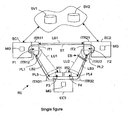
- the three switching elements ECl to EC3 ore interconnected by bidirectional optical links LBJ (j 1 to 3), the first switching element EC1 is connected to the third switching element EC3 by a unidirectional optional link LU1, and the second switching element EC2 is connected to the third switching element EC3 by a unidirectional optical link LU2.
- the first switching element EC1 comprises two bidirectional interfaces ITR11 and ITR12 for transmission and reception and a unidirectional interface IT1 for transmission
- the second switching element EC2 comprises two bidirectional interfaces ITR21 and ITR22 for transmission and reception and a unidirectional interface IT2 for transmission
- the third switching element EC3 comprises two bidirectional interfaces ITR31 and ITR32 for transmission and reception and two unidirectional interfaces IR1 and IR2 for reception.
- the bidirectional interfaces ITR11 and ITR21 are interconnected by the bidirectional optical link LB1.
- the bidirectional interfaces ITR12 and ITR31 are interconnected by the bidirectional optical link LB2.
- the bidirectional interfaces ITR22 and ITR32 are interconnected by the bidirectional optical link LB3.
- the transmission interface IT1 is connected to the reception interface IR1 by the unidirectional optical link LU1.
- the transmission interface IT2 is connected to the reception interface IR2 by the unidirectional optical link LU2.
- Each bidirectional interface of a switching element ECi is associated with a bidirectional physical port and each unidirectional interface of a switching element ECi is associated with a (number of) unidirectional physical port(s).
- the present example of an Internet network RE is for the protected transmission of video streams over a point-to-point connection to the third switching element EC3.
- the first switching element EC1 is by default that used to transmit video streams coming from a first video server SV1 and/or a second video server SV2 to the third switching element EC3, while the second switching element EC2 protects the first switching element EC1. if it fails or is undergoing maintenance or in the event of a transmission problem on the bidirectional optical link LB2 or the unidirectional optical link LU1.
- the second switching element EC2 is therefore also connected to the first video server and/or to a second video server SV2 in order to be able to transmit video streams to the third switching element EC3 if the first switching element EC1 is not able to do so.
- the invention is intended to enable the Ethernet protocols used to configure the Ethernet network RE, to be more precise the ports of its switching elements ECi, via its bidirectional optical links LBj, to take account of bidirectional physical ports and unidirectional physical ports of the switching elements of the Ethernet network RE.
- the expression “configuring a port” refers to placing it in an active (or passing or forwarding) state in which it allows the transmission and/or reception of data and a passive (or blocking or discarding) state in which it prohibits the transmission and/or reception of data.
- the invention applies provided that at least two switching elements of an Ethernet network are interconnected by at least first and second parallel optical links (of which at least the first is bidirectional) and each has at least one bidirectional physical port and at least one unidirectional physical port connected to the first and second parallel optical links, respectively.
- the Ethernet protocol used by the Ethernet network RE is the RSTP spanning tree network topology construction protocol.
- the invention is not limited to that type of Ethernet protocol. It relates to any type of Ethernet protocol based on the transmission of messages over bidirectional optical links and in particular to link aggregation protocols such as the LACP.
- the invention consists in using a configuration process including three main steps in an Ethernet network RE of the above type.
- the first step consists in defining a logical port PLk (k > 0) in each switching element ECi that is connected to another switching element ECi' by at least one bidirectional physical port connected to a bidirectional optical link LBj and by at least one unidirectional physical port connected to another optical link LU1 or LU2, where applicable a unidirectional link.
- each logical port PLk of a switching element ECi comprises each bidirectional physical port and each unidirectional physical port used to interconnect said switching element ECi with at least one other switching element ECi' (or groups them together under the same logical port number). Consequently, a logical port PLk comprises at least one bidirectional physical port and at least one unidirectional physical port. Furthermore, one or more (at least two) logical ports PLk may be defined in a switching element ECi; for example, a switching element ECi in which are defined at least two logical ports PLk may be connected to at least two other switching elements.
- the first switching element EC1 a logical port PL1 including the bidirectional physical port of the bidirectional interface ITR12 and the unidirectional physical port of the transmission interface IT1
- the second switching element EC2 a logical port PL2 including the bidirectional physical port of the bidirectional interface ITR22 and the unidirectional physical port of the transmission interface IT2
- the third switching element EC3 a first logical port PL3, including the bidirectional physical port of the bidirectional interface ITR31 and the unidirectional physical port of the receive interface IR1, and a second logical port PL4, including the bidirectional physical port of the bidirectional interface ITR32 and the unidirectional physical port of the receive interface IR2.
- the second step consists in using the Ethernet protocol (here RSTP) to define the respective states of the bidirectional physical ports (ITRi1 and ITRi2) of the various switching elements ECi. These states are defined in an entirely conventional manner by means of messages sent over the bidirectional optical links LBj. In the case of the RSTP, for example, the messages are called bridge protocol data units (BPDU).
- RSTP Ethernet protocol
- ITRi1 and ITRi2 the respective states of the bidirectional physical ports of the various switching elements ECi.
- BPDU bridge protocol data units
- each switching element ECi is associated with a bridge identifier, the switching element holding the identifier of the numerically lowest bridge constituting the root of the spanning tree ST. Each switching element ECi then determines the lowest cost path for accessing the root of its tree ST.
- the root is the first switching element EC1, so that the lowest cost path between the third switching element EC3 and the first switching element EC1 uses only the bidirectional optical link LB2 and the lowest cost path between the second switching element EC2 and the first switching element EC1 uses only the bidirectional optical link LB1.
- the tree ST therefore comprises a root EC1 connected to two branches terminating in the switching elements EC2 and EC3 and interconnected by another branch consisting of the bidirectional optical link LB3.
- Ethernet networks in more complex examples of Ethernet networks than that described above with reference to the single figure a plurality of trees may be defined and constructed, for example using variants of the RSTP or MSTP, and the data traffic may be restricted to certain tree branches using Ethernet virtual local area networks (VLAN).
- VLAN Ethernet virtual local area networks
- the switching element ECi Once the switching element ECi has determined the lowest cost path for accessing the root of its tree ST, it assigns the active state to each bidirectional physical port that is connected to the bidirectional optical link belonging to the lowest cost path and the passive state to each other bidirectional physical port.
- the first switching element EC1 places in the active state the two bidirectional physical ports that are respectively associated with its two bidirectional interfaces ITR11 and ITR12
- the second switching element EC2 places in the active state its bidirectional physical port that is associated with its bidirectional interface IDR21 and in the passive state its bidirectional physical port that is associated with its bidirectional interface ITR22
- the third switching element EC3 places in the active state its two bidirectional physical ports that are associated with its bidirectional interfaces ITR31 and ITR32. Placing the interface ITR22 facing ITR32 in the passive state prevents the creation of a loop.
- placing a port in the active (or forwarding) state consists in authorizing it to transmit and receive data traffic and to access the medium access control (MAC) addresses of the various sources of that data traffic stored in the MAC address table or in a filtering database of its switching element ECi, whereas placing a port in the passive (or discarding) state consists in prohibiting it from transmitting and receiving data traffic and accessing the MAC addresses of the various sources of that data traffic.
- MAC medium access control
- the third step consists in using each bidirectional physical port of each logical port to transmit Ethernet signaling messages representing its state and the state of each unidirectional physical port of said logical port.
- each unidirectional physical port that is part of a logical port PLk is placed in the same state as the bidirectional physical port that is part of the logical port PLk. This placement is preferably decided on and managed internally by each switching element ECi.
- the first switching element EC1 places in the active state its unidirectional physical port that is part of its logical port PL1 (arrow F1)
- the second switching element EC2 places in the passive state its unidirectional physical port that is part of its logical port PL2 (arrow F2)
- the third switching element EC3 places in the active state its first unidirectional physical port that is part of its first logical port PL3 (arrow F3) and in the active state its second unidirectional physical port that is part of its second logical port PL4 (arrow F4), even if the second logical port PL2 to which it is connected is in the passive state (on a blocked line, it is preferable if only one port is passive; here the arbitrary choice has been made to block a port on a hub (EC2) rather than on a DSLAM (EC3)).
- the third switching element EC3 therefore uses its third logical port PL3 to communicate with the first switching element EC1 and the second switching element EC2.
- the bidirectional and unidirectional physical ports included in the logical port PL1 being both placed in the active state the logical port PL1 is therefore considered to be placed in its active state.
- the bidirectional and unidirectional physical ports respectively included in the logical ports PL3, PL4 being both placed in the active state the logical ports PL3 and PL4 are therefore considered to be placed in the active state.
- the bidirectional and unidirectional physical ports included in the logical port PL2 being placed in the passive state the logical port PL2 is therefore considered to be placed in its passive state, so that no data can be transmitted or received by means of the bidirectional optical link LB3 and the unidirectional optical link LU2 (as indicated by the double line EB in the single figure).
- Each unidirectional physical port forming part of a logical port PLk can therefore use the Ethernet protocol (here RSTP) indirectly via the bidirectional physical port of its logical port PLk to define its state (active or passive).
- Ethernet protocol here RSTP
- Ethernet protocol here RSTP
- RSTP reconverges automatically in order to redefine the respective states of at least some of the other bidirectional physical ports of its switching element ECi, for example EC1, and of the other switching elements ECi' concerned, for example EC2 and EC3.
- This reconvergence is intended to enable data entering the switching element (EC1) to be transmitted to the destination switching element (EC3) via at least one other switching element (here EC2), and vice versa in the opposite direction.
- the first switching element EC1 places in the passive state its bidirectional physical port that is associated with its bidirectional interface ITR12 if a problem has arisen at the level of the bidirectional optical link LB2 connected to that interface, and maintains its bidirectional physical port that is associated with its other bidirectional interface ITR11 in the active state.
- the second switching element EC2 maintains its bidirectional physical port that is associated with its bidirectional interface ITR21 in the active state and places in the active state its bidirectional physical port that is associated with its bidirectional interface ITR22.
- the third switching element EC3 places in the passive state its bidirectional physical port that is associated with its bidirectional interface ITR31 and maintains its directional physical port that is associated with its bidirectional interface ITR32 in the active state.
- each switching element ECi has redefined the respective states of its bidirectional physical ports, each unidirectional physical port that is part of a logical port PLk including a bidirectional physical port that has been the subject of a change of state is placed in the same state as that bidirectional physical port. This placement is preferably decided on and managed internally by each switching element ECi.
- the first switching element EC1 places in the passive state its unidirectional physical port (IT1) that is part of its logical port PL1 if a problem has arisen at the level of the bidirectional optical link LB2 that is connected to the bidirectional interface ITR12.
- the second switching element EC2 places in the active state its unidirectional physical port (IT2) that is part of its logical port PL2.
- the third switching element EC3 places in the passive state its first unidirectional physical port (IR1) that is part of its logical port PL3.
- the bidirectional and unidirectional physical ports respectively included in the logical ports PL1 and PL3 being placed in the passive state the logical ports PL1 and PL3 are now considered to be placed in their passive state, so no data can be transmitted or received by means of the bidirectional optical link LB2 and no data can be transmitted by means of the unidirectional optical link LU1.
- the bidirectional physical port (ITR12) that is part of the logical port PL1 is placed in the passive state and, as indicated above, the Ethernet protocol, here RSTP, reconverges automatically in order to define the respective states of the bidirectional physical ports of the switching elements ECi that are not part of the logical ports PL1 and PL3.
- This reconvergence is intended to enable data reaching the switching element (EC1) to be transmitted to the destination switching element (EC3) via at least one other switching element (here EC2), and vice versa in the opposite direction.
- the second switching element EC2 maintains its bidirectional physical port that is associated with its bidirectional interface ITR21 in the active state and places in the active state its bidirectional physical port that is associated with its bidirectional interface ITR22 and the third switching element EC3 maintains its bidirectional physical port that is associated with its bidirectional interface ITR32 in the active state.
- the failure is detected through detection of a fault at the level of the unidirectional receive interface IR1 of the logical port PL3.
- the bidirectional physical port ITR31 that is part of the logical port PL3 of the third switching element EC3 is then placed in the passive state and, as indicated above, the Ethernet protocol, here RSTP, reconverges automatically.
- the logical ports initially in the active state may be placed in the active state by action at the level of the layer L2 of the switching elements concerned, here EC1 and EC3.
- the switching elements EC1 and EC3 may be prohibited from exchanging signaling traffic (or messages) or control traffic (or messages) (managed by xSTP), for example.
- the electrical power supply could be disconnected from all of the physical ports that are part of the logical ports PL1 and PL3, this action then being managed only by the layer L1.
- each unidirectional physical port forming part of a logical port PLk including a bidirectional physical port whose state has changed is placed in the same state as that bidirectional physical port. This placement is preferably decided on and managed internally by each switching element ECi.
- the second switching element EC2 places in the active state its unidirectional physical port that is part of its logical port PL2 and the third switching element EC3 maintains its unidirectional physical port that is part of its second logical port PL4 in the active state.
- the bidirectional and unidirectional physical ports included in the logical port PL2 now being placed in the active state the logical port PL2 is considered to be placed in its active state.
- the bidirectional and unidirectional physical ports respectively included in the logical ports PL3 and PL1 being placed in the passive state the logical ports PL1 and PL3 ore now considered to be placed in their passive state so that no data can be transmitted or received by means of the bidirectional optical link LB2 and no data can be transmitted by means of the unidirectional optical link LU1.
- the invention relates to any type of Ethernet protocol based on the transmission of messages over bidirectional optical links, and in particular link aggregation protocols such as the LACP, for example.
- link aggregation protocols such as the LACP, for example.
- LACP type link aggregation protocol is intended to group into bundles bidirectional physical ports that are connected to bidirectional links connecting pairs of switching elements.
- each connection between two switching elements must always be effected via at least one bidirectional optical link and at least one unidirectional optical link.
- certain optical links are shared, it is no longer obligatory for certain bidirectional optical links to depend systematically on a point-to-point bidirectional interface.
- the invention applies equally to situations in which the RSTP is replaced by other versions of the spanning tree protocol, for example the standard STP or MSTP version.
- the diagrammatic WPON included only one switching element (EC3, of the DSLAM type).
- the invention applies equally to situations in which the network includes a plurality of (at least two) switching elements like the element EC3.
- the network can still be governed by the RSTP, the use of the MSTP appears to be preferable at present, in particular with (bidirectional or unidirectional) physical links shared between a plurality of switching nodes such as the node EC3.
- the switching elements ECi of the Ethernet network RE have to be adapted in order to be able to use the method of the invention, to be more precise by adding to each of them a management module MG for defining each logical port PLk internally, as soon as at least one bidirectional physical port can be associated, in accordance with the invention, with at least one unidirectional physical port, for managing the use of an Ethernet protocol to define the state of each of its bidirectional physical ports, for analyzing the respective states of the bidirectional and unidirectional physical ports of its switching element ECi (which are associated within the logical port(s)) in order to transmit by means of each bidirectional physical port of each logical port Ethernet signaling messages representing its state and the state of each unidirectional physical port of this logical port
- Each management module MG may take the form of electronic circuits, software (or electronic data processing) modules, or a combination of circuits and software.
Landscapes
- Engineering & Computer Science (AREA)
- Computer Networks & Wireless Communication (AREA)
- Signal Processing (AREA)
- Small-Scale Networks (AREA)
- Use Of Switch Circuits For Exchanges And Methods Of Control Of Multiplex Exchanges (AREA)
Claims (14)
- Procédé de configuration de ports d'éléments de commutation dans un réseau Ethernet (RE) comprenant au moins deux éléments de commutation (ECi) connectés par au moins deux liaisons optiques, chaque élément de commutation disposant d'au moins un port physique bidirectionnel et d'au moins un port physique unidirectionnel, caractérisé en ce qu'il consiste i) à définir dans chacun des deux éléments de commutation (ECi) au moins un port logique (PLk) comprenant un port physique bidirectionnel et au moins un port physique unidirectionnel, de sorte que ledit port logique (PLk) soit perçu comme un port bidirectionnel par son élément de commutation (ECi), ii) à utiliser un protocole Ethernet adapté aux liaisons bidirectionnelles (LBj) pour définir des états respectifs desdits ports physiques bidirectionnels, et iii) à utiliser chaque port physique bidirectionnel de chaque port logique (PLk) pour transmettre des messages de signalisation d'Ethernet représentant son état et un état de chaque port physique unidirectionnel dudit port logique (PLk).
- Procédé selon la revendication 1, caractérisé en ce que tous les ports physiques d'un port logique (PLk) sont placés dans le même état, de sorte que chaque port physique unidirectionnel dudit port logique (PLk) soit pris en charge par ledit protocole Ethernet.
- Procédé selon la revendication 1, caractérisé en ce que, dans le cas d'une protection rapide des liaisons entre les premier et deuxième éléments de commutation (EC1) et (EC3) entre au moins une liaison bidirectionnelle (LB2) définie entre les ports physiques bidirectionnels de leurs ports logiques (PL1, PL3) et au moins une liaison unidirectionnelle (LU1) définie entre des ports physiques unidirectionnels respectivement dédiés à la transmission et à la réception dans les premier et deuxième éléments de commutation (EC1, EC3), et dans le cas d'une détection d'un problème entraînant le passage à l'état passif du port physique unidirectionnel de réception faisant partie dudit port logique (PL1), ledit deuxième élément de commutation (EC3) signale l'erreur audit premier élément de commutation (EC1) par l'intermédiaire de la liaison bidirectionnelle (LB2) et de leurs ports physiques bidirectionnels correspondants de sorte que ledit premier élément de commutation (EC1) déconnecte son port physique unidirectionnel de transmission connecté à la liaison unidirectionnelle (LU1) qui est affectée par le problème et transfère le trafic par le biais de la/des liaison(s) bidirectionnelle(s) et unidirectionnelle(s) qui est/sont toujours active(s).
- Procédé selon la revendication 1 ou 2, caractérisé en ce que, dans le cas d'un problème entraînant le passage d'un état actif à un état passif d'un port physique bidirectionnel faisant partie d'un premier port logique (PL1) d'un premier élément (EC1) connecté à un deuxième port logique (PL3) d'un deuxième élément (EC3), ledit protocole Ethernet est utilisé pour redéfinir lesdits états respectifs d'au moins certains des autres ports physiques bidirectionnels pour permettre la transmission de données entre lesdits premier et deuxième éléments (EC1, EC3) par l'intermédiaire d'au moins un troisième élément (EC2), après quoi chaque port physique unidirectionnel, qui fait partie d'un port logique (PLk) comprenant un port physique bidirectionnel dont l'état a changé, est placé dans le même état que celui du port physique bidirectionnel.
- Procédé selon l'une quelconque des revendications 1, 2 et 4, caractérisé en ce que, dans le cas d'un problème entraînant le passage d'un état actif à un état passif dans un port physique unidirectionnel faisant partie d'un premier port logique (PL1) d'un premier élément (EC1) connecté à un deuxième port logique (PL3) d'un deuxième élément (EC3) et en l'absence de liaisons de partage de charge de trafic qui sont toujours actives, le port physique bidirectionnel dudit premier port logique (PL1) est placé dans l'état passif, après quoi un protocole Ethernet de construction de topologie de réseau à arbre recouvrant est utilisé pour redéfinir les états respectifs d'au moins certains des autres ports physiques bidirectionnels pour permettre la transmission de données entre lesdits premier et deuxième éléments de commutation (EC1, EC3) par l'intermédiaire d'au moins un troisième élément de commutation (EC2), et chaque port physique unidirectionnel de chaque port logique (PLk) est placé dans le même état que celui du port physique bidirectionnel de ce port logique (PLk).
- Procédé selon l'une quelconque des revendications 1 à 5, caractérisé en ce que lesdits premier et deuxième ports logiques (PL1, PL3) sont placés dans l'état passif par une action au niveau de la couche physique desdits premier et deuxième éléments (EC1, EC3).
- Procédé selon la revendication 6, caractérisé en ce que le bloc d'alimentation électrique est retiré de tous les ports physiques faisant partie desdits premier et deuxième ports logiques (PL1, PL3).
- Procédé selon l'une quelconque des revendications 1 à 5, caractérisé en ce que lesdits premier et deuxième ports logiques (PL1, PL3) sont placés dans l'état passif par une action au niveau de la couche Ethernet desdits premier et deuxième éléments (EC1, EC3).
- Procédé selon la revendication 8, caractérisé en ce que ledit port logique (PL1, PL3) est forcé d'arrêter l'envoi de messages de signalisation de protocole Ethernet.
- Procédé selon l'une quelconque des revendications 1 à 9, caractérisé en ce que ledit protocole Ethernet est sélectionné parmi un groupe constitué d'au moins un protocole de construction de topologie de réseau à arbre recouvrant et un protocole d'agrégation de liaisons.
- Procédé selon la revendication 10, caractérisé en ce que ledit protocole de construction de topologie de réseau à arbre recouvrant est le RSTP ou le MSTP.
- Procédé selon la revendication 10, caractérisé en ce que ledit protocole d'agrégation de liaisons est le LACP.
- Élément de commutation (ECi) pour un réseau Ethernet (RE) comprenant au moins un port physique bidirectionnel connecté à au moins un port physique bidirectionnel d'un autre élément (ECi') par l'intermédiaire d'une première liaison optique (LB2) et au moins un port unidirectionnel connecté à au moins un port physique unidirectionnel dudit autre élément (ECi') par l'intermédiaire d'une deuxième liaison optique (LU1), caractérisé en ce qu'il comprend des moyens de gestion (MG) adaptés i) pour définir de manière interne au moins un port logique (PLk) comprenant chaque port physique bidirectionnel et chaque port physique unidirectionnel respectivement connectés auxdites première et deuxième liaisons optiques (LB1, LU1), de sorte que ledit port logique (PLk) soit perçu de manière interne comme un port bidirectionnel, ii) pour gérer l'utilisation d'un protocole Ethernet adapté aux liaisons bidirectionnelles (LBj) pour définir un état de chacun de ses ports physiques bidirectionnels, et iii) pour transmettre au moyen de chaque port physique bidirectionnel dudit port logique (PLk) des messages de signalisation d'Ethernet représentant son état et un état de chaque port physique unidirectionnel dudit port logique (PLk).
- Utilisation du procédé de configuration selon les revendications 1 à 12 et de l'élément de commutation (ECi) selon la revendication 13 pour configurer des connexions sélectionnées parmi un groupe constitué de connexions point à point et de connexions point à multipoint impliquant des liaisons optiques partagées.
Applications Claiming Priority (1)
| Application Number | Priority Date | Filing Date | Title |
|---|---|---|---|
| PCT/EP2005/014233 WO2007068282A1 (fr) | 2005-12-13 | 2005-12-13 | Procede de configuration, element de commutation et utilisation du procede de configuration en vue de configurer un reseau ethernet dote de liaisons optiques par defintion des ports logiques composes de ports pysiques bidirectionnels et unidirectionnels |
Publications (3)
| Publication Number | Publication Date |
|---|---|
| EP1964331A1 EP1964331A1 (fr) | 2008-09-03 |
| EP1964331B1 true EP1964331B1 (fr) | 2010-08-18 |
| EP1964331B8 EP1964331B8 (fr) | 2011-03-23 |
Family
ID=36516349
Family Applications (1)
| Application Number | Title | Priority Date | Filing Date |
|---|---|---|---|
| EP05850404A Expired - Lifetime EP1964331B8 (fr) | 2005-12-13 | 2005-12-13 | Procédé de configuration, element de commutation et utilisation du procédé de configuration en vue de configurer un réseau ethernet dote de liaisons optiques en definissant des ports logiques composés de ports physiques bidirectionnels et unidirectionnels |
Country Status (4)
| Country | Link |
|---|---|
| EP (1) | EP1964331B8 (fr) |
| AT (1) | ATE478499T1 (fr) |
| DE (1) | DE602005023078D1 (fr) |
| WO (1) | WO2007068282A1 (fr) |
-
2005
- 2005-12-13 WO PCT/EP2005/014233 patent/WO2007068282A1/fr not_active Ceased
- 2005-12-13 AT AT05850404T patent/ATE478499T1/de not_active IP Right Cessation
- 2005-12-13 EP EP05850404A patent/EP1964331B8/fr not_active Expired - Lifetime
- 2005-12-13 DE DE602005023078T patent/DE602005023078D1/de not_active Expired - Lifetime
Also Published As
| Publication number | Publication date |
|---|---|
| DE602005023078D1 (de) | 2010-09-30 |
| WO2007068282A1 (fr) | 2007-06-21 |
| EP1964331B8 (fr) | 2011-03-23 |
| EP1964331A1 (fr) | 2008-09-03 |
| ATE478499T1 (de) | 2010-09-15 |
Similar Documents
| Publication | Publication Date | Title |
|---|---|---|
| US8854982B2 (en) | Method and apparatus for managing the interconnection between network domains | |
| RU2530338C2 (ru) | Предварительно подготовленное сопряжение на основе состояния линий связи поставщиков (plsb) с маршрутизируемым резервированием | |
| US9385942B2 (en) | Methods, systems, and computer readable media for providing N-node multi-switch link aggregation groups (MLAGs) | |
| EP2104994B1 (fr) | Multi-hébergement à base de hachage | |
| US7643409B2 (en) | Computer network with point-to-point pseudowire redundancy | |
| US7177946B1 (en) | Optimal sync for rapid spanning tree protocol | |
| US8305938B2 (en) | Interworking an ethernet ring network with a spanning tree controlled ethernet network | |
| JP4778062B2 (ja) | プロバイダ・リンク状態ブリッジング | |
| US8730963B1 (en) | Methods, systems, and computer readable media for improved multi-switch link aggregation group (MLAG) convergence | |
| US8711863B2 (en) | Virtual links in a routed ethernet mesh network | |
| US7460492B2 (en) | Spanning tree loop guard | |
| CN101960798B (zh) | 多机箱端口信道上的分布式生成树协议 | |
| US8462668B2 (en) | System and method for implementation of layer 2 redundancy protocols across multiple networks | |
| EP1974485B1 (fr) | Protection contre les défaillances des services de réseaux locaux privés virtuels dans des réseaux en anneaux | |
| CN102449962B (zh) | 混合层2网络中的瞬态环路预防 | |
| US8638807B2 (en) | Method for managing ethernet ring network of VLAN-based bridge | |
| US8724519B2 (en) | Technique for dual homing interconnection between communication networks | |
| US20090168647A1 (en) | Interworking an Ethernet Ring Network and an Ethernet Network with Traffic Engineered Trunks | |
| CN101517966B (zh) | 用于检测混合交换网络中的传输泄漏的方法 | |
| CN101120548A (zh) | 在通信网络中操作节点的方法 | |
| US7502376B2 (en) | Layer-2 network with virtual private LAN service | |
| WO2012162946A1 (fr) | Procédé et système de traitement de message | |
| CN101567892B (zh) | 一种实现mstp多进程的方法及装置 | |
| EP1964331B1 (fr) | Procédé de configuration, element de commutation et utilisation du procédé de configuration en vue de configurer un réseau ethernet dote de liaisons optiques en definissant des ports logiques composés de ports physiques bidirectionnels et unidirectionnels | |
| Sharma et al. | Meshed tree protocol for faster convergence in switched networks |
Legal Events
| Date | Code | Title | Description |
|---|---|---|---|
| PUAI | Public reference made under article 153(3) epc to a published international application that has entered the european phase |
Free format text: ORIGINAL CODE: 0009012 |
|
| 17P | Request for examination filed |
Effective date: 20080714 |
|
| AK | Designated contracting states |
Kind code of ref document: A1 Designated state(s): AT BE BG CH CY CZ DE DK EE ES FI FR GB GR HU IE IS IT LI LT LU LV MC NL PL PT RO SE SI SK TR |
|
| 17Q | First examination report despatched |
Effective date: 20080925 |
|
| GRAP | Despatch of communication of intention to grant a patent |
Free format text: ORIGINAL CODE: EPIDOSNIGR1 |
|
| RTI1 | Title (correction) |
Free format text: CONFIGURATION METHOD, SWITCHING ELEMENT AND USE OF CONFIGURATION METHOD FOR CONFIGURING AN ETHERNET NETWORK WITH OPTICAL LINKS BY DEFINING LOGICAL PORTS MADE UP OF BIDIRECTIONAL |
|
| GRAS | Grant fee paid |
Free format text: ORIGINAL CODE: EPIDOSNIGR3 |
|
| GRAA | (expected) grant |
Free format text: ORIGINAL CODE: 0009210 |
|
| AK | Designated contracting states |
Kind code of ref document: B1 Designated state(s): AT BE BG CH CY CZ DE DK EE ES FI FR GB GR HU IE IS IT LI LT LU LV MC NL PL PT RO SE SI SK TR |
|
| REG | Reference to a national code |
Ref country code: GB Ref legal event code: FG4D |
|
| REG | Reference to a national code |
Ref country code: CH Ref legal event code: EP |
|
| REG | Reference to a national code |
Ref country code: IE Ref legal event code: FG4D |
|
| REF | Corresponds to: |
Ref document number: 602005023078 Country of ref document: DE Date of ref document: 20100930 Kind code of ref document: P |
|
| REG | Reference to a national code |
Ref country code: NL Ref legal event code: VDEP Effective date: 20100818 |
|
| RAP4 | Party data changed (patent owner data changed or rights of a patent transferred) |
Owner name: ALCATEL LUCENT Owner name: GE, AN Owner name: ROUYER, JESSY VICTOR |
|
| LTIE | Lt: invalidation of european patent or patent extension |
Effective date: 20100818 |
|
| PG25 | Lapsed in a contracting state [announced via postgrant information from national office to epo] |
Ref country code: LT Free format text: LAPSE BECAUSE OF FAILURE TO SUBMIT A TRANSLATION OF THE DESCRIPTION OR TO PAY THE FEE WITHIN THE PRESCRIBED TIME-LIMIT Effective date: 20100818 Ref country code: FI Free format text: LAPSE BECAUSE OF FAILURE TO SUBMIT A TRANSLATION OF THE DESCRIPTION OR TO PAY THE FEE WITHIN THE PRESCRIBED TIME-LIMIT Effective date: 20100818 Ref country code: AT Free format text: LAPSE BECAUSE OF FAILURE TO SUBMIT A TRANSLATION OF THE DESCRIPTION OR TO PAY THE FEE WITHIN THE PRESCRIBED TIME-LIMIT Effective date: 20100818 |
|
| RAP2 | Party data changed (patent owner data changed or rights of a patent transferred) |
Owner name: ALCATEL LUCENT |
|
| PG25 | Lapsed in a contracting state [announced via postgrant information from national office to epo] |
Ref country code: PT Free format text: LAPSE BECAUSE OF FAILURE TO SUBMIT A TRANSLATION OF THE DESCRIPTION OR TO PAY THE FEE WITHIN THE PRESCRIBED TIME-LIMIT Effective date: 20101220 Ref country code: PL Free format text: LAPSE BECAUSE OF FAILURE TO SUBMIT A TRANSLATION OF THE DESCRIPTION OR TO PAY THE FEE WITHIN THE PRESCRIBED TIME-LIMIT Effective date: 20100818 Ref country code: BG Free format text: LAPSE BECAUSE OF FAILURE TO SUBMIT A TRANSLATION OF THE DESCRIPTION OR TO PAY THE FEE WITHIN THE PRESCRIBED TIME-LIMIT Effective date: 20101118 Ref country code: CY Free format text: LAPSE BECAUSE OF FAILURE TO SUBMIT A TRANSLATION OF THE DESCRIPTION OR TO PAY THE FEE WITHIN THE PRESCRIBED TIME-LIMIT Effective date: 20100818 Ref country code: IS Free format text: LAPSE BECAUSE OF FAILURE TO SUBMIT A TRANSLATION OF THE DESCRIPTION OR TO PAY THE FEE WITHIN THE PRESCRIBED TIME-LIMIT Effective date: 20101218 Ref country code: SI Free format text: LAPSE BECAUSE OF FAILURE TO SUBMIT A TRANSLATION OF THE DESCRIPTION OR TO PAY THE FEE WITHIN THE PRESCRIBED TIME-LIMIT Effective date: 20100818 |
|
| PG25 | Lapsed in a contracting state [announced via postgrant information from national office to epo] |
Ref country code: NL Free format text: LAPSE BECAUSE OF FAILURE TO SUBMIT A TRANSLATION OF THE DESCRIPTION OR TO PAY THE FEE WITHIN THE PRESCRIBED TIME-LIMIT Effective date: 20100818 Ref country code: SE Free format text: LAPSE BECAUSE OF FAILURE TO SUBMIT A TRANSLATION OF THE DESCRIPTION OR TO PAY THE FEE WITHIN THE PRESCRIBED TIME-LIMIT Effective date: 20100818 Ref country code: GR Free format text: LAPSE BECAUSE OF FAILURE TO SUBMIT A TRANSLATION OF THE DESCRIPTION OR TO PAY THE FEE WITHIN THE PRESCRIBED TIME-LIMIT Effective date: 20101119 Ref country code: BE Free format text: LAPSE BECAUSE OF FAILURE TO SUBMIT A TRANSLATION OF THE DESCRIPTION OR TO PAY THE FEE WITHIN THE PRESCRIBED TIME-LIMIT Effective date: 20100818 Ref country code: LV Free format text: LAPSE BECAUSE OF FAILURE TO SUBMIT A TRANSLATION OF THE DESCRIPTION OR TO PAY THE FEE WITHIN THE PRESCRIBED TIME-LIMIT Effective date: 20100818 |
|
| PG25 | Lapsed in a contracting state [announced via postgrant information from national office to epo] |
Ref country code: DK Free format text: LAPSE BECAUSE OF FAILURE TO SUBMIT A TRANSLATION OF THE DESCRIPTION OR TO PAY THE FEE WITHIN THE PRESCRIBED TIME-LIMIT Effective date: 20100818 |
|
| REG | Reference to a national code |
Ref country code: DE Ref legal event code: R081 Ref document number: 602005023078 Country of ref document: DE Owner name: ALCATEL LUCENT, FR Free format text: FORMER OWNER: ALCATEL LUCENT,ANDREW GE,JESSY VICTOR ROUYER, , US Effective date: 20110223 Ref country code: DE Ref legal event code: R081 Ref document number: 602005023078 Country of ref document: DE Owner name: ALCATEL LUCENT, FR Free format text: FORMER OWNERS: ALCATEL LUCENT, PARIS, FR; GE, ANDREW, PLANO, TEX., US; ROUYER, JESSY VICTOR, FORT WORTH, TEX., US Effective date: 20110223 |
|
| PG25 | Lapsed in a contracting state [announced via postgrant information from national office to epo] |
Ref country code: SK Free format text: LAPSE BECAUSE OF FAILURE TO SUBMIT A TRANSLATION OF THE DESCRIPTION OR TO PAY THE FEE WITHIN THE PRESCRIBED TIME-LIMIT Effective date: 20100818 Ref country code: EE Free format text: LAPSE BECAUSE OF FAILURE TO SUBMIT A TRANSLATION OF THE DESCRIPTION OR TO PAY THE FEE WITHIN THE PRESCRIBED TIME-LIMIT Effective date: 20100818 Ref country code: CZ Free format text: LAPSE BECAUSE OF FAILURE TO SUBMIT A TRANSLATION OF THE DESCRIPTION OR TO PAY THE FEE WITHIN THE PRESCRIBED TIME-LIMIT Effective date: 20100818 Ref country code: IT Free format text: LAPSE BECAUSE OF FAILURE TO SUBMIT A TRANSLATION OF THE DESCRIPTION OR TO PAY THE FEE WITHIN THE PRESCRIBED TIME-LIMIT Effective date: 20100818 Ref country code: RO Free format text: LAPSE BECAUSE OF FAILURE TO SUBMIT A TRANSLATION OF THE DESCRIPTION OR TO PAY THE FEE WITHIN THE PRESCRIBED TIME-LIMIT Effective date: 20100818 |
|
| PLBE | No opposition filed within time limit |
Free format text: ORIGINAL CODE: 0009261 |
|
| STAA | Information on the status of an ep patent application or granted ep patent |
Free format text: STATUS: NO OPPOSITION FILED WITHIN TIME LIMIT |
|
| PG25 | Lapsed in a contracting state [announced via postgrant information from national office to epo] |
Ref country code: ES Free format text: LAPSE BECAUSE OF FAILURE TO SUBMIT A TRANSLATION OF THE DESCRIPTION OR TO PAY THE FEE WITHIN THE PRESCRIBED TIME-LIMIT Effective date: 20101129 |
|
| 26N | No opposition filed |
Effective date: 20110519 |
|
| PG25 | Lapsed in a contracting state [announced via postgrant information from national office to epo] |
Ref country code: MC Free format text: LAPSE BECAUSE OF NON-PAYMENT OF DUE FEES Effective date: 20101231 |
|
| REG | Reference to a national code |
Ref country code: CH Ref legal event code: PL |
|
| REG | Reference to a national code |
Ref country code: DE Ref legal event code: R097 Ref document number: 602005023078 Country of ref document: DE Effective date: 20110519 |
|
| PG25 | Lapsed in a contracting state [announced via postgrant information from national office to epo] |
Ref country code: CH Free format text: LAPSE BECAUSE OF NON-PAYMENT OF DUE FEES Effective date: 20101231 Ref country code: LI Free format text: LAPSE BECAUSE OF NON-PAYMENT OF DUE FEES Effective date: 20101231 Ref country code: IE Free format text: LAPSE BECAUSE OF NON-PAYMENT OF DUE FEES Effective date: 20101213 |
|
| PG25 | Lapsed in a contracting state [announced via postgrant information from national office to epo] |
Ref country code: LU Free format text: LAPSE BECAUSE OF NON-PAYMENT OF DUE FEES Effective date: 20101213 Ref country code: HU Free format text: LAPSE BECAUSE OF FAILURE TO SUBMIT A TRANSLATION OF THE DESCRIPTION OR TO PAY THE FEE WITHIN THE PRESCRIBED TIME-LIMIT Effective date: 20110219 |
|
| PG25 | Lapsed in a contracting state [announced via postgrant information from national office to epo] |
Ref country code: TR Free format text: LAPSE BECAUSE OF FAILURE TO SUBMIT A TRANSLATION OF THE DESCRIPTION OR TO PAY THE FEE WITHIN THE PRESCRIBED TIME-LIMIT Effective date: 20100818 |
|
| REG | Reference to a national code |
Ref country code: FR Ref legal event code: GC Effective date: 20131018 |
|
| REG | Reference to a national code |
Ref country code: FR Ref legal event code: RG Effective date: 20141016 |
|
| REG | Reference to a national code |
Ref country code: FR Ref legal event code: CA Effective date: 20150521 |
|
| REG | Reference to a national code |
Ref country code: FR Ref legal event code: CA Effective date: 20150521 |
|
| REG | Reference to a national code |
Ref country code: FR Ref legal event code: PLFP Year of fee payment: 11 |
|
| REG | Reference to a national code |
Ref country code: FR Ref legal event code: PLFP Year of fee payment: 12 |
|
| PGFP | Annual fee paid to national office [announced via postgrant information from national office to epo] |
Ref country code: FR Payment date: 20161222 Year of fee payment: 12 |
|
| PGFP | Annual fee paid to national office [announced via postgrant information from national office to epo] |
Ref country code: DE Payment date: 20171211 Year of fee payment: 13 |
|
| PGFP | Annual fee paid to national office [announced via postgrant information from national office to epo] |
Ref country code: GB Payment date: 20171221 Year of fee payment: 13 |
|
| REG | Reference to a national code |
Ref country code: FR Ref legal event code: ST Effective date: 20180831 |
|
| PG25 | Lapsed in a contracting state [announced via postgrant information from national office to epo] |
Ref country code: FR Free format text: LAPSE BECAUSE OF NON-PAYMENT OF DUE FEES Effective date: 20180102 |
|
| REG | Reference to a national code |
Ref country code: GB Ref legal event code: 732E Free format text: REGISTERED BETWEEN 20190429 AND 20190502 |
|
| REG | Reference to a national code |
Ref country code: DE Ref legal event code: R082 Ref document number: 602005023078 Country of ref document: DE Representative=s name: MENZIETTI WETZEL, DE Ref country code: DE Ref legal event code: R081 Ref document number: 602005023078 Country of ref document: DE Owner name: PROVENANCE ASSET GROUP LLC, PITTSFORD, US Free format text: FORMER OWNER: ALCATEL LUCENT, PARIS, FR |
|
| REG | Reference to a national code |
Ref country code: DE Ref legal event code: R119 Ref document number: 602005023078 Country of ref document: DE |
|
| GBPC | Gb: european patent ceased through non-payment of renewal fee |
Effective date: 20181213 |
|
| PG25 | Lapsed in a contracting state [announced via postgrant information from national office to epo] |
Ref country code: DE Free format text: LAPSE BECAUSE OF NON-PAYMENT OF DUE FEES Effective date: 20190702 |
|
| PG25 | Lapsed in a contracting state [announced via postgrant information from national office to epo] |
Ref country code: GB Free format text: LAPSE BECAUSE OF NON-PAYMENT OF DUE FEES Effective date: 20181213 |