EP1963942B1 - Autonomous and automatic landing system for drones - Google Patents
Autonomous and automatic landing system for drones Download PDFInfo
- Publication number
- EP1963942B1 EP1963942B1 EP06819896A EP06819896A EP1963942B1 EP 1963942 B1 EP1963942 B1 EP 1963942B1 EP 06819896 A EP06819896 A EP 06819896A EP 06819896 A EP06819896 A EP 06819896A EP 1963942 B1 EP1963942 B1 EP 1963942B1
- Authority
- EP
- European Patent Office
- Prior art keywords
- aircraft
- beacon
- localisation
- detection
- radar
- Prior art date
- Legal status (The legal status is an assumption and is not a legal conclusion. Google has not performed a legal analysis and makes no representation as to the accuracy of the status listed.)
- Active
Links
- 238000005259 measurement Methods 0.000 claims description 47
- 238000001514 detection method Methods 0.000 claims description 39
- 230000004807 localization Effects 0.000 claims description 35
- 238000001914 filtration Methods 0.000 claims description 3
- 238000012163 sequencing technique Methods 0.000 description 14
- 238000013459 approach Methods 0.000 description 9
- 238000004891 communication Methods 0.000 description 8
- 238000002592 echocardiography Methods 0.000 description 7
- 238000012937 correction Methods 0.000 description 6
- 230000005540 biological transmission Effects 0.000 description 5
- 238000012545 processing Methods 0.000 description 4
- 230000005855 radiation Effects 0.000 description 3
- 230000002457 bidirectional effect Effects 0.000 description 2
- 230000000295 complement effect Effects 0.000 description 2
- 230000001419 dependent effect Effects 0.000 description 2
- 230000010354 integration Effects 0.000 description 2
- 238000011160 research Methods 0.000 description 2
- 230000008878 coupling Effects 0.000 description 1
- 238000010168 coupling process Methods 0.000 description 1
- 238000005859 coupling reaction Methods 0.000 description 1
- 230000001934 delay Effects 0.000 description 1
- 238000013461 design Methods 0.000 description 1
- 239000006185 dispersion Substances 0.000 description 1
- 238000005516 engineering process Methods 0.000 description 1
- 238000009434 installation Methods 0.000 description 1
- 238000012544 monitoring process Methods 0.000 description 1
- 238000011084 recovery Methods 0.000 description 1
- 230000001360 synchronised effect Effects 0.000 description 1
Images


Classifications
-
- G—PHYSICS
- G01—MEASURING; TESTING
- G01S—RADIO DIRECTION-FINDING; RADIO NAVIGATION; DETERMINING DISTANCE OR VELOCITY BY USE OF RADIO WAVES; LOCATING OR PRESENCE-DETECTING BY USE OF THE REFLECTION OR RERADIATION OF RADIO WAVES; ANALOGOUS ARRANGEMENTS USING OTHER WAVES
- G01S13/00—Systems using the reflection or reradiation of radio waves, e.g. radar systems; Analogous systems using reflection or reradiation of waves whose nature or wavelength is irrelevant or unspecified
- G01S13/74—Systems using reradiation of radio waves, e.g. secondary radar systems; Analogous systems
- G01S13/82—Systems using reradiation of radio waves, e.g. secondary radar systems; Analogous systems wherein continuous-type signals are transmitted
- G01S13/825—Systems using reradiation of radio waves, e.g. secondary radar systems; Analogous systems wherein continuous-type signals are transmitted with exchange of information between interrogator and responder
-
- G—PHYSICS
- G01—MEASURING; TESTING
- G01S—RADIO DIRECTION-FINDING; RADIO NAVIGATION; DETERMINING DISTANCE OR VELOCITY BY USE OF RADIO WAVES; LOCATING OR PRESENCE-DETECTING BY USE OF THE REFLECTION OR RERADIATION OF RADIO WAVES; ANALOGOUS ARRANGEMENTS USING OTHER WAVES
- G01S11/00—Systems for determining distance or velocity not using reflection or reradiation
- G01S11/02—Systems for determining distance or velocity not using reflection or reradiation using radio waves
- G01S11/10—Systems for determining distance or velocity not using reflection or reradiation using radio waves using Doppler effect
-
- G—PHYSICS
- G01—MEASURING; TESTING
- G01S—RADIO DIRECTION-FINDING; RADIO NAVIGATION; DETERMINING DISTANCE OR VELOCITY BY USE OF RADIO WAVES; LOCATING OR PRESENCE-DETECTING BY USE OF THE REFLECTION OR RERADIATION OF RADIO WAVES; ANALOGOUS ARRANGEMENTS USING OTHER WAVES
- G01S13/00—Systems using the reflection or reradiation of radio waves, e.g. radar systems; Analogous systems using reflection or reradiation of waves whose nature or wavelength is irrelevant or unspecified
- G01S13/003—Bistatic radar systems; Multistatic radar systems
-
- G—PHYSICS
- G01—MEASURING; TESTING
- G01S—RADIO DIRECTION-FINDING; RADIO NAVIGATION; DETERMINING DISTANCE OR VELOCITY BY USE OF RADIO WAVES; LOCATING OR PRESENCE-DETECTING BY USE OF THE REFLECTION OR RERADIATION OF RADIO WAVES; ANALOGOUS ARRANGEMENTS USING OTHER WAVES
- G01S13/00—Systems using the reflection or reradiation of radio waves, e.g. radar systems; Analogous systems using reflection or reradiation of waves whose nature or wavelength is irrelevant or unspecified
- G01S13/88—Radar or analogous systems specially adapted for specific applications
- G01S13/91—Radar or analogous systems specially adapted for specific applications for traffic control
- G01S13/913—Radar or analogous systems specially adapted for specific applications for traffic control for landing purposes
-
- G—PHYSICS
- G05—CONTROLLING; REGULATING
- G05D—SYSTEMS FOR CONTROLLING OR REGULATING NON-ELECTRIC VARIABLES
- G05D1/00—Control of position, course or altitude of land, water, air, or space vehicles, e.g. automatic pilot
- G05D1/04—Control of altitude or depth
- G05D1/06—Rate of change of altitude or depth
- G05D1/0607—Rate of change of altitude or depth specially adapted for aircraft
- G05D1/0653—Rate of change of altitude or depth specially adapted for aircraft during a phase of take-off or landing
- G05D1/0676—Rate of change of altitude or depth specially adapted for aircraft during a phase of take-off or landing specially adapted for landing
Definitions
- the present invention relates to the field of aircraft and in particular the field of autonomous and automatic aircraft such as drones. It relates more particularly to the guidance of these aircraft in approach and landing phase.
- GPS-based systems or Differential GPS which offer the advantage of being inexpensive to implement.
- this solution poses the problem of the availability or the continuity of GPS service in high precision mode.
- the vulnerability of GPS systems in the presence of jammers is well known
- Another way is to use laser-based telemetry and guidance systems which have the advantage of not requiring a large implementation logistics, but whose use has the disadvantage of being dependent on the weather conditions. and whose implementation requires the passage of a research phase ("scanning") of the object to be guided, because of the narrowness of the brush emitted.
- a complementary positioning equipment in absolute relative to the track is necessary.
- Another means which is still similar in principle to the preceding means, is to use a radar tracking or tracking system, which is very directional, operating for example in millimetric band.
- This type of system is however sophisticated and therefore expensive.
- they like the laser telemetry systems, they also require a research phase for the designation of objectives and an absolute positioning with respect to the track. They are also sensitive to both the climatic conditions and the conformation of the terrain which constitutes the approach zone of the ground on which the guided object must be placed. In particular, in the case where it is desired to guide several aircraft, it is necessary to time-sharing and target-to-target rallies at the risk of losing a target and having to make a complete acquisition of the context. Finally, in the approach phase, the guiding constraints to keep the target in the radar beam are very important.
- the patent document published under the reference DE 196 20 682 A1 describes a transponder device for calibrating the measurements made by an electromagnetic detection device, a SAR-type radar system, embarked on an aircraft, the transponder being disposed on the ground and retransmitting to the radar a characteristic signal derived from the signal issued. According to this document, the signal transmitted by the transponder enables the on-board SAR radar to improve the accuracy of the measurements made.
- the system according to the invention further comprises a second radio beacon placed on the ground at the point of contact of the aircraft with the ground to enable the detection and localization device to perform measurements. differentials in the distance and angular position of the aircraft.
- the ground beacon comprises passive means enabling the detection and localization device to differentiate the echo reflected by this beacon with a fixed echo.
- these passive means are constituted by the blades of a moving fan.
- the first multifunction beacon embarked on board the aircraft, also comprises means for making altitude measurements, said beacon fulfilling the function of radio altimeter, the transmitting beacon periodically to the device for detecting and locating information relating to the altitude of the aircraft, the altitude measured by said beacon, the detection and location device exploiting the altitude information transmitted by the beacon to improve the accuracy of the measurement of the angular position of the aircraft.
- the operation of the detection and localization device alternates periods of localization active, duration ⁇ T1, during which it measures the distance and the angular position of the aircraft from the echo reflected by said aircraft and listening periods and data exchange, duration ⁇ T2, during which it measures the angular position of the aircraft from the signal transmitted by the beacon, and during which it transmits positioning information to the aircraft.
- the detection and localization device exploits the signals received during the N active positioning periods forming a same group to perform a doppler filtering of the signal, the filtered signal being used. for measuring the distance and the angular position of the aircraft, this measurement being used together with the angular position measurement obtained from the signal transmitted by the beacon during the listening and exchange period of the aircraft. data preceding said group, and with the altitude measurement transmitted by the beacon during this same period.
- the system comprises a third multifunction radio beacon, identical to the first beacon and embarked with the first beacon on each guided aircraft, and means making it possible to use each beacon alternately to perform the tasks. exchanging information with the detection and location device, as well as the task of producing a point source of emission, while the other beacon makes altitude measurements.
- the operation of the detection and localization device alternates groups of N active positioning periods, of duration ⁇ T1, during which it measures the distance and the angular position of the aircraft from the echo reflected by said aircraft, and listening and data exchange periods, duration ⁇ T2, during which it measures the angular position of the aircraft from the signal transmitted by one of the radio beacons multifunction. During these periods of duration ⁇ T 2 it also transmits positioning information to the aircraft via said beacon. Each group of active locating periods is then separated from the next group by a period of listening and data exchange.
- the task of exchanging information with the detection and localization device, as well as the task of producing a point source of emission, is carried out alternately, from a period of listening and data exchange to the other, by the first and the second beacon.
- the proposed device advantageously has a greater robustness with respect to geographical and climatic conditions than existing devices. It also has the advantage of being simpler design and therefore less expensive. It also advantageously has the ability to simultaneously guide several aircraft to the landing zone.
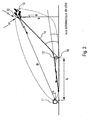
- the system mainly comprises a detection and location device 11, located on the ground, and a multifunction beacon 12 on board the aircraft 13.
- the main function of the detection device 11 is to periodically measure the altitude h of the aircraft 13 as well as the radial distance D which separates the aircraft from the point on which it is located. It also measures the differences in direction and altitude existing between the direction joining this device to the aircraft and a reference direction, preferably parallel to the axis of the runway on which the aircraft is supposed to land. To do this, uses, for example, angular deviation measurements, known elsewhere, allowing it to determine the azimuth and elevation relative to the guided aircraft.
- This device can for example, in a particular embodiment, be constituted in a relatively simple manner by a landing radar constituted by a conventional standby radar equipped with means for making angular deviation measurements and fixedly pointed in a given direction which corresponds globally to the optimal approach direction of the runway.
- this landing radar has a radiation pattern large enough to intercept one or more aircraft on approach without having to carry out a search operation.
- the detection device 11 may also consist of a radar equipped with an active antenna making it possible to form a plurality of reception beams in selected directions.
- Such a device can advantageously be used in particular when the operation of the system is potentially disturbed by multiple reflections radar echoes on the ground and on low-rise elements, buildings or vehicles, for example, placed on the ground.
- the position of the aircraft is determined by the radar by implementing calculations of telemetry and angular deviation, known elsewhere and not developed here.
- the integration over time of the successive positions of the aircraft allows the radar to determine its trajectory of the latter. This trajectory is compared by the radar computer to the trajectory allowing the aircraft to reach its landing point.
- the computer determines in particular for each measurement the difference ⁇ p between the existing actual position of the aircraft at the instant of the measurement and the position where the same aircraft would fall following the rejoining path.
- the homing path is symbolized by the dashed curve 14 whose projections are represented on the Figures 1 to 3 .
- the multifunction beacon 14 embarked by the aircraft, performs both autonomous measurement functions and answering beacon functions, as well as communication functions.
- the radar 11 and the beacon 12 form the basic elements of the system according to the invention.
- the multifunction beacon 12 also provides the radio altimeter complementary function.
- the on-board beacon comprises a transceiver as well as a computer intended in particular for processing the received signals.
- the beacon 12 also includes an antenna positioned under the aircraft and directed towards the ground.
- the altitude measurement is carried out, in known manner, by measuring the travel time of a wave emitted and reflected by the ground. According to the invention, the measurement results are transmitted to the radar which uses them if necessary to correct the altitude of the aircraft 13 determined using the radar echo.
- the altitude information provided by the beacon 12 is more particularly used from the moment the aircraft is at a distance relatively close to the landing point because in this phase the accuracy on the altitude measurement becomes important.
- the multifunction beacon 12 acts as a point source emitting towards the front of the aircraft 13 a signal whose level is substantially greater than the level of the reflected echo of the skin. by the aircraft 13.
- the aircraft 13 has an antenna, positioned at the front of the aircraft along the center line and directed forward.
- the radiation pattern of this antenna is in the form of a narrow brush so that the signal thus emitted is detected by the radar as coming from a point source and can be used by the radar 11 to determine accurately the angular position of the aircraft 13 with a better accuracy than that obtained from the reflected skin echo.
- the echo of skin can indeed come from various flickering parts of the fuselage of the aircraft, these glittering elements of the fuselage being placed at a greater or lesser distance from the median axis 31 of the aircraft. This may for example be the edges of the wings.
- the bias induced by the dispersion of the scintillating points on the fuselage is translated in practice by an error on the measurement of angular position (angles ⁇ and ⁇ ) of the aircraft 13 by the radar 11.
- this error can advantageously be corrected by comparing the angular position determined from the radar echo and the angular position determined from the signal transmitted by the beacon 12.
- the transmitted signal may advantageously consist of a single frequency CW signal, f 0 unique, transmitted continuously on a frequency located outside the band used for the radar location.
- the beacon 16 is then a simple device continuously transmitting a signal at a frequency
- the measurements of the successive positions of the aircraft over time, carried out by the radar 11, enable it to develop correction information intended for the aircraft 13.
- This information is used by the latter to correct its trajectory step by step, until reaching the landing path 14.
- the information, or orders, correction are transmitted to the aircraft through the communication channel that has the multifunction tag 12.
- This communication channel is a bidirectional channel which also allows the aircraft 13 to communicate its altitude to the radar 11. It also enables the aircraft to communicate with an operational center in relation to the radar and to send it various information, eg data collected during the mission. Finally, it makes it possible to transmit to the radar 11 various information relating to the identification of the aircraft 13 and the proper functioning of the equipment on board.
- the system according to the invention may also comprise a second fixed multifunctional beacon 15 positioned on the ground along the landing strip opposite the contact point 16 of the aircraft with the ground. Successive determinations of the position of the aircraft 13 with respect to this point 14 can thus be made differentially from the measurements of the distance of the aircraft 13 and the distance of the ground beacon 15 made by the radar. 11, and thus be free of bias.
- this beacon advantageously comprises means allowing it to retrodiffage towards the radar an echo whose frequency has a Doppler shift.
- these means consist of a movable reflector constituted for example by a moving fan.
- This particular embodiment is particularly advantageous because the ground beacon remains a simple passive device with regard to radar detection.
- any other solution for producing a synchronous signal of the signal transmitted by the radar and having a Doppler shift, is of course conceivable although more complex to implement.
- the second multifunction beacon 15 placed on the ground and intended to increase the accuracy of the distance measurement can be of the same type as the multifunction beacon boarded on board the aircraft and as such have a function of communication, a function that can for example be advantageously used to transmit to the radar a message relating to its operating state.
- the guidance of the aircraft 13 is achieved by means of successive measurements of positions performed by the radar 11 from the skin echo reflected by the aircraft.
- These measurements can advantageously be refined by the joint exploitation of measurements made on the point signal emitted by the beacon 12 located on board the aircraft, as well as by the exploitation of the altitude measurement carried out by the beacon 12 and transmitted. to radar through the bidirectional means of communication at its disposal.
- the measurements made from the echo reflected by the aircraft can also be cleared of any bias by adding to the system a second beacon 15 placed on the ground at the landing point, along the runway. This second beacon advantageously allows the radar to perform differential telemetry and differential measurement measurements on the aircraft.
- This simple system based on the use of a conventional radar having a broad radiation pattern has many advantages over other guidance systems cited, known from the prior art. Since its operation does not require a permanent and precise pointing of a guide beam on the object to be guided, it allows in particular to guide several aircraft simultaneously with a satisfactory accuracy while implementing a minimum of means.
- the beacon embedded on board the aircraft can, for its part, advantageously fulfill other functions than the achievement of a one-off echo. It can for example allow identification of the aircraft 13 on which it is embarked.
- each aircraft can be identified by a proper code.
- the system according to the invention also has the advantage of being easy to install, even on an improvised landing zone, to have a satisfactory range and to be little dependent on atmospheric conditions. It therefore represents a globally very advantageous way to realize the guidance of drones and facilitate their landing on improvised and temporary terrain, not having means of assistance for the more conventional automatic landing.
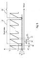
- FIG. 4 illustrates a first example of sequencing for implementing the system according to the invention.
- the radar 11 constituting the device for detecting and locating the system is a multistatic radar, comprising a transmission channel and at least one reception channel, the transmission channel being independent of the reception channels. This configuration allows the system to send and receive signals simultaneously.
- the sequencing illustrated by the figure 4 is a simple sequencing comprising a single phase constituted by the alternation of two periods or recurrences, a period 41 dedicated exclusively to the detection and location tasks performed by the radar 11, and a period 42 during which the radar mainly performs a task of Listens to the signals transmitted by the on-board beacon 12.
- the radar continuously transmits a wave whose frequency changes over time according to a given law, for example a linear law such as the frequency ramp 43 of the figure 4 .
- the emitted signal is thus a signal whose frequency varies from a value f 1 to a value f 2 during the time interval ⁇ T 1 .
- This type of well known waveform allows the radar to achieve, by applying to the received signal the appropriate filtering, a fine measurement of the distance of the guided aircraft.
- the radar 11 being a multistatic radar radar listening and analysis of the received echoes is advantageously performed simultaneously so that at the end of the period 41 the operation in radar mode is completed.
- the mode of operation of the radar is modified in order to perform radio listening of the signals emitted by the beacon.
- these signals are of two natures.
- the locating signal, or beacon signal intended to increase the accuracy of the location of the aircraft by the radar and the signals bearing the information transmitted by the aircraft 13 to the radar 11 for its own use or for that an operational center in connection with the radar.
- the beacon signal is a continuous sinusoidal signal (signal CW) whose frequency f 0 is preferably close to the band in which the radar operates during the periods of location 41 .
- the beacon signal is issued in an interrupted manner even during the periods 41.
- the beacon 12 may have some knowledge of the start times of periods 42 and their durations, especially if these durations are variable over time.
- This listening localization mode is similar to that achieved by some known electromagnetic detection equipment.
- the exchanges of information that can take place between the radar and the beacon during a period 42 are in turn materialized by means of frequency modulated signals according to the appropriate law, a binary law with two frequencies f 4 and f 3 for example as on the illustration of the figure 4 .
- the frequencies f 3 and f 4 are preferably chosen so as to be close to the band in which the radar operates during the period 41 of location. It may be noted that the duration ⁇ T 2 of the period 42 is not necessarily fixed, the necessary condition being that the radar has a signal listening time at the frequency f 0 which is sufficient to perform the localization of the signal. 'aircraft.
- the remaining time can then be used for the exchange of data between the radar 11 and the beacon 12 on board the aircraft; the data exchanged consisting in particular in the altitude information transmitted to the radar 11 by the aircraft 13 and in the information transmitted by the radar to the aircraft, relating to the heading and altitude that the latter must join to follow the good landing trajectory.
- a mode of operation such as that illustrated by the figure 4 for example, has the advantageous characteristic of allowing the integration of the signal received during the successive periods 41.
- the succession of frequency ramps 23, in particular, allows the implementation of a conventional processing on the echoes reflected by the aircraft, Doppler analysis type processing, for example FFT, on the signals received by the radar during N periods 41 successive.
- This Doppler analysis makes it possible to select the echoes of skin of interest before the implementation of telemetry and deviation measurements, and thus to avoid unnecessary calculations.
- the sequencing of the system according to the invention comprises periods 41 of duration ⁇ T 1 during which the radar performs tasks of detection and location of reflected echoes.
- the radar transmits during this period a signal whose frequency follows a law of continuous evolution between a frequency f 1 and a frequency f 2 , a ramp for example.
- the sequencing illustrated by the figure 5 also includes periods 42 of duration ⁇ T 2 during which the radar 11 conducts radio monitoring signals from the beacon 12 on board the aircraft.
- the periods 41 and 42 are not alternated but are arranged so that each period 42 is separated from the next by N periods 41, each period 41 being separated from the next by a time interval 51 whose duration ⁇ T 3 takes into account the propagation times of the processed signals and the processing delays which are in particular a function of the range instrumented by the radar 11.
- the duration ⁇ T 3 may be fixed or may be variable so as to allow the radar to carry out in a known manner operations for eliminating the echoes of nth traces.
- the sequencing of the figure 5 is thus a succession of groups 52 of N periods 41 of duration ⁇ T 1 each group being separated from the next by a listening period 42.
- This type of sequencing is advantageously well suited to the systems according to the invention, the radar 11 of which carries out a doppler analysis of the signal relating to the signal acquisitions carried out during a number N of recurrences. Indeed, the detection and the location are then performed only on the filtered signal, the location obtained after N period 41 can then be associated with the location made from the beacon signal during the period 42 preceding the group of N period 41 considered.
- This sequencing thus has the advantage of limiting the time devoted to the listening periods 42 to the only listening periods that can be associated with a location obtained after N period 41 of detection and radar location.
- FIG 6 illustrates an advantageous variant embodiment of the system according to the invention ( figure 6-a ) and an example of sequencing adapted to this variant ( figure 6-b ).
- this particular embodiment of the system according to the invention comprises a third multifunction beacon 12 ', embarked on board the aircraft with the first beacon 12.
- the two beacons 12 and 12' are arranged so that each alternately they fulfill the functions of communication and resignation of the beacon signal and the altimetry measurement function, the other beacon completing at the same time the altimetric measurement function and the communication functions and resignation of the beacon signal.
- each of the beacons is alternately used to transmit the beacon signal and exchange information with the radar 11, then to make an altitude measurement.
- the system according to the invention also comprises, in this variant, automatic switching means 61.
- automatic switching means 61 The advantage of this variant embodiment of the system according to the invention can be demonstrated by means of the chronogram of sequencing of the figure 6-b proposed by way of non-limiting example.
- the proposed sequencing consists in a succession of groups of N periods 41 during which the radar 11 performs locating tasks on the skin echo of the aircraft, these groups being separated alternately from each other either by a period 62 or by a period 63.
- one of the two embedded tags performs data exchange operations with the radar and ensures the transmission of the beacon signal to the radar, while the second beacon, the beacon 12 'performs other tasks, for example altimetry measurements.
- the other beacon performs the data exchange operations with the radar and ensures the transmission of the beacon signal to the radar, while the first beacon performs other tasks.
- the automatic landing system according to the invention has been described in the foregoing text for a configuration involving a single aircraft.
- This configuration is of course not limiting and the system according to the invention is of course applicable to more complex configurations in which it is advisable to guide and land several aircraft.
- the system according to the invention then comprises at least one detection and location device, for example a radar 11, located on the ground, associated or not with a ground beacon 14, and a plurality of multifunction tags embedded on the ground. aircraft on which the system provides landing.
- Each of the aircraft thus carries, according to the embodiment considered, a beacon 12 or a group of two beacons 12 and 12 '.
Landscapes
- Engineering & Computer Science (AREA)
- Radar, Positioning & Navigation (AREA)
- Remote Sensing (AREA)
- Physics & Mathematics (AREA)
- General Physics & Mathematics (AREA)
- Computer Networks & Wireless Communication (AREA)
- Electromagnetism (AREA)
- Aviation & Aerospace Engineering (AREA)
- Automation & Control Theory (AREA)
- Radar Systems Or Details Thereof (AREA)
- Control Of Position, Course, Altitude, Or Attitude Of Moving Bodies (AREA)
- Traffic Control Systems (AREA)
Description
La présente invention concerne le domaine des aéronefs et en particulier le domaine des aéronefs autonomes et automatiques tels que les drones. Elle concerne plus particulièrement le guidage de ces aéronefs en phase d'approche et d'atterrissage.The present invention relates to the field of aircraft and in particular the field of autonomous and automatic aircraft such as drones. It relates more particularly to the guidance of these aircraft in approach and landing phase.
Les systèmes d'aide à l'atterrissage existants, permettant l'atterrissage d'engins autonomes, sont actuellement basés sur des technologies diverses.Existing landing aid systems, allowing the landing of autonomous craft, are currently based on various technologies.
On peut en premier lieu recourir à des systèmes homologués par l'aviation civile tels que les systèmes ILS (Instrument Landing System) où MLS (Microwave Landing System), et leurs équivalents militaires tel que les radars de type PAR. Ces systèmes sont peu susceptibles d'être déployés rapidement sur un site d'atterrissage car ils demandent la mise en place d'infrastructures relativement importantes au sol. Ils sont donc peu adaptés à la mise en oeuvre et à la récupération de drones.First, civil aviation-approved systems such as ILS (Instrument Landing System) or Microwave Landing System (MLS) and military equivalents such as PAR radars can be used. These systems are unlikely to be deployed quickly to a landing site because they require the installation of relatively large infrastructure on the ground. They are therefore poorly adapted to the implementation and recovery of drones.
Un autre moyen de guider l'atterrissage d'un aéronef consiste à utiliser des systèmes à base de moyens GPS (ou Differential GPS) qui offrent l'avantage d'être d'une mise en oeuvre peu coûteuse. En revanche, Cette solution pose le problème de la disponibilité ou de la continuité de service GPS en mode haute précision. En outre, la vulnérabilité des systèmes GPS en présence de brouilleurs est bien connue,Another way to guide the landing of an aircraft is to use GPS-based systems (or Differential GPS) which offer the advantage of being inexpensive to implement. On the other hand, this solution poses the problem of the availability or the continuity of GPS service in high precision mode. In addition, the vulnerability of GPS systems in the presence of jammers is well known,
Un autre moyen consiste à utiliser des systèmes de télémétrie et de guidage à base de laser qui présentent l'avantage de ne pas nécessiter une logistique de mise en oeuvre importante, mais dont l'emploi présente l'inconvénient d'être dépendant des conditions météorologiques et dont la mise en oeuvre nécessite le passage par une phase de recherche (de "scanning") de l'objet à guider, du fait de l'étroitesse du pinceau émis. De plus un équipement complémentaire de positionnement en absolu par rapport à la piste est nécessaire.Another way is to use laser-based telemetry and guidance systems which have the advantage of not requiring a large implementation logistics, but whose use has the disadvantage of being dependent on the weather conditions. and whose implementation requires the passage of a research phase ("scanning") of the object to be guided, because of the narrowness of the brush emitted. In addition a complementary positioning equipment in absolute relative to the track is necessary.
Un autre moyen encore proche dans son principe du moyen précédent, consiste à utiliser un système de type radar de poursuite ou de trajectographie, très directif, fonctionnant par exemple en bande millimétrique. Ce type de système est cependant sophistiqué et donc coûteux. D'autre part comme les systèmes de télémétrie laser ils nécessitent eux aussi une phase de recherche pour la désignation d'objectifs et un positionnement absolu par rapport à la piste. Ils sont par ailleurs sensibles tant aux conditions climatiques qu'à la conformation du terrain qui constitue la zone d'approche du terrain sur lequel doit se poser l'objet guidé. En particulier, dans le cas où l'on souhaite procéder au guidage de plusieurs aéronefs, il faut effectuer un partage du temps et opérer des ralliements de cible à cible au risque de perdre une cible et de devoir faire une acquisition complète du contexte. En phase d'approche enfin, les contraintes de guidage pour garder la cible dans le faisceau radar sont très importantes.Another means, which is still similar in principle to the preceding means, is to use a radar tracking or tracking system, which is very directional, operating for example in millimetric band. This type of system is however sophisticated and therefore expensive. On the other hand, like the laser telemetry systems, they also require a research phase for the designation of objectives and an absolute positioning with respect to the track. They are also sensitive to both the climatic conditions and the conformation of the terrain which constitutes the approach zone of the ground on which the guided object must be placed. In particular, in the case where it is desired to guide several aircraft, it is necessary to time-sharing and target-to-target rallies at the risk of losing a target and having to make a complete acquisition of the context. Finally, in the approach phase, the guiding constraints to keep the target in the radar beam are very important.
Ces deux derniers moyens étant les plus faciles à déployer sur un terrain d'atterrissage non équipé, ils constituent les systèmes de guidage les plus couramment mis en oeuvre. Cependant, s'agissant de systèmes d'émission à pinceaux étroits opérant par pointage de la cible depuis le sol, leur mise en oeuvre passe par une phase de recherche et par un accrochage dynamique sur la cible. Les risques de décrochage et donc d'interruption du guidage sont importants. Lorsque la liaison est critique, une interruption de la poursuite peu engendrer un guindage erratique aux conséquences parfois fatales pour l'aéronef. En outre, ces solutions sont généralement coûteuses et comportent des limitations concernant en particulier l'asservissement du faisceau émis sur la position de la cible en mouvement d'approche, limitations mécaniques qui trouvent leur origine dans les servocommandes. D'autre part, s'agissant de systèmes de détection asservis sur une cible particulière, ces systèmes sont peu adaptés au guidage simultané de plusieurs drones en approche d'une zone d'atterrissage.These last two means being the easiest to deploy on a non-equipped landing ground, they are the most commonly used guidance systems. However, in the case of narrow brush emission systems operating by aiming the target from the ground, their implementation goes through a search phase and a dynamic coupling on the target. The risks of stall and therefore interruption of the guidance are important. When the link is critical, an interruption of the pursuit may lead to an erratic windshield with sometimes fatal consequences for the aircraft. In addition, these solutions are generally expensive and include limitations concerning in particular the servocontrol of the emitted beam on the position of the target in approach movement, mechanical limitations that originate in the servocontrols. On the other hand, with regard to detection systems enslaved to a particular target, these systems are poorly adapted to the simultaneous guidance of several drones approaching a landing zone.
Le document de brevet publié sous la référence
Un but de l'invention consiste à proposer une solution alternative aux dispositifs existants. A cet effet, l'invention a pour objet un système de guidage pour l'atterrissage automatique d'aéronefs caractérisé en ce qu'il comporte au moins :
- un dispositif électromagnétique de détection et de localisation, positionné au sol pour mesurer, pour au moins un aéronef, la distance le séparant de l'aéronef et la position angulaire dudit aéronef par rapport à une direction de référence, à partir de l'écho réfléchi par ledit aéronef,
- une première balise radioélectrique multifonction embarquée sur chaque aéronef guidé, la balise comportant des moyens pour échanger des informations avec le dispositif de détection et pour former une source ponctuelle émettant vers le dispositif de détection une onde sinusoïdale continue,
- an electromagnetic detection and locating device, positioned on the ground, for measuring, for at least one aircraft, the distance separating it from the aircraft and the angular position of said aircraft with respect to a reference direction, from the reflected echo by said aircraft,
- a first multifunction radio beacon embedded on each guided aircraft, the beacon comprising means for exchanging information with the detection device and for forming a point source transmitting a continuous sinusoidal wave towards the detection device,
Selon une forme de réalisation préférée, le système selon l'invention comporte en outre une deuxième balise radioélectrique placée au sol au niveau du point de contact de l'aéronef avec le sol pour permettre au dispositif de détection et de localisation d'effectuer des mesures différentielles de la distance et de la position angulaire de l'aéronef. La balise au sol comporte des moyens passifs permettant au dispositif de détection et de localisation de différentier l'écho réfléchi par cette balise d'un écho fixe.According to a preferred embodiment, the system according to the invention further comprises a second radio beacon placed on the ground at the point of contact of the aircraft with the ground to enable the detection and localization device to perform measurements. differentials in the distance and angular position of the aircraft. The ground beacon comprises passive means enabling the detection and localization device to differentiate the echo reflected by this beacon with a fixed echo.
Selon une variante de réalisation préférée, ces moyens passifs sont constitués par les pales d'un ventilateur en mouvement.According to a preferred embodiment, these passive means are constituted by the blades of a moving fan.
Selon une autre forme de réalisation du système selon l'invention, la première balise multifonction, embarquée à bord de l'aéronef, comporte également des moyens pour réaliser des mesures d'altitude, ladite balise remplissant la fonction de radio altimètre, la balise transmettant de manière périodique au dispositif de détection et de localisation des informations relatives à l'altitude de l'aéronef, altitude mesurée par ladite balise, le dispositif de détection et de localisation exploitant les informations d'altitude transmises par la balise pour améliorer la précision de la mesure de la position angulaire de l'aéronef.According to another embodiment of the system according to the invention, the first multifunction beacon, embarked on board the aircraft, also comprises means for making altitude measurements, said beacon fulfilling the function of radio altimeter, the transmitting beacon periodically to the device for detecting and locating information relating to the altitude of the aircraft, the altitude measured by said beacon, the detection and location device exploiting the altitude information transmitted by the beacon to improve the accuracy of the measurement of the angular position of the aircraft.
Selon un mode particulier de mise en oeuvre de l'invention, le fonctionnement du dispositif de détection et de localisation alterne des périodes de localisation active, de durée ΔT1, durant lesquelles il mesure la distance et la position angulaire de l'aéronef à partir de l'écho réfléchi par ledit aéronef et des périodes d'écoute et d'échange de données, de durée ΔT2, durant lesquelles il mesure la position angulaire de l'aéronef à partir du signal émis par la balise, et durant lesquels il transmet des informations de positionnement à l'aéronef.According to a particular mode of implementation of the invention, the operation of the detection and localization device alternates periods of localization active, duration ΔT1, during which it measures the distance and the angular position of the aircraft from the echo reflected by said aircraft and listening periods and data exchange, duration ΔT2, during which it measures the angular position of the aircraft from the signal transmitted by the beacon, and during which it transmits positioning information to the aircraft.
Selon un autre mode particulier de mise en oeuvre de l'invention, le dispositif de détection et de localisation exploite les signaux reçus au cours des N périodes de localisation active formant un même groupe pour réaliser un filtrage doppler du signal, le signal filtré étant utilisé pour effectuer la mesure de la distance et de la position angulaire de l'aéronef, cette mesure étant exploitée conjointement avec la mesure de position angulaire obtenue à partir du signal émis par la balise, lors de la période d'écoute et d'échange de données qui précède ledit groupe, et avec la mesure d'altitude transmise par la balise durant cette même période.According to another particular embodiment of the invention, the detection and localization device exploits the signals received during the N active positioning periods forming a same group to perform a doppler filtering of the signal, the filtered signal being used. for measuring the distance and the angular position of the aircraft, this measurement being used together with the angular position measurement obtained from the signal transmitted by the beacon during the listening and exchange period of the aircraft. data preceding said group, and with the altitude measurement transmitted by the beacon during this same period.
Selon une autre forme de réalisation de l'invention, le système comporte une troisième balise radioélectrique multifonction, identique à la première balise et embarquée avec la première balise sur chaque aéronef guidé, et des moyens permettant d'utiliser alternativement chaque balise pour effectuer les tâche d'échange d'informations avec le dispositif de détection et de localisation, ainsi que la tâche de réalisation d'une source d'émission ponctuelle, pendant que l'autre balise effectue les mesures d'altitude.According to another embodiment of the invention, the system comprises a third multifunction radio beacon, identical to the first beacon and embarked with the first beacon on each guided aircraft, and means making it possible to use each beacon alternately to perform the tasks. exchanging information with the detection and location device, as well as the task of producing a point source of emission, while the other beacon makes altitude measurements.
Dans un mode particulier de mise en oeuvre de cette forme de réalisation, le fonctionnement du dispositif de détection et de localisation alterne des groupes de N périodes de localisation active, de durée ΔT1, durant lesquelles il mesure la distance et la position angulaire de l'aéronef à partir de l'écho réfléchi par ledit aéronef, et des périodes d'écoute et d'échange de données, de durée ΔT2, durant lesquelles il mesure la position angulaire de l'aéronef à partir du signal émis par une des balises radioélectriques multifonctions. Durant ces périodes de durée ΔT2 il transmet également des informations de positionnement à l'aéronef par l'intermédiaire de ladite balise. Chaque groupe de périodes de localisation active est alors séparé du groupe suivant par une période d'écoute et d'échange de données. La tache d'échange d'informations avec le dispositif de détection et de localisation, ainsi que la tâche de réalisation d'une source d'émission ponctuelle, est réalisées alternativement, d'une période d'écoute et d'échange de données à l'autre, par la première et par la deuxième balise.
Le dispositif proposé présente avantageusement une plus grande robustesse vis à vis des conditions géographiques et climatiques que les dispositifs existants. Il présente également l'avantage d'être de conception plus simple et donc moins, coûteuse. Il dispose en outre avantageusement la capacité de guider simultanément plusieurs aéronef vers la zone d'atterrissage.In a particular mode of implementation of this embodiment, the operation of the detection and localization device alternates groups of N active positioning periods, of duration ΔT1, during which it measures the distance and the angular position of the aircraft from the echo reflected by said aircraft, and listening and data exchange periods, duration ΔT2, during which it measures the angular position of the aircraft from the signal transmitted by one of the radio beacons multifunction. During these periods of duration ΔT 2 it also transmits positioning information to the aircraft via said beacon. Each group of active locating periods is then separated from the next group by a period of listening and data exchange. The task of exchanging information with the detection and localization device, as well as the task of producing a point source of emission, is carried out alternately, from a period of listening and data exchange to the other, by the first and the second beacon.
The proposed device advantageously has a greater robustness with respect to geographical and climatic conditions than existing devices. It also has the advantage of being simpler design and therefore less expensive. It also advantageously has the ability to simultaneously guide several aircraft to the landing zone.
Les caractéristiques et avantages de l'invention apparaîtront clairement dans la description qui suit, description illustrée par les figures annexées qui représentent:
- la
figure 1 , l'illustration du principe de fonctionnement d'un système selon l'invention de guidage automatique d'aéronefs en phase d'approche et d'atterrissage, - la
figure 2 , une illustration schématique du principe de détermination de la distance et de l'élévation d'un aéronef en approche, - la
figure 3 , une illustration schématique du principe de détermination de la direction d'approche d'un aéronef, - la
figure 4 , un premier exemple de chronogramme type de cadencement des différentes tâches remplies par le système selon l'invention. les lafigure 1 , - la
figure 5 , un deuxième exemple de chronogramme type de cadencement des différentes tâches remplies par le système selon l'invention.
- the
figure 1 , the illustration of the principle of operation of a system according to the invention of automatic guidance of aircraft in approach and landing phase, - the
figure 2 , a schematic illustration of the principle of determining the distance and elevation of an aircraft on approach, - the
figure 3 , a schematic illustration of the principle of determining the approach direction of an aircraft, - the
figure 4 , a first example of a typical chronogram of timing of the different tasks performed by the system according to the invention. the thefigure 1 , - the
figure 5 , a second example of a typical chronogram of timing of the different tasks performed by the system according to the invention.
On s'intéresse tout d'abord aux
Pour procéder au guidage automatique d'un aéronef en phase d'atterrissage, le système selon l'invention comporte principalement un dispositif de détection et de localisation 11, situé au sol, et une balise multifonctions 12 embarqué à bord de l'aéronef 13.
Le dispositif de détection 11 a pour principale fonction de mesurer de manière périodique l'altitude h de l'aéronef 13 ainsi que la distance radiale D qui sépare l'aéronef du point sur lequel il est situé. Il mesure également les écarts de direction et d'altitude existant entre la direction joignant ce dispositif à l'aéronef et une direction de référence, de préférence parallèle à l'axe de la piste sur laquelle l'aéronef est sensé atterrir. Pour ce faire, met en oeuvre par exemple des mesures d'écartométrie angulaire, connue par ailleurs, lui permettant de déterminer l'azimut et l'élévation relatives à l'aéronef guidé. Ce dispositif peut par exemple, dans un mode de réalisation particulier, être constitué de manière relativement simple par un radar d'atterrissage constitué par un radar de veille classique équipé des moyens de réaliser des mesures d'écartométrie angulaire et pointé de manière fixe dans une direction donnée qui correspond globalement à la direction d'approche optimale de la piste d'atterrissage. Selon l'invention ce radar d'atterrissage présentant un diagramme de rayonnement suffisamment large pour intercepter un ou plusieurs aéronefs en approche sans avoir à procéder à une opération de recherche. Dans un mode de réalisation particulier plus sophistiqué, le dispositif de détection 11 peut également consister en un radar équipé d'une antenne active permettant de former plusieurs faisceaux de réception dans des directions choisies. Un tel dispositif peut avantageusement être utilisé en particulier lorsque le fonctionnement du système est potentiellement perturbé par des réflexions multiples des échos radar sur le sol ainsi que sur des éléments de faible hauteur, des bâtiments ou des véhicules par exemple, posés sur le sol.To carry out the automatic guidance of an aircraft during the landing phase, the system according to the invention mainly comprises a detection and
The main function of the
La position de l'aéronef est déterminée par le radar par mise en oeuvre de calculs de télémétrie et d'écartométrie angulaire, connus par ailleurs et non développées ici. L'intégration au cours du temps des positions successives de l'aéronef permet au radar de déterminer sa trajectoire de ce dernier. Cette trajectoire, est comparée par le calculateur du radar à la trajectoire permettant à l'aéronef de rallier son point d'atterrissage. Le calculateur détermine en particulier à chaque mesure l'écart Δp existant entre la position réelle de l'aéronef à l'instant de la mesure et la position où se situerait le même aéronef suivant la trajectoire de ralliement. La trajectoire de ralliement est symbolisée par la courbe en pointillés 14 dont les projections sont représentées sur les
La balise multifonctions 14, embarquée par l'aéronef, remplit à la fois des fonctions autonomes de mesure et des fonctions de balise répondeuse, ainsi que des fonctions de communication. Le radar 11 et la balise 12 forment les éléments de base du système selon l'invention.The
En phase stabilisée, lorsqu'un aéronef est pris en charge par le système, le fonctionnement du système radar-balise suit de manière globale le schéma général suivant.
le radar 11 procède de manière périodique à la localisation de l'aéronef et détermine l'écart entre cette position et la position correspondant à une trajectoire permettant un atterrissage satisfaisant.- cet écart est utilisé par le calculateur du radar pour élaborer des informations de correction de trajectoire qui sont transmises à la balise 12 de l'aéronef,
- la balise multifonctions 12 reçoit les informations provenant du
radar 11. et les communique au calculateur de l'aéronef 13 qui effectue la correction correspondante.
- the
radar 11 proceeds periodically to the location of the aircraft and determines the difference between this position and the position corresponding to a path for a satisfactory landing. - this difference is used by the radar calculator to produce trajectory correction information which is transmitted to the
beacon 12 of the aircraft, - the
multifunction beacon 12 receives the information from theradar 11. and communicates to the computer of theaircraft 13 which performs the corresponding correction.
De façon à accroître la précision des mesures de position, effectuées par le radar 11, la balise multifonction 12 assure également la fonction complémentaire de radio altimètre. A cet effet la balise embarquée comporte un émetteur-récepteur ainsi qu'un calculateur destiné notamment au traitement des signaux reçus. La balise 12 comporte également une antenne positionnée sous l'aéronef et dirigée vers le sol. La mesure d'altitude est réalisée, de manière connue, par mesure du temps de parcours d'une onde émise et réfléchie par le sol. Selon l'invention, les résultats de mesures sont transmis au radar qui les utilise le cas échéant pour corriger l'altitude de l'aéronef 13 déterminée à l'aide de l'écho radar. L'information d'altitude fournie par la balise 12 est plus particulièrement utilisée à partir de l'instant où l'aéronef se situe à une distance relativement proche du point d'atterrissage car dans cette phase la précision sur la mesure d'altitude devient importante.
Outre la fonction de balise répondeuse et de radio altimètre, la balise multifonctions 12 joue le rôle d'une source ponctuelle émettant vers l'avant de l'aéronef 13 un signal dont le niveau est sensiblement supérieur au niveau de l'écho de peau réfléchi par l'aéronef 13. A cet effet elle dispose d'une antenne, positionnée à l'avant de l'aéronef le long de la ligne médiane et dirigée vers l'avant. Selon l'invention, le diagramme de rayonnement de cette antenne a la forme d'un pinceau étroit de sorte que le signal ainsi émis est détecté par le radar comme provenant d'une source ponctuelle et peut être utilisé par le radar 11 pour déterminer de manière précise la position angulaire de l'aéronef 13 avec une meilleure précision que celle obtenue à partir de l'écho de peau réfléchi. L'écho de peau peut en effet provenir de diverses parties scintillantes du fuselage de l'aéronef, ces éléments scintillants du fuselage se trouvant placés à une distance plus ou moins grande de l'axe médian 31 de l'aéronef. Ce peut par exemple être les bords des ailes.
Le biais induit par la dispersion des points scintillants sur le fuselage, se traduit en pratique par une erreur sur la mesure de position angulaire (angles α et β) de l'aéronef 13 par le radar 11. Selon l'invention, cette erreur peut avantageusement être corrigée par comparaison de la position angulaire déterminée à partir de l'écho radar et de la position angulaire déterminée à partir du signal émis par la balise 12.
Le signal émis peut avantageusement consister en un simple signal CW à fréquence, f0 unique, émis en continue sur une fréquence située en dehors de la bande utilisée pour la localisation radar. La balise 16 est alors un dispositif simple émettant en continues un signal à une fréquenceIn order to increase the accuracy of the position measurements made by the
In addition to the answering beacon and altimeter radio function, the
The bias induced by the dispersion of the scintillating points on the fuselage, is translated in practice by an error on the measurement of angular position (angles α and β) of the
The transmitted signal may advantageously consist of a single frequency CW signal, f 0 unique, transmitted continuously on a frequency located outside the band used for the radar location. The
Comme il a été dit précédemment, les mesures des positions successives de l'aéronef au cours du temps, effectuées par le radar 11, permettent à celui-ci d'élaborer des informations de correction destinées à l'aéronef 13. Ces informations sont utilisées par ce dernier pour corriger sa trajectoire de proche en proche, jusqu'à rallier la trajectoire d'atterrissage 14. Les informations, ou ordres, de correction sont transmises à l'aéronef par la voie de communication dont dispose la balise multifonction 12. Cette voie de communication est une voie bidirectionnelle qui permet en outre à l'aéronef 13 de communiquer son altitude au radar 11. Elle permet également à l'aéronef de communiquer avec un centre opérationnel en relation avec le radar et de lui faire parvenir diverses informations, relatives par exemple au données collectées pendant la mission effectuée. Elle permet enfin de transmettre au radar 11 diverses informations relatives à l'identification de l'aéronef 13 et au bon fonctionnement des équipements embarqués à bord.As has been said previously, the measurements of the successive positions of the aircraft over time, carried out by the
Dans le but de renforcer la précision de la mesure de distance le système selon l'invention peut également comporter une deuxième balise multifonction 15, fixe, positionnée au sol le long de la piste d'atterrissage en regard du point de contact 16 de l'aéronef avec le sol. Les déterminations successives de la position de l'aéronef 13 par rapport à ce point 14 peuvent ainsi être effectuées de manière différentielle à partir des mesures de la distance de l'aéronef 13 et de la distance de la balise au sol 15 effectuées par le radar 11, et être ainsi exemptes de biais.
Afin de pouvoir différentier l'écho provenant de la balise multifonction additionnelle 15, balise fixe posée au sol, d'un écho fixe pouvant être éliminé par traitement, cette balise comporte avantageusement des moyens lui permettant de rétrodiffuser vers le radar un écho dont la fréquence présente un décalage doppler.In order to reinforce the accuracy of the distance measurement, the system according to the invention may also comprise a second fixed
In order to be able to differentiate the echo coming from the
Dans un mode de réalisation préféré, ces moyens consistent en un réflecteur mobile constitué par exemple par un ventilateur en mouvement. Ce mode de réalisation particulier, est particulièrement avantageux car la balise au sol reste un simple dispositif passif au regard de la détection radar. Cependant, toute autre solution permettant de produire un signal synchrone du signal émis par le radar et présentant un décalage doppler, est bien entendu envisageable quoique plus complexe à mettre en oeuvre.In a preferred embodiment, these means consist of a movable reflector constituted for example by a moving fan. This particular embodiment is particularly advantageous because the ground beacon remains a simple passive device with regard to radar detection. However, any other solution for producing a synchronous signal of the signal transmitted by the radar and having a Doppler shift, is of course conceivable although more complex to implement.
Pour des raisons de commodité, la deuxième balise multifonctions 15 posée au sol et destinée à accroître la précision de la mesure de distance, peut être de même type que la balise multifonctions embarquée à bord de l'aéronef et à ce titre comporter une fonction de communication, fonction qui peut par exemple être mise avantageusement à profit pour transmettre au radar un message relatif à son état de fonctionnement.For the sake of convenience, the
Ainsi, selon l'invention, le guidage de l'aéronef 13 est réalisé au moyen de mesures successives de positions effectuées par le radar 11 à partir de l'écho de peau réfléchi par l'aéronef. Ces mesures peuvent avantageusement être affinées par l'exploitation conjointe de mesures effectuées sur le signal ponctuel émis par la balise 12 située à bord de l'aéronef, ainsi que par l'exploitation de la mesure d'altitude réalisée par la balise 12 et transmise au radar au travers des moyens bidirectionnels de communication dont elle dispose.
Par ailleurs, les mesures réalisées à partir de l'écho réfléchi par l'aéronef peuvent également être débarrassées de tout biais en ajoutant au système une deuxième balise 15 posée au sol au niveau du point d'atterrissage, le long de la piste. Cette deuxième balise permet avantageusement au radar de réaliser des mesures de télémétrie et d'écartométrie différentielles sur l'aéronef.Thus, according to the invention, the guidance of the
Furthermore, the measurements made from the echo reflected by the aircraft can also be cleared of any bias by adding to the system a
Ce système simple, basé sur l'utilisation d'un radar classique disposant d'un diagramme de rayonnement large présente de nombreux avantages par rapport aux autres systèmes de guidage cités, connus de l'art antérieur. Dans la mesure où son fonctionnement ne nécessite pas un pointage permanent et précis d'un faisceau de guidage sur l'objet à guider, Il permet en particulier de guider plusieurs aéronefs simultanément avec une précision satisfaisante tout en mettant en oeuvre un minimum de moyens.
La balise embarquée à bord de l'aéronef peut, quant à elle, avantageusement remplir d'autres fonctions que la réalisation d'un écho ponctuel. Elle peut par exemple permettre l'identification de l'aéronef 13 sur lequel elle est embarquée. Ainsi, dans le cas où le système selon l'invention est utilisé pour le guidage automatique de plusieurs aéronefs, chaque aéronef peut être identifié par un indicatif propre.This simple system, based on the use of a conventional radar having a broad radiation pattern has many advantages over other guidance systems cited, known from the prior art. Since its operation does not require a permanent and precise pointing of a guide beam on the object to be guided, it allows in particular to guide several aircraft simultaneously with a satisfactory accuracy while implementing a minimum of means.
The beacon embedded on board the aircraft can, for its part, advantageously fulfill other functions than the achievement of a one-off echo. It can for example allow identification of the
Le système selon l'invention présente également l'avantage d'être facile à installer, même sur une zone d'atterrissage improvisée, d'avoir une portée satisfaisante et d'être peu dépendant des conditions atmosphériques. Il représente donc un moyen globalement très avantageux pour réaliser le guidage de drones et faciliter leur atterrissage sur des terrains improvisés et temporaires, ne disposant pas de moyens d'aide à l'atterrissage automatique plus classique.The system according to the invention also has the advantage of being easy to install, even on an improvised landing zone, to have a satisfactory range and to be little dependent on atmospheric conditions. It therefore represents a globally very advantageous way to realize the guidance of drones and facilitate their landing on improvised and temporary terrain, not having means of assistance for the more conventional automatic landing.
On s'intéresse à présente à la
Dans l'exemple de la
Le séquencement illustré par la
Durant chaque période 42, le mode de fonctionnement du radar se modifie afin de réaliser une écoute radioélectrique des signaux émis par la balise. Comme il a été dit précédemment, ces signaux sont de deux natures. On distingue en effet le signal de localisation, ou signal balise, destiné à accroître la précision de localisation de l'aéronef par le radar et les signaux portant les informations transmises par l'aéronef 13 au radar 11 à son usage propre ou bien à celui d'un centre opérationnel en liaison avec le radar. Selon un mode de réalisation préféré, mis non exclusif, de l'invention le signal balise est un signal sinusoïdal continu (signal CW) dont la fréquence f0 est de préférence proche de la bande dans laquelle fonctionne le radar durant la périodes 41 de localisation. De la sorte aucun changement de fréquence de l'oscillateur local du récepteur du radar 11 n'est à effectuer lorsque l'on passe de la période 41 à la période 42.
Dans ce même mode de réalisation préféré, par souci de simplification de la synchronisation des tâches, le signal balise est émis de manière interrompue même durant les périodes 41. cependant il est évidemment possible de limiter cette émission aux périodes 42 à condition toutefois que la balise 12 puisse avoir connaissance d'une façon quelconque des instants de début des périodes 42 ainsi que de leurs durées, notamment si ces durées sont variables au cours du temps.
Ce mode de localisation par écoute est semblable à celui réalisé par certains équipement de détection électromagnétique connus.
Les échanges d'informations pouvant avoir lieu entre le radar et la balise durant une période 42 sont quant à eux matérialisé au moyen de signaux modulés en fréquence selon la loi appropriée, une loi binaire à deux fréquences f4 et f3 par exemple comme sur l'illustration de la
On peut noter que la durée ΔT2 de la période 42 n'est pas nécessairement fixe, la condition nécessaire étant que le radar dispose d'un temps d'écoute du signal à la fréquence f0 qui soit suffisant pour effectuer la localisation de l'aéronef. Le temps restant peut ensuite être utilisé pour l'échange de données entre le radar 11 et la balise 12 embarquée sur l'aéronef; les données échangées consistant notamment dans l'information d'altitude transmise au radar 11 par l'aéronef 13 et dans les informations transmises par le radar à l'aéronef, relatives au cap et à l'altitude que ce dernier doit rallier pour suivre la bonne trajectoire d'atterrissage.
La durée ΔT2 peut, en particulier, également varier au cours du temps de façon à faire varier la durée totale ΔT = ΔT1+ΔT2 pour permettre au radar de réaliser de manière connue des opérations d'élimination des échos de nièmes traces.During each
In this same preferred embodiment, for the sake of simplification of the synchronization of tasks, the beacon signal is issued in an interrupted manner even during the
This listening localization mode is similar to that achieved by some known electromagnetic detection equipment.
The exchanges of information that can take place between the radar and the beacon during a
It may be noted that the duration ΔT 2 of the
The duration ΔT 2 may, in particular, also vary over time so as to vary the total duration ΔT = ΔT 1 + ΔT 2 to allow the radar to perform in a known manner operations for eliminating the echoes of nth traces.
Un mode de fonctionnement, tel que celui illustré par la
On s'intéresse à présente à la
Le séquencement de la
Ce type de séquencement est avantageusement bien adapté aux systèmes selon l'invention dont le radar 11 réalise une analyse doppler du signal portant sur les acquisitions de signal réalisées pendant un nombre N de récurrences. En effet, la détection et la localisation ne sont alors effectuée que sur le signal filtré, la localisation obtenue après N période 41 pouvant alors être associé à la localisation réalisée à partir du signal balise durant la période 42 précédente le groupe de N période 41 considéré. Ce séquencement présente ainsi l'avantage de limiter le temps consacré aux périodes d'écoute 42 aux seules périodes d'écoute pouvant être associées à une localisation obtenue après N période 41 de détection et de localisation radar.We are interested in present at the
The sequencing of the
This type of sequencing is advantageously well suited to the systems according to the invention, the
On s'intéresse à présente à la
Comme l'illustre la
L'intérêt de cette variante de réalisation du système selon l'invention peut être mis en évidence au moyen du chronogramme de séquencement de la
As illustrated by
The advantage of this variant embodiment of the system according to the invention can be demonstrated by means of the chronogram of sequencing of the
Ce mode particulier de réalisation, associé à un séquencement approprié du type de celui illustré par la
Dans le but de faciliter l'exposé, le système d'atterrissage automatique selon l'invention a été décrit dans le texte qui précède, pour une configuration mettant en jeu un seul aéronef. Cette configuration n'est bien entendu pas limitative et le système selon l'invention est bien entendu applicable à des configurations plus complexes dans lesquelles il convient de guider et de faire atterrir plusieurs aéronefs. Dans une telle configuration le système selon l'invention comporte alors au moins un dispositif de détection et de localisation, par exemple un radar 11, situé au sol, associé ou non à une balise au sol 14, et une pluralité de balises multifonctions embarquées à bord des aéronefs dont le système assure l'atterrissage. Chacun des aéronefs emporte ainsi, selon le mode de réalisation considéré, une balise12 ou un groupe de deux balises 12 et 12'.In order to facilitate the presentation, the automatic landing system according to the invention has been described in the foregoing text for a configuration involving a single aircraft. This configuration is of course not limiting and the system according to the invention is of course applicable to more complex configurations in which it is advisable to guide and land several aircraft. In such a configuration, the system according to the invention then comprises at least one detection and location device, for example a
Claims (14)
- A guidance system for the automatic landing of aircrafts comprising at least:- an electromagnetic detection and localisation device, positioned on the ground for measuring, for at least one aircraft, the distance between it and said aircraft and the angular position of said aircraft in relation to a reference direction, using the echo reflected by said aircraft,- a first multi-function radioelectric beacon on board each guided aircraft,the beacon and the electromagnetic detection device comprising means for exchanging information, characterised in that the beacon comprising means for forming a point source emitting a continuous sinusoidal wave to the detection device, the detection and localisation device using the continuous wave emitted by the beacon to perform passive localisation and associating it with the echo reflected by the aircraft, in order to improve the accuracy of the angular position measurement of the aircraft and periodically generating and transmitting to the aircraft, by means of the beacon, information allowing said aircraft to find an optimal landing trajectory from its position.
- System according to claim 1, further comprising a second radioelectric beacon positioned on the ground at the point of contact of the aircraft with the ground to allow the detection and localisation device to perform differential measurements of the distance and of the angular position of the aircraft.
- System according to claim 2, wherein the second beacon comprises passive means allowing the detection and localisation system to differentiate the echo reflected by this beacon from a fixed echo.
- System according to claim 3, wherein said passive means is formed by the moving vanes of a fan.
- System according to any one of claims 1 or 2, wherein the on board multi-function beacon comprises means for realising altitude measurements, said beacon fulfilling a radio altimeter function.
- System according to claim 3, wherein the beacon periodically transmits information relative to the altitude of the aircraft, as measured by said beacon, to the detection and localisation system.
- System according to claim 4, wherein the detection and localisation device uses the altitude information transmitted by the beacon to improve the accuracy of the angular position measurement of the aircraft.
- System according to any one of the previous claims, wherein the operation of the detection and localisation device alternates between active localisation periods, of duration Owt1, during which it measures the distance and the angular position of the aircraft from the echo reflected by said aircraft, and listening and data exchange periods, of duration ΔT2, during which it measures the angular position of the aircraft from the signal transmitted by the beacon and transmits positioning information to the aircraft.
- System according to any one of claims 1 to 5, wherein the operation of the detection and localisation device alternates between groups of N active localisation periods, of duration ΔT1, during which it measures the distance and the angular position of the aircraft from the echo reflected by said aircraft, and listening and data exchange periods, of duration ΔT2, during which it measures the angular position of the aircraft from the signal emitted by the beacon and transmits positioning information to the aircraft, each group of active localisation periods being separated from the next group by a listening and data exchange period.
- System according to claim 7, wherein the detection and localisation device uses the signals received during the N active localisation periods forming the same group in order to perform Doppler filtering of the signal, the filtered signal being used to perform the distance and angular position measurement of the aircraft, said measurement being used together with the angular position measurement obtained from the signal transmitted by the beacon during the listening and data exchange period which precedes the said group and with the altitude measurement transmitted by the beacon during this same period.
- system according to any one of claims 1 to 5, comprising a third multi-function radioelectric beacon, identical to the first beacon and located with the first beacon on board each guided aircraft, and means allowing each beacon to be used alternately to perform the information exchange tasks with the detection and localisation device, as well as the task of realising a punctual source of emission, whilst the other beacon performs altitude measurements.
- System according to claim 9, wherein the operation of the detection and localisation device alternates between groups of N active localisation periods, of duration ΔT1, during which it measures the distance and the angular position of the aircraft from the echo reflected by said aircraft, and listening and data exchange periods, of duration ΔT2, during which it measures the angular position of the aircraft from the signal transmitted by one of the multi-function radioelectric beacons, and transmits positioning information to the aircraft by means of said beacon; each group of active localisation periods being separated from the next group by a listening and data exchange period; the information exchange task with the detection and localisation device, as well as the task of realising a punctual source of emission, being realised alternately, from one listening and data exchange period to another, by the first and the second beacon.
- System according to any one of the previous claims, wherein the detection and localisation device is a radar comprising means for performing distance and angular localisation measurements.
- System according to claim 11, wherein the radar is a beamforming radar.
Applications Claiming Priority (2)
| Application Number | Priority Date | Filing Date | Title |
|---|---|---|---|
| FR0512257A FR2894347B1 (en) | 2005-12-02 | 2005-12-02 | AUTONOMOUS AND AUTOMATIC LANDING SYSTEM FOR DRONES. |
| PCT/EP2006/069198 WO2007063126A1 (en) | 2005-12-02 | 2006-12-01 | Autonomous and automatic landing system for drones |
Publications (2)
| Publication Number | Publication Date |
|---|---|
| EP1963942A1 EP1963942A1 (en) | 2008-09-03 |
| EP1963942B1 true EP1963942B1 (en) | 2010-02-24 |
Family
ID=36764331
Family Applications (1)
| Application Number | Title | Priority Date | Filing Date |
|---|---|---|---|
| EP06819896A Active EP1963942B1 (en) | 2005-12-02 | 2006-12-01 | Autonomous and automatic landing system for drones |
Country Status (6)
| Country | Link |
|---|---|
| US (1) | US8265808B2 (en) |
| EP (1) | EP1963942B1 (en) |
| DE (1) | DE602006012544D1 (en) |
| FR (1) | FR2894347B1 (en) |
| IL (1) | IL191867A (en) |
| WO (1) | WO2007063126A1 (en) |
Cited By (1)
| Publication number | Priority date | Publication date | Assignee | Title |
|---|---|---|---|---|
| DE102018120201A1 (en) * | 2018-08-20 | 2020-02-20 | Dr. Ing. H.C. F. Porsche Aktiengesellschaft | Landing guidance system for an aircraft and corresponding aircraft |
Families Citing this family (65)
| Publication number | Priority date | Publication date | Assignee | Title |
|---|---|---|---|---|
| US7908077B2 (en) * | 2003-06-10 | 2011-03-15 | Itt Manufacturing Enterprises, Inc. | Land use compatibility planning software |
| US20100079342A1 (en) * | 1999-03-05 | 2010-04-01 | Smith Alexander E | Multilateration enhancements for noise and operations management |
| US7739167B2 (en) | 1999-03-05 | 2010-06-15 | Era Systems Corporation | Automated management of airport revenues |
| US7889133B2 (en) | 1999-03-05 | 2011-02-15 | Itt Manufacturing Enterprises, Inc. | Multilateration enhancements for noise and operations management |
| US7667647B2 (en) * | 1999-03-05 | 2010-02-23 | Era Systems Corporation | Extension of aircraft tracking and positive identification from movement areas into non-movement areas |
| US7777675B2 (en) * | 1999-03-05 | 2010-08-17 | Era Systems Corporation | Deployable passive broadband aircraft tracking |
| US7782256B2 (en) | 1999-03-05 | 2010-08-24 | Era Systems Corporation | Enhanced passive coherent location techniques to track and identify UAVs, UCAVs, MAVs, and other objects |
| US7570214B2 (en) | 1999-03-05 | 2009-08-04 | Era Systems, Inc. | Method and apparatus for ADS-B validation, active and passive multilateration, and elliptical surviellance |
| US8203486B1 (en) | 1999-03-05 | 2012-06-19 | Omnipol A.S. | Transmitter independent techniques to extend the performance of passive coherent location |
| US8446321B2 (en) | 1999-03-05 | 2013-05-21 | Omnipol A.S. | Deployable intelligence and tracking system for homeland security and search and rescue |
| US7965227B2 (en) | 2006-05-08 | 2011-06-21 | Era Systems, Inc. | Aircraft tracking using low cost tagging as a discriminator |
| US7953524B1 (en) * | 2008-02-29 | 2011-05-31 | Rockwell Collins, Inc. | Navigation through reception of a remote position fix via data link |
| FR2929414A1 (en) * | 2008-04-01 | 2009-10-02 | Thales Sa | RADAR DETECTION METHOD OF A KNOWN TARGET LIKELY TO BE SUBSEQUENTLY DISPOSED AT A GIVEN HEIGHT, CLOSE TO OTHER TARGETS SUBSTANTIALLY PLACED AT THE SAME HEIGHT |
| FR2937169B1 (en) * | 2008-10-13 | 2011-09-30 | Dcns | SYSTEM FOR GUIDING A DRONE IN THE APPROACH PHASE OF A PLATFORM, IN PARTICULAR NAVAL, FOR ITS APPROVAL |
| FR2937010B1 (en) * | 2008-10-13 | 2010-12-10 | Dcns | METHOD AND SYSTEM FOR MONITORING THE AUTOMATIC APPROVAL / TAKING OF A DRONE ON OR A CIRCULAR GRID FOR APPROVAL OF A PARTICULARLY NAVAL PLATFORM |
| AU2009327362A1 (en) * | 2008-12-19 | 2011-08-04 | Xollai, Llc | System and method for determining an orientation and position of an object |
| FR2944128B1 (en) | 2009-04-03 | 2016-01-29 | Thales Sa | SYSTEM AND METHOD FOR APPROVING AN AIRCRAFT |
| FR2945889B1 (en) | 2009-05-20 | 2011-08-05 | Thales Sa | METHOD AND SYSTEM FOR ASSISTING LANDING OR APPROVING AN AIRCRAFT |
| FR2949867B1 (en) | 2009-09-04 | 2012-04-27 | Thales Sa | MULTIFUNCTION AIRBORNE RADAR DEVICE WITH BROADBAND LARGE ANGULAR COVERAGE FOR DETECTION AND TRACKING, IN PARTICULAR FOR A DETECTION AND EVACUATION FUNCTION |
| FR2952734A1 (en) * | 2009-11-13 | 2011-05-20 | Thales Sa | DEVICE FOR ASSISTING THE DECISION TO APPROVE AN AIRCRAFT ON A SHIP |
| IL204509A (en) * | 2010-03-15 | 2015-01-29 | Israel Aerospace Ind Ltd | System for landing a vtol aircraft |
| FR2959318B1 (en) * | 2010-04-22 | 2013-04-05 | Eurocopter France | CONTINUOUS LOCATION OF GREAT PRECISION |
| DE102010051561A1 (en) * | 2010-11-18 | 2012-05-24 | Rheinmetall Defence Electronics Gmbh | Automated landing of unmanned aerial vehicles |
| US9304516B2 (en) | 2011-01-14 | 2016-04-05 | Textron Innovations Inc. | Flight control laws for vertical flight path |
| US9049740B1 (en) * | 2011-10-13 | 2015-06-02 | The Boeing Company | Methods and systems for relaying signals |
| US8904880B1 (en) * | 2011-10-13 | 2014-12-09 | The Boeing Company | Methods and systems for low-cost aerial relay |
| US9110168B2 (en) * | 2011-11-18 | 2015-08-18 | Farrokh Mohamadi | Software-defined multi-mode ultra-wideband radar for autonomous vertical take-off and landing of small unmanned aerial systems |
| US8933820B1 (en) * | 2012-08-01 | 2015-01-13 | Rockwell Collins, Inc. | System and method for indicating a landing zone to an inbound helicopter |
| US8996207B2 (en) | 2013-06-24 | 2015-03-31 | Honeywell International Inc. | Systems and methods for autonomous landing using a three dimensional evidence grid |
| US9557742B2 (en) | 2013-11-27 | 2017-01-31 | Aurora Flight Sciences Corporation | Autonomous cargo delivery system |
| FR3017213B1 (en) * | 2014-01-31 | 2016-02-05 | Thales Sa | RADIOFREQUENCY METHOD AND SYSTEM FOR DETERMINING, BY TORQUE OF SPACE ENGINES, THE RELATIVE ANGULAR POSITION BETWEEN SEVERAL REMOTE SPACE DEVICES |
| KR101507752B1 (en) * | 2014-04-18 | 2016-12-29 | 주식회사 대한항공 | Method for automatic landing of uav |
| US9617011B2 (en) * | 2014-06-24 | 2017-04-11 | Sikorsky Aircraft Corporation | Probabilistic safe landing area determination |
| CN104281153B (en) * | 2014-07-29 | 2017-06-06 | 北京航空航天大学 | A kind of method for designing of the approach track of unpowered vehicle |
| FR3033924B1 (en) * | 2015-03-16 | 2017-03-03 | Sagem Defense Securite | AUTOMATIC ASSISTANCE METHOD FOR LANDING AN AIRCRAFT |
| US10696414B2 (en) | 2015-04-21 | 2020-06-30 | Gopro, Inc. | Aerial capture platform |
| EP3286079B1 (en) | 2015-04-21 | 2021-09-08 | GoPro, Inc. | Aerial capture platform |
| EP4198626A1 (en) | 2015-05-27 | 2023-06-21 | GoPro, Inc. | Camera system using stabilizing gimbal |
| FR3038991B1 (en) * | 2015-07-16 | 2018-08-17 | Safran Electronics & Defense | AUTOMATIC ASSISTANCE METHOD FOR LANDING AN AIRCRAFT |
| US9429953B1 (en) | 2015-08-25 | 2016-08-30 | Skycatch, Inc. | Autonomously landing an unmanned aerial vehicle |
| FR3054395A1 (en) | 2016-07-19 | 2018-01-26 | Taoglas Group Holdings Limited | SYSTEMS AND DEVICES FOR CONTROLLING THE ANTENNA-TO-AZIMUTH ORIENTATION IN AN AERIAL VEHICLE WITHOUT AN OMNIDIRECTIONAL PILOT |
| US10170011B2 (en) | 2016-07-26 | 2019-01-01 | International Business Machines Corporation | Guide drones for airplanes on the ground |
| US10820574B2 (en) | 2016-07-29 | 2020-11-03 | International Business Machines Corporation | Specialized contextual drones for virtual fences |
| US9987971B2 (en) | 2016-07-29 | 2018-06-05 | International Business Machines Corporation | Drone-enhanced vehicle external lights |
| EP3533129B1 (en) | 2016-10-28 | 2021-10-20 | Telefonaktiebolaget LM Ericsson (PUBL) | Stackable automated drone charging station |
| CN106774430A (en) * | 2016-12-13 | 2017-05-31 | 天津传承科技有限公司 | A kind of electromechanical integration UAV Landing navigation system and control method |
| FR3064800B1 (en) | 2017-03-30 | 2020-09-25 | Thales Sa | METHOD FOR GUIDING AN AERIAL TARGET, ESPECIALLY IN THE VERTICAL LANDING PHASE, AND RADAR SYSTEM IMPLEMENTING SUCH A PROCESS |
| USD851540S1 (en) | 2017-06-07 | 2019-06-18 | MerchSource, LLC | Drone |
| USD902078S1 (en) | 2017-06-07 | 2020-11-17 | MerchSource, LLC | Drone |
| USD825380S1 (en) | 2017-06-27 | 2018-08-14 | MerchSource, LLC | Drone for kids |
| USD825669S1 (en) | 2017-07-10 | 2018-08-14 | MerchSource, LLC | Drone car |
| USD852091S1 (en) | 2017-07-20 | 2019-06-25 | MerchSource, LLC | Drone |
| USD862285S1 (en) | 2017-08-25 | 2019-10-08 | MerchSource, LLC | Drone |
| US10599138B2 (en) | 2017-09-08 | 2020-03-24 | Aurora Flight Sciences Corporation | Autonomous package delivery system |
| USD846445S1 (en) | 2017-09-15 | 2019-04-23 | MerchSource, LLC | Drone |
| US10426393B2 (en) | 2017-09-22 | 2019-10-01 | Aurora Flight Sciences Corporation | Systems and methods for monitoring pilot health |
| CN109782791A (en) * | 2017-11-14 | 2019-05-21 | 长城汽车股份有限公司 | A kind of landing method and device of unmanned plane |
| US10827123B1 (en) | 2018-01-05 | 2020-11-03 | Gopro, Inc. | Modular image capture systems |
| US11136120B2 (en) | 2018-10-05 | 2021-10-05 | Aurora Flight Sciences Corporation | Ground operations for autonomous object pickup |
| DE102019110459B4 (en) * | 2019-04-23 | 2021-02-04 | Airbus Defence and Space GmbH | Unmanned aerial vehicle and aircraft / control system arrangement |
| FR3103617B1 (en) | 2019-11-27 | 2022-05-06 | Thales Sa | GUIDANCE ASSEMBLY TO BRING AN AIRCRAFT TOWARDS A REFERENCE POINT; ASSOCIATED GUIDE METHOD |
| US11453510B1 (en) | 2020-02-21 | 2022-09-27 | Opti-Logic Corporation | Apparatuses, systems, and methods for improved landing of aerial vehicles |
| CN112198891B (en) * | 2020-04-22 | 2021-12-07 | 北京理工大学 | Multi-gyroplane autonomous recovery method |
| CN111746816B (en) * | 2020-05-18 | 2022-03-08 | 陈穗 | Airplane landing auxiliary device and landing method |
| CN116167249B (en) * | 2023-04-23 | 2023-06-27 | 民航机场规划设计研究总院有限公司 | Dynamic load calculation method, device and storage medium for asymmetric landing of airplane |
Family Cites Families (13)
| Publication number | Priority date | Publication date | Assignee | Title |
|---|---|---|---|---|
| BE471236A (en) * | 1946-02-15 | |||
| US3626163A (en) * | 1970-01-28 | 1971-12-07 | Us Army | Automatic landing system |
| US3952309A (en) * | 1974-05-21 | 1976-04-20 | The United States Of America As Represented By The Secretary Of The Air Force | Doppler perspective navigation system employing the comparisons with a reference source of signal phases received on an aircraft by a plurality of sensors |
| IL88263A (en) * | 1988-11-02 | 1993-03-15 | Electro Optics Ind Ltd | Navigation system |
| JP2735758B2 (en) * | 1992-11-25 | 1998-04-02 | 防衛庁技術研究本部長 | Method for compensating fluctuation of synthetic aperture radar and position measurement method using radar |
| EP0634669B1 (en) * | 1993-07-15 | 1997-09-24 | Daimler-Benz Aerospace Aktiengesellschaft | Method for classifying an object and application thereof |
| US5486830A (en) * | 1994-04-06 | 1996-01-23 | The United States Of America As Represented By The United States Department Of Energy | Radar transponder apparatus and signal processing technique |
| DE19620682C2 (en) * | 1995-05-24 | 2001-06-28 | Deutsch Zentr Luft & Raumfahrt | Method for locating and identifying objects using a coded transponder |
| DE69723431T2 (en) * | 1996-05-14 | 2004-06-09 | Honeywell International Inc. | AUTONOMOUS LANDING GUIDE |
| CA2201262C (en) * | 1997-03-27 | 2006-06-13 | Cal Corporation | Synthetic aperture radar |
| AU744947B2 (en) * | 1999-03-24 | 2002-03-07 | Mitsubishi Denki Kabushiki Kaisha | Automatic airport information transmitting apparatus |
| FR2944128B1 (en) * | 2009-04-03 | 2016-01-29 | Thales Sa | SYSTEM AND METHOD FOR APPROVING AN AIRCRAFT |
| FR2949867B1 (en) * | 2009-09-04 | 2012-04-27 | Thales Sa | MULTIFUNCTION AIRBORNE RADAR DEVICE WITH BROADBAND LARGE ANGULAR COVERAGE FOR DETECTION AND TRACKING, IN PARTICULAR FOR A DETECTION AND EVACUATION FUNCTION |
-
2005
- 2005-12-02 FR FR0512257A patent/FR2894347B1/en not_active Expired - Fee Related
-
2006
- 2006-12-01 EP EP06819896A patent/EP1963942B1/en active Active
- 2006-12-01 DE DE602006012544T patent/DE602006012544D1/en active Active
- 2006-12-01 WO PCT/EP2006/069198 patent/WO2007063126A1/en active Application Filing
- 2006-12-01 US US12/095,768 patent/US8265808B2/en active Active
-
2008
- 2008-06-01 IL IL191867A patent/IL191867A/en active IP Right Grant
Cited By (1)
| Publication number | Priority date | Publication date | Assignee | Title |
|---|---|---|---|---|
| DE102018120201A1 (en) * | 2018-08-20 | 2020-02-20 | Dr. Ing. H.C. F. Porsche Aktiengesellschaft | Landing guidance system for an aircraft and corresponding aircraft |
Also Published As
| Publication number | Publication date |
|---|---|
| US20090055038A1 (en) | 2009-02-26 |
| FR2894347B1 (en) | 2008-02-01 |
| FR2894347A1 (en) | 2007-06-08 |
| IL191867A (en) | 2012-12-31 |
| IL191867A0 (en) | 2008-12-29 |
| EP1963942A1 (en) | 2008-09-03 |
| DE602006012544D1 (en) | 2010-04-08 |
| US8265808B2 (en) | 2012-09-11 |
| WO2007063126A1 (en) | 2007-06-07 |
Similar Documents
| Publication | Publication Date | Title |
|---|---|---|
| EP1963942B1 (en) | Autonomous and automatic landing system for drones | |
| WO2006053868A1 (en) | Method and device for positioning aircraft, such as for automatic guiding during the landing phase | |
| EP2237067B1 (en) | System and method for assisting the deck landing of an aircraft | |
| EP2293101B1 (en) | Airborne multifunction wideband radar system with a large angular coverage for detection and tracking | |
| US20210208278A1 (en) | Lidar system | |
| EP1875268B1 (en) | Device and method for the passive localisation of radiating targets | |
| FR2913774A1 (en) | DEVICE AND METHOD FOR LOCATING A MOBILE APPROACHING A SURFACE REFLECTING THE ELECTROMAGNETIC WAVES | |
| EP3074786B1 (en) | Anticollision radar, especially for an aircraft when taxiing, and anticollision system | |
| EP2253935B1 (en) | Method and system for assisting the landing or deck landing of an aircraft | |
| EP4038412A1 (en) | Method for tracking a space object using on-board radar and lidar systems | |
| EP2107391B1 (en) | Method for using radar to detect a known target capable of being arranged roughly at a given height, near other targets arranged roughly at the same height | |
| EP2605037B1 (en) | System for assisted piloting of an aircraft, in particular a means for assisted landing and navigation | |
| FR3064800A1 (en) | METHOD FOR GUIDING AN AIR TARGET, IN PARTICULAR IN A VERTICAL LANDING PHASE, AND RADAR SYSTEM USING SUCH A METHOD | |
| WO2013045231A1 (en) | Device for detecting and locating mobile bodies provided with radars, and related method | |
| FR2836554A1 (en) | Pilotless helicopter remotely controlled landing system having three fixed mechanisms on bridge of boat RF linked to three matching mechanisms | |
| WO2012175819A1 (en) | Multistatic radar system for precisely measuring altitude | |
| WO2021105263A1 (en) | Guidance system for leading an aircraft to a reference point; associated guidance method | |
| US20230199677A1 (en) | Localization using repeated transmissions of electromagnetic signals for mobile ad hoc networks | |
| WO2021110868A1 (en) | Method and device for measuring the altitude of an aircraft in flight relative to at least one point on the ground | |
| FR2655174A1 (en) | DEVICE AND METHOD FOR INDICATING THE POSITION OF A TRANSPONDER IN RELATION TO A REFERENCE POSITION. | |
| EP2639596A1 (en) | Flying object guided by electromagnetic beams | |
| FR3041766A1 (en) | PASSIVE LOCALIZATION METHOD OF ELECTROMAGNETIC GROUND EMITTERS, USE, AND DEVICE THEREOF | |
| WO2009112424A2 (en) | Low-cost fire control system for firing against fixed and moving targets | |
| EP2166371A1 (en) | Device and method for identifying the number of electromagnetic transmitters |
Legal Events
| Date | Code | Title | Description |
|---|---|---|---|
| PUAI | Public reference made under article 153(3) epc to a published international application that has entered the european phase |
Free format text: ORIGINAL CODE: 0009012 |
|
| 17P | Request for examination filed |
Effective date: 20080530 |
|
| AK | Designated contracting states |
Kind code of ref document: A1 Designated state(s): DE FR GB IT SE |
|
| 17Q | First examination report despatched |
Effective date: 20081202 |
|
| DAX | Request for extension of the european patent (deleted) | ||
| RBV | Designated contracting states (corrected) |
Designated state(s): DE FR GB IT SE |
|
| GRAP | Despatch of communication of intention to grant a patent |
Free format text: ORIGINAL CODE: EPIDOSNIGR1 |
|
| GRAS | Grant fee paid |
Free format text: ORIGINAL CODE: EPIDOSNIGR3 |
|
| GRAA | (expected) grant |
Free format text: ORIGINAL CODE: 0009210 |
|
| AK | Designated contracting states |
Kind code of ref document: B1 Designated state(s): DE FR GB IT SE |
|
| REG | Reference to a national code |
Ref country code: GB Ref legal event code: FG4D Free format text: NOT ENGLISH |
|
| REF | Corresponds to: |
Ref document number: 602006012544 Country of ref document: DE Date of ref document: 20100408 Kind code of ref document: P |
|
| PG25 | Lapsed in a contracting state [announced via postgrant information from national office to epo] |
Ref country code: SE Free format text: LAPSE BECAUSE OF FAILURE TO SUBMIT A TRANSLATION OF THE DESCRIPTION OR TO PAY THE FEE WITHIN THE PRESCRIBED TIME-LIMIT Effective date: 20100224 |
|
| PLBE | No opposition filed within time limit |
Free format text: ORIGINAL CODE: 0009261 |
|
| STAA | Information on the status of an ep patent application or granted ep patent |
Free format text: STATUS: NO OPPOSITION FILED WITHIN TIME LIMIT |
|
| 26N | No opposition filed |
Effective date: 20101125 |
|
| REG | Reference to a national code |
Ref country code: FR Ref legal event code: PLFP Year of fee payment: 10 |
|
| REG | Reference to a national code |
Ref country code: FR Ref legal event code: PLFP Year of fee payment: 11 |
|
| REG | Reference to a national code |
Ref country code: FR Ref legal event code: PLFP Year of fee payment: 12 |
|
| P01 | Opt-out of the competence of the unified patent court (upc) registered |
Effective date: 20230427 |
|
| REG | Reference to a national code |
Ref country code: DE Ref legal event code: R079 Ref document number: 602006012544 Country of ref document: DE Free format text: PREVIOUS MAIN CLASS: G05D0001060000 Ipc: G05D0001485000 |
|
| PGFP | Annual fee paid to national office [announced via postgrant information from national office to epo] |
Ref country code: GB Payment date: 20231116 Year of fee payment: 18 |
|
| PGFP | Annual fee paid to national office [announced via postgrant information from national office to epo] |
Ref country code: IT Payment date: 20231128 Year of fee payment: 18 Ref country code: FR Payment date: 20231122 Year of fee payment: 18 Ref country code: DE Payment date: 20231114 Year of fee payment: 18 |