EP1963664B1 - Mixer of gaseous fuel and liquid detergent for cleaning gas injectors of combustion engines without the needing of dismount any part. - Google Patents
Mixer of gaseous fuel and liquid detergent for cleaning gas injectors of combustion engines without the needing of dismount any part. Download PDFInfo
- Publication number
- EP1963664B1 EP1963664B1 EP06832329A EP06832329A EP1963664B1 EP 1963664 B1 EP1963664 B1 EP 1963664B1 EP 06832329 A EP06832329 A EP 06832329A EP 06832329 A EP06832329 A EP 06832329A EP 1963664 B1 EP1963664 B1 EP 1963664B1
- Authority
- EP
- European Patent Office
- Prior art keywords
- container
- designed
- gas
- fact
- injectors
- Prior art date
- Legal status (The legal status is an assumption and is not a legal conclusion. Google has not performed a legal analysis and makes no representation as to the accuracy of the status listed.)
- Active
Links
- 239000003599 detergent Substances 0.000 title claims abstract description 20
- 239000007788 liquid Substances 0.000 title claims abstract description 18
- 238000004140 cleaning Methods 0.000 title claims abstract description 9
- 239000000446 fuel Substances 0.000 title claims description 3
- 238000002485 combustion reaction Methods 0.000 title 1
- 239000007789 gas Substances 0.000 claims abstract description 29
- 230000001105 regulatory effect Effects 0.000 claims abstract description 16
- 238000004880 explosion Methods 0.000 claims abstract description 11
- 239000002737 fuel gas Substances 0.000 claims abstract description 10
- 239000000203 mixture Substances 0.000 claims abstract description 6
- 239000003638 chemical reducing agent Substances 0.000 claims description 5
- 229910052751 metal Inorganic materials 0.000 claims description 2
- 239000002184 metal Substances 0.000 claims description 2
- VNWKTOKETHGBQD-UHFFFAOYSA-N methane Chemical compound C VNWKTOKETHGBQD-UHFFFAOYSA-N 0.000 abstract description 12
- 230000008878 coupling Effects 0.000 description 5
- 238000010168 coupling process Methods 0.000 description 5
- 238000005859 coupling reaction Methods 0.000 description 5
- 239000004959 Rilsan Substances 0.000 description 3
- 239000004411 aluminium Substances 0.000 description 3
- 229910052782 aluminium Inorganic materials 0.000 description 3
- XAGFODPZIPBFFR-UHFFFAOYSA-N aluminium Chemical compound [Al] XAGFODPZIPBFFR-UHFFFAOYSA-N 0.000 description 3
- 238000002347 injection Methods 0.000 description 3
- 239000007924 injection Substances 0.000 description 3
- 210000002445 nipple Anatomy 0.000 description 2
- RYGMFSIKBFXOCR-UHFFFAOYSA-N Copper Chemical compound [Cu] RYGMFSIKBFXOCR-UHFFFAOYSA-N 0.000 description 1
- 229910000831 Steel Inorganic materials 0.000 description 1
- 230000015572 biosynthetic process Effects 0.000 description 1
- 229910052802 copper Inorganic materials 0.000 description 1
- 239000010949 copper Substances 0.000 description 1
- 238000009434 installation Methods 0.000 description 1
- 238000004519 manufacturing process Methods 0.000 description 1
- 239000010959 steel Substances 0.000 description 1
Images


Classifications
-
- F—MECHANICAL ENGINEERING; LIGHTING; HEATING; WEAPONS; BLASTING
- F02—COMBUSTION ENGINES; HOT-GAS OR COMBUSTION-PRODUCT ENGINE PLANTS
- F02M—SUPPLYING COMBUSTION ENGINES IN GENERAL WITH COMBUSTIBLE MIXTURES OR CONSTITUENTS THEREOF
- F02M65/00—Testing fuel-injection apparatus, e.g. testing injection timing ; Cleaning of fuel-injection apparatus
- F02M65/007—Cleaning
- F02M65/008—Cleaning of injectors only
-
- F—MECHANICAL ENGINEERING; LIGHTING; HEATING; WEAPONS; BLASTING
- F02—COMBUSTION ENGINES; HOT-GAS OR COMBUSTION-PRODUCT ENGINE PLANTS
- F02M—SUPPLYING COMBUSTION ENGINES IN GENERAL WITH COMBUSTIBLE MIXTURES OR CONSTITUENTS THEREOF
- F02M21/00—Apparatus for supplying engines with non-liquid fuels, e.g. gaseous fuels stored in liquid form
- F02M21/02—Apparatus for supplying engines with non-liquid fuels, e.g. gaseous fuels stored in liquid form for gaseous fuels
- F02M21/0218—Details on the gaseous fuel supply system, e.g. tanks, valves, pipes, pumps, rails, injectors or mixers
- F02M21/0227—Means to treat or clean gaseous fuels or fuel systems, e.g. removal of tar, cracking, reforming or enriching
-
- F—MECHANICAL ENGINEERING; LIGHTING; HEATING; WEAPONS; BLASTING
- F02—COMBUSTION ENGINES; HOT-GAS OR COMBUSTION-PRODUCT ENGINE PLANTS
- F02M—SUPPLYING COMBUSTION ENGINES IN GENERAL WITH COMBUSTIBLE MIXTURES OR CONSTITUENTS THEREOF
- F02M21/00—Apparatus for supplying engines with non-liquid fuels, e.g. gaseous fuels stored in liquid form
- F02M21/02—Apparatus for supplying engines with non-liquid fuels, e.g. gaseous fuels stored in liquid form for gaseous fuels
- F02M21/0218—Details on the gaseous fuel supply system, e.g. tanks, valves, pipes, pumps, rails, injectors or mixers
- F02M21/0248—Injectors
-
- F—MECHANICAL ENGINEERING; LIGHTING; HEATING; WEAPONS; BLASTING
- F02—COMBUSTION ENGINES; HOT-GAS OR COMBUSTION-PRODUCT ENGINE PLANTS
- F02M—SUPPLYING COMBUSTION ENGINES IN GENERAL WITH COMBUSTIBLE MIXTURES OR CONSTITUENTS THEREOF
- F02M21/00—Apparatus for supplying engines with non-liquid fuels, e.g. gaseous fuels stored in liquid form
- F02M21/02—Apparatus for supplying engines with non-liquid fuels, e.g. gaseous fuels stored in liquid form for gaseous fuels
- F02M21/0203—Apparatus for supplying engines with non-liquid fuels, e.g. gaseous fuels stored in liquid form for gaseous fuels characterised by the type of gaseous fuel
- F02M21/0209—Hydrocarbon fuels, e.g. methane or acetylene
- F02M21/0212—Hydrocarbon fuels, e.g. methane or acetylene comprising at least 3 C-Atoms, e.g. liquefied petroleum gas [LPG], propane or butane
-
- Y—GENERAL TAGGING OF NEW TECHNOLOGICAL DEVELOPMENTS; GENERAL TAGGING OF CROSS-SECTIONAL TECHNOLOGIES SPANNING OVER SEVERAL SECTIONS OF THE IPC; TECHNICAL SUBJECTS COVERED BY FORMER USPC CROSS-REFERENCE ART COLLECTIONS [XRACs] AND DIGESTS
- Y02—TECHNOLOGIES OR APPLICATIONS FOR MITIGATION OR ADAPTATION AGAINST CLIMATE CHANGE
- Y02T—CLIMATE CHANGE MITIGATION TECHNOLOGIES RELATED TO TRANSPORTATION
- Y02T10/00—Road transport of goods or passengers
- Y02T10/10—Internal combustion engine [ICE] based vehicles
- Y02T10/30—Use of alternative fuels, e.g. biofuels
Definitions
- Explosion engines fed; by gas, LPG, or methane in its gaseous state are currently fed by sequential gas fuel intake systems, that is, with injectors or solenoid valves that administer LPG or methane gas into the air-intake lines of the various engine cylinders, therefore enabling the formation of an air-gas mixture to operate the engine itself through internal explosions in the explosion chamber.
- the injectors and solenoid valves of the sequential feed system be cleaned periodically to remove incrustation or deposits that form over time inside them.
- This cleaning operation is usually carried out by dismounting and opening the various injectors or solenoid valves to be able to clean them manually with various detergents, which are then remounted and adjusted to the engine.
- a known device for cleaning a diesel injection system is known from US 2005/022 99 52 A .
- the main purpose of this invention is to enable the operator to clean the injectors or solenoid valves of the LPG or methane gas feed system, without opening them or dismounting them from the engine, thus reducing the time and cost for the entire operation.
- the detergent liquid and gas mixer for cleaning of the gas injectors on explosion engines without dismounting is made up of a metal container that serves as an expansion chamber with a threaded inlet at the top for the introduction of the detergent liquid.
- the inlet is closed with a threaded cap, the top of which is fitted with a T-connector with a pressure gauge to measure internal pressure and a regulating valve for the introduction of the fuel gas.
- a transparent tube column attached that serves as a level indicator for the detergent liquid contained in the container.
- a tube is attached longitudinally crossing through the bottom.
- a regulating valve is attached to the external end of the through-tube, the outlet of which is fitted with a transparent tube revealing the quantity of gas and liquid detergent mixture leaving the container.
- a needle valve is fitted to enable the closing and opening of a calibrated hole in the inside bottom part of the through-tube.
- the pressure gauge fitted to the threaded cap of the inlet can be used to control the pressure of the gas entering the mixer.
- the engine is started up and the outlet of the detergent being used to clean the injectors or solenoid valves is regulated by actuating the needle valve at the bottom of the mixer.
- the mixture of the fuel gas and the detergent liquid can be varied according to the requirements by actuating the regulating valve on the threaded cap of the inlet, the amount of gas entering the injectors or solenoid valves to be cleaned can be regulated, and by actuating the needle valve at the bottom of the mixer, the amount of detergent liquid used to clean the injectors and solenoid valves can be regulated.
- the engine is turned off and for safety the tap of the cylinder taking the gas to the pressure reducer is closed before dismounting the mixer subject to this patent from the gas feed system, in order to reinstate the engine fuel-feeder device.
Abstract
Description
- Explosion engines fed; by gas, LPG, or methane in its gaseous state, are currently fed by sequential gas fuel intake systems, that is, with injectors or solenoid valves that administer LPG or methane gas into the air-intake lines of the various engine cylinders, therefore enabling the formation of an air-gas mixture to operate the engine itself through internal explosions in the explosion chamber.
- It is important that these intake systems feed the same amount of gas to each explosion chamber and that the release of fuel gas happens at the right time. This is brought about by means of electrical signals sent by an electronic control unit which also controls the amount of gas to inject (injection time) at the right time (injection phase) by analysing the various signals that it receives through a number of sensors fitted to the engine.
- In order to maintain the smooth operation of the explosion engines fed by LPG or methane gas, it is recommended that the injectors and solenoid valves of the sequential feed system be cleaned periodically to remove incrustation or deposits that form over time inside them. This cleaning operation is usually carried out by dismounting and opening the various injectors or solenoid valves to be able to clean them manually with various detergents, which are then remounted and adjusted to the engine.
- A known device for cleaning a diesel injection system is known from
US 2005/022 99 52 A . - The main purpose of this invention is to enable the operator to clean the injectors or solenoid valves of the LPG or methane gas feed system, without opening them or dismounting them from the engine, thus reducing the time and cost for the entire operation.
- This has been achieved, according to the invention, by fitting a device able to release in a controlled and adjustable manner, a detergent liquid into the same feed circuit, which is mixed with the fuel gas to clean the sequential injectors or solenoid valves, while simultaneously enabling smooth operation of the engine.
- The following detailed description will provide a better understanding of the invention by making reference to the attached figures which illustrate, solely as an example, one of the preferred forms of embodiment.
- In the drawings:
-
figure 1 is a schematic view of the preferred form of embodiment of the invention;figure 2 is a photograph of an example of the invention; -
figure 3 is an exploded view showing the parts constituting a complete example of the invention; -
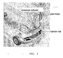
figure 4 shows the installation of the invention for use. - According to the invention, the detergent liquid and gas mixer for cleaning of the gas injectors on explosion engines without dismounting, is made up of a metal container that serves as an expansion chamber with a threaded inlet at the top for the introduction of the detergent liquid.
- The inlet is closed with a threaded cap, the top of which is fitted with a T-connector with a pressure gauge to measure internal pressure and a regulating valve for the introduction of the fuel gas.
- On the outside, on one side of the container there are two L-connectors with a transparent tube column attached that serves as a level indicator for the detergent liquid contained in the container. Inside the container, a tube is attached longitudinally crossing through the bottom. A regulating valve is attached to the external end of the through-tube, the outlet of which is fitted with a transparent tube revealing the quantity of gas and liquid detergent mixture leaving the container.
- In a sideways position and near the bottom of the container, a needle valve is fitted to enable the closing and opening of a calibrated hole in the inside bottom part of the through-tube.
- In order to use the detergent liquid and gas mixer for cleaning of the gas injectors on explosion engines without dismounting according to this invention, it is necessary to proceed as follows:
- 1. The correct measure of the detergent liquid is fed into the inlet, while checking the level of the released liquid on the level indicator.
- 2. The inlet is closed with the threaded cap.
- 3. Using appropriate fixtures, the mixer being described is interposed vertically between the gas pressure reducer of the engine fuel-feeder system and the injectors and solenoid valves to be cleaned; this operation is carried out by first closing the tap of the cylinder taking the gas to the pressure reducer for safety reasons and then attaching the outlet tube of the reducer gas to the regulating valve on the inlet cap of the mixer.
- 4. Appropriate standard-type connectors are then used to attach the transparent tube on the bottom of the mixer to the injectors or solenoid valves to be cleaned.
- 5. The tap on the gas cylinder is opened, the regulating valve on the mixer inlet is opened, and the regulating valve at the outlet on the bottom of the mixer is opened. Doing thus enables the flow of LPG or methane gas to feed the engine inside the mixer that is the subject of this patent.
- The pressure gauge fitted to the threaded cap of the inlet can be used to control the pressure of the gas entering the mixer. At this point, the engine is started up and the outlet of the detergent being used to clean the injectors or solenoid valves is regulated by actuating the needle valve at the bottom of the mixer. The mixture of the fuel gas and the detergent liquid can be varied according to the requirements by actuating the regulating valve on the threaded cap of the inlet, the amount of gas entering the injectors or solenoid valves to be cleaned can be regulated, and by actuating the needle valve at the bottom of the mixer, the amount of detergent liquid used to clean the injectors and solenoid valves can be regulated.
- When the externally fitted level indicator shows that the detergent liquid has been depleted and the cleaning operation has therefore finished, the engine is turned off and for safety the tap of the cylinder taking the gas to the pressure reducer is closed before dismounting the mixer subject to this patent from the gas feed system, in order to reinstate the engine fuel-feeder device.
- It should also be noted that, according to the invention, during cleaning of the injectors or solenoid valves, the engine of the vehicle remains switched on and operational.
- Below is a list of the components used in the production example described and illustrated in this description:
- 1. ALUMINIUM THREADED CAP
- 2 VITON-SEAL CYLINDER GASKET
- 3 ALUMINIUM CYLINDER BODY
- 4 LOWER ALUMINIUM PRESSURE CAP
- 5 INTERNAL GAS OVERFLOW TUBE
- 6 FILTER ELEMENT
- 7 FIXING CLIP WITH SPRING HOOK
- 8 SIDE-
COUPLED PRESSURE GAUGE 1/8 SCALE 0/3 BAR - 9 CYLINDER REDUCTION 1/4 1/8 (*)
- 10 1/4 FEMALE SIDE T-
CONNECTOR 1/4 - 11 FEMALE BALL VALVE FROM 1/4
- 12 SOCKET WITH MALE COUPLING FROM 1/4
- 13 CONICAL MALE L-CONNECTOR FROM 1/8
- 14 CONICAL MALE L-CONNECTOR FROM 1/8
- 15 WHITE RILSAN TUBE 6/4
- 16 REGULATING NEEDLE VALVE
- 17 VITON-SEAL CYLINDER GASKET FOR LOWER CAP
- 18 HEXAGONAL STEEL SCREWS
- 19 CYLINDER NIPPLE 1/4
- 20 FEMALE BALL VALVE FROM 1/4
- 21 STRAIGHT MALE CYLINDER CONNECTOR 1/4
- 22 RILSAN TUBE
- 23 STRAIGHT MALE CYLINDER CONNECTOR 1/4
- 24 REDUCING SLEEVE 1/4 3/8
- 25 HOSE CONNECTION FROM 14 3/8
- 26 WHITE SPIRAL RILSAN TUBE 6/8
- 27 HOSE CONNECTION FROM 14 3/8
- 28 REDUCING
SLEEVE 1/4 3/8 - 29 STRAIGHT
MALE CYLINDER CONNECTOR 1/4 - 30 STRAIGHT
FEMALE CYLINDER CONNECTOR 1/4 - 31 JOINT WITH FEMALE COUPLING FROM 1/4
- 32 JOINT WITH FEMALE COUPLING FROM 1/4
- 33 JOINT WITH MALE COUPLING FROM 1/4
- 34 COPPER WASHERS
- 35 GAS TUBE 14
- 36 STAR CLAMP
- 37 CYLINDER NIPPLE FROM 1/4
- 38 TOOLBOX
(*) Only necessary if the thread of the pressure gauge coupling is from 1/8.
Claims (6)
- Device for cleaning injectors or solenoid valves of gaseous fuel feed systems on explosion engines without dismounting, characterised by the fact that it includes the following combination:- A metal container (1, 3, 4) designed to serve as an expansion chamber, with a threaded inlet at the top for the introduction of the detergent liquid;- A threaded cap to close the inlet, the top of which is fitted with a T-connector (10) with a pressure gauge to measure the internal pressure of the container (3);- A regulating valve (11) designed to control the introduction of fuel gas into the container, which is designed to be connected to the fuel gas feed line;- A transparent tube column (15) serving as a level indicator for the liquid detergent contained in the container (3), which is connected laterally to the outside of the container with two L-connectors (13, 14);- A longitudinal tube (5) fixed to the inside of the container (3), crossing its lower base (4), and with its top open near the upper base (1) of the container (3);- A lower regulating valve (20) connected to the external lower end of the longitudinal tube (5), at the outlet of which a transparent tube is fixed(22) which is used to see the quantity of gas and detergent liquid mixture that is leaving the container, and is designed to be attached to the injectors or solenoid valves being cleaned;- A needle valve (16), fitted sideways and near the lower base (4) of the container (3), designed to enable the closing and opening of a calibrated hole in the lower inside part of the.longitudinal tube (5);said calibrated hole being used to mix said detergent with fuel gas which is fed to the engine while it is operating without stopping its operation.
- Device according to the preceding claim, characterised by the fact that the outlet of the deterrent liquid from the device is regulated by the needle valve (16).
- Device according to claim 1, characterised by the fact that the intake of fuel gas into the device is regulated by the upper valve (11).
- Device according to claim 1, characterised by the fact that the outlet of the gas and liquid detergent mixture from the device is regulated by the lower valve (20).
- Device according to claim 1, characterised by the fact that it is designed to be attached to the tubes of the fuel gas feed system of the explosion engine, between the pressure reducer and the feed of the injectors or solenoid valves.
- Device according to claim 1, characterised by the fact that it is designed to be used while the engine remains turned on and operational.
Priority Applications (1)
| Application Number | Priority Date | Filing Date | Title |
|---|---|---|---|
| PL06832329T PL1963664T3 (en) | 2005-12-16 | 2006-11-21 | Mixer of gaseous fuel and liquid detergent for cleaning gas injectors of combustion engines without the needing of dismount any part. |
Applications Claiming Priority (2)
| Application Number | Priority Date | Filing Date | Title |
|---|---|---|---|
| IT000197A ITTV20050197A1 (en) | 2005-12-16 | 2005-12-16 | GAS MIXER AND CLEANING LIQUID FOR CLEANING WITHOUT DISASSEMBLING GAS INJECTORS MOUNTED ON EIGHT-CYCLE MOTORS. |
| PCT/IT2006/000812 WO2007069287A2 (en) | 2005-12-16 | 2006-11-21 | Mixer of gaseous fuel and liquid detergent for cleaning gas injectors of explosion engines without the needing of dismount any part. |
Publications (2)
| Publication Number | Publication Date |
|---|---|
| EP1963664A2 EP1963664A2 (en) | 2008-09-03 |
| EP1963664B1 true EP1963664B1 (en) | 2010-03-24 |
Family
ID=38013184
Family Applications (1)
| Application Number | Title | Priority Date | Filing Date |
|---|---|---|---|
| EP06832329A Active EP1963664B1 (en) | 2005-12-16 | 2006-11-21 | Mixer of gaseous fuel and liquid detergent for cleaning gas injectors of combustion engines without the needing of dismount any part. |
Country Status (9)
| Country | Link |
|---|---|
| EP (1) | EP1963664B1 (en) |
| AT (1) | ATE462079T1 (en) |
| BR (1) | BRPI0621062A2 (en) |
| DE (1) | DE602006013188D1 (en) |
| ES (1) | ES2342980T3 (en) |
| IT (1) | ITTV20050197A1 (en) |
| PL (1) | PL1963664T3 (en) |
| PT (1) | PT1963664E (en) |
| WO (1) | WO2007069287A2 (en) |
Families Citing this family (2)
| Publication number | Priority date | Publication date | Assignee | Title |
|---|---|---|---|---|
| ITMI20071358A1 (en) * | 2007-07-09 | 2009-01-10 | Autochem Italiana S R L | METHOD AND DEVELOPMENT OF CLEANING OF ALTERNATIVE MOTORS |
| DE102008008125A1 (en) * | 2008-02-08 | 2009-08-13 | Tunap Industrie Chemie Gmbh & Co. Produktions Kg | Method and device for cleaning LPG injection valves |
Family Cites Families (5)
| Publication number | Priority date | Publication date | Assignee | Title |
|---|---|---|---|---|
| US2711725A (en) * | 1953-07-09 | 1955-06-28 | Purolator Products Inc | Apparatus for removal of carbon deposits in internal combustion engines |
| US5516370A (en) * | 1991-02-14 | 1996-05-14 | Karnauchow; Leonid | Can adaptor for fuel system cleaning solvent and method of using same |
| US5257604A (en) * | 1991-05-06 | 1993-11-02 | Wynn Oil Company | Multi-mode engine cleaning fluid application apparatus and method |
| US6000413A (en) * | 1998-09-01 | 1999-12-14 | Innova Electronics Corporation | Fuel injector cleaning system |
| US20050229952A1 (en) * | 2004-04-20 | 2005-10-20 | Bg Products, Inc. | Diesel fuel injector cleaning system and method |
-
2005
- 2005-12-16 IT IT000197A patent/ITTV20050197A1/en unknown
-
2006
- 2006-11-21 ES ES06832329T patent/ES2342980T3/en active Active
- 2006-11-21 AT AT06832329T patent/ATE462079T1/en not_active IP Right Cessation
- 2006-11-21 WO PCT/IT2006/000812 patent/WO2007069287A2/en active Application Filing
- 2006-11-21 BR BRPI0621062-7A patent/BRPI0621062A2/en not_active IP Right Cessation
- 2006-11-21 PL PL06832329T patent/PL1963664T3/en unknown
- 2006-11-21 DE DE602006013188T patent/DE602006013188D1/en active Active
- 2006-11-21 PT PT06832329T patent/PT1963664E/en unknown
- 2006-11-21 EP EP06832329A patent/EP1963664B1/en active Active
Also Published As
| Publication number | Publication date |
|---|---|
| ATE462079T1 (en) | 2010-04-15 |
| PL1963664T3 (en) | 2010-08-31 |
| WO2007069287A3 (en) | 2007-08-02 |
| EP1963664A2 (en) | 2008-09-03 |
| ITTV20050197A1 (en) | 2007-06-17 |
| PT1963664E (en) | 2010-06-18 |
| DE602006013188D1 (en) | 2010-05-06 |
| ES2342980T3 (en) | 2010-07-20 |
| BRPI0621062A2 (en) | 2012-08-07 |
| WO2007069287A2 (en) | 2007-06-21 |
Similar Documents
| Publication | Publication Date | Title |
|---|---|---|
| US20140102415A1 (en) | Fuel system and methods | |
| JPH01301923A (en) | Fuel injector and cleaning device for combustion chamber | |
| ATE380702T1 (en) | CLOSURE DEVICE FOR A FILLING PIPE OF A LIQUID TANK, TANK EQUIPPED WITH SUCH A DEVICE | |
| EP1963664B1 (en) | Mixer of gaseous fuel and liquid detergent for cleaning gas injectors of combustion engines without the needing of dismount any part. | |
| US9016262B2 (en) | Fuel injector connector device and method | |
| AU2007270171B2 (en) | Injector assembly | |
| PL368376A1 (en) | Electronically controlled multi-valve, for lpg fuel tanks | |
| MY144149A (en) | Fuel injection system and fuek injection valve device used in fuel injection system | |
| EP2014902A2 (en) | Method and device for cleaning reciprocating engines | |
| EP2141042A1 (en) | Apparatus for filling an additive or a mixture of additives into a tank of liquefied petroleum gas (LPG) | |
| US7231930B1 (en) | Valve assembly cleaning device | |
| WO2020031027A1 (en) | Integrated manifold for a natural gas-fuelled internal combustion engine | |
| US10077182B2 (en) | Fuel can adapter | |
| KR101054045B1 (en) | Nipple for gas tank connection | |
| EP3126662B1 (en) | Supply system for a monofuel motor vehicle powered with alternative fuel, monofuel motor vehicle powered with alternative fuel and method of adjustment of said supply system | |
| TR199903290A2 (en) | Device for the supply of liquid petroleum gas to internal combustion engines, which includes an isobaric vaporizer and a pressure reducer that then comes into play. | |
| CN203082357U (en) | Water valve | |
| RU2462610C2 (en) | System of sealed connection between tubular sections, namely for sealed connection of tube for supply of fuel gas under high pressure with pressure reducing valve in automobile internal combustion engines | |
| RU97120725A (en) | LIQUID FUEL INPUT SYSTEM | |
| RU2291984C1 (en) | Device for easing starting of engine with gasoline injection | |
| US2582637A (en) | Fuel injector for starting internalcombustion engines | |
| CN201255302Y (en) | Oil and water loosing oil conduit | |
| SU134937A1 (en) | Gas mixing device for carrying out the operation of four-stroke diesel engines without pressurization, for example, type B2-300, according to the normal diesel working process for the gas-liquid (two-phase) diesel process and for the gas process with spark ignition | |
| US1374401A (en) | Priming device | |
| JP2015010562A (en) | Induction system cleaning device of engine |
Legal Events
| Date | Code | Title | Description |
|---|---|---|---|
| PUAI | Public reference made under article 153(3) epc to a published international application that has entered the european phase |
Free format text: ORIGINAL CODE: 0009012 |
|
| 17P | Request for examination filed |
Effective date: 20080714 |
|
| AK | Designated contracting states |
Kind code of ref document: A2 Designated state(s): AT BE BG CH CY CZ DE DK EE ES FI FR GB GR HU IE IS IT LI LT LU LV MC NL PL PT RO SE SI SK TR |
|
| AX | Request for extension of the european patent |
Extension state: AL BA HR MK RS |
|
| GRAP | Despatch of communication of intention to grant a patent |
Free format text: ORIGINAL CODE: EPIDOSNIGR1 |
|
| RIC1 | Information provided on ipc code assigned before grant |
Ipc: F02M 21/02 20060101ALI20090922BHEP Ipc: F02M 65/00 20060101AFI20090922BHEP |
|
| RTI1 | Title (correction) |
Free format text: MIXER OF GASEOUS FUEL AND LIQUID DETERGENT FOR CLEANING GAS INJECTORS OF COMBUSTION ENGINES WITHOUT THE NEEDING OF DISMOUNT ANY PART. |
|
| GRAS | Grant fee paid |
Free format text: ORIGINAL CODE: EPIDOSNIGR3 |
|
| GRAA | (expected) grant |
Free format text: ORIGINAL CODE: 0009210 |
|
| AK | Designated contracting states |
Kind code of ref document: B1 Designated state(s): AT BE BG CH CY CZ DE DK EE ES FI FR GB GR HU IE IS IT LI LT LU LV MC NL PL PT RO SE SI SK TR |
|
| AX | Request for extension of the european patent |
Extension state: AL BA HR MK RS |
|
| REG | Reference to a national code |
Ref country code: GB Ref legal event code: FG4D |
|
| REG | Reference to a national code |
Ref country code: CH Ref legal event code: EP |
|
| REG | Reference to a national code |
Ref country code: IE Ref legal event code: FG4D |
|
| REF | Corresponds to: |
Ref document number: 602006013188 Country of ref document: DE Date of ref document: 20100506 Kind code of ref document: P |
|
| REG | Reference to a national code |
Ref country code: PT Ref legal event code: SC4A Free format text: AVAILABILITY OF NATIONAL TRANSLATION Effective date: 20100611 |
|
| REG | Reference to a national code |
Ref country code: NL Ref legal event code: T3 |
|
| REG | Reference to a national code |
Ref country code: ES Ref legal event code: FG2A Ref document number: 2342980 Country of ref document: ES Kind code of ref document: T3 |
|
| PG25 | Lapsed in a contracting state [announced via postgrant information from national office to epo] |
Ref country code: LT Free format text: LAPSE BECAUSE OF FAILURE TO SUBMIT A TRANSLATION OF THE DESCRIPTION OR TO PAY THE FEE WITHIN THE PRESCRIBED TIME-LIMIT Effective date: 20100324 |
|
| LTIE | Lt: invalidation of european patent or patent extension |
Effective date: 20100324 |
|
| PG25 | Lapsed in a contracting state [announced via postgrant information from national office to epo] |
Ref country code: AT Free format text: LAPSE BECAUSE OF FAILURE TO SUBMIT A TRANSLATION OF THE DESCRIPTION OR TO PAY THE FEE WITHIN THE PRESCRIBED TIME-LIMIT Effective date: 20100324 Ref country code: SI Free format text: LAPSE BECAUSE OF FAILURE TO SUBMIT A TRANSLATION OF THE DESCRIPTION OR TO PAY THE FEE WITHIN THE PRESCRIBED TIME-LIMIT Effective date: 20100324 Ref country code: LV Free format text: LAPSE BECAUSE OF FAILURE TO SUBMIT A TRANSLATION OF THE DESCRIPTION OR TO PAY THE FEE WITHIN THE PRESCRIBED TIME-LIMIT Effective date: 20100324 Ref country code: FI Free format text: LAPSE BECAUSE OF FAILURE TO SUBMIT A TRANSLATION OF THE DESCRIPTION OR TO PAY THE FEE WITHIN THE PRESCRIBED TIME-LIMIT Effective date: 20100324 |
|
| REG | Reference to a national code |
Ref country code: PL Ref legal event code: T3 |
|
| PG25 | Lapsed in a contracting state [announced via postgrant information from national office to epo] |
Ref country code: RO Free format text: LAPSE BECAUSE OF FAILURE TO SUBMIT A TRANSLATION OF THE DESCRIPTION OR TO PAY THE FEE WITHIN THE PRESCRIBED TIME-LIMIT Effective date: 20100324 Ref country code: EE Free format text: LAPSE BECAUSE OF FAILURE TO SUBMIT A TRANSLATION OF THE DESCRIPTION OR TO PAY THE FEE WITHIN THE PRESCRIBED TIME-LIMIT Effective date: 20100324 Ref country code: GR Free format text: LAPSE BECAUSE OF FAILURE TO SUBMIT A TRANSLATION OF THE DESCRIPTION OR TO PAY THE FEE WITHIN THE PRESCRIBED TIME-LIMIT Effective date: 20100625 Ref country code: BE Free format text: LAPSE BECAUSE OF FAILURE TO SUBMIT A TRANSLATION OF THE DESCRIPTION OR TO PAY THE FEE WITHIN THE PRESCRIBED TIME-LIMIT Effective date: 20100324 Ref country code: SE Free format text: LAPSE BECAUSE OF FAILURE TO SUBMIT A TRANSLATION OF THE DESCRIPTION OR TO PAY THE FEE WITHIN THE PRESCRIBED TIME-LIMIT Effective date: 20100324 |
|
| PG25 | Lapsed in a contracting state [announced via postgrant information from national office to epo] |
Ref country code: IS Free format text: LAPSE BECAUSE OF FAILURE TO SUBMIT A TRANSLATION OF THE DESCRIPTION OR TO PAY THE FEE WITHIN THE PRESCRIBED TIME-LIMIT Effective date: 20100724 Ref country code: BG Free format text: LAPSE BECAUSE OF FAILURE TO SUBMIT A TRANSLATION OF THE DESCRIPTION OR TO PAY THE FEE WITHIN THE PRESCRIBED TIME-LIMIT Effective date: 20100624 Ref country code: CZ Free format text: LAPSE BECAUSE OF FAILURE TO SUBMIT A TRANSLATION OF THE DESCRIPTION OR TO PAY THE FEE WITHIN THE PRESCRIBED TIME-LIMIT Effective date: 20100324 Ref country code: SK Free format text: LAPSE BECAUSE OF FAILURE TO SUBMIT A TRANSLATION OF THE DESCRIPTION OR TO PAY THE FEE WITHIN THE PRESCRIBED TIME-LIMIT Effective date: 20100324 |
|
| PLBE | No opposition filed within time limit |
Free format text: ORIGINAL CODE: 0009261 |
|
| STAA | Information on the status of an ep patent application or granted ep patent |
Free format text: STATUS: NO OPPOSITION FILED WITHIN TIME LIMIT |
|
| PG25 | Lapsed in a contracting state [announced via postgrant information from national office to epo] |
Ref country code: DK Free format text: LAPSE BECAUSE OF FAILURE TO SUBMIT A TRANSLATION OF THE DESCRIPTION OR TO PAY THE FEE WITHIN THE PRESCRIBED TIME-LIMIT Effective date: 20100324 |
|
| 26N | No opposition filed |
Effective date: 20101228 |
|
| PG25 | Lapsed in a contracting state [announced via postgrant information from national office to epo] |
Ref country code: MC Free format text: LAPSE BECAUSE OF NON-PAYMENT OF DUE FEES Effective date: 20101130 |
|
| REG | Reference to a national code |
Ref country code: CH Ref legal event code: PL |
|
| PG25 | Lapsed in a contracting state [announced via postgrant information from national office to epo] |
Ref country code: CH Free format text: LAPSE BECAUSE OF NON-PAYMENT OF DUE FEES Effective date: 20101130 Ref country code: LI Free format text: LAPSE BECAUSE OF NON-PAYMENT OF DUE FEES Effective date: 20101130 |
|
| PG25 | Lapsed in a contracting state [announced via postgrant information from national office to epo] |
Ref country code: IE Free format text: LAPSE BECAUSE OF NON-PAYMENT OF DUE FEES Effective date: 20101121 |
|
| PG25 | Lapsed in a contracting state [announced via postgrant information from national office to epo] |
Ref country code: CY Free format text: LAPSE BECAUSE OF FAILURE TO SUBMIT A TRANSLATION OF THE DESCRIPTION OR TO PAY THE FEE WITHIN THE PRESCRIBED TIME-LIMIT Effective date: 20100324 |
|
| PG25 | Lapsed in a contracting state [announced via postgrant information from national office to epo] |
Ref country code: LU Free format text: LAPSE BECAUSE OF NON-PAYMENT OF DUE FEES Effective date: 20101121 Ref country code: HU Free format text: LAPSE BECAUSE OF FAILURE TO SUBMIT A TRANSLATION OF THE DESCRIPTION OR TO PAY THE FEE WITHIN THE PRESCRIBED TIME-LIMIT Effective date: 20100925 |
|
| PG25 | Lapsed in a contracting state [announced via postgrant information from national office to epo] |
Ref country code: TR Free format text: LAPSE BECAUSE OF FAILURE TO SUBMIT A TRANSLATION OF THE DESCRIPTION OR TO PAY THE FEE WITHIN THE PRESCRIBED TIME-LIMIT Effective date: 20100324 |
|
| REG | Reference to a national code |
Ref country code: FR Ref legal event code: PLFP Year of fee payment: 10 |
|
| PGFP | Annual fee paid to national office [announced via postgrant information from national office to epo] |
Ref country code: NL Payment date: 20151123 Year of fee payment: 10 |
|
| REG | Reference to a national code |
Ref country code: FR Ref legal event code: PLFP Year of fee payment: 11 |
|
| REG | Reference to a national code |
Ref country code: NL Ref legal event code: MM Effective date: 20161201 |
|
| PG25 | Lapsed in a contracting state [announced via postgrant information from national office to epo] |
Ref country code: NL Free format text: LAPSE BECAUSE OF NON-PAYMENT OF DUE FEES Effective date: 20161201 |
|
| REG | Reference to a national code |
Ref country code: FR Ref legal event code: PLFP Year of fee payment: 12 |
|
| PGFP | Annual fee paid to national office [announced via postgrant information from national office to epo] |
Ref country code: DE Payment date: 20171117 Year of fee payment: 12 |
|
| PGFP | Annual fee paid to national office [announced via postgrant information from national office to epo] |
Ref country code: GB Payment date: 20171116 Year of fee payment: 12 Ref country code: PT Payment date: 20171109 Year of fee payment: 12 |
|
| PGFP | Annual fee paid to national office [announced via postgrant information from national office to epo] |
Ref country code: TR Payment date: 20181101 Year of fee payment: 10 |
|
| REG | Reference to a national code |
Ref country code: DE Ref legal event code: R119 Ref document number: 602006013188 Country of ref document: DE |
|
| GBPC | Gb: european patent ceased through non-payment of renewal fee |
Effective date: 20181121 |
|
| PG25 | Lapsed in a contracting state [announced via postgrant information from national office to epo] |
Ref country code: PT Free format text: LAPSE BECAUSE OF NON-PAYMENT OF DUE FEES Effective date: 20190521 |
|
| PG25 | Lapsed in a contracting state [announced via postgrant information from national office to epo] |
Ref country code: DE Free format text: LAPSE BECAUSE OF NON-PAYMENT OF DUE FEES Effective date: 20190601 |
|
| PG25 | Lapsed in a contracting state [announced via postgrant information from national office to epo] |
Ref country code: GB Free format text: LAPSE BECAUSE OF NON-PAYMENT OF DUE FEES Effective date: 20181121 |
|
| PGFP | Annual fee paid to national office [announced via postgrant information from national office to epo] |
Ref country code: PL Payment date: 20191104 Year of fee payment: 14 |
|
| PG25 | Lapsed in a contracting state [announced via postgrant information from national office to epo] |
Ref country code: FR Free format text: LAPSE BECAUSE OF NON-PAYMENT OF DUE FEES Effective date: 20191130 |
|
| REG | Reference to a national code |
Ref country code: ES Ref legal event code: FD2A Effective date: 20210528 |
|
| PG25 | Lapsed in a contracting state [announced via postgrant information from national office to epo] |
Ref country code: ES Free format text: LAPSE BECAUSE OF NON-PAYMENT OF DUE FEES Effective date: 20191122 |
|
| PG25 | Lapsed in a contracting state [announced via postgrant information from national office to epo] |
Ref country code: PL Free format text: LAPSE BECAUSE OF NON-PAYMENT OF DUE FEES Effective date: 20201121 |
|
| PGFP | Annual fee paid to national office [announced via postgrant information from national office to epo] |
Ref country code: IT Payment date: 20231024 Year of fee payment: 18 |