EP1963617B1 - Geschlitztes klemmkeilelement für ausdehnbaren packer - Google Patents
Geschlitztes klemmkeilelement für ausdehnbaren packer Download PDFInfo
- Publication number
- EP1963617B1 EP1963617B1 EP06769920A EP06769920A EP1963617B1 EP 1963617 B1 EP1963617 B1 EP 1963617B1 EP 06769920 A EP06769920 A EP 06769920A EP 06769920 A EP06769920 A EP 06769920A EP 1963617 B1 EP1963617 B1 EP 1963617B1
- Authority
- EP
- European Patent Office
- Prior art keywords
- mandrel
- slip
- expansion
- packer
- axial
- Prior art date
- Legal status (The legal status is an assumption and is not a legal conclusion. Google has not performed a legal analysis and makes no representation as to the accuracy of the status listed.)
- Ceased
Links
- 238000007789 sealing Methods 0.000 claims description 16
- 239000012530 fluid Substances 0.000 claims description 14
- 230000004323 axial length Effects 0.000 claims description 6
- 238000000034 method Methods 0.000 description 8
- 238000012856 packing Methods 0.000 description 3
- 229910001104 4140 steel Inorganic materials 0.000 description 2
- 238000004519 manufacturing process Methods 0.000 description 2
- 239000012815 thermoplastic material Substances 0.000 description 2
- 239000004696 Poly ether ether ketone Substances 0.000 description 1
- 229910000831 Steel Inorganic materials 0.000 description 1
- 229920006362 Teflon® Polymers 0.000 description 1
- JUPQTSLXMOCDHR-UHFFFAOYSA-N benzene-1,4-diol;bis(4-fluorophenyl)methanone Chemical compound OC1=CC=C(O)C=C1.C1=CC(F)=CC=C1C(=O)C1=CC=C(F)C=C1 JUPQTSLXMOCDHR-UHFFFAOYSA-N 0.000 description 1
- 238000010276 construction Methods 0.000 description 1
- 230000000593 degrading effect Effects 0.000 description 1
- 239000000463 material Substances 0.000 description 1
- 239000002184 metal Substances 0.000 description 1
- 229920002530 polyetherether ketone Polymers 0.000 description 1
- 238000003825 pressing Methods 0.000 description 1
- 238000000926 separation method Methods 0.000 description 1
- 239000010959 steel Substances 0.000 description 1
- 239000000126 substance Substances 0.000 description 1
- 229920001169 thermoplastic Polymers 0.000 description 1
- 239000004416 thermosoftening plastic Substances 0.000 description 1
Images

Classifications
-
- E—FIXED CONSTRUCTIONS
- E21—EARTH OR ROCK DRILLING; MINING
- E21B—EARTH OR ROCK DRILLING; OBTAINING OIL, GAS, WATER, SOLUBLE OR MELTABLE MATERIALS OR A SLURRY OF MINERALS FROM WELLS
- E21B23/00—Apparatus for displacing, setting, locking, releasing or removing tools, packers or the like in boreholes or wells
- E21B23/06—Apparatus for displacing, setting, locking, releasing or removing tools, packers or the like in boreholes or wells for setting packers
-
- E—FIXED CONSTRUCTIONS
- E21—EARTH OR ROCK DRILLING; MINING
- E21B—EARTH OR ROCK DRILLING; OBTAINING OIL, GAS, WATER, SOLUBLE OR MELTABLE MATERIALS OR A SLURRY OF MINERALS FROM WELLS
- E21B33/00—Sealing or packing boreholes or wells
- E21B33/10—Sealing or packing boreholes or wells in the borehole
- E21B33/12—Packers; Plugs
- E21B33/1208—Packers; Plugs characterised by the construction of the sealing or packing means
- E21B33/1216—Anti-extrusion means, e.g. means to prevent cold flow of rubber packing
-
- E—FIXED CONSTRUCTIONS
- E21—EARTH OR ROCK DRILLING; MINING
- E21B—EARTH OR ROCK DRILLING; OBTAINING OIL, GAS, WATER, SOLUBLE OR MELTABLE MATERIALS OR A SLURRY OF MINERALS FROM WELLS
- E21B33/00—Sealing or packing boreholes or wells
- E21B33/10—Sealing or packing boreholes or wells in the borehole
- E21B33/12—Packers; Plugs
- E21B33/129—Packers; Plugs with mechanical slips for hooking into the casing
- E21B33/1293—Packers; Plugs with mechanical slips for hooking into the casing with means for anchoring against downward and upward movement
Definitions
- the invention relates to a packer device for use within a wellbore according to the preamble of claim 1.
- US 2005/0034876 A1 which is considered as the closest prior art, discloses an expandable packer having a mandrel with an upper thread and a lower thread, wherein an upper slip ring attaches the upper thread and has extending slips, which are fingers of preferably metal separated by slots.
- the purpose of the slots is to decrease resistance to expansion.
- the slips have wickers or some other surface sharpness designed to dig in for a supporting bite into the casing upon expansion of the mandrel.
- US 2003/0213601 A1 discloses a seal assembly for controlling the flow of fluids in an annulus between a continuous tubular and a cased wellbore.
- the seal assembly includes anchor slips and a seal element.
- the seal assembly is actuated by communicating hydraulic fluid to a setting assembly via an operating fluid conduit integral with the tubular.
- the setting assembly axially shifts a pair of slip ramps which radially expands the anchor slips into gripping engagement with the wellbore and radially expands the seal element into sealing engagement with the wellbore.
- US 3,298,440 discloses a packer having a packing element operatively mounted around a mandrel and adapted for expansion into sealing engagement with a wall of a well bore for packing off the annular space between the mandrel and wall, and a slip-expanding member movably mounted on the mandrel adjacent one end of the packing element and having an outer tapered surface converging toward the mandrel, wherein a tubular slip member is formed of a plurality of individual, elongated, spaced-apart, sectorial segments uniformly arranged around the periphery of the slip member, wherein these segments have an inner surface complementarily shaped and adapted to coengage the tapered surface of the slip-expanding member and an outer wall-engaging surface.
- Traditional packers are comprised of an elastomeric sealing element and at least one mechanically set slip.
- a setting tool is run in with the packer to set it.
- the setting can be accomplished hydraulically due to relative movement created by the setting tool when subjected to applied pressure. This relative movement causes the slips to ride up on cones and extend into biting engagement with the surrounding tubular.
- the sealing element is compressed into sealing contact with the surrounding tubular.
- the set can be held by a body lock ring, which would prevent the reversal of the relative movement that caused the packer to be set in the first instance.
- Some packer designs seek to create an engagement of packer element slips or wickers by direct radial expansion of an expansion mandrel that carries slips or wickers. Examples of such expandable packer designs are found in a parent application to this one, U.S. Patent Publication No. US 2005/0028989 A1 . This Publication describes packer devices that are set by radially expanding an outer expansion mandrel in response to fluid pressure from the flowbore.
- a slip mandrel is generally a unitary tubular component having a substantially smooth radially inner surface and an outer radial surface with engagement wickers integrally formed thereupon. The addition of this unitary component will substantially increase the setting force required to expand the expansion mandrel and urge the wickers into biting engagement with the surrounding tubular.
- U.S. Patent No. 6,378,606 issued to Swor et al. shows a barrel slip body having axial slots that divide the slip body into a series of separate barrel slip anchors.
- the slots extend along almost the entire length of the barrel slip body.
- wedge cones are axially moved to cam the slip portions of the barrel slip radially outwardly and into a set position.
- the slip portions move outwardly substantially uniformly along their lengths.
- the type of barrel slip described in the Swor patent would be unsuitable for use with a radially expandable packer that uses a radially expandable expansion mandrel to urge the slip mandrel into setting.
- the forces involved in setting the slip wickers are substantially different with the radially expandable packer than with an axially set one.
- the expansion mandrel expands radially outwardly in a manner that is substantially uniform along the axial length of the slip mandrel.
- a more suitable slip mandrel design is needed for use with radially expandable packer devices.
- the present invention addresses the problems of the prior art.
- the invention provides an improved packer device and slip mandrel design, according to claim 1, that is particularly well suited for use where the packer device has an expansion mandrel that is expanded radially to set the slip mandrel.
- the exemplary slip mandrel includes a generally tubular mandrel body with an inner radial surface that is shaped and sized to adjoin the outer surface of an expansion mandrel.
- the outer radial surface of the slip mandrel presents a number of hardened wickers that are shaped and sized to create a biting engagement with a surrounding tubular.
- the slip mandrel body contains a number of axial slots about its perimeter in a pattern that is particularly suited to the expandable packer design.
- this pattern features axial slots that partially divide the slip mandrel body from either axial end with those beginning proximate the central portion of the expansion mandrel having a greater length than those beginning from the opposite end of the slip mandrel.
- an exemplary packer device in a preferred embodiment, includes a central packer mandrel and a radially surrounding expansion mandrel.
- the expansion mandrel carries two external slip mandrels that are located on either axial side of a fluid sealing element.
- the fluid sealing element is located upon a central portion of the expansion mandrel, which is expected to experience the greatest amount of radial expansion during setting.
- the packer device may be set using any of a number of known methods for radially expanding the expansion mandrel so that the engagement profiles of the slips are brought into engagement with the surrounding tubular.
- Figure 1 is a side, one-quarter cross-sectional view of an exemplary packer assembly constructed in accordance with the present invention.
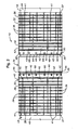
- Figure 2 is an external side view of the packer assembly shown in Figure 1 and illustrating a slotting pattern in accordance with the present invention.
- Figure 3 is an enlarged side, one-quarter cross-sectional view of the fluid seal of the packer assembly and surrounding components.
- Figures 1-3 depict an exemplary packer assembly 10.
- the packer assembly 10 has a generally tubular central packer mandrel 12 that defines an axial flowbore 14 along its length.
- the central axis of the packer mandrel 12 and the packer assembly 10 is shown at 16.
- the central packer mandrel 12 is preferably formed of a very hard, non-malleable material, such as 4140 steel.
- opposite axial ends of the packer mandrel 12 are typically threaded to allow the packer assembly 10 to be incorporated into a string of tubing members and, thereafter, to be disposed within a wellbore for setting.
- An expansion mandrel 18 radially surrounds the packer mandrel 12.
- the expansion mandrel 18 may be formed of 4140 steel also, but is typically of a lesser thickness than the central mandrel 12 so that it can be expanded radially outwardly.
- a hydraulic pressure chamber 20 is defined between the expansion mandrel 18 and the packer mandrel 12.
- the outer radial surface 22 of the expansion mandrel 18 presents a corrugated portion 24 wherein a series of gentle annular ridges 26 are separated by troughs 28.
- Slip mandrels 30, 32 radially surround the expansion mandrel 18.
- the slip mandrels 30, 32 are located on either axial side of a fluid seal element 34, which also surrounds the expansion mandrel 18.
- Each of the slip mandrels 30, 32 includes a slip mandrel body 36 having an inboard axial end 35 and an outboard axial end 37, as well as an outer radial surface 39 that presents a series of radially outwardly protruding wickers 38.
- the "inboard" axial end 35 is the end of the slip mandrel 30 or 32 that lies proximate the central portion 47 of the expansion mandrel 18 and which is expected to undergo the greatest amount of radial expansion during setting.
- the "outboard" axial end 37 will lie furthest away from the central portion 47 and proximate the axial end portions 49 of the expansion mandrel 18.
- the central portion 47 of the expansion mandrel 18 has a lesser thickness than the axial end portions 49 of the expansion mandrel 18. It is noted that, while essentially the entire expansion mandrel 18 will expand radially during setting, there is some non-uniform expansion due to the presence of the radial spaces 51 and the thinner central portion 47.
- the axial end portions 49 of the expansion mandrel 18 will expand outwardly to a greater degree to fill the radial spaces 51. This additional expansion is desirable as it helps to further axially lock the slip mandrels 30, 32 into position upon the body of the expansion mandrel 18.
- the thinner central portion 47 will also tend to expand outwardly to a greater degree than neighboring portions of the expansion mandrel 18.
- Each slip mandrel body 36 is, as shown by Figure 2 , partially separated angularly by inboard axial slots 40 and outboard axial slots 41 to allow the slip mandrels 30, 32 to expand radially.
- the inboard slots 40 begin at the inboard axial end 35 and extend to an intermediate point that is located approximately 90-95% along the axial length of the body of the slip mandrel 30 or 32, as measured from the inboard end 35. Due to the separation of the slip mandrels 30, 32 by slots 40, the inboard axial ends 35 of the slip mandrels 30, 32 are divided into arcuate slip sections 42.
- Outboard slots 41 begin at the outboard end 37 of the body of each slip mandrel 30, 32 and extend approximately 2/3 of the axial length of the body of the slip mandrel 30 or 32, as measured from the outboard end 37. It is currently preferred, as shown in Figure 2 , that there be two of the shorter slots 41 located between each pair of longer slots 40. In testing, this type of slot pattern has proven to be of optimum effectiveness for use with radially expandable packer devices wherein the expansion of the expansion mandrel 18 involves non-uniform expansion forces. During expansion, the outboard slots 41 will be widened due to the additional expansion of the axial end portions 49 of the expansion mandrel 18.
- the wickers 38 are shaped and sized so as to provide a substantial biting engagement with a surrounding tubular when the expansion mandrel 18 is radially expanded.
- the radially inner surface 43 of each slip mandrel 30, 32 is corrugated in a similar manner as the corrugated portion 24 of the expansion mandrel 18 so that the slip mandrels 30, 32 will seat upon the expansion mandrel 18 in a complimentary manner.
- annular retaining rings 44, 46 which are preferably located adjacent the fluid sealing element 34. Additionally, a plurality of retainer segments 48 underlie the retaining rings 44, 46. It is noted that, in Figure 2 , one retaining ring 44 is shown installed while the other retaining ring 46 has been removed to provide a better view of the retainer segments 48.
- Each of the retainer segments 48 is generally rectangular in shape and has a width that approximates the width of the slip sections 42. Additionally, each retainer segment 48 is arcuately curved along its width so that it will lie easily upon the outer surface 22 of the expansion mandrel 18.
- One or more screw holes 50 is disposed through each of the retainer segments 48.
- each retainer segment 48 presents a sloped surface 52 and an axially protruding ledge 54.
- the retaining rings 44, 46 each present a sharpened outer edge 56 and a laterally-protruding leg 58.
- the slip mandrels 30, 32 are secured in place upon the outer surface 22 of the expansion mandrel 18 by affixing securing screws 60 through screw holes 62 in the slip mandrel sections 42 and into the screw holes 50 of the retaining segments 48.
- the leg 58 of the retaining rings 44, 46 overlie the ledges 54 of the retainer segments 48.
- a forward edge portion 64 of the slip sections 42 overlies the leg 58 of the retaining rings 44, 46.
- the legs 58 of the retaining rings 44, 46 will keep the retainer segments 48 within the trough 28 by preventing them from moving radially outwardly or axially upon the surface 22 of the expansion mandrel 18.
- the retaining rings 44, 46 thus serve the function of helping to hold the slip mandrels 30, 32 in place upon the expansion mandrel 18. This securement, together with the use of the complimentary corrugated surfaces, prevents the slip mandrels 30, 32 from moving axially with respect to the expansion mandrel 18 during running in and during the process of setting the packer assembly 10.
- this securement technique does not require the expansion mandrel 18 to be penetrated by a connector, such as a screw, or to have abrupt changes in the geometry of the expansion mandrel 18, either of which might cause the expansion mandrel 18 to fail during setting.
- this securement technique has proven to be quite effective in preventing the slip mandrels 30, 32 from becoming unseated during operation.
- the fluid sealing element 34 is specially formed to provide a seal that can be energized into sealing engagement with a surrounding wellbore tubular and, at the same time, is resistant to chemicals within the wellbore and extreme temperatures.
- the fluid sealing element 34 which is best seen in Figure 3 , includes a seal body 70 with a radially outer sealing surface 72.
- the seal body 70 is preferably fashioned from a thermoplastic material and preferably a chemically inert thermoplastic that is resistant to degrading in extreme temperatures. Suitable thermoplastic materials for use in forming the seal body 70 are TEFLON® and PEEK.
- the radially inner side of the seal body 70 contains three separate annular channels 74. Although three channels are shown, there may be more or fewer than three channels 74.
- Each of the channels 74 houses an elastomeric ring element 76. The presence of the elastomeric ring elements 76 allows the sealing element 34 to be energized into sealing engagement with a surrounding tubular.
- fluid pressure is increased within the hydraulic pressure chamber 20 of the packer assembly 10.
- this is done by increasing fluid pressure from the surface of the well inside the production tubing string within which the packer device 10 is incorporated.
- a ball or plug (not shown) may be dropped into the tubing string to land on a ball seat (not shown) below the packer device 10 within the tubing string.
- Pressure is then built up behind the ball or plug.
- Increased pressure within the flowbore 14 of the packer assembly 10 is transmitted into the hydraulic pressure chamber 20 to expand the expansion mandrel 18 radially outwardly and cause the wickers 38 of the slip mandrels 30, 32 to be set into a surrounding tubular.
- outer tubular and “surrounding tubular” are used herein to designate generally any surrounding cylindrical surface into which the packer device 10 might be set.
- the packer device 10 would be set within a string of steel casing lining the interior of a wellbore.
- a suitably sized packer device 10 could also be set within an inner production tubing string or liner.
- the "surrounding tubular” might be the uncased surface of a section of open hole within a wellbore.
- the setting technique described generally above is merely one example of a technique for radially expanding the expansion mandrel 18 into a set position.
- any of a number of known methods could be used to cause the expansion mandrel 18 to be radially expanded.
- a striker module, power charge, or force intensifier, devices of known construction and operation which are run into the flowbore 16 of the packer device 10 might be used.
- Numerous setting techniques are described in U.S. Patent Publication No. US 2005/0028989 , which is owned by the assignee of the present invention.
Landscapes
- Geology (AREA)
- Life Sciences & Earth Sciences (AREA)
- Engineering & Computer Science (AREA)
- Mining & Mineral Resources (AREA)
- Geochemistry & Mineralogy (AREA)
- Fluid Mechanics (AREA)
- Environmental & Geological Engineering (AREA)
- General Life Sciences & Earth Sciences (AREA)
- Physics & Mathematics (AREA)
- Consolidation Of Soil By Introduction Of Solidifying Substances Into Soil (AREA)
- Piles And Underground Anchors (AREA)
- Earth Drilling (AREA)
- Silver Salt Photography Or Processing Solution Therefor (AREA)
- Electrical Discharge Machining, Electrochemical Machining, And Combined Machining (AREA)
- Extrusion Of Metal (AREA)
- Sealing Devices (AREA)
- Gasket Seals (AREA)
Claims (7)
- Packervorrichtung (10) zur Verwendung innerhalb eines Bohrlochs mit einem zentralen Packerdorn (12),
einem Spreizdorn (18), der den zentralen Packerdorn (12) radial umgibt und der bezüglich des zentralen Packerdoms (12) aufweitbar ist, wobei der Spreizdorn (18) einen Dornkörper aufweist, der zwischen einer radial verringerten, nicht eingestellten Stellung und einer radial vergrößerten, eingestellten Stellung bewegbar ist, und außerdem einen Zentralabschnitt (47) und einen axialen Endabschnitt (49) aufweist,
einem Schlupfdorn (30, 32), der den Spreizdorn (18) radial umgibt und einen Satz von Geflechten (38) aufweist, um einen Beißeingriff mit einer umgebenden Rohrform (C) innerhalb des Bohrlochs zu bilden, wenn der Spreizdorn (18) sich in seiner eingestellten Stellung befindet, wobei der Schlupfdorn (30, 32) ein innen liegendes Ende (35), das in der Nähe des Zentralabschnitts des Spreizdorns (18) liegt, und ein außen liegendes Ende (37) aufweist, das in der Nähe des axialen Endabschnitts (49) des Spreizdorns (18) liegt, und
einer Vielzahl von Axialschlitzen (40, 41), die innerhalb des Schlupfdorns (30, 32) angeordnet sind, um eine radiale Aufweitung des Schlupfdorns (30, 32) während der Aufweitung des Spreizdorns (18) zu ermöglichen,
wobei die Vielzahl von Axialschlitzen (40, 41) einen Satz von innen liegenden Axialschlitzen (40) aufweist, der sich von dem innen liegenden Ende (35) des Schlupfdoms (30, 32) zu einer Zwischenstelle entlang eines Körpers (36) des Schlupfdoms (30, 32) erstreckt,
dadurch gekennzeichnet, dass
die Vielzahl von Axialschlitzen (40, 41) außerdem einen Satz von außen liegenden Axialschlitzen (41) umfasst, der sich von dem außen liegenden Ende (37) des Schlupfdoms (30, 32) zu einer Zwischenstelle entlang des Körpers (36) des Schlupfdoms (30, 32) erstreckt,
wobei die Axialschlitze (40, 41) im Winkel um den Umfang des Schlupfdoms (30, 32) angeordnet sind und es eine Vielzahl außen liegender Axialschlitze (41) gibt, die zwischen jeweils zwei innen liegenden Axialschlitzen (40) angeordnet sind. - Packervorrichtung (10) nach Anspruch 1, bei der die Zwischenstelle von ungefähr 90% bis ungefähr 95% der Axiallänge des Schlupfdorns (30, 32) angeordnet ist, gemessen von dem innen liegenden Ende (35) des Schlupfdorns (30, 32)
- Packervorrichtung (10) nach Anspruch 1, bei der die außen liegenden Axialschlitze (41) eine Axiallänge aufweisen, die kürzer ist als die der innen liegenden Axialschlitze (40).
- Packervorrichtung (10) nach Anspruch 1, bei der zwei außen liegende Axialschlitze (41) zwischen jeweils zwei innen liegenden Axialschlitzen (40) angeordnet sind.
- Packervorrichtung (10) nach Anspruch 3, bei der die außen liegenden Axialschlitze (41) eine Länge haben, die ungefähr zwei Drittel der Axiallänge des Schlupfdoms (30, 32) beträgt.
- Packervorrichtung (10) nach einem der vorhergehenden Ansprüche mit einem Paar der Schlupfdome (30, 32).
- Packervorrichtung nach Anspruch 6, die außerdem ein Fluiddichtelement (34) umfasst, das den Spreizdorn (18) in der Nähe des Zentralabschnitts des Spreizdorns (18) radial umgibt.
Applications Claiming Priority (2)
| Application Number | Priority Date | Filing Date | Title |
|---|---|---|---|
| US11/118,060 US7341110B2 (en) | 2002-04-05 | 2005-04-29 | Slotted slip element for expandable packer |
| PCT/US2006/016315 WO2007027228A1 (en) | 2005-04-29 | 2006-04-28 | Slotted slip element for expandable packer |
Publications (2)
| Publication Number | Publication Date |
|---|---|
| EP1963617A1 EP1963617A1 (de) | 2008-09-03 |
| EP1963617B1 true EP1963617B1 (de) | 2010-01-13 |
Family
ID=36934152
Family Applications (1)
| Application Number | Title | Priority Date | Filing Date |
|---|---|---|---|
| EP06769920A Ceased EP1963617B1 (de) | 2005-04-29 | 2006-04-28 | Geschlitztes klemmkeilelement für ausdehnbaren packer |
Country Status (7)
| Country | Link |
|---|---|
| US (1) | US7341110B2 (de) |
| EP (1) | EP1963617B1 (de) |
| AU (1) | AU2006285396B2 (de) |
| CA (1) | CA2606406C (de) |
| DE (1) | DE602006011787D1 (de) |
| NO (1) | NO339965B1 (de) |
| WO (1) | WO2007027228A1 (de) |
Cited By (2)
| Publication number | Priority date | Publication date | Assignee | Title |
|---|---|---|---|---|
| WO2023014349A1 (en) * | 2021-08-03 | 2023-02-09 | Halliburton Energy Services, Inc. | Slip ring employing radially offset slot |
| GB2622332A (en) * | 2021-08-03 | 2024-03-13 | Halliburton Energy Services Inc | Slip ring employing radially offset slot |
Families Citing this family (30)
| Publication number | Priority date | Publication date | Assignee | Title |
|---|---|---|---|---|
| GB2417043B (en) * | 2004-08-10 | 2009-04-08 | Smith International | Well casing straddle assembly |
| US7730941B2 (en) * | 2005-05-26 | 2010-06-08 | Baker Hughes Incorporated | Expandable tool with enhanced expansion capability |
| US7607476B2 (en) * | 2006-07-07 | 2009-10-27 | Baker Hughes Incorporated | Expandable slip ring |
| US9303477B2 (en) | 2009-04-02 | 2016-04-05 | Michael J. Harris | Methods and apparatus for cementing wells |
| US8453729B2 (en) * | 2009-04-02 | 2013-06-04 | Key Energy Services, Llc | Hydraulic setting assembly |
| US8684096B2 (en) | 2009-04-02 | 2014-04-01 | Key Energy Services, Llc | Anchor assembly and method of installing anchors |
| US8511376B2 (en) * | 2010-07-15 | 2013-08-20 | Dril-Quip, Inc. | Downhole C-ring slip assembly |
| US8893779B2 (en) | 2010-07-19 | 2014-11-25 | Weatherford/Lamb, Inc. | Retrievable slip mechanism for downhole tool |
| AR079760A1 (es) * | 2010-12-28 | 2012-02-15 | Texproil S R L | Dispositivo de empaquetamiento hidraulico recuperable utilizable en pozos de agua, gas y petroleo o fluidos similares |
| AU2012298867B2 (en) * | 2011-08-22 | 2016-09-08 | The Wellboss Company, Llc | Downhole tool and method of use |
| US9212542B2 (en) | 2012-02-23 | 2015-12-15 | Halliburton Energy Services, Inc. | Expandable tubing run through production tubing and into open hole |
| US9157288B2 (en) | 2012-07-19 | 2015-10-13 | General Plastics & Composites, L.P. | Downhole tool system and method related thereto |
| WO2014168608A1 (en) * | 2013-04-09 | 2014-10-16 | Halliburton Energy Services, Inc. | Packer assembly having barrel slips that divert axial loading to the wellbore |
| US8936102B2 (en) * | 2013-04-09 | 2015-01-20 | Halliburton Energy Services, Inc. | Packer assembly having barrel slips that divert axial loading to the wellbore |
| GB2535323B (en) * | 2013-11-29 | 2016-12-07 | Halliburton Energy Services Inc | External slip having expandable slots and a retainer |
| US10655425B2 (en) * | 2015-07-01 | 2020-05-19 | Shell Oil Company | Method and system for sealing an annulur space around an expanded well tubular |
| US10704355B2 (en) | 2016-01-06 | 2020-07-07 | Baker Hughes, A Ge Company, Llc | Slotted anti-extrusion ring assembly |
| US10526864B2 (en) | 2017-04-13 | 2020-01-07 | Baker Hughes, A Ge Company, Llc | Seal backup, seal system and wellbore system |
| US10260310B2 (en) * | 2017-07-10 | 2019-04-16 | Baker Hughes, A Ge Company, Llc | High temperature and pressure packer |
| US10370935B2 (en) | 2017-07-14 | 2019-08-06 | Baker Hughes, A Ge Company, Llc | Packer assembly including a support ring |
| US10689942B2 (en) | 2017-09-11 | 2020-06-23 | Baker Hughes, A Ge Company, Llc | Multi-layer packer backup ring with closed extrusion gaps |
| US10677014B2 (en) | 2017-09-11 | 2020-06-09 | Baker Hughes, A Ge Company, Llc | Multi-layer backup ring including interlock members |
| US10907438B2 (en) | 2017-09-11 | 2021-02-02 | Baker Hughes, A Ge Company, Llc | Multi-layer backup ring |
| US10907437B2 (en) | 2019-03-28 | 2021-02-02 | Baker Hughes Oilfield Operations Llc | Multi-layer backup ring |
| US11098542B2 (en) | 2018-11-19 | 2021-08-24 | Baker Hughes, A Ge Company, Llc | Anchor and method for making |
| US11142978B2 (en) | 2019-12-12 | 2021-10-12 | Baker Hughes Oilfield Operations Llc | Packer assembly including an interlock feature |
| US11988076B2 (en) | 2022-04-08 | 2024-05-21 | Baker Hughes Oilfield Operations Llc | Method for assembling a liner system |
| US20230323745A1 (en) * | 2022-04-08 | 2023-10-12 | Baker Hughes Oilfield Operations Llc | Liner system and method |
| US11898423B2 (en) * | 2022-04-08 | 2024-02-13 | Baker Hughes Oilfield Operations | Liner system and method |
| CN117988761B (zh) * | 2024-04-03 | 2024-06-25 | 东北石油大学 | 可回收式承压堵漏试验辅助工具 |
Family Cites Families (16)
| Publication number | Priority date | Publication date | Assignee | Title |
|---|---|---|---|---|
| US2373005A (en) | 1941-08-19 | 1945-04-03 | Baker Oil Tools Inc | Retrievable well packer |
| US3298440A (en) | 1965-10-11 | 1967-01-17 | Schlumberger Well Surv Corp | Non-retrievable bridge plug |
| US3318385A (en) | 1966-04-12 | 1967-05-09 | Martin B Conrad | Anchor device for well tools |
| US5884699A (en) | 1996-02-26 | 1999-03-23 | Halliburton Energy Services, Inc. | Retrievable torque-through packer having high strength and reduced cross-sectional area |
| US5701954A (en) | 1996-03-06 | 1997-12-30 | Halliburton Energy Services, Inc. | High temperature, high pressure retrievable packer |
| US6536520B1 (en) | 2000-04-17 | 2003-03-25 | Weatherford/Lamb, Inc. | Top drive casing system |
| US6598677B1 (en) * | 1999-05-20 | 2003-07-29 | Baker Hughes Incorporated | Hanging liners by pipe expansion |
| GB9920936D0 (en) * | 1999-09-06 | 1999-11-10 | E2 Tech Ltd | Apparatus for and a method of anchoring an expandable conduit |
| CA2329388C (en) * | 1999-12-22 | 2008-03-18 | Smith International, Inc. | Apparatus and method for packing or anchoring an inner tubular within a casing |
| US6446717B1 (en) * | 2000-06-01 | 2002-09-10 | Weatherford/Lamb, Inc. | Core-containing sealing assembly |
| US6378606B1 (en) | 2000-07-11 | 2002-04-30 | Halliburton Energy Services, Inc. | High temperature high pressure retrievable packer with barrel slip |
| US20030042028A1 (en) * | 2001-09-05 | 2003-03-06 | Weatherford/Lamb, Inc. | High pressure high temperature packer system |
| US7661470B2 (en) | 2001-12-20 | 2010-02-16 | Baker Hughes Incorporated | Expandable packer with anchoring feature |
| US7051805B2 (en) * | 2001-12-20 | 2006-05-30 | Baker Hughes Incorporated | Expandable packer with anchoring feature |
| US7017669B2 (en) * | 2002-05-06 | 2006-03-28 | Weatherford/Lamb, Inc. | Methods and apparatus for expanding tubulars |
| US6808024B2 (en) | 2002-05-20 | 2004-10-26 | Halliburton Energy Services, Inc. | Downhole seal assembly and method for use of same |
-
2005
- 2005-04-29 US US11/118,060 patent/US7341110B2/en not_active Expired - Lifetime
-
2006
- 2006-04-28 CA CA2606406A patent/CA2606406C/en not_active Expired - Fee Related
- 2006-04-28 WO PCT/US2006/016315 patent/WO2007027228A1/en not_active Ceased
- 2006-04-28 DE DE602006011787T patent/DE602006011787D1/de active Active
- 2006-04-28 EP EP06769920A patent/EP1963617B1/de not_active Ceased
- 2006-04-28 AU AU2006285396A patent/AU2006285396B2/en not_active Ceased
-
2007
- 2007-11-06 NO NO20075638A patent/NO339965B1/no not_active IP Right Cessation
Cited By (2)
| Publication number | Priority date | Publication date | Assignee | Title |
|---|---|---|---|---|
| WO2023014349A1 (en) * | 2021-08-03 | 2023-02-09 | Halliburton Energy Services, Inc. | Slip ring employing radially offset slot |
| GB2622332A (en) * | 2021-08-03 | 2024-03-13 | Halliburton Energy Services Inc | Slip ring employing radially offset slot |
Also Published As
| Publication number | Publication date |
|---|---|
| NO339965B1 (no) | 2017-02-20 |
| NO20075638L (no) | 2007-11-29 |
| US7341110B2 (en) | 2008-03-11 |
| CA2606406A1 (en) | 2007-03-08 |
| CA2606406C (en) | 2011-02-15 |
| AU2006285396A1 (en) | 2007-03-08 |
| US20050189120A1 (en) | 2005-09-01 |
| EP1963617A1 (de) | 2008-09-03 |
| DE602006011787D1 (de) | 2010-03-04 |
| WO2007027228A1 (en) | 2007-03-08 |
| AU2006285396B2 (en) | 2011-01-06 |
Similar Documents
| Publication | Publication Date | Title |
|---|---|---|
| EP1963617B1 (de) | Geschlitztes klemmkeilelement für ausdehnbaren packer | |
| AU2011200481B2 (en) | Expandable packer with mounted exterior slips and seal | |
| US8469088B2 (en) | Drillable bridge plug for high pressure and high temperature environments | |
| US6827150B2 (en) | High expansion packer | |
| CA2795798C (en) | High pressure and high temperature ball seat | |
| US6513600B2 (en) | Apparatus and method for packing or anchoring an inner tubular within a casing | |
| CA2629591C (en) | Permanent anchoring device | |
| US20080190600A1 (en) | Drillable bridge plug | |
| CA2704701A1 (en) | Composite downhole tool with reduced slip volume | |
| CA2787282C (en) | Connector for mounting screen to base pipe without welding or swaging | |
| US20030047880A1 (en) | Seal and method | |
| CA2648116A1 (en) | Drillable bridge plug | |
| CN112601875A (zh) | 抗挤压组件和包括该抗挤压组件的密封系统 |
Legal Events
| Date | Code | Title | Description |
|---|---|---|---|
| PUAI | Public reference made under article 153(3) epc to a published international application that has entered the european phase |
Free format text: ORIGINAL CODE: 0009012 |
|
| 17P | Request for examination filed |
Effective date: 20071113 |
|
| AK | Designated contracting states |
Kind code of ref document: A1 Designated state(s): DE GB NL |
|
| RBV | Designated contracting states (corrected) |
Designated state(s): DE GB NL |
|
| 17Q | First examination report despatched |
Effective date: 20090109 |
|
| GRAP | Despatch of communication of intention to grant a patent |
Free format text: ORIGINAL CODE: EPIDOSNIGR1 |
|
| DAX | Request for extension of the european patent (deleted) | ||
| GRAS | Grant fee paid |
Free format text: ORIGINAL CODE: EPIDOSNIGR3 |
|
| GRAA | (expected) grant |
Free format text: ORIGINAL CODE: 0009210 |
|
| AK | Designated contracting states |
Kind code of ref document: B1 Designated state(s): DE GB NL |
|
| REG | Reference to a national code |
Ref country code: GB Ref legal event code: FG4D |
|
| REF | Corresponds to: |
Ref document number: 602006011787 Country of ref document: DE Date of ref document: 20100304 Kind code of ref document: P |
|
| REG | Reference to a national code |
Ref country code: NL Ref legal event code: T3 |
|
| PLBE | No opposition filed within time limit |
Free format text: ORIGINAL CODE: 0009261 |
|
| STAA | Information on the status of an ep patent application or granted ep patent |
Free format text: STATUS: NO OPPOSITION FILED WITHIN TIME LIMIT |
|
| 26N | No opposition filed |
Effective date: 20101014 |
|
| PGFP | Annual fee paid to national office [announced via postgrant information from national office to epo] |
Ref country code: GB Payment date: 20200323 Year of fee payment: 15 Ref country code: NL Payment date: 20200319 Year of fee payment: 15 |
|
| PGFP | Annual fee paid to national office [announced via postgrant information from national office to epo] |
Ref country code: DE Payment date: 20200319 Year of fee payment: 15 |
|
| REG | Reference to a national code |
Ref country code: DE Ref legal event code: R119 Ref document number: 602006011787 Country of ref document: DE |
|
| REG | Reference to a national code |
Ref country code: NL Ref legal event code: MM Effective date: 20210501 |
|
| GBPC | Gb: european patent ceased through non-payment of renewal fee |
Effective date: 20210428 |
|
| PG25 | Lapsed in a contracting state [announced via postgrant information from national office to epo] |
Ref country code: GB Free format text: LAPSE BECAUSE OF NON-PAYMENT OF DUE FEES Effective date: 20210428 Ref country code: DE Free format text: LAPSE BECAUSE OF NON-PAYMENT OF DUE FEES Effective date: 20211103 |
|
| PG25 | Lapsed in a contracting state [announced via postgrant information from national office to epo] |
Ref country code: NL Free format text: LAPSE BECAUSE OF NON-PAYMENT OF DUE FEES Effective date: 20210501 |