EP1963166B1 - Kojenanordnung mit trennvorrichtung - Google Patents
Kojenanordnung mit trennvorrichtung Download PDFInfo
- Publication number
- EP1963166B1 EP1963166B1 EP05816442A EP05816442A EP1963166B1 EP 1963166 B1 EP1963166 B1 EP 1963166B1 EP 05816442 A EP05816442 A EP 05816442A EP 05816442 A EP05816442 A EP 05816442A EP 1963166 B1 EP1963166 B1 EP 1963166B1
- Authority
- EP
- European Patent Office
- Prior art keywords
- bunk
- wall
- partition wall
- under
- roll
- Prior art date
- Legal status (The legal status is an assumption and is not a legal conclusion. Google has not performed a legal analysis and makes no representation as to the accuracy of the status listed.)
- Expired - Lifetime
Links
Images


Classifications
-
- B—PERFORMING OPERATIONS; TRANSPORTING
- B60—VEHICLES IN GENERAL
- B60P—VEHICLES ADAPTED FOR LOAD TRANSPORTATION OR TO TRANSPORT, TO CARRY, OR TO COMPRISE SPECIAL LOADS OR OBJECTS
- B60P3/00—Vehicles adapted to transport, to carry or to comprise special loads or objects
- B60P3/32—Vehicles adapted to transport, to carry or to comprise special loads or objects comprising living accommodation for people, e.g. caravans, camping, or like vehicles
- B60P3/36—Auxiliary arrangements; Arrangements of living accommodation; Details
- B60P3/38—Sleeping arrangements, e.g. living or sleeping accommodation on the roof of the vehicle
-
- B—PERFORMING OPERATIONS; TRANSPORTING
- B62—LAND VEHICLES FOR TRAVELLING OTHERWISE THAN ON RAILS
- B62D—MOTOR VEHICLES; TRAILERS
- B62D33/00—Superstructures for load-carrying vehicles
- B62D33/06—Drivers' cabs
- B62D33/0612—Cabins with living accommodation, especially for long distance road vehicles, i.e. sleeping, cooking, or other facilities
-
- B—PERFORMING OPERATIONS; TRANSPORTING
- B60—VEHICLES IN GENERAL
- B60R—VEHICLES, VEHICLE FITTINGS, OR VEHICLE PARTS, NOT OTHERWISE PROVIDED FOR
- B60R21/00—Arrangements or fittings on vehicles for protecting or preventing injuries to occupants or pedestrians in case of accidents or other traffic risks
- B60R21/02—Occupant safety arrangements or fittings, e.g. crash pads
- B60R21/06—Safety nets, transparent sheets, curtains, or the like, e.g. between occupants and glass
Definitions
- the invention relates to a bunk arrangement comprising a partition device, especially for a sleeping or storing compartment in a vehicle, especially a truck or a bus.
- the invention further relates to a vehicle cabin comprising such a bunk arrangement.
- the cabin especially of a truck or a bus is usually equipped with at least one bunk arrangement or sleeping compartment in which the driver or an assistant driver can rest or sleep during a journey so that stops on a journey can be kept at a minimum and the driver and the assistant driver need not to leave the vehicle in order to sleep over night.
- bunk arrangement or sleeping compartment can usually be used for storing objects or articles.
- a partition device delimiting the bunk arrangement against other areas of the cabin in order to improve the comfort for a person who is resting on the bunk or in order to avoid that stored objects or articles fall down from the bunk arrangement and hurt the driver or the assistant driver during driving.
- EP 1 069 031 discloses a bunk arrangement which comprises a bunk with a free edge with substantially vertically extending safety belts, which are attached to the ceiling of a cabin, and a safety net which is guided and locked by means of a horizontal net rod along the safety belts. Furthermore, at a free edge of the bunk a cartridge is provided enclosing a spring biased shaft for rolling up the safety net when releasing the same for shifting it into its downward position.
- EP 1 147 946 discloses a safety net arrangement for a bunk in which the safety net is provided at its free (forward) end with a net tube with attachments for suspending the net in the cabin.
- Net belts which are fastened to the net tube and the net extend under the bunk and are attached at the back of the wall of the cabin.
- elastic means are provided at the backward end of the net for withdrawing it under the bunk when the net is released from its suspension.
- US6367839 discloses a bunk arrangement with a partition wall and a strap retraction device.
- An object underling the invention is to provide a bunk arrangement according to the introductory part above which comprises a partition device and which can be manufactured and assembled in a quick and easy manner.
- a bunk arrangement comprising a partition device shall be provided, which can be manually operated in a quick and simple way and is reliable in use.
- a bunk arrangement comprising a partition device is provided with a partition wall with a free upper and a lower edge, and a retracting device comprising an actuation means, mounted within or under a bunk of the bunk arrangement for drawing the partition wall at least partly into or under the bunk when the partition wall is released from a suspension.
- the bank arrangement is characterized according to appended claim 1.
- Figure 1 shows a view into the rear part of a cabin having a back wall 3 and a ceiling 4 at which a luggage compartment 2 is mounted.
- a bunk arrangement or sleeping compartment comprising a sleeper berth or bunk 1 is provided for the driver and / or the assistant driver, respectively, for resting or sleeping during a journey or for storing objects or articles.
- the bunk 1 is fastened with a first longitudinal edge at the back wall 3 of the cabin.
- the bunk arrangement is provided with a partition device comprising a partition wall 10 (or separation or safety wall) which preferably extends from the opposite and free second longitudinal edge of the bunk 1 upwardly and is guided and held by means of holding and guiding means preferably in the form of a first and a second belt 11, 12.
- a partition wall 10 or separation or safety wall
- FIG. 2 which is a side view from the left in Figure 1
- the belts 11, 12 are attached according to a first variation of the first embodiment with their first upper ends at the luggage compartment 2.
- the wall 10 can be manufactured from one or more of a plurality of different materials in dependence on the desired properties and functions to be obtained. If for example the wall 10 is provided for hiding objects or articles which are stored on the bunk 1 and / or for keeping the compartment behind the wall 10 dark, the material is preferably opaque. For obtaining a fire protection, for preventing that a person or objects which are lying on the bunk 1 can fall down from the bunk 1 in case of an emergency brake or a collision, and / or for other functions and purposes, the material has to be chosen primarily with respect to an appropriate strength.
- the wall 10 is manufactured for example from a polyester fabric with a thickness of between about 0.7 mm and about 1.2 mm which is usually strong enough for most of the above functions and purposes. Furthermore, such a polyester fabric is easy to clean as well.
- the wall 10 comprises a plurality of wall elements 113.
- the wall 10 is provided substantially in the form of a jalousie with a plurality of longitudinal elements 113 which extend along the length of the wall 10 and which provide a zigzag form in the direction of the height of the wall 10.
- the belts 11, 12 are guided through slits within the elements of the wall 10 so that when shifting the wall 10 down, the wall elements 113 are folded together in a zigzag manner.
- the slits within the elements 113 have a corresponding length so that the wall 10 can be pulled up (i.e. extended) and shifted down as well.
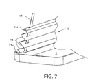
- the longitudinal elements 113 can be swivelling linked together as especially indicated in Figure 7 , or the elements 113 are single elements as in case of a usual jalousie.
- An advantage of such a wall 10 is that it can be used as well to replace a usual curtain which is provided for dividing a known partition device from other parts of a cabin.
- the free second edge of the bunk 1 is provided with a receptacle preferably in the form of a cassette 13 with a substantially rectangular cross section which is indicated in Figure 2 .
- the partition wall 10 can be retracted by folding it into the receptacle 13 and it can be extended by defolding or pulling it out of the receptacle 13.
- the belts 11, 12 are attached with their second lower ends at the foot of the partition wall 10 and especially within the receptacle 13.
- the strengths of the attachments of the belts 11, 12 at the luggage compartment 2 and in the receptacle 13, as well as the strengths of the belts 11, 12 themselves are dimensioned such that they fulfill the requirements for achieving the function of safety belts for preventing that a person or objects which are lying on the bunk 1 can fall down in case of an emergency brake or a collision.
- the upper free end of the wall 10 is provided with a tube or rod 114 by which the wall 10 can be pulled up (and down) by hand along the belts 11, 12 until reaching the luggage compartment 2 as shown in Figure 2 , and by which the wall 10 can be fixed in this or in any intermediate position between the receptacle 13 and the luggage compartment 2 by means of clamping devices (not shown) which are effective between the tube or rod 114 and the belts 11, 12.
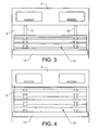
- Figure 3 shows a front view onto the wall 10 and the luggage compartment 2.
- the wall 10 is drawn partly out of the receptacle 13 up to an intermediate position at about a half of the height between the receptacle 13 and the luggage compartment 2.
- the belts 11, 12 are shown in this Figure which are again attached with one end within the receptacle 13 and with the other end at the luggage compartment 2.
- Figure 4 shows the same view as in Figure 3 , however, the wall 10 is pulled up to the luggage compartment 2 so that the bunk arrangement behind the wall 10 is closed against the front part of the cabin.
- FIG. 5 shows a schematic three-dimensional view into the rear part of a cabin of a truck or bus with a bunk arrangement or sleeping compartment comprising a partition device with a partition wall 10 (or separation or safety wall) according to a second variation of the first embodiment of the invention.
- the bunk arrangement again comprises a bunk 1 which is fastened with a first longitudinal edge at a back wall 3 of the cabin and which comprises at the opposite free second longitudinal edge a receptacle 13 in the form of a cassette for enclosing the elements 113 of the wall 10 which can be pulled out of the receptacle 13 and fixed at holding and guiding belts 11, 12 as explained above.
- the belts 11, 12 are attached with their first upper ends at fastening means 111, 112 at the ceiling 4 of the cabin. Consequently, the height of the wall 10 is preferably dimensioned such that it can be pulled up to the ceiling 4 so that the bunk arrangement can be closed.
- the side view according to Figure 6 from the left side in Figure 5 shows the wall 10 pulled up into an intermediate position between the receptacle 13 and the ceiling 4.
- the belts 11, 12 are preferably provided as well for holding and carrying the free second longitudinal edge of the bunk 1 and not only as safety belts and for holding and guiding the wall 10.
- only one or more than two belts can be provided in dependence on their strengths and the load effected by the bunk 1.
- the positions of the belts along the length of the wall 10 are substantially selected such that a person can get onto the bunk 1 in a comfortable manner.
- Figure 7 shows a more detailed view of the right side end portion of the bunk 1 (in which a mattress has been removed) and the wall 10 together with the second belt 12.
- the receptacle 13 is formed at the free second longitudinal edge of the bunk 1 with a substantially U-shaped cross-section.
- this Figure shows in more details the wall 10 comprising a plurality of longitudinal elements 113 which when shifting down the wall 10 are folded together into the receptacle 13.
- the opposite upper edge of the wall 10 is provided with the tube or rod 114 which provides a termination of the wall 10 and makes handling of the wall 10 easier, especially when pulling it up and shifting it down.
- This tube 114 preferably also comprises clamping means for fixing the wall in an intermediate position at the belts 11, 12.
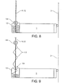
- Figure 8 shows a side view from the right in Figure 1 or 5 in which the back wall 3 of the cabin, the bunk 1 with the receptacle 13 at the free second longitudinal edge of the bunk 1 and the belts 11, 12 are indicated.
- the wall 10 is shifted into its down most position in which the elements 113 of the wall 10 are folded above each other and are enclosed entirely within the receptacle 13.
- the tube or rod 114 which terminates the wall 10 at its upper edge is positioned on the opening of the receptacle 13 so that it closes the same.
- the upper surface of the receptacle 13 comprising the opening for receiving the elements 113 is provided with a groove 131 (see Figure 9 ) running along its length which is formed to receive at least a part of the rod or tube 114 so that it can lie in it and closes the opening when the wall 10 has been shifted into its retracted state.
- Figure 9 again shows the side view of Figure 8 in which the wall 10 has been pulled out of the receptacle 13 partly so that some of the elements 113 of the wall 10 are de-folded and some of the elements 113 are still enclosed within the receptacle 13.
- the rod or tube 114 is preferably provided to fix the wall 10 in a desired position by means of clamping means which are effective between the rod or tube 113 and the belts 11, 12.
- Figures 10 to 13 show a second embodiment of the invention in three variations in which instead of the receptacle 13 the partition wall 10 is retracted into a space under or within the bunk 1.
- This embodiment is especially provided for a wall 10 in the form of e. g. a net or a fabric or any other material which is flexible or can be rolled, curved or bent, or is suitable in another way, for being drawn into or under the bunk 1.
- Figure 10 shows a plan view into the space within (or under) a bunk 1.
- the wall 10 is terminated at its upper free edge with a first tube or rod 114 as described above with respect to the first embodiment.
- this second embodiment of the partition device does not comprise any belts 11, 12 or other guiding means for the partition wall 10.
- the first tube or rod 114 is provided preferably for being hooked into a related upper attachment or suspension at or above the bunk arrangement.
- the opposite lower edge of the wall 10 is drawn into or under a bunk 1 of the bunk arrangement by means of a retracting device 23, 24 comprising an actuation means, which is mounted within or under the bunk 1 and is connected with the lower edge of the partition wall 10 for drawing the same at least partly into or under the bunk 1 when the wall 10 is released from its suspension.
- the wall 10 is provided at its opposite lower edge which lies within or under the bunk, with a second tube or rod 115a at which a wire or line 23 is attached.
- This wire or line 23 is wound on a turning roll 24 which is actuated by a spiral spring (not shown) and which is rotatably mounted at the downside of the bunk or between a lower part 22 and an upper part 21 of the bunk.
- the roll 24 is driven by the spring force so that the wire or line 23 is turned onto the roll 24 and the wall 10 is drawn into the space within or under the bunk 1.
- Figure 11 shows a plan view into the space within (or under) a bunk 1 of a second variation of the second embodiment.
- the same parts as in Figure 10 are again denoted with the same reference signs.
- the wall 10 is again provided at its upper free edge with a first tube or rod 114 as described above.
- the wall 10 is provided at its opposite lower edge lying within or under the bunk 1 with a second tube or rod 115b which is a hollow element so that a wire or line 23 for retracting the wall 10 can be guided through the tube or rod 115b.
- a first end of the wire or line 23 is attached within or under the bunk at its inner or back side.
- the wire or line 23 runs through the second tube or rod 115b and is guided around a spring biased roll 24 which is again driven by the force of a spiral spring (not shown) and is rotatably mounted under the bunk or between a lower part 22 and an upper part 21 of the bunk 1 as described above and indicated in Figure 10 .
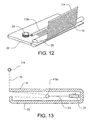
- Figure 12 shows a three-dimensional view into the space within a bunk 1 (the upper part 21 being removed) in which the roll 24 comprising the spiral spring, and the second hollow tube or rod 115b are indicated together with the wall 10 which comprises at its upper free edge the first tube or rod 114.
- the wall 10 is guided out of the space within the bunk 1 around a longitudinal cylinder 25 which extends substantially along the free second longitudinal edge of the bunk 1.
- Figure 13 shows a third variation of the second embodiment in a cross-section through a bunk 1 having an upper part 21 and a lower part 22 between which the space within the bunk 1 is delimited for retracting the partition wall 10 (which is again preferably a net).
- the wall 10 is drawn through an opening along the free second longitudinal edge of the bunk 1.
- the roll 24 is rotatably mounted within the space of the bunk 1 in the region of its first longitudinal edge and again driven by the force of a spiral spring.
- this third variation the wall 10 is attached with its lower edge at the lower part 22 of the bunk 1, in the region of the free second longitudinal edge of the bunk 1. From there, the wall 10 is guided over a tube or rod 115c to the outside of the bunk.
- the tube or rod 115c itself is drawn by means of a wire or line 23 and an actuated roll 24 as described with respect to the second variation according to Figures 11 and 12 .
- This third variation is especially advantageous in case of a bunk 1 with a small width in relation to a wall 10 in the form of a fabric or net with a large height, or generally in case of a wall 10 having a large height.
- the roll 24 according to the second embodiment can be actuated or driven for drawing the wall 10 into or under the bunk 1 as well by means of an electromotor or another actuation means which instead of a spiral spring turns the roll 24.
Landscapes
- Engineering & Computer Science (AREA)
- Transportation (AREA)
- Mechanical Engineering (AREA)
- Public Health (AREA)
- Combustion & Propulsion (AREA)
- Health & Medical Sciences (AREA)
- Chemical & Material Sciences (AREA)
- Vehicle Step Arrangements And Article Storage (AREA)
- Details Of Rigid Or Semi-Rigid Containers (AREA)
- Automatic Cycles, And Cycles In General (AREA)
- Solid Fuels And Fuel-Associated Substances (AREA)
- Cell Separators (AREA)
- Refuse Collection And Transfer (AREA)
- Vehicle Waterproofing, Decoration, And Sanitation Devices (AREA)
Claims (6)
- Kojenanordnung, die eine Kojentrennvorrichtung umfasst, mit:- einer Trennwand (10) mit einem freien oberen und einem unteren Rand,und- einer Rückzugsvorrichtung (23, 24), die eine Betätigungseinrichtung umfasst, die innerhalb oder unterhalb der Koje (1) der Kojenanordnung angeordnet ist, um die Trennwand (10) wenigstens teilweise in oder unter die Koje (1) zu ziehen, wenn die Trennwand (10) von einer Aufhängung freigegeben wird, wobei die Rückzugsvorrichtung (23, 24) eine Rolle (24) umfasst, die in oder unter der Koje (1) betätigbar und drehbar gelagert ist, um einen Draht oder eine Leine (23) aufzuwickeln, der bzw. die mit einem Ende an der Koje (1) angebracht ist und die durch ein hohles Rohr oder eine hohle Stange (115c) zu der Rolle (24) geführt ist, die an dem unteren Rand der Trennwand (10) vorgesehen ist, um die Trennwand (10) wenigstens teilweise in oder unter die Koje (1) zu ziehen, dadurch gekennzeichnet, dass die Rückzugsvorrichtung (23, 24) eine Rolle (24) umfasst, die in oder unter der Koje für ein Aufwickeln eines Drahtes oder einer Leine (23) betätigt wird und drehbar gelagert ist, der bzw. die mit einem Ende an der Koje (1) befestigt ist und die durch ein hohles Rohr oder eine hohle Stange (115c) geführt ist, und dass die Trennwand (10) mit ihrem unteren Rand an der Koje (1) befestigt ist und um das hohle Rohr oder die hohle Stange (115c) zu der Außenseite der Koje (1) geführt ist, um die Trennwand (10) wenigstens teilweise in oder unter die Koje (1) zu ziehen.
- Kojenanordnung nach Anspruch 1, bei der die Trennwand (10) aus einem Netz oder einem Stoff oder einem Material hergestellt ist, das flexibel ist und gerollt, gekrümmt oder gebogen werden kann, um in oder unter die Koje (1) gezogen zu werden.
- Kojenanordnung nach Anspruch 1, bei der die Betätigungseinrichtung eine Spiralfeder umfasst, die innerhalb der Rolle (24) enthalten ist und für ein Drehen der Rolle (24) vorgesehen ist.
- Kojenanordnung nach Anspruch 1, bei der die Betätigungseinrichtung einen Elektromotor umfasst, der innerhalb der Rolle (24) enthalten ist und für ein Drehen der Rolle (24) vorgesehen ist.
- Kojenanordnung nach Anspruch 1, bei der eine Stange oder ein Rohr (114) an dem oberen Rand der Trennwand (10) für eine Befestigung der Wand in einem ausgefahrenen Zustand an einer oberen Aufhängung vorgesehen ist.
- Fahrzeugkabine mit einer Kojenanordnung nach Anspruch 1.
Applications Claiming Priority (1)
| Application Number | Priority Date | Filing Date | Title |
|---|---|---|---|
| PCT/SE2005/001921 WO2007069947A1 (en) | 2005-12-13 | 2005-12-13 | Bunk arrangement with partition device |
Publications (3)
| Publication Number | Publication Date |
|---|---|
| EP1963166A1 EP1963166A1 (de) | 2008-09-03 |
| EP1963166A4 EP1963166A4 (de) | 2010-03-31 |
| EP1963166B1 true EP1963166B1 (de) | 2011-03-16 |
Family
ID=38163167
Family Applications (1)
| Application Number | Title | Priority Date | Filing Date |
|---|---|---|---|
| EP05816442A Expired - Lifetime EP1963166B1 (de) | 2005-12-13 | 2005-12-13 | Kojenanordnung mit trennvorrichtung |
Country Status (6)
| Country | Link |
|---|---|
| US (1) | US7823962B2 (de) |
| EP (1) | EP1963166B1 (de) |
| AT (1) | ATE501920T1 (de) |
| BR (1) | BRPI0520788A2 (de) |
| DE (1) | DE602005027007D1 (de) |
| WO (1) | WO2007069947A1 (de) |
Families Citing this family (9)
| Publication number | Priority date | Publication date | Assignee | Title |
|---|---|---|---|---|
| SE534754C2 (sv) * | 2010-04-08 | 2011-12-06 | Scania Cv Ab | Kombinerad bädd och förvaringsutrymme för fordon |
| US8424132B2 (en) * | 2010-09-03 | 2013-04-23 | Cvg Management Corporation | Retractable bunk |
| NL2011318C2 (en) * | 2013-08-20 | 2015-02-23 | Driessen Aircraft Interior Systems Europ B V | Crew rest area on board of a vehicle, in particular an airplane. |
| US20150239387A1 (en) * | 2014-02-24 | 2015-08-27 | Infonet Corporation dba Summit Products, Inc. | Lift assembly |
| DE102017218088B4 (de) * | 2017-08-08 | 2023-08-03 | Bos Gmbh & Co. Kg | Schutzvorrichtung für einen Fahrzeuginnenraum |
| US11685303B2 (en) | 2018-08-31 | 2023-06-27 | Daniel R. Brettschneider | Berth apparatus and methods using physiological parameters for controlling berth motion to promote relaxation and to induce sleep |
| DE102019007580A1 (de) * | 2019-10-30 | 2021-05-06 | Man Truck & Bus Se | Befestigungsvorrichtung für ein Kraftfahrzeug |
| EP3936381A1 (de) * | 2020-07-10 | 2022-01-12 | Niesmann+Bischoff GmbH | Campingfahrzeug mit raumabtrenner |
| US11820275B2 (en) | 2020-10-30 | 2023-11-21 | Daniel R. Brettschneider | Carrier platform with suspension mechanism for supporting a vibration-sensitive load on a vehicle |
Family Cites Families (8)
| Publication number | Priority date | Publication date | Assignee | Title |
|---|---|---|---|---|
| US5375879A (en) * | 1993-08-10 | 1994-12-27 | Indiana Mills & Manufacturing, Inc. | Vehicle sleeper restraint |
| US6367839B1 (en) * | 1999-03-05 | 2002-04-09 | Volvo Trucks North America, Inc. | Padded bunk restraint |
| SE514565C2 (sv) * | 1999-07-15 | 2001-03-12 | Klippan Safety Ab | Kojarrangemang i en lastbilshytt |
| SE516063C2 (sv) * | 2000-04-07 | 2001-11-12 | Klippan Safety Ab | Säkerhetsnätsarrangemang för en koj i en lastbilshytt |
| SE519598C2 (sv) | 2000-08-22 | 2003-03-18 | Volvo Lastvagnar Ab | Skyddsanordning vid säng i fordon |
| US7097204B2 (en) * | 2002-07-22 | 2006-08-29 | Indiana Mills & Manufacturing, Inc. | Sleeper bunk restraint system |
| FR2859432B1 (fr) | 2003-09-09 | 2006-12-15 | Renault Sa | Dispositif de retenue de l'assise d'une banquette d'un vehicule |
| DE10346876A1 (de) * | 2003-10-09 | 2005-05-04 | Man Nutzfahrzeuge Ag | Halteelement für einen Kraffahrzeuggurt |
-
2005
- 2005-12-13 WO PCT/SE2005/001921 patent/WO2007069947A1/en not_active Ceased
- 2005-12-13 BR BRPI0520788-6A patent/BRPI0520788A2/pt not_active IP Right Cessation
- 2005-12-13 US US12/097,264 patent/US7823962B2/en not_active Expired - Fee Related
- 2005-12-13 DE DE602005027007T patent/DE602005027007D1/de not_active Expired - Lifetime
- 2005-12-13 EP EP05816442A patent/EP1963166B1/de not_active Expired - Lifetime
- 2005-12-13 AT AT05816442T patent/ATE501920T1/de not_active IP Right Cessation
Also Published As
| Publication number | Publication date |
|---|---|
| BRPI0520788A2 (pt) | 2009-05-26 |
| EP1963166A4 (de) | 2010-03-31 |
| US20090236874A1 (en) | 2009-09-24 |
| DE602005027007D1 (de) | 2011-04-28 |
| WO2007069947A1 (en) | 2007-06-21 |
| EP1963166A1 (de) | 2008-09-03 |
| US7823962B2 (en) | 2010-11-02 |
| ATE501920T1 (de) | 2011-04-15 |
Similar Documents
| Publication | Publication Date | Title |
|---|---|---|
| US4277097A (en) | Vehicle having a rear deck for covering a luggage boot | |
| US5288122A (en) | Load restraining device | |
| US5375879A (en) | Vehicle sleeper restraint | |
| US7097204B2 (en) | Sleeper bunk restraint system | |
| US4602816A (en) | Motor vehicle sling seat | |
| US6655745B2 (en) | Emergency vehicle seat with integrated seat belt | |
| US4583779A (en) | Sun shade for an infant's car seat | |
| EP1963166B1 (de) | Kojenanordnung mit trennvorrichtung | |
| US20090205131A1 (en) | Adjustable Suspension Sleep Device and Method of Use | |
| US7390015B2 (en) | Vehicle seat component side air bag module having air bag guide including flexible inner and outer panels attached to a seat pad attachment wire and to the seat component frame | |
| EP1069031B1 (de) | Schlafliegeanordnung in einem Fahrerhaus eines Lastkraftwagens | |
| US5547187A (en) | Multi-function cover | |
| EP1858731B1 (de) | Schutznetz | |
| EP0515481B1 (de) | Lastsicherungsvorrichtung | |
| US20030085246A1 (en) | First aid organizer kit assembly | |
| GB2161851A (en) | Curtainsided van | |
| JPH0647359B2 (ja) | 車両用巻取り式トノウカバー | |
| EP1147946B1 (de) | Sicherheitsnetz für das Kabinenbett eines LKW's | |
| EP0376153A2 (de) | Schirmhalter für Kraftfahrzeuge | |
| JPH10166948A (ja) | サブカバー付トノーカバー装置 | |
| DE102008021262A1 (de) | Kraftfahrzeug mit Abdecksystem für den Innenraum | |
| JP4005341B2 (ja) | 車両用荷崩れ防止装置 | |
| CN220875523U (zh) | 一种汽车宠物隔离挡 | |
| JPH0141329Y2 (de) | ||
| JP4107939B2 (ja) | 車両用荷崩れ防止装置 |
Legal Events
| Date | Code | Title | Description |
|---|---|---|---|
| PUAI | Public reference made under article 153(3) epc to a published international application that has entered the european phase |
Free format text: ORIGINAL CODE: 0009012 |
|
| 17P | Request for examination filed |
Effective date: 20080714 |
|
| AK | Designated contracting states |
Kind code of ref document: A1 Designated state(s): AT BE BG CH CY CZ DE DK EE ES FI FR GB GR HU IE IS IT LI LT LU LV MC NL PL PT RO SE SI SK TR |
|
| A4 | Supplementary search report drawn up and despatched |
Effective date: 20100301 |
|
| 17Q | First examination report despatched |
Effective date: 20100622 |
|
| DAX | Request for extension of the european patent (deleted) | ||
| GRAP | Despatch of communication of intention to grant a patent |
Free format text: ORIGINAL CODE: EPIDOSNIGR1 |
|
| RIC1 | Information provided on ipc code assigned before grant |
Ipc: B60R 21/06 20060101ALI20101027BHEP Ipc: B62D 33/06 20060101AFI20101027BHEP |
|
| GRAS | Grant fee paid |
Free format text: ORIGINAL CODE: EPIDOSNIGR3 |
|
| GRAA | (expected) grant |
Free format text: ORIGINAL CODE: 0009210 |
|
| AK | Designated contracting states |
Kind code of ref document: B1 Designated state(s): AT BE BG CH CY CZ DE DK EE ES FI FR GB GR HU IE IS IT LI LT LU LV MC NL PL PT RO SE SI SK TR |
|
| REG | Reference to a national code |
Ref country code: GB Ref legal event code: FG4D |
|
| REG | Reference to a national code |
Ref country code: CH Ref legal event code: EP |
|
| REG | Reference to a national code |
Ref country code: IE Ref legal event code: FG4D |
|
| REF | Corresponds to: |
Ref document number: 602005027007 Country of ref document: DE Date of ref document: 20110428 Kind code of ref document: P |
|
| REG | Reference to a national code |
Ref country code: DE Ref legal event code: R096 Ref document number: 602005027007 Country of ref document: DE Effective date: 20110428 |
|
| REG | Reference to a national code |
Ref country code: NL Ref legal event code: VDEP Effective date: 20110316 |
|
| PG25 | Lapsed in a contracting state [announced via postgrant information from national office to epo] |
Ref country code: LV Free format text: LAPSE BECAUSE OF FAILURE TO SUBMIT A TRANSLATION OF THE DESCRIPTION OR TO PAY THE FEE WITHIN THE PRESCRIBED TIME-LIMIT Effective date: 20110316 Ref country code: GR Free format text: LAPSE BECAUSE OF FAILURE TO SUBMIT A TRANSLATION OF THE DESCRIPTION OR TO PAY THE FEE WITHIN THE PRESCRIBED TIME-LIMIT Effective date: 20110617 Ref country code: LT Free format text: LAPSE BECAUSE OF FAILURE TO SUBMIT A TRANSLATION OF THE DESCRIPTION OR TO PAY THE FEE WITHIN THE PRESCRIBED TIME-LIMIT Effective date: 20110316 Ref country code: ES Free format text: LAPSE BECAUSE OF FAILURE TO SUBMIT A TRANSLATION OF THE DESCRIPTION OR TO PAY THE FEE WITHIN THE PRESCRIBED TIME-LIMIT Effective date: 20110627 Ref country code: SE Free format text: LAPSE BECAUSE OF FAILURE TO SUBMIT A TRANSLATION OF THE DESCRIPTION OR TO PAY THE FEE WITHIN THE PRESCRIBED TIME-LIMIT Effective date: 20110316 |
|
| LTIE | Lt: invalidation of european patent or patent extension |
Effective date: 20110316 |
|
| PG25 | Lapsed in a contracting state [announced via postgrant information from national office to epo] |
Ref country code: SI Free format text: LAPSE BECAUSE OF FAILURE TO SUBMIT A TRANSLATION OF THE DESCRIPTION OR TO PAY THE FEE WITHIN THE PRESCRIBED TIME-LIMIT Effective date: 20110316 Ref country code: AT Free format text: LAPSE BECAUSE OF FAILURE TO SUBMIT A TRANSLATION OF THE DESCRIPTION OR TO PAY THE FEE WITHIN THE PRESCRIBED TIME-LIMIT Effective date: 20110316 Ref country code: BG Free format text: LAPSE BECAUSE OF FAILURE TO SUBMIT A TRANSLATION OF THE DESCRIPTION OR TO PAY THE FEE WITHIN THE PRESCRIBED TIME-LIMIT Effective date: 20110616 Ref country code: FI Free format text: LAPSE BECAUSE OF FAILURE TO SUBMIT A TRANSLATION OF THE DESCRIPTION OR TO PAY THE FEE WITHIN THE PRESCRIBED TIME-LIMIT Effective date: 20110316 Ref country code: CY Free format text: LAPSE BECAUSE OF FAILURE TO SUBMIT A TRANSLATION OF THE DESCRIPTION OR TO PAY THE FEE WITHIN THE PRESCRIBED TIME-LIMIT Effective date: 20110316 |
|
| PG25 | Lapsed in a contracting state [announced via postgrant information from national office to epo] |
Ref country code: BE Free format text: LAPSE BECAUSE OF FAILURE TO SUBMIT A TRANSLATION OF THE DESCRIPTION OR TO PAY THE FEE WITHIN THE PRESCRIBED TIME-LIMIT Effective date: 20110316 |
|
| PG25 | Lapsed in a contracting state [announced via postgrant information from national office to epo] |
Ref country code: EE Free format text: LAPSE BECAUSE OF FAILURE TO SUBMIT A TRANSLATION OF THE DESCRIPTION OR TO PAY THE FEE WITHIN THE PRESCRIBED TIME-LIMIT Effective date: 20110316 Ref country code: PT Free format text: LAPSE BECAUSE OF FAILURE TO SUBMIT A TRANSLATION OF THE DESCRIPTION OR TO PAY THE FEE WITHIN THE PRESCRIBED TIME-LIMIT Effective date: 20110718 |
|
| PG25 | Lapsed in a contracting state [announced via postgrant information from national office to epo] |
Ref country code: RO Free format text: LAPSE BECAUSE OF FAILURE TO SUBMIT A TRANSLATION OF THE DESCRIPTION OR TO PAY THE FEE WITHIN THE PRESCRIBED TIME-LIMIT Effective date: 20110316 Ref country code: CZ Free format text: LAPSE BECAUSE OF FAILURE TO SUBMIT A TRANSLATION OF THE DESCRIPTION OR TO PAY THE FEE WITHIN THE PRESCRIBED TIME-LIMIT Effective date: 20110316 Ref country code: IS Free format text: LAPSE BECAUSE OF FAILURE TO SUBMIT A TRANSLATION OF THE DESCRIPTION OR TO PAY THE FEE WITHIN THE PRESCRIBED TIME-LIMIT Effective date: 20110716 Ref country code: SK Free format text: LAPSE BECAUSE OF FAILURE TO SUBMIT A TRANSLATION OF THE DESCRIPTION OR TO PAY THE FEE WITHIN THE PRESCRIBED TIME-LIMIT Effective date: 20110316 |
|
| PG25 | Lapsed in a contracting state [announced via postgrant information from national office to epo] |
Ref country code: NL Free format text: LAPSE BECAUSE OF FAILURE TO SUBMIT A TRANSLATION OF THE DESCRIPTION OR TO PAY THE FEE WITHIN THE PRESCRIBED TIME-LIMIT Effective date: 20110316 |
|
| PLBE | No opposition filed within time limit |
Free format text: ORIGINAL CODE: 0009261 |
|
| STAA | Information on the status of an ep patent application or granted ep patent |
Free format text: STATUS: NO OPPOSITION FILED WITHIN TIME LIMIT |
|
| 26N | No opposition filed |
Effective date: 20111219 |
|
| PG25 | Lapsed in a contracting state [announced via postgrant information from national office to epo] |
Ref country code: PL Free format text: LAPSE BECAUSE OF FAILURE TO SUBMIT A TRANSLATION OF THE DESCRIPTION OR TO PAY THE FEE WITHIN THE PRESCRIBED TIME-LIMIT Effective date: 20110316 Ref country code: DK Free format text: LAPSE BECAUSE OF FAILURE TO SUBMIT A TRANSLATION OF THE DESCRIPTION OR TO PAY THE FEE WITHIN THE PRESCRIBED TIME-LIMIT Effective date: 20110316 |
|
| REG | Reference to a national code |
Ref country code: DE Ref legal event code: R097 Ref document number: 602005027007 Country of ref document: DE Effective date: 20111219 |
|
| PG25 | Lapsed in a contracting state [announced via postgrant information from national office to epo] |
Ref country code: IT Free format text: LAPSE BECAUSE OF FAILURE TO SUBMIT A TRANSLATION OF THE DESCRIPTION OR TO PAY THE FEE WITHIN THE PRESCRIBED TIME-LIMIT Effective date: 20110316 |
|
| PG25 | Lapsed in a contracting state [announced via postgrant information from national office to epo] |
Ref country code: MC Free format text: LAPSE BECAUSE OF NON-PAYMENT OF DUE FEES Effective date: 20111231 |
|
| REG | Reference to a national code |
Ref country code: CH Ref legal event code: PL |
|
| GBPC | Gb: european patent ceased through non-payment of renewal fee |
Effective date: 20111213 |
|
| REG | Reference to a national code |
Ref country code: FR Ref legal event code: ST Effective date: 20120831 |
|
| REG | Reference to a national code |
Ref country code: IE Ref legal event code: MM4A |
|
| REG | Reference to a national code |
Ref country code: DE Ref legal event code: R119 Ref document number: 602005027007 Country of ref document: DE Effective date: 20120703 |
|
| PG25 | Lapsed in a contracting state [announced via postgrant information from national office to epo] |
Ref country code: LI Free format text: LAPSE BECAUSE OF NON-PAYMENT OF DUE FEES Effective date: 20111231 Ref country code: CH Free format text: LAPSE BECAUSE OF NON-PAYMENT OF DUE FEES Effective date: 20111231 Ref country code: DE Free format text: LAPSE BECAUSE OF NON-PAYMENT OF DUE FEES Effective date: 20120703 Ref country code: IE Free format text: LAPSE BECAUSE OF NON-PAYMENT OF DUE FEES Effective date: 20111213 Ref country code: GB Free format text: LAPSE BECAUSE OF NON-PAYMENT OF DUE FEES Effective date: 20111213 |
|
| PG25 | Lapsed in a contracting state [announced via postgrant information from national office to epo] |
Ref country code: FR Free format text: LAPSE BECAUSE OF NON-PAYMENT OF DUE FEES Effective date: 20120102 |
|
| PG25 | Lapsed in a contracting state [announced via postgrant information from national office to epo] |
Ref country code: LU Free format text: LAPSE BECAUSE OF NON-PAYMENT OF DUE FEES Effective date: 20111213 |
|
| PG25 | Lapsed in a contracting state [announced via postgrant information from national office to epo] |
Ref country code: TR Free format text: LAPSE BECAUSE OF FAILURE TO SUBMIT A TRANSLATION OF THE DESCRIPTION OR TO PAY THE FEE WITHIN THE PRESCRIBED TIME-LIMIT Effective date: 20110316 |
|
| PG25 | Lapsed in a contracting state [announced via postgrant information from national office to epo] |
Ref country code: HU Free format text: LAPSE BECAUSE OF FAILURE TO SUBMIT A TRANSLATION OF THE DESCRIPTION OR TO PAY THE FEE WITHIN THE PRESCRIBED TIME-LIMIT Effective date: 20110316 |