EP1962486A2 - Image transferring apparatus - Google Patents
Image transferring apparatus Download PDFInfo
- Publication number
- EP1962486A2 EP1962486A2 EP08101782A EP08101782A EP1962486A2 EP 1962486 A2 EP1962486 A2 EP 1962486A2 EP 08101782 A EP08101782 A EP 08101782A EP 08101782 A EP08101782 A EP 08101782A EP 1962486 A2 EP1962486 A2 EP 1962486A2
- Authority
- EP
- European Patent Office
- Prior art keywords
- file
- image data
- image
- communication controller
- file server
- Prior art date
- Legal status (The legal status is an assumption and is not a legal conclusion. Google has not performed a legal analysis and makes no representation as to the accuracy of the status listed.)
- Ceased
Links
- 238000004891 communication Methods 0.000 claims abstract description 85
- 230000005540 biological transmission Effects 0.000 claims abstract description 54
- 238000012546 transfer Methods 0.000 description 23
- 238000012790 confirmation Methods 0.000 description 19
- 230000004044 response Effects 0.000 description 18
- 238000012217 deletion Methods 0.000 description 13
- 230000037430 deletion Effects 0.000 description 13
- 238000000034 method Methods 0.000 description 12
- 238000010586 diagram Methods 0.000 description 11
- 230000000694 effects Effects 0.000 description 5
- 238000007639 printing Methods 0.000 description 4
- 230000006870 function Effects 0.000 description 3
- 238000007599 discharging Methods 0.000 description 2
- 230000008859 change Effects 0.000 description 1
- 230000002542 deteriorative effect Effects 0.000 description 1
- 238000005516 engineering process Methods 0.000 description 1
- 239000004973 liquid crystal related substance Substances 0.000 description 1
- 238000012986 modification Methods 0.000 description 1
- 230000004048 modification Effects 0.000 description 1
- 230000002093 peripheral effect Effects 0.000 description 1
- 230000008569 process Effects 0.000 description 1
- 238000012545 processing Methods 0.000 description 1
Images





Classifications
-
- H—ELECTRICITY
- H04—ELECTRIC COMMUNICATION TECHNIQUE
- H04N—PICTORIAL COMMUNICATION, e.g. TELEVISION
- H04N1/00—Scanning, transmission or reproduction of documents or the like, e.g. facsimile transmission; Details thereof
- H04N1/32—Circuits or arrangements for control or supervision between transmitter and receiver or between image input and image output device, e.g. between a still-image camera and its memory or between a still-image camera and a printer device
- H04N1/32609—Fault detection or counter-measures, e.g. original mis-positioned, shortage of paper
- H04N1/32614—Fault detection or counter-measures, e.g. original mis-positioned, shortage of paper related to a single-mode communication, e.g. at the transmitter or at the receiver
-
- H—ELECTRICITY
- H04—ELECTRIC COMMUNICATION TECHNIQUE
- H04N—PICTORIAL COMMUNICATION, e.g. TELEVISION
- H04N1/00—Scanning, transmission or reproduction of documents or the like, e.g. facsimile transmission; Details thereof
- H04N1/00127—Connection or combination of a still picture apparatus with another apparatus, e.g. for storage, processing or transmission of still picture signals or of information associated with a still picture
- H04N1/00204—Connection or combination of a still picture apparatus with another apparatus, e.g. for storage, processing or transmission of still picture signals or of information associated with a still picture with a digital computer or a digital computer system, e.g. an internet server
- H04N1/00209—Transmitting or receiving image data, e.g. facsimile data, via a computer, e.g. using e-mail, a computer network, the internet, I-fax
- H04N1/00222—Transmitting or receiving image data, e.g. facsimile data, via a computer, e.g. using e-mail, a computer network, the internet, I-fax details of image data generation or reproduction, e.g. scan-to-email or network printing
- H04N1/00225—Transmitting or receiving image data, e.g. facsimile data, via a computer, e.g. using e-mail, a computer network, the internet, I-fax details of image data generation or reproduction, e.g. scan-to-email or network printing details of image data generation, e.g. scan-to-email or network scanners
-
- H—ELECTRICITY
- H04—ELECTRIC COMMUNICATION TECHNIQUE
- H04N—PICTORIAL COMMUNICATION, e.g. TELEVISION
- H04N1/00—Scanning, transmission or reproduction of documents or the like, e.g. facsimile transmission; Details thereof
- H04N1/00127—Connection or combination of a still picture apparatus with another apparatus, e.g. for storage, processing or transmission of still picture signals or of information associated with a still picture
- H04N1/00204—Connection or combination of a still picture apparatus with another apparatus, e.g. for storage, processing or transmission of still picture signals or of information associated with a still picture with a digital computer or a digital computer system, e.g. an internet server
- H04N1/00244—Connection or combination of a still picture apparatus with another apparatus, e.g. for storage, processing or transmission of still picture signals or of information associated with a still picture with a digital computer or a digital computer system, e.g. an internet server with a server, e.g. an internet server
-
- H—ELECTRICITY
- H04—ELECTRIC COMMUNICATION TECHNIQUE
- H04N—PICTORIAL COMMUNICATION, e.g. TELEVISION
- H04N1/00—Scanning, transmission or reproduction of documents or the like, e.g. facsimile transmission; Details thereof
- H04N1/32—Circuits or arrangements for control or supervision between transmitter and receiver or between image input and image output device, e.g. between a still-image camera and its memory or between a still-image camera and a printer device
- H04N1/32358—Circuits or arrangements for control or supervision between transmitter and receiver or between image input and image output device, e.g. between a still-image camera and its memory or between a still-image camera and a printer device using picture signal storage, e.g. at transmitter
-
- H—ELECTRICITY
- H04—ELECTRIC COMMUNICATION TECHNIQUE
- H04N—PICTORIAL COMMUNICATION, e.g. TELEVISION
- H04N1/00—Scanning, transmission or reproduction of documents or the like, e.g. facsimile transmission; Details thereof
- H04N1/32—Circuits or arrangements for control or supervision between transmitter and receiver or between image input and image output device, e.g. between a still-image camera and its memory or between a still-image camera and a printer device
- H04N1/32358—Circuits or arrangements for control or supervision between transmitter and receiver or between image input and image output device, e.g. between a still-image camera and its memory or between a still-image camera and a printer device using picture signal storage, e.g. at transmitter
- H04N1/32363—Circuits or arrangements for control or supervision between transmitter and receiver or between image input and image output device, e.g. between a still-image camera and its memory or between a still-image camera and a printer device using picture signal storage, e.g. at transmitter at the transmitter or at the receiver
- H04N1/32379—Functions of a still picture terminal memory associated with reception
-
- H—ELECTRICITY
- H04—ELECTRIC COMMUNICATION TECHNIQUE
- H04N—PICTORIAL COMMUNICATION, e.g. TELEVISION
- H04N1/00—Scanning, transmission or reproduction of documents or the like, e.g. facsimile transmission; Details thereof
- H04N1/32—Circuits or arrangements for control or supervision between transmitter and receiver or between image input and image output device, e.g. between a still-image camera and its memory or between a still-image camera and a printer device
- H04N1/32609—Fault detection or counter-measures, e.g. original mis-positioned, shortage of paper
- H04N1/32625—Fault detection
- H04N1/32641—Fault detection of transmission or transmitted data, e.g. interruption or wrong number of pages
-
- H—ELECTRICITY
- H04—ELECTRIC COMMUNICATION TECHNIQUE
- H04N—PICTORIAL COMMUNICATION, e.g. TELEVISION
- H04N1/00—Scanning, transmission or reproduction of documents or the like, e.g. facsimile transmission; Details thereof
- H04N1/32—Circuits or arrangements for control or supervision between transmitter and receiver or between image input and image output device, e.g. between a still-image camera and its memory or between a still-image camera and a printer device
- H04N1/32609—Fault detection or counter-measures, e.g. original mis-positioned, shortage of paper
- H04N1/32646—Counter-measures
-
- H—ELECTRICITY
- H04—ELECTRIC COMMUNICATION TECHNIQUE
- H04N—PICTORIAL COMMUNICATION, e.g. TELEVISION
- H04N1/00—Scanning, transmission or reproduction of documents or the like, e.g. facsimile transmission; Details thereof
- H04N1/32—Circuits or arrangements for control or supervision between transmitter and receiver or between image input and image output device, e.g. between a still-image camera and its memory or between a still-image camera and a printer device
- H04N1/32609—Fault detection or counter-measures, e.g. original mis-positioned, shortage of paper
- H04N1/32646—Counter-measures
- H04N1/32651—Indicating or reporting
-
- H—ELECTRICITY
- H04—ELECTRIC COMMUNICATION TECHNIQUE
- H04N—PICTORIAL COMMUNICATION, e.g. TELEVISION
- H04N1/00—Scanning, transmission or reproduction of documents or the like, e.g. facsimile transmission; Details thereof
- H04N1/32—Circuits or arrangements for control or supervision between transmitter and receiver or between image input and image output device, e.g. between a still-image camera and its memory or between a still-image camera and a printer device
- H04N1/327—Initiating, continuing or ending a single-mode communication; Handshaking therefor
- H04N1/32765—Initiating a communication
-
- H—ELECTRICITY
- H04—ELECTRIC COMMUNICATION TECHNIQUE
- H04N—PICTORIAL COMMUNICATION, e.g. TELEVISION
- H04N1/00—Scanning, transmission or reproduction of documents or the like, e.g. facsimile transmission; Details thereof
- H04N1/32—Circuits or arrangements for control or supervision between transmitter and receiver or between image input and image output device, e.g. between a still-image camera and its memory or between a still-image camera and a printer device
- H04N1/333—Mode signalling or mode changing; Handshaking therefor
- H04N1/33392—Details of handshaking
-
- H—ELECTRICITY
- H04—ELECTRIC COMMUNICATION TECHNIQUE
- H04N—PICTORIAL COMMUNICATION, e.g. TELEVISION
- H04N2201/00—Indexing scheme relating to scanning, transmission or reproduction of documents or the like, and to details thereof
- H04N2201/0077—Types of the still picture apparatus
- H04N2201/0094—Multifunctional device, i.e. a device capable of all of reading, reproducing, copying, facsimile transception, file transception
-
- H—ELECTRICITY
- H04—ELECTRIC COMMUNICATION TECHNIQUE
- H04N—PICTORIAL COMMUNICATION, e.g. TELEVISION
- H04N2201/00—Indexing scheme relating to scanning, transmission or reproduction of documents or the like, and to details thereof
- H04N2201/32—Circuits or arrangements for control or supervision between transmitter and receiver or between image input and image output device, e.g. between a still-image camera and its memory or between a still-image camera and a printer device
- H04N2201/3285—Circuits or arrangements for control or supervision between transmitter and receiver or between image input and image output device, e.g. between a still-image camera and its memory or between a still-image camera and a printer device using picture signal storage, e.g. at transmitter
- H04N2201/3295—Deletion of stored data; Preventing such deletion
Definitions
- the present invention relates to an image transferring apparatus for transmitting image data.
- Image transferring apparatuses have been known as represented as, e.g., MFPs (Multifunction Peripheral) that has a function to transfer image data of read documents to a file server on a network.
- MFPs Multifunction Peripheral
- Japanese Patent Application Publication No. 2000-287052 describes an image information transferring apparatus with functions that allows a user to avoid laborious handling of documents without deteriorating apparatus's use efficiency in a case where the user sends an image data again due to errors such as anomaly network traffics occur during reading of original documents or during transmission of the image data.
- Incomplete image data tend to be handled roughly in comparison with complete image data, and in some case, are neglected inadvertently as they are.
- the image data and the like include various types of information requiring due care of a high degree such as corporation's secrets and personal information, the image data must be handled particularly gingerly even though the image data is incomplete.
- the incomplete image file received on the side of the file sever usually remains in a memory portion on the side of the file server unless intentionally deleted on the side of the file server, and may bring about risks of allowing information to be divulged to a malicious third party.
- An object of the present invention is to provide an image transferring apparatus which ensures reliable image data transmission and also ensures security of incomplete image data received by the file server even where a network traffic error and the like occurs.
- an image transferring apparatus for transmitting image data to a file server has an image input unit allowing input of image as the image data, a memory section for storing the image data, and registration and transmission information of the image data, and a communication controller for transmitting the image data stored in the memory section to the file server.
- the communication controller has a judgment unit for making a judgment based on the registration and transmission information of the image data as to whether communication condition of the image data is normal or not.
- the communication controller transmits a request for deleting the image data to the file server in the case where the judgment is made that the communication condition is not normal during transmission of the image data stored in the memory section to the file server.
- the image transferring apparatus has an information input section for scanning an image as image data.
- the image transferring apparatus has a memory section for storing image data, and a registration information of a file name and transmission date and time information of the image data.
- the image transferring apparatus further has a communication controller for transmitting the image data to the file server.
- the communication controller of the image transferring apparatus has a judgment section for making a judgment as to whether the image data is appropriately transmitted to the file server, based on a file name of the image data transmitted to the file server and date and time when the image data was transmitted.
- the communication controller transmits a command for requesting deletion of the image data to the file server, so that the image data, which is stored in an incomplete condition in the file server, is to be deleted.
- the image transferring apparatus ensures the image data transmission to the file server, thereby securing security of the incomplete image data received at the file server side in the event of an error such as a network traffic error.
- FIG. 1 is a cross-sectional view showing an example of configuration of the image transferring apparatus according to the invention, and in this embodiment, an MFP is described.
- An MFP 1 has an image scanning section 6 as an image input unit, an image printing section 8, and a medium feeding section 9.
- the image scanning section 6 includes a flat bed scanner having an image scanning sensor and scans an image to read the image.
- the image printing section 8 includes an image forming unit composed of an image drum for forming images on paper and a transfer roller, and also includes a fuser unit for fusing on the paper the image formed with the image forming unit.
- the medium feeding section 9 includes a feeding tray having a curved portion in the center of a medium stacking surface thereof, a pair of guiding units for positioning both widthwise ends of a medium, a feeding roller for separating media sheet by sheet and feeding the separated medium, and a discharging roller for discharging the medium whose image has been scanned to the discharge tray.
- Fig. 2 is a block diagram of the MFP 1 according to the invention.
- the MFP 1 is composed of a CPU (Central Processing Unit) 2 for performing overall control of the apparatus, a memory area 3 composed of a RAM (Random Access Memory), a flash memory, and the like, an operation/display section 4 such as an operation panel or an LCD (Liquid Crystal Display), a program storage area 5 composed of a ROM (Read Only Memory), a flash memory, and the like, the image scanning section 6, a communication controller 7, and an image printing section 8.
- a CPU Central Processing Unit
- memory area 3 composed of a RAM (Random Access Memory), a flash memory, and the like
- an operation/display section 4 such as an operation panel or an LCD (Liquid Crystal Display)
- a program storage area 5 composed of a ROM (Read Only Memory), a flash memory, and the like
- the CPU 2 is composed of a microprocessor or the like and performs overall control of the MFP 1 by executing a program (firmware) stored in the program storage area 5.
- the memory area 3 is composed of a RAM, a flash memory, and the like, as described above, and stores various types of configuration information while temporarily storing information necessary for program execution.
- the operation/display section 4 receives manipulation of information input operation and displays an apparatus status during operations, various configuration information, and the like.
- the program storage area 5 is composed of a nonvolatile memory such as the ROM and the flash memory as described above, and stores a program necessary for overall control of the MFP 1.
- the communication controller 7 performs a series of operations to establish connection with, for example, network, USB (Universal Serial Bus), and the like.
- the image printing section 8 prints image data onto a recording medium or the like.
- the medium feeding section 9 automatically feeds a document, which a user intends to scan, to the image scanning section 6.
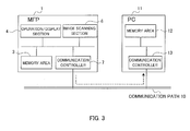
- Fig. 3 is a connection diagram of an image transfer system according to the invention. Fig. 3 shows only elements related to image transmission and reception.
- a PC (Personal Computer) 11 receives the image data from the MFP 1.
- the PC 11 includes a communication control unit 13 for executing a series of operations for establishing connection between the PC 11 and a communication path 10 such as network, USB and the like, and a memory area 12 for storing the image information.
- a communication path 10 such as network, USB and the like
- a memory area 12 for storing the image information.
- the PC 11 is a file server computer, such as NAS (Network Attached Storage) and the like, used with connection to a network.
- Initial configuration of the PC 11 is done with input devices such as keyboard and mouse and with a display for displaying configuration screen. But if the PC 11 works as a normal file server computer, those external input devices are not connected.
- the PC 11 is controlled by another PC using a Web browser or the like. In that case, only a person such as an administrator, who has authority to change configurations, changes the configurations.
- the PC 11 shall not be operated unless authentication information such as a user name and a password is supplied.
- FIG. 4A is a sequence diagram describing a transfer procedure between the MFP 1 and the PC 11.
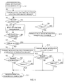
- FIG. 5 is a flow chart describing a series of operations of the MFP 1.
- Fig. 4A is a diagram describing a transfer procedure where the image data is normally stored in the file server.
- Fig. 4B is a diagram describing a transfer procedure where transfer of the image data is terminated due to an error occurred during the transfer.
- the user sets the document or the image to be scanned on the image scanning section 6 of the MFP 1 and configures a destination of transmission of the image data with the operation/display section 4, and then, the MFP 1 goes into an image information transmission starting state at step S1 in Fig. 5 .
- the communication controller 7 transmits an image information storage location confirmation request command to an apparatus specified as the destination of transmission (i.e., the PC 11 in case of the first embodiment) through the communication path 10 at step S2 in Fig. 5 and step 20 in Figs. 4A, 4B .
- the communication controller 7 of the MFP 1 and the communication controller 13 of the PC 11 communicates with each other via FTP (File Transfer Protocol). Specifically, the MFP 1 transmits open command to the PC 11 to try to communicate with the PC 11 at step S1.
- FTP File Transfer Protocol
- the MFP 1 waits for a reply from the PC 11 at step S3 in Fig. 5 .
- the communication controller 7 of the MFP 1 does not receive any response from the communication controller 13 of the PC 11 for a certain period of time after trying to connect to the PC 11 ("NO" at step S3 in Fig. 5 )
- the communication controller 7 determines timeout ("YES" at step S4 in Fig. 5 ), and assumes that the image information transfer is terminated due to error, thus terminating a connection procedure with the PC 11 (step S 15 in Fig. 5 ).
- the communication controller 7 of the MFP 1 displays to this effect on the operation/display section 4.
- the configuration of a timeout period for waiting for the response from the PC 11 can be changed with the operation/display section 4.
- the communication controller 7 of the MFP 1 receives within the timeout period a confirmation from the communication controller 13 of the PC 11 ("OK" at step S3 in Fig 5 and the confirmation 21 in Figs. 4A and 4B )
- the communication controller 7 of the MFP 1 continues to transmit the image data to the PC 11 with put or mput command (step S.5 in Fig. 5 and the image data transmission 22 in Figs. 4A and 4B ) until the transmission of the image data terminates (step S6 in Fig. 5 ).
- the communication controller 7 of the MFP 1 makes a judgment as to whether the termination of the transmission results from completion of the image data transmission or from an error such as a network traffic error or an error due to storage capacity shortage of the PC11 (step S7 in Fig. 5 ).
- the communication controller 7 of the MFP 1 transmits a get command to the communication controller 13 of the PC 11 to retrieve a registration information file of the image data stored in the PC 11 or transmits a dir command to obtain a registration list of the image data.
- the communication controller 7 of the MFP 1 determines whether the transmission of the image data has been successfully completed by comparing the registration and transmission information of the image data in the MFP 1 and a registration situation of the image data retrieved from the PC 11. That is, the communication controller 7 of the MFP 1 determines whether the transmission of the image data has been successfully completed by comparing a file containing the image data stored in the MFP 1 and a file containing the image data transmitted and now stored in the PC 11 with respect to file information thereof such as a filename, a file size, a hash value, a timestamp, and the like.
- the communication controller 7 of the MFP 1 determines that the transmission is terminated due to occurrence of an error ("YES" at step S7 in Fig. 5 )
- the communication controller 7 transmits an image information deletion request, that is, a delete command, to the communication controller 13 of the PC 11 (step S12 in Fig. 5 and the deletion request 26 in Fig. 4B ).
- the PC 11 executes the image information deletion, and the communication controller 7 of the MFP 1 waits for a response from the PC 11 (step S 13 in Fig. 5 ). Even where the communication controller 7 of the MFP 1 does not receive the response from the communication controller 13 of the PC 11 ("NO" at step S13 in Fig. 5 ) and the timeout period passes ("YES" at step S 14 in Fig. 5 ), the communication controller 7 of the MFP 1 assumes that the image information transmission has been completed (step S11 in Fig. 5 ) and displays to that effect on the operation/display section 4.
- the timeout period for waiting for the response from the PC 11 can be configured with the operation/display section 4.
- the communication controller 7 of the MFP 1 receives the response from the communication controller 13 of the PC 11 ("YES" at step S 13 in Fig. 5 and the deletion confirmation 27 in Fig. 4B ), the communication controller 7 of the MFP 1 also assumes that the image information transmission has been completed (step S11 in Fig. 5 ).
- the communication controller 7 of the MFP 1 determines that the termination of the transmission does not result from an error ("NO" at step S7 in Fig. 5 )
- the communication controller 7 of the MFP 1 transmits an image information transmission completion confirmation request (step S8 in Fig. 5 and the request 24 in Fig. 4A ).
- the communication controller 7 of the MFP 1 waits for a response to the image information transmission completion confirmation request from the PC 11 for a certain period of time (step S9 in Fig. 5 ).
- the communication controller 7 of the MFP 1 does not receive the response from the communication controller 13 of the PC 11 ("NO” at step S9 in Fig. 5 ) and the timeout period passes, the communication controller 7 of the MFP 1 assumes that the image information transmission has been completed ("YES" at step S 10 in Fig. 5 ), and displays that no response is received from the PC 11 on the operation/display section 4.
- the timeout period for waiting for the response from the PC 11 can be configured with the operation/display section 4.
- the communication controller 7 of the MFP 1 receives within the timeout period a confirmation responding to the image information transmission completion confirmation request ("OK" at step S9 in Fig. 5 and the confirmation 25 in Fig. 4A ), the communication controller 7 of the MFP 1 assumes that the image information transmission has been completed (step S11 in Fig. 5 ), and determines that the memory area 12 of the PC 11 does not store the incomplete image data transferred this time, then displaying to that effect on the operation/display section 4 and terminating the image information transfer process.
- the first embodiment prevents the incomplete image data from being accumulated in the file server even where a network traffic error or a storage capacity shortage error in the file server occurs while transmitting the image data from the image transferring apparatus to the file server.
- the structure of the second embodiment is the same as the first embodiment and is thus omitted. Operation of the second embodiment is hereinafter described with reference to Figs. 6 and 7 .
- Fig. 6 is a sequence diagram describing a transfer procedure between a MFP 21 and the PC 11.
- Fig. 7 is a flow chart describing a series of operation of the MFP 21.
- the second embodiment is different from the first embodiment with respect to operations after the image data has been completely transmitted from the MFP 21 to the PC 11, and accordingly, the description about portions that are the same as the first embodiment is omitted, and only operation steps after the transfer of the image data is hereinafter described.
- the communication controller 7 of the MFP 21 determines that the termination of the transmission does not result from an error ("NO" at step S7 in Fig. 7 )
- the communication controller 7 of the MFP 21 transmits the image data information transmission completion confirmation request (step S8 in Fig. 7 and the transmission completion 24 in Fig. 6 ).
- the communication controller 7 of the MFP 21 waits for the response to the image data information transmission completion confirmation request from the PC 11 for the prescribed period of time (step S9 in Fig. 7 ).
- the communication controller 7 of the MFP 1 does not receive the response from the communication controller of the PC 11 ("NO” at step S9 in Fig. 7 ) and the timeout period passes ("YES” at step S10 in Fig. 7 ), the communication controller 7 of the MFP 1 assumes that the transmission completion confirmation has been received as a response to the image data information transmission completion confirmation request ("YES" at step S10 in Fig. 10), but displays that no response is received from the PC 11 on the operation/display section 4.
- the timeout period for waiting for the response from the PC 11 can be configured with the operation/display section 4.
- the communication controller 7 of the MFP 1 receives within the timeout period a confirmation responding to the image information transmission completion confirmation request ("OK" at step S9 in Fig. 7 and the confirmation 25 in Fig. 6 ), the communication controller 7 of the MFP 1, the communication controller 7 of the MFP 1 goes into a standby mode for a period of time previously configured by the user with the operation/display section 4 (step S16 in Fig. 7 ).
- the above predetermined period can be arbitrarily configured by the user.
- the MFP 21 can transmit the image information deletion request to the PC 11 in a few days after the time and date of the transmission of the image data.
- the communication controller 7 of the MFP 21 transmits the image information deletion request, that is, the delete command to the communication controller 13 of the PC 11 (step S12 in Fig. 7 and deletion request 26 in Fig. 6 ).
- the PC 11 executes the image information deletion, and the communication controller 7 of the MFP 21 waits for the response to the image information deletion request (step S 13 in Fig. 7 ). Even where the communication controller 7 of the MFP 21 does not receive the response from the communication controller 13 of the PC 11 ("NO" at step S 13 in Fig. 7 ) and the timeout period passes ("YES" at step S14 in Fig. 7 ), the communication controller 7 of the MFP 21 assumes that the image information transmission has been completed (step S11 in Fig. 7 ) and displays to that effect on the operation/display section 4.
- the timeout period for waiting for the response from the PC 11 can be configured with the operation/display section 4.
- the communication controller 7 of the MFP 21 determines that the memory area 12 of the PC 11 does not store the image data transferred this time and displays to that effect on the operation/display section 4.
- the apparatus of the second embodiment prevents the unnecessary image data from being left in the file server even where a network traffic error or a storage capacity shortage error in the file server occurs during the image data transmission from the image transferring apparatus to the file server. Furthermore, the apparatus of the second embodiment deletes the image data stored in the file server when a certain period of time passes after completion of the image data transmission, thus improving security of the image data.
- FTP is employed as a communication protocol between the image transferring apparatus and the file server, but various communication protocols other than the FTP, such as TFTP (Trivial File Transfer Protocol), HTTP (Hypertext Transfer Protocol), NFS (Network File System), WebDAV (Distributed Authoring and Versioning protocol for the WWW), and SMB (Server Message Block) may be employed.
- TFTP Trivial File Transfer Protocol
- HTTP Hypertext Transfer Protocol
- NFS Network File System
- WebDAV Distributed Authoring and Versioning protocol for the WWW
- SMB Server Message Block
- the MFP is exemplified as the image transferring apparatus, but this invention can be applied to an apparatus having a function for inputting and transmitting image information, such as a facsimile, a scanner, and a photocopier.
Landscapes
- Engineering & Computer Science (AREA)
- Multimedia (AREA)
- Signal Processing (AREA)
- General Engineering & Computer Science (AREA)
- Computing Systems (AREA)
- Facsimiles In General (AREA)
- Facsimile Transmission Control (AREA)
- Storing Facsimile Image Data (AREA)
Abstract
Description
- The present invention relates to an image transferring apparatus for transmitting image data.
- Image transferring apparatuses have been known as represented as, e.g., MFPs (Multifunction Peripheral) that has a function to transfer image data of read documents to a file server on a network.
- For example, Japanese Patent Application Publication No.
2000-287052 - Many arts have been disclosed that ensure certainty and reliability in transmission and reception of the image data between the image transferring apparatus and receiving apparatuses such as file servers, but few inventions regard handling of incomplete image data caused by errors such as anomaly network traffics in addition to image data transmission and reception technology as described above.
- Incomplete image data tend to be handled roughly in comparison with complete image data, and in some case, are neglected inadvertently as they are. Where the image data and the like include various types of information requiring due care of a high degree such as corporation's secrets and personal information, the image data must be handled particularly gingerly even though the image data is incomplete.
- Where errors occur such as anomaly network traffics during reading of the original documents or during transmission of the image data on the side of image transferring apparatus, the incomplete image file received on the side of the file sever usually remains in a memory portion on the side of the file server unless intentionally deleted on the side of the file server, and may bring about risks of allowing information to be divulged to a malicious third party.
- The present invention was invented in consideration of the above problems. An object of the present invention is to provide an image transferring apparatus which ensures reliable image data transmission and also ensures security of incomplete image data received by the file server even where a network traffic error and the like occurs.
- According to one aspect of the invention, to solve the above problems, an image transferring apparatus for transmitting image data to a file server has an image input unit allowing input of image as the image data, a memory section for storing the image data, and registration and transmission information of the image data, and a communication controller for transmitting the image data stored in the memory section to the file server. The communication controller has a judgment unit for making a judgment based on the registration and transmission information of the image data as to whether communication condition of the image data is normal or not. The communication controller transmits a request for deleting the image data to the file server in the case where the judgment is made that the communication condition is not normal during transmission of the image data stored in the memory section to the file server.
- The image transferring apparatus according to one aspect of the invention has an information input section for scanning an image as image data. The image transferring apparatus according to one aspect of the invention has a memory section for storing image data, and a registration information of a file name and transmission date and time information of the image data. The image transferring apparatus further has a communication controller for transmitting the image data to the file server.
- The communication controller of the image transferring apparatus according to one aspect of the invention has a judgment section for making a judgment as to whether the image data is appropriately transmitted to the file server, based on a file name of the image data transmitted to the file server and date and time when the image data was transmitted.
- Where the judgment section makes a judgment that an error such as a network traffic error or the like occurs during communication between the image transferring apparatus and the file server, the communication controller transmits a command for requesting deletion of the image data to the file server, so that the image data, which is stored in an incomplete condition in the file server, is to be deleted.
- The image transferring apparatus according to one aspect of the invention ensures the image data transmission to the file server, thereby securing security of the incomplete image data received at the file server side in the event of an error such as a network traffic error.
- This invention may take physical form in certain parts and arrangements of parts, a preferred embodiment and method of which will be described in detail in this specification and illustrated in the accompanying drawings which form a part hereof, and wherein:
-
Fig. 1 is a cross-sectional view showing an example of configuration of an image transferring apparatus according to the invention; -
Fig. 2 is a block diagram of anMFP 1 according to the invention; -
Fig. 3 is a connection diagram of an image transfer system according to the invention; -
Fig. 4A is a sequence diagram illustrating a transfer procedure conducted between theMFP 1 and aPC 11 according to the first embodiment of the invention; -
Fig. 4B is a sequence diagram illustrating a transfer procedure conducted between theMFP 1 and thePC 11 according to the first embodiment of the invention; -
Fig. 5 is a flow chart illustrating a sequence of a general operation of the MFP according to the first embodiment of the invention; -
Fig. 6 is a sequence diagram illustrating a transfer procedure conducted between theMFP 1 and thePC 11 according to the second embodiment of the invention; and -
Fig. 7 is a flow chart illustrating a sequence of a general operation of the MFP according to the second embodiment of the invention. - An image transferring apparatus according to the first embodiment of the invention is described hereinafter with reference to
Figs. 1 to 3 .Fig. 1 is a cross-sectional view showing an example of configuration of the image transferring apparatus according to the invention, and in this embodiment, an MFP is described. AnMFP 1 has animage scanning section 6 as an image input unit, animage printing section 8, and amedium feeding section 9. - The
image scanning section 6 includes a flat bed scanner having an image scanning sensor and scans an image to read the image. - The
image printing section 8 includes an image forming unit composed of an image drum for forming images on paper and a transfer roller, and also includes a fuser unit for fusing on the paper the image formed with the image forming unit. - The
medium feeding section 9 includes a feeding tray having a curved portion in the center of a medium stacking surface thereof, a pair of guiding units for positioning both widthwise ends of a medium, a feeding roller for separating media sheet by sheet and feeding the separated medium, and a discharging roller for discharging the medium whose image has been scanned to the discharge tray. -
Fig. 2 is a block diagram of theMFP 1 according to the invention. TheMFP 1 is composed of a CPU (Central Processing Unit) 2 for performing overall control of the apparatus, amemory area 3 composed of a RAM (Random Access Memory), a flash memory, and the like, an operation/display section 4 such as an operation panel or an LCD (Liquid Crystal Display), aprogram storage area 5 composed of a ROM (Read Only Memory), a flash memory, and the like, theimage scanning section 6, acommunication controller 7, and animage printing section 8. - The
CPU 2 is composed of a microprocessor or the like and performs overall control of theMFP 1 by executing a program (firmware) stored in theprogram storage area 5. - The
memory area 3 is composed of a RAM, a flash memory, and the like, as described above, and stores various types of configuration information while temporarily storing information necessary for program execution. - The operation/
display section 4 receives manipulation of information input operation and displays an apparatus status during operations, various configuration information, and the like. - The
program storage area 5 is composed of a nonvolatile memory such as the ROM and the flash memory as described above, and stores a program necessary for overall control of theMFP 1. - The
communication controller 7 performs a series of operations to establish connection with, for example, network, USB (Universal Serial Bus), and the like. - The
image printing section 8 prints image data onto a recording medium or the like. Themedium feeding section 9 automatically feeds a document, which a user intends to scan, to theimage scanning section 6. -
Fig. 3 is a connection diagram of an image transfer system according to the invention.Fig. 3 shows only elements related to image transmission and reception. - In this embodiment, a PC (Personal Computer) 11 receives the image data from the
MFP 1. The PC 11 includes acommunication control unit 13 for executing a series of operations for establishing connection between the PC 11 and acommunication path 10 such as network, USB and the like, and amemory area 12 for storing the image information. It is herein assumed that the PC 11 is a file server computer, such as NAS (Network Attached Storage) and the like, used with connection to a network. - Initial configuration of the PC 11 is done with input devices such as keyboard and mouse and with a display for displaying configuration screen. But if the PC 11 works as a normal file server computer, those external input devices are not connected.
- It is also possible that the PC 11 is controlled by another PC using a Web browser or the like. In that case, only a person such as an administrator, who has authority to change configurations, changes the configurations. The PC 11 shall not be operated unless authentication information such as a user name and a password is supplied.
- Operation of the apparatus according to the first embodiment will be hereinafter described with reference to
Figs. 4A, 4B , and5 . Each ofFigs. 4A and 4B is a sequence diagram describing a transfer procedure between theMFP 1 and thePC 11.Fig. 5 is a flow chart describing a series of operations of theMFP 1.Fig. 4A is a diagram describing a transfer procedure where the image data is normally stored in the file server.Fig. 4B is a diagram describing a transfer procedure where transfer of the image data is terminated due to an error occurred during the transfer. - The transfer procedures of
Figs. 4A, 4B are the same until completion of transfer of the image data, and accordingly, it is assumed in the below explanation that a confirmingcommand 20 and aconfirmation 21 inFigs. 4A, 4B and procedures up to step S7 inFig. 5 are common. - First, the user sets the document or the image to be scanned on the
image scanning section 6 of theMFP 1 and configures a destination of transmission of the image data with the operation/display section 4, and then, theMFP 1 goes into an image information transmission starting state at step S1 inFig. 5 . - When the user enters an image transfer starting instruction with the operation/
display section 4, thecommunication controller 7 transmits an image information storage location confirmation request command to an apparatus specified as the destination of transmission (i.e., thePC 11 in case of the first embodiment) through thecommunication path 10 at step S2 inFig. 5 and step 20 inFigs. 4A, 4B . - The
communication controller 7 of theMFP 1 and thecommunication controller 13 of thePC 11 communicates with each other via FTP (File Transfer Protocol). Specifically, theMFP 1 transmits open command to thePC 11 to try to communicate with thePC 11 at step S1. - Thereafter, the
MFP 1 waits for a reply from thePC 11 at step S3 inFig. 5 . Where thecommunication controller 7 of theMFP 1 does not receive any response from thecommunication controller 13 of thePC 11 for a certain period of time after trying to connect to the PC 11 ("NO" at step S3 inFig. 5 ), thecommunication controller 7 determines timeout ("YES" at step S4 inFig. 5 ), and assumes that the image information transfer is terminated due to error, thus terminating a connection procedure with the PC 11 (step S 15 inFig. 5 ). - Where the image information transfer is terminated due to error, the
communication controller 7 of theMFP 1 displays to this effect on the operation/display section 4. The configuration of a timeout period for waiting for the response from thePC 11 can be changed with the operation/display section 4. - Where the
communication controller 7 of theMFP 1 receives within the timeout period a confirmation from thecommunication controller 13 of the PC 11 ("OK" at step S3 inFig 5 and theconfirmation 21 inFigs. 4A and 4B ), thecommunication controller 7 of theMFP 1 continues to transmit the image data to thePC 11 with put or mput command (step S.5 inFig. 5 and theimage data transmission 22 inFigs. 4A and 4B ) until the transmission of the image data terminates (step S6 inFig. 5 ). - When the transmission of the image data terminates ("YES" at step S6 in
Fig. 5 ), thecommunication controller 7 of theMFP 1 then makes a judgment as to whether the termination of the transmission results from completion of the image data transmission or from an error such as a network traffic error or an error due to storage capacity shortage of the PC11 (step S7 inFig. 5 ). - The
communication controller 7 of theMFP 1 transmits a get command to thecommunication controller 13 of thePC 11 to retrieve a registration information file of the image data stored in thePC 11 or transmits a dir command to obtain a registration list of the image data. - Then, the
communication controller 7 of theMFP 1 determines whether the transmission of the image data has been successfully completed by comparing the registration and transmission information of the image data in theMFP 1 and a registration situation of the image data retrieved from thePC 11. That is, thecommunication controller 7 of theMFP 1 determines whether the transmission of the image data has been successfully completed by comparing a file containing the image data stored in theMFP 1 and a file containing the image data transmitted and now stored in thePC 11 with respect to file information thereof such as a filename, a file size, a hash value, a timestamp, and the like. - Where the
communication controller 7 of theMFP 1 determines that the transmission is terminated due to occurrence of an error ("YES" at step S7 inFig. 5 ), thecommunication controller 7 transmits an image information deletion request, that is, a delete command, to thecommunication controller 13 of the PC 11 (step S12 inFig. 5 and thedeletion request 26 inFig. 4B ). - The
PC 11 executes the image information deletion, and thecommunication controller 7 of theMFP 1 waits for a response from the PC 11 (step S 13 inFig. 5 ). Even where thecommunication controller 7 of theMFP 1 does not receive the response from thecommunication controller 13 of the PC 11 ("NO" at step S13 inFig. 5 ) and the timeout period passes ("YES" at step S 14 inFig. 5 ), thecommunication controller 7 of theMFP 1 assumes that the image information transmission has been completed (step S11 inFig. 5 ) and displays to that effect on the operation/display section 4. The timeout period for waiting for the response from thePC 11 can be configured with the operation/display section 4. - Where the
communication controller 7 of theMFP 1 receives the response from thecommunication controller 13 of the PC 11 ("YES" at step S 13 inFig. 5 and thedeletion confirmation 27 inFig. 4B ), thecommunication controller 7 of theMFP 1 also assumes that the image information transmission has been completed (step S11 inFig. 5 ). - On the other hand, where the
communication controller 7 of theMFP 1 determines that the termination of the transmission does not result from an error ("NO" at step S7 inFig. 5 ), thecommunication controller 7 of theMFP 1 transmits an image information transmission completion confirmation request (step S8 inFig. 5 and therequest 24 inFig. 4A ). - The
communication controller 7 of theMFP 1 waits for a response to the image information transmission completion confirmation request from thePC 11 for a certain period of time (step S9 inFig. 5 ). - Where the
communication controller 7 of theMFP 1 does not receive the response from thecommunication controller 13 of the PC 11 ("NO" at step S9 inFig. 5 ) and the timeout period passes, thecommunication controller 7 of theMFP 1 assumes that the image information transmission has been completed ("YES" at step S 10 inFig. 5 ), and displays that no response is received from thePC 11 on the operation/display section 4. The timeout period for waiting for the response from thePC 11 can be configured with the operation/display section 4. - Where the
communication controller 7 of theMFP 1 receives within the timeout period a confirmation responding to the image information transmission completion confirmation request ("OK" at step S9 inFig. 5 and theconfirmation 25 inFig. 4A ), thecommunication controller 7 of theMFP 1 assumes that the image information transmission has been completed (step S11 inFig. 5 ), and determines that thememory area 12 of thePC 11 does not store the incomplete image data transferred this time, then displaying to that effect on the operation/display section 4 and terminating the image information transfer process. - As described above, the first embodiment prevents the incomplete image data from being accumulated in the file server even where a network traffic error or a storage capacity shortage error in the file server occurs while transmitting the image data from the image transferring apparatus to the file server.
- The structure of the second embodiment is the same as the first embodiment and is thus omitted. Operation of the second embodiment is hereinafter described with reference to
Figs. 6 and7 . -
Fig. 6 is a sequence diagram describing a transfer procedure between aMFP 21 and thePC 11.Fig. 7 is a flow chart describing a series of operation of theMFP 21. - The second embodiment is different from the first embodiment with respect to operations after the image data has been completely transmitted from the
MFP 21 to thePC 11, and accordingly, the description about portions that are the same as the first embodiment is omitted, and only operation steps after the transfer of the image data is hereinafter described. - Where the
communication controller 7 of theMFP 21 determines that the termination of the transmission does not result from an error ("NO" at step S7 inFig. 7 ), thecommunication controller 7 of theMFP 21 transmits the image data information transmission completion confirmation request (step S8 inFig. 7 and thetransmission completion 24 inFig. 6 ). - The
communication controller 7 of theMFP 21 waits for the response to the image data information transmission completion confirmation request from thePC 11 for the prescribed period of time (step S9 inFig. 7 ). - Where the
communication controller 7 of theMFP 1 does not receive the response from the communication controller of the PC 11 ("NO" at step S9 inFig. 7 ) and the timeout period passes ("YES" at step S10 inFig. 7 ), thecommunication controller 7 of theMFP 1 assumes that the transmission completion confirmation has been received as a response to the image data information transmission completion confirmation request ("YES" at step S10 in Fig. 10), but displays that no response is received from thePC 11 on the operation/display section 4. The timeout period for waiting for the response from thePC 11 can be configured with the operation/display section 4. - Where the
communication controller 7 of theMFP 1 receives within the timeout period a confirmation responding to the image information transmission completion confirmation request ("OK" at step S9 inFig. 7 and theconfirmation 25 inFig. 6 ), thecommunication controller 7 of theMFP 1, thecommunication controller 7 of theMFP 1 goes into a standby mode for a period of time previously configured by the user with the operation/display section 4 (step S16 inFig. 7 ). - The above predetermined period can be arbitrarily configured by the user. For example, the
MFP 21 can transmit the image information deletion request to thePC 11 in a few days after the time and date of the transmission of the image data. - When the predetermined period passes ("YES" at step S 16 in
Fig. 7 ), thecommunication controller 7 of theMFP 21 then transmits the image information deletion request, that is, the delete command to thecommunication controller 13 of the PC 11 (step S12 inFig. 7 anddeletion request 26 inFig. 6 ). - The
PC 11 executes the image information deletion, and thecommunication controller 7 of theMFP 21 waits for the response to the image information deletion request (step S 13 inFig. 7 ). Even where thecommunication controller 7 of theMFP 21 does not receive the response from thecommunication controller 13 of the PC 11 ("NO" at step S 13 inFig. 7 ) and the timeout period passes ("YES" at step S14 inFig. 7 ), thecommunication controller 7 of theMFP 21 assumes that the image information transmission has been completed (step S11 inFig. 7 ) and displays to that effect on the operation/display section 4. The timeout period for waiting for the response from thePC 11 can be configured with the operation/display section 4. - Where the
communication controller 7 of theMFP 1 receives within the timeout period the deletion confirmation responding to the image information deletion request from thecommunication controller 13 of the PC 11 ("OK" at step S 13 inFig 7 and thedeletion confirmation 27 inFigs. 6 ), thecommunication controller 7 of theMFP 21 determines that thememory area 12 of thePC 11 does not store the image data transferred this time and displays to that effect on the operation/display section 4. - As described above, the apparatus of the second embodiment prevents the unnecessary image data from being left in the file server even where a network traffic error or a storage capacity shortage error in the file server occurs during the image data transmission from the image transferring apparatus to the file server. Furthermore, the apparatus of the second embodiment deletes the image data stored in the file server when a certain period of time passes after completion of the image data transmission, thus improving security of the image data.
- In this embodiment, FTP is employed as a communication protocol between the image transferring apparatus and the file server, but various communication protocols other than the FTP, such as TFTP (Trivial File Transfer Protocol), HTTP (Hypertext Transfer Protocol), NFS (Network File System), WebDAV (Distributed Authoring and Versioning protocol for the WWW), and SMB (Server Message Block) may be employed.
- In the embodiments, the MFP is exemplified as the image transferring apparatus, but this invention can be applied to an apparatus having a function for inputting and transmitting image information, such as a facsimile, a scanner, and a photocopier.
- Each embodiment is a preferred embodiment of this invention but this invention is not limited thereto. Each structure of the invention can be arbitrarily modified without departing from the scope of the invention.
- The foregoing description of preferred embodiments of the invention has been presented for purposes of illustration and description, and is not intended to be exhaustive or to limit the invention to the precise form disclosed. The description was selected to best explain the principles of the invention and their practical application to enable others skilled in the art to best utilize the invention in various embodiments and various modifications as are suited to the particular use contemplated. It is intended that the scope of the invention should not be limited by the specification, but be defined by the claims set forth below.
Claims (10)
- An image transferring apparatus for transmitting image data to a file server, comprising:an image input unit allowing input of image as the image data;a memory section for storing the image data, registration information of the image data, and transmission information of the image data; anda communication controller for transmitting the image data stored in said memory section to said file server, wherein:said communication controller has a judgment unit for making a judgment based on the registration information and the transmission information as to whether communication condition of the image data is normal or not; andsaid communication controller transmits a request for deleting the image data to said file server where said judgment is made that said communication condition is not normal during transmission of the image data stored in said memory section to said file server.
- An image transferring apparatus for transmitting image data to a file server, comprising:an image input unit allowing input of image as the image data;a memory section for storing the image data, registration information of the image data, and transmission information of the image data; anda communication controller for transmitting the image data stored in said memory section to said file server, wherein:said communication controller has a judgment unit for making a judgment based on the registration information and the transmission information as to whether communication condition of the image data is normal or not; andsaid communication controller transmits a request for deleting the image data stored in said file server to said file server after a predetermined period passes from completion of transmission of the image data to said file server.
- An image transferring apparatus for transmitting image data to a file server, comprising:an image input unit allowing input of an image as the image data;a memory section in which the image data is saved as a first file;a communication controller transmitting the first file to said file server so that the first file is saved in the file server as the second file,wherein said communication controller transmits to said file server a request to delete the second file where transmission of the first file to said file server has not been successfully completed.
- The image transferring apparatus according to claim 3, wherein said communication controller determines whether the transmission of the first file to said file server has been successfully completed by comparing the first file and the second file with respect to a file information thereof.
- The image transferring apparatus according to claim 4, wherein the file information is a file name of the first file or the second file.
- The image transferring apparatus according to claim 4, wherein the file information is a file size of the first file or the second file.
- The image transferring apparatus according to claim 4, wherein the file information is a hash value of the first file or the second file.
- The image transferring apparatus according to claim 4, wherein the file information is a time stamp of the first file or the second file.
- The image transferring apparatus according to claim 3, wherein said communication controller transmits to said file server the request to delete the second file where a prescribed period of time passes since the transmission of the first file to said file server.
- The apparatus of claim 3, further comprising one or more of the additional features of one of claims 1 or 2.
Applications Claiming Priority (1)
| Application Number | Priority Date | Filing Date | Title |
|---|---|---|---|
| JP2007041054A JP4392437B2 (en) | 2007-02-21 | 2007-02-21 | Image transfer device |
Publications (2)
| Publication Number | Publication Date |
|---|---|
| EP1962486A2 true EP1962486A2 (en) | 2008-08-27 |
| EP1962486A3 EP1962486A3 (en) | 2009-03-18 |
Family
ID=39493524
Family Applications (1)
| Application Number | Title | Priority Date | Filing Date |
|---|---|---|---|
| EP08101782A Ceased EP1962486A3 (en) | 2007-02-21 | 2008-02-20 | Image transferring apparatus |
Country Status (3)
| Country | Link |
|---|---|
| US (1) | US8098387B2 (en) |
| EP (1) | EP1962486A3 (en) |
| JP (1) | JP4392437B2 (en) |
Cited By (1)
| Publication number | Priority date | Publication date | Assignee | Title |
|---|---|---|---|---|
| EP2169934A1 (en) * | 2008-09-26 | 2010-03-31 | Brother Kogyo Kabushiki Kaisha | Image scanner and image scanning system |
Families Citing this family (6)
| Publication number | Priority date | Publication date | Assignee | Title |
|---|---|---|---|---|
| US8064077B2 (en) * | 2008-10-31 | 2011-11-22 | Infoprint Solutions Company Llc | Automatic print job cancellation mechanism |
| WO2010113670A1 (en) * | 2009-03-30 | 2010-10-07 | 日本電気株式会社 | Communication system, communication terminal, server, data storing method and recording medium |
| US8380820B1 (en) * | 2011-04-08 | 2013-02-19 | Cellco Partnership | Sending synchronous responses to requests from frontend applications |
| JP2013045195A (en) * | 2011-08-23 | 2013-03-04 | Hitachi Medical Corp | Medical image transfer system, and medical image transfer method |
| JP5679078B1 (en) * | 2014-02-04 | 2015-03-04 | 富士ゼロックス株式会社 | Data storage system, image processing apparatus, and program |
| JP2024016648A (en) * | 2022-07-26 | 2024-02-07 | シャープ株式会社 | image forming device |
Citations (2)
| Publication number | Priority date | Publication date | Assignee | Title |
|---|---|---|---|---|
| US20030128402A1 (en) | 2001-12-28 | 2003-07-10 | Murata Kikai Kabushiki Kaisha | Internet facsimile machine |
| US20040075871A1 (en) | 2002-10-18 | 2004-04-22 | Nobuhiro Itoh | Facsimile communication method, facsimile apparatus and computer-readable storage medium |
Family Cites Families (11)
| Publication number | Priority date | Publication date | Assignee | Title |
|---|---|---|---|---|
| JPH08293989A (en) | 1995-04-21 | 1996-11-05 | Ricoh Co Ltd | Facsimile communication device |
| JP3062679B2 (en) * | 1995-05-31 | 2000-07-12 | シャープ株式会社 | Network printer system |
| JPH09284434A (en) * | 1996-04-16 | 1997-10-31 | Oki Data:Kk | Facsimile equipment |
| JPH1056547A (en) | 1996-08-09 | 1998-02-24 | Ricoh Co Ltd | Facsimile machine |
| JP3854699B2 (en) * | 1996-12-27 | 2006-12-06 | キヤノン株式会社 | Printing system and printing interruption method |
| JP2001111734A (en) | 1999-10-04 | 2001-04-20 | Canon Inc | Image communication method and image communication device |
| JP3670535B2 (en) | 1999-01-28 | 2005-07-13 | シャープ株式会社 | Image information transmission device |
| JP2001016252A (en) | 1999-07-01 | 2001-01-19 | Canon Inc | Communication device, communication method, communication system, and storage medium |
| JP4101023B2 (en) * | 2002-11-05 | 2008-06-11 | シャープ株式会社 | Network scanner |
| JP3734037B2 (en) | 2003-12-22 | 2006-01-11 | 村田機械株式会社 | Communication terminal device |
| JP4726435B2 (en) * | 2004-05-28 | 2011-07-20 | 株式会社沖データ | Image processing apparatus and image forming system |
-
2007
- 2007-02-21 JP JP2007041054A patent/JP4392437B2/en not_active Expired - Fee Related
-
2008
- 2008-02-20 EP EP08101782A patent/EP1962486A3/en not_active Ceased
- 2008-02-21 US US12/034,911 patent/US8098387B2/en not_active Expired - Fee Related
Patent Citations (2)
| Publication number | Priority date | Publication date | Assignee | Title |
|---|---|---|---|---|
| US20030128402A1 (en) | 2001-12-28 | 2003-07-10 | Murata Kikai Kabushiki Kaisha | Internet facsimile machine |
| US20040075871A1 (en) | 2002-10-18 | 2004-04-22 | Nobuhiro Itoh | Facsimile communication method, facsimile apparatus and computer-readable storage medium |
Cited By (5)
| Publication number | Priority date | Publication date | Assignee | Title |
|---|---|---|---|---|
| EP2169934A1 (en) * | 2008-09-26 | 2010-03-31 | Brother Kogyo Kabushiki Kaisha | Image scanner and image scanning system |
| US20100079797A1 (en) * | 2008-09-26 | 2010-04-01 | Brother Kogyo Kabushiki Kaisha | Image Scanner and Image Scanning System |
| US8553256B2 (en) | 2008-09-26 | 2013-10-08 | Brother Kogyo Kabushiki Kaisha | Image scanner and image scanning system |
| US8681366B2 (en) | 2008-09-26 | 2014-03-25 | Brother Kogyo Kabushiki Kaisha | Image scanner and image scanning system |
| US9300843B2 (en) | 2008-09-26 | 2016-03-29 | Brother Kogyo Kabushiki Kaisha | Image scanner and image scanning system |
Also Published As
| Publication number | Publication date |
|---|---|
| EP1962486A3 (en) | 2009-03-18 |
| JP2008205936A (en) | 2008-09-04 |
| US8098387B2 (en) | 2012-01-17 |
| US20080212124A1 (en) | 2008-09-04 |
| JP4392437B2 (en) | 2010-01-06 |
Similar Documents
| Publication | Publication Date | Title |
|---|---|---|
| US8098387B2 (en) | Image transferring apparatus | |
| US11252284B2 (en) | Image processing apparatus associating with external apparatus, control method, and storage medium | |
| US8098386B2 (en) | Image management system, image output apparatus, and computer readable medium for security enhancement | |
| CN102238169B (en) | Communication device and control method thereof | |
| JP4582203B2 (en) | Image forming apparatus, communication control method and communication control program in the same | |
| JP4822544B2 (en) | Image forming apparatus capable of managing a plurality of module configuration information | |
| US8209377B2 (en) | Data processing apparatus and method | |
| CN112689063A (en) | Image forming apparatus and reception notification method | |
| US20180121653A1 (en) | Information processing system, information processing apparatus, and recording medium | |
| EP1477446A2 (en) | Information output method and apparatus | |
| US20080168554A1 (en) | Image forming apparatus and method of outputting | |
| US20160373460A1 (en) | Image forming apparatus, communication system, and program | |
| JP2009253588A (en) | Image processor | |
| JP2006041764A (en) | Log recording apparatus, log recording program, and recording medium | |
| JP2013025387A (en) | Information processor, control program, and information processing system | |
| US8873078B2 (en) | Image forming apparatus, print method, and recording medium involving a comparison between the number of sheets of e-paper and number of copies specified by user | |
| US20060227376A1 (en) | Secure image data system and method | |
| US8086764B2 (en) | Remote USB device usage system | |
| JP4638928B2 (en) | Authentication system, terminal device, and information processing device | |
| CN100542202C (en) | Image reading device and control method thereof | |
| JP6225561B2 (en) | Communication apparatus and program | |
| JP5070012B2 (en) | Image reading apparatus, image reading apparatus control method, and image reading apparatus control program | |
| JP2000326592A (en) | Image input / output device | |
| US20130010328A1 (en) | Information processing apparatus, fax reception notification control method, and storage medium | |
| US20180183960A1 (en) | Image reading device and image data transmitting method |
Legal Events
| Date | Code | Title | Description |
|---|---|---|---|
| PUAI | Public reference made under article 153(3) epc to a published international application that has entered the european phase |
Free format text: ORIGINAL CODE: 0009012 |
|
| AK | Designated contracting states |
Kind code of ref document: A2 Designated state(s): AT BE BG CH CY CZ DE DK EE ES FI FR GB GR HR HU IE IS IT LI LT LU LV MC MT NL NO PL PT RO SE SI SK TR |
|
| AX | Request for extension of the european patent |
Extension state: AL BA MK RS |
|
| PUAL | Search report despatched |
Free format text: ORIGINAL CODE: 0009013 |
|
| AK | Designated contracting states |
Kind code of ref document: A3 Designated state(s): AT BE BG CH CY CZ DE DK EE ES FI FR GB GR HR HU IE IS IT LI LT LU LV MC MT NL NO PL PT RO SE SI SK TR |
|
| AX | Request for extension of the european patent |
Extension state: AL BA MK RS |
|
| RIC1 | Information provided on ipc code assigned before grant |
Ipc: H04N 1/32 20060101AFI20090212BHEP |
|
| 17Q | First examination report despatched |
Effective date: 20090918 |
|
| 17P | Request for examination filed |
Effective date: 20090821 |
|
| AKX | Designation fees paid |
Designated state(s): DE FR GB NL |
|
| STAA | Information on the status of an ep patent application or granted ep patent |
Free format text: STATUS: THE APPLICATION HAS BEEN REFUSED |
|
| 18R | Application refused |
Effective date: 20151001 |