EP1962317B1 - Electromagnetic switching device - Google Patents
Electromagnetic switching device Download PDFInfo
- Publication number
- EP1962317B1 EP1962317B1 EP07003814A EP07003814A EP1962317B1 EP 1962317 B1 EP1962317 B1 EP 1962317B1 EP 07003814 A EP07003814 A EP 07003814A EP 07003814 A EP07003814 A EP 07003814A EP 1962317 B1 EP1962317 B1 EP 1962317B1
- Authority
- EP
- European Patent Office
- Prior art keywords
- armature
- magnet
- switching device
- force
- permanent magnet
- Prior art date
- Legal status (The legal status is an assumption and is not a legal conclusion. Google has not performed a legal analysis and makes no representation as to the accuracy of the status listed.)
- Not-in-force
Links
- 238000010586 diagram Methods 0.000 description 5
- 230000007423 decrease Effects 0.000 description 4
- 238000000418 atomic force spectrum Methods 0.000 description 3
- 230000003247 decreasing effect Effects 0.000 description 2
- 238000000034 method Methods 0.000 description 2
- 241001295925 Gegenes Species 0.000 description 1
- 230000001133 acceleration Effects 0.000 description 1
- 230000006835 compression Effects 0.000 description 1
- 238000007906 compression Methods 0.000 description 1
- 230000008602 contraction Effects 0.000 description 1
- 230000001419 dependent effect Effects 0.000 description 1
- 230000000694 effects Effects 0.000 description 1
- 230000005284 excitation Effects 0.000 description 1
- 230000004907 flux Effects 0.000 description 1
- 230000002401 inhibitory effect Effects 0.000 description 1
- 239000000696 magnetic material Substances 0.000 description 1
Images

Classifications
-
- H—ELECTRICITY
- H01—ELECTRIC ELEMENTS
- H01H—ELECTRIC SWITCHES; RELAYS; SELECTORS; EMERGENCY PROTECTIVE DEVICES
- H01H51/00—Electromagnetic relays
- H01H51/02—Non-polarised relays
- H01H51/04—Non-polarised relays with single armature; with single set of ganged armatures
- H01H51/06—Armature is movable between two limit positions of rest and is moved in one direction due to energisation of an electromagnet and after the electromagnet is de-energised is returned by energy stored during the movement in the first direction, e.g. by using a spring, by using a permanent magnet, by gravity
Definitions
- the invention relates to an electromagnetic switching device with an electromagnet and a movable armature, which is mounted in the switching device with a force acting against the closing force and different in an open position of zero holding force.
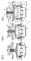
- FIG. 1 contains such a switching device, an electromagnet 1 with a magnetic yoke 2, on the example, two magnetic coils 4 are arranged for magnetic excitation.
- An armature 6 associated with the magnetic yoke 2 is resiliently mounted in a housing 10 of the switching device which is illustrated only symbolically by a return arrangement constructed from two return springs 8 connected in parallel.
- Magnetic yoke 2, solenoid 4 and armature 6 form an electromagnetic drive of the switching device.
- the armature 6 is non-positively connected via a prestressed contact spring 12 with a movable contact bridge 14.
- the movable contact bridge 14 are associated with two fixed contact carrier 16.
- the magnet armature 6 forms the actuator of the magnetic drive for the relative movement between the contact bridge 14 and the contact carrier sixteenth
- the contact bridge 14 and the fixed contact carrier 16 are each provided with contact pieces or contacts 18.
- the switching contact formed by the movable contact bridge 14 and the fixed contact carrier 16 is in the open position (OPEN position).
- the return springs 8 are biased so that the armature 6 is pressed in the rest position of the OPEN position with a biasing or holding force F 0 against a stop 22.
- FIG. 2 now shows a situation in which the contacts 18 touch the first time, the armature 6 has thus covered a distance s 0 .
- the further closing movement of the armature 6 is now carried out against the force exerted by the return springs 8 increasing spring forces and in addition against the action of the force exerted by the parallel contact spring 12, also increasing spring force. Since the spring force exerted by the preloaded contact spring 12 is significantly greater than the spring force exerted by the return spring 8, the total restoring force acting on the armature 6 increases abruptly.
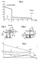
- the associated force curve is in FIG. 4 applied.
- the force exerted on the armature 6 by the return springs 8 and the contact spring 12 restoring force F against the distance d between the pole faces 60, 20 of the armature 6 and the magnetic yoke 2 is applied.
- the curve shows that the return springs 8 (FIG. FIG. 1 ) in the OPEN position the Holding force F 0 exercise. If current flows through the magnetic coils 4, the armature 6 moves under the action of the force exerted by the electromagnet 1 attraction and against the action of the return springs 8 toward the pole faces 20 of the magnetic yoke 2.
- the holding force F 0 exerted on the magnet armature 6 in the OPEN position secures the switching device in this position against accidental closing in the case of external mechanical vibration or impact load. Accordingly, during the entire distance traveled between d 0 and d S , the magnet armature 6 must always overcome the restoring force F exerted by the return springs 8, starting from a finite value required for mechanical securing of the magnet armature 6 in the OPEN position (holding force F 0 ) increases successively. In order nevertheless to achieve short switching times (high closing forces), it is therefore necessary to design and dimension the magnet system 2, 4, 6 such that the magnetic force acting on the magnet armature 6 is significantly higher than the restoring force exerted by the return springs 8. A disadvantage is the constant increase in the restoring forces over the entire working range (magnetic lifting). This results in relatively large, unneeded forces that must be overcome by a correspondingly powerful designed magnetic drive.
- the invention is therefore based on the object to provide an electromagnetic switching device with a magnetic armature, wherein the armature in an OPEN position with the electromagnet switched off by high holding forces on the one hand is securely fixed and on the other hand, the necessary for accelerating the magnet armature magnetic force is significantly reduced.
- the electromagnetic switching device includes an electromagnet and a movable armature which acts in the switching device with a force acting against the closing force and in an OPEN position of zero a different holding force is mounted, which is formed at least in part by a stationary in the switching device outside of the magnetic and magnet armature formed magnetic circuit arranged magnetic arrangement with a permanent magnet which exerts on the armature a dependent of the location of the armature restoring force, which in the OPEN- Position is maximum.
- the return spring can be designed with a smaller spring constant such that it has only a small holding force in the OPEN position.
- OPEN position generally refers to an operating situation of the switching device in which the electromagnet is de-energized and does not exert any magnetic force on the magnet armature.
- the invention is based on the consideration that the restoring force exerted on a movable magnet armature by a stationary permanent magnet in the switching device decreases with increasing distance between magnet armature and permanent magnet, so that on the one hand high holding forces are achieved in the OPEN position, and on the other hand with increasing distance of the magnet armature from the permanent magnet remove the restoring forces inhibiting its movement, so that high accelerations of the armature can be achieved even with smaller forces exerted by the magnetic drive forces.
- An electromagnetic switching device in which the holding force exerted on the magnet armature in the OPEN position is supported by a permanent magnet is basically already known from DE 196 08 729 C1 known.
- There two plate-shaped permanent magnets between an inner and outer yoke of an electromagnet are arranged. In the OPEN position, the magnet armature abuts with its armature plate on the outer yoke.
- Anchor plate, outer yoke, permanent magnet inner yoke and plunger core of the armature form in this way a closed magnetic circuit. Since the permanent magnet is disposed between the outer and inner yoke of the electromagnet, the known switching device can only be operated with direct current or with pulsed direct current. In addition, under certain circumstances, a current control is necessary, which limits the electrical holding power.
- the magnetic circuit must have a two-part yoke.
- the magnet assembly is disposed outside the magnetic circuit formed of electromagnet and armature, that does not affect this, the electromagnet can be energized both with direct current and with alternating current. By increasing the inductance in the closed state also results in a reduced alternating current automatically.
- An electromagnetic switching device in which the magnet armature is held by a permanent magnet in rest position, is out of GB 765 256 A known.
- the return assembly is in the example by return springs 8, of which in the FIG only one is shown (holding force F 10 ), as well as by at least one permanent magnet 32 containing magnet assembly formed on the armature 6 a magnetic force (holding force F 20 ) exerts.
- the permanent magnet 32 is arranged in the direction of movement 33 of the closing movement of the armature 6 seen before this and its pole axis 34 extends parallel to the direction of movement 33.
- the magnet arrangement with the permanent magnet 32 is arranged outside a magnetic circuit 38 formed by the electromagnet 1 and the magnet armature 6 and shown dashed in the FIG so that it does not influence it.
- the resulting at d H holding force F 0 composed of the holding force F 10 of the return spring and the holding force F 20 of the permanent magnet in the OPEN position.
- Curve a shows the course of the restoring force F 1 exerted by the return spring (s ) , which is analogous to that in FIG FIG. 4 shown force profile with decreasing distance d increases linearly.
- Curve b illustrates the course of the restoring force F 2 exerted on the magnet armature by the permanent magnet as a function of the distance d of the magnet armature from the magnet yoke of the electromagnet.
- the permanent magnet 32 may still be provided with an additional baffle 40 on its pole face facing away from the magnet armature 6. This reduces the air path of the field lines and the holding force of the permanent magnet is amplified.
- FIG. 6 Alternatively to the in FIG. 5,6 and 8th illustrated embodiment according to the Polachse 34 of the permanent magnet in the direction of the force exerted by him parallel to the direction of movement 33 of the closing movement of the armature 6 - when the back of the armature 34 is flat, perpendicular to this back - directed, can also according to FIG. 6 a magnet arrangement may be provided, in which the pole axis 34 of the permanent magnet 32 is oriented perpendicular to this direction of movement 33 magnet armature 6.
- lateral guide plates 42 may be arranged. With the help of the dimensions of the baffles 42 also useful and leakage fluxes can be controlled.
- FIG. 9 In addition, a situation is shown in which the magnet armature 6 rests in the open position on the baffles.
- return springs 8 compression springs are shown in the embodiments. In principle, it is also possible to use for the return springs 8 in another arrangement in the switching device tension springs.
Abstract
Description
Die Erfindung bezieht sich auf ein elektromagnetisches Schaltgerät mit einem Elektromagneten und einem beweglichen Magnetanker, der im Schaltgerät mit einer gegen die Schließkraft wirkenden und in einer Offenstellung von Null verschiedenen Haltekraft gelagert ist.The invention relates to an electromagnetic switching device with an electromagnet and a movable armature, which is mounted in the switching device with a force acting against the closing force and different in an open position of zero holding force.
Die prinzipielle Funktionsweise eines derartigen elektromagnetischen Schaltgerätes ist anhand der
Die Kontaktbrücke 14 und der feststehende Kontaktträger 16 sind jeweils mit Kontaktstücken oder Kontakten 18 versehen. Der durch die bewegliche Kontaktbrücke 14 und den feststehenden Kontaktträger 16 gebildete Schaltkontakt befindet sich in geöffneter Stellung (OFFEN-Stellung). In diesem ausgeschalteten Zustand befinden sich die Kontakte 18 in einem Abstand s0 und die Polflächen 20 und 60 des Magnetjochs 2 bzw. des Magnetankers 6 befinden sich in einem Abstand d = H. Die Rückstellfedern 8 sind vorgespannt, so dass der Magnetanker 6 in der Ruhelage der OFFEN-Stellung mit einer Vorspann- oder Haltekraft F0 gegen einen Anschlag 22 gedrückt wird.The
Beim Einschalten der Magnetspulen 4 setzt sich der Magnetanker 6 gegen die Wirkung der von den Rückstellfedern 8 ausgeübten Haltekraft F = F0 in Richtung zum Magnetjoch 2 in Bewegung, wie dies in der FIG durch die Pfeile veranschaulicht ist.When switching on the
Im weiteren Verlauf wird die auf den Magnetanker 6 wirkende Magnetkraft größer als die von der Rückstellfeder 8 und der Kontaktfeder 12 ausgeübte Rückstellkraft, und der Magnetanker 6 kann sich weiter in Richtung zum Magnetjoch 2 bewegen, bis er schließlich, wie dies in
Der zugehörige Kraftverlauf ist in
Die in der OFFEN-Stellung auf den Magnetanker 6 ausgeübte Haltekraft F0 sichert das Schaltgerät in dieser Stellung gegen ein ungewolltes Schließen bei äußerer mechanischer Schwingung oder Stoßbelastung. Während des gesamten zwischen d0 und dS zurückgelegten Weges muss demzufolge der Magnetanker 6 stets die von den Rückstellfedern 8 ausgeübte Rückstellkraft F überwinden, die beginnend von einem endlichen und zur mechanischen Sicherung des Magnetankers 6 in der OFFEN-Stellung erforderlichen Wert (Haltekraft F0) sukzessive zunimmt. Um dennoch kurze Schaltzeiten (hohe Schließkräfte) zu erzielen, ist es deshalb erforderlich, das Magnetsystem 2,4,6 so auszulegen und zu dimensionieren, dass die auf den Magnetanker 6 wirkende Magnetkraft deutlich höher als die von den Rückstellfedern 8 ausgeübte Rückstellkraft ist. Nachteilig ist die stete Zunahme der Rückstellkräfte über den gesamten Arbeitsbereich (Magnethub). Hierdurch entstehen relativ große, nicht benötigte Kräfte, die durch einen entsprechend kräftiger ausgelegten Magnetantrieb überwunden werden müssen.The holding force F 0 exerted on the
Der Erfindung liegt deshalb die Aufgabe zu Grunde, ein elektromagnetisches Schaltgerät mit einem Magnetanker anzugeben, bei dem der Magnetanker in einer OFFEN-Stellung bei abgeschaltetem Elektromagneten durch hohe Haltekräfte einerseits sicher fixiert ist und bei dem andererseits die zur Beschleunigung des Magnetankers notwendige Magnetkraft deutlich verringert ist.The invention is therefore based on the object to provide an electromagnetic switching device with a magnetic armature, wherein the armature in an OPEN position with the electromagnet switched off by high holding forces on the one hand is securely fixed and on the other hand, the necessary for accelerating the magnet armature magnetic force is significantly reduced.
Die genannte Aufgabe wird gemäß der Erfindung gelöst mit einem elektromagnetischen Schaltgerät mit den Merkmalen des Patentanspruches 1. Gemäß diesen Merkmalen enthält das elektromagnetische Schaltgerät einen Elektromagneten und einen beweglichen Magnetanker, der im Schaltgerät mit einer gegen die Schließkraft wirkenden und in einer OFFEN-Stellung von Null verschiedenen Haltekraft gelagert ist, die zumindest zu einem Teil von einer ortsfest im Schaltgerät außerhalb des aus Elektromagnet und Magnetanker gebildeten magnetischen Kreises angeordneten Magnetanordnung mit einem Permanentmagneten gebildet wird, der auf den Magnetanker eine vom Ort des Magnetankers abhängige Rückstellkraft ausübt, die in der OFFEN-Stellung maximal ist.The above object is achieved according to the invention with an electromagnetic switching device having the features of claim 1. According to these features, the electromagnetic switching device includes an electromagnet and a movable armature which acts in the switching device with a force acting against the closing force and in an OPEN position of zero a different holding force is mounted, which is formed at least in part by a stationary in the switching device outside of the magnetic and magnet armature formed magnetic circuit arranged magnetic arrangement with a permanent magnet which exerts on the armature a dependent of the location of the armature restoring force, which in the OPEN- Position is maximum.
Durch diese Maßnahme kann die Rückstellfeder mit einer kleineren Federkonstante derart ausgelegt sein, dass sie in der OFFEN-Stellung nur eine kleine Haltekraft aufweist. Unter dem Begriff "OFFEN-Stellung" ist im Sinne der vorliegenden Erfindung allgemein eine Betriebssituation des Schaltgerätes zu verstehen, bei der der Elektromagnet unbestromt ist und auf den Magnetanker keine magnetische Kraft ausübt.By this measure, the return spring can be designed with a smaller spring constant such that it has only a small holding force in the OPEN position. For the purposes of the present invention, the term "OPEN position" generally refers to an operating situation of the switching device in which the electromagnet is de-energized and does not exert any magnetic force on the magnet armature.
Die Erfindung beruht dabei auf der Überlegung, dass die auf einen beweglichen Magnetanker von einem ortsfest im Schaltgerät angeordneten Permanentmagneten ausgeübte Rückstellkraft mit wachsender Entfernung zwischen Magnetanker und Permanentmagnet abnimmt, so dass einerseits hohe Haltekräfte in der OFFEN-Stellung erzielt werden, und andererseits mit zunehmender Entfernung des Magnetankers vom Permanentmagneten die seine Bewegung hemmenden Rückstellkräfte abnehmen, so dass auch bei kleineren vom Magnetantrieb ausgeübten Kräften hohe Beschleunigungen des Magnetankers erzielt werden.The invention is based on the consideration that the restoring force exerted on a movable magnet armature by a stationary permanent magnet in the switching device decreases with increasing distance between magnet armature and permanent magnet, so that on the one hand high holding forces are achieved in the OPEN position, and on the other hand with increasing distance of the magnet armature from the permanent magnet remove the restoring forces inhibiting its movement, so that high accelerations of the armature can be achieved even with smaller forces exerted by the magnetic drive forces.
Ein elektromagnetisches Schaltgerät, bei dem die auf den Magnetanker in der OFFEN-Stellung ausgeübte Haltekraft durch einen Permanentmagneten unterstützt wird, ist grundsätzlich bereits aus der
Da im Gegensatz zu dem bekannten Schaltgerät bei dem Schaltgerät gemäß der Erfindung die Magnetanordnung außerhalb des aus Elektromagnet und Magnetanker gebildeten magnetischen Kreises angeordnet ist, d.h. diesen nicht beeinflusst, kann der Elektromagnet sowohl mit Gleichstrom als auch mit Wechselstrom erregt werden. Durch die Erhöhung der Induktivität im geschlossenen Zustand ergibt sich außerdem automatisch ein reduzierter Wechselstrom. Ein elektromagnetisches Schaltgerät, bei dem der Magnetanker durch einen Permanentmagneten in Ruhelage gehalten wird, ist aus der
Vorteilhafte Ausgestaltungen der Erfindung sind in den Unteransprüchen angegeben.Advantageous embodiments of the invention are specified in the subclaims.
Zur weiteren Erläuterung der Erfindung wird auf die Zeichnung verwiesen. Es zeigen:
- FIG 1-3
- jeweils ein elektromagnetisches Schaltgerät gemäß dem Stand der Technik in einer Prinzipdarstellung zu verschiedenen Zeitpunkten des Einschaltvorganges,
- FIG 4
- ein Diagramm, in dem die auf den Magnetanker des in
FIG 1-3 dargestellten Schaltgerätes von den Rückstellfedern und der Kontaktfeder ausgeübte Rückstellkraft in Abhängigkeit vom Abstand der Polflächen aufgetragen ist, - FIG 5,6
- jeweils in einem Prinzipbild die Funktionsweise eines in einem erfindungsgemäßen Schaltgerät ortsfest an der Rückseite eines beweglich im Schaltgerät gelagerten Magnetankers angeordneten Permanentmagneten,
- FIG 7
- ein Diagramm, in dem die auf den Magnetanker wirkende Rückstellkraft gegen den Abstand von den Polflächen bei dem in
FIG 5 und 6 dargestellten Ausführungsbeispiel aufgetragen ist, - FIG 8,9
- weitere Ausführungsbeispiele einer Permanentmagnetanordnung gemäß der Erfindung ebenfalls jeweils in einer schematischen Prinzipdarstellung.
- FIGS. 1-3
- in each case an electromagnetic switching device according to the prior art in a schematic diagram at different times of the switch-on process,
- FIG. 4
- a diagram in which the on the armature of the in
FIGS. 1-3 shown switching device is applied by the return springs and the contact spring restoring force as a function of the distance of the pole faces, - FIG. 5,6
- in each case in a schematic diagram, the mode of operation of a permanent magnet arranged in a switching device according to the invention in a stationary manner on the rear side of a magnet armature movably mounted in the switching device,
- FIG. 7
- a diagram in which the force acting on the armature restoring force against the distance from the pole faces at the in
FIGS. 5 and 6 illustrated embodiment is applied, - 8,9
- Further embodiments of a permanent magnet arrangement according to the invention also in each case in a schematic schematic diagram.
Gemäß
Die Magnetanordnung mit dem Permanentmagneten 32 ist außerhalb eines durch Elektromagnet 1 und Magnetanker 6 gebildeten und in der FIG gestrichelt eingezeichnet magnetischen Kreises 38 angeordnet, so dass er diesen nicht beeinflusst.The magnet arrangement with the
Unter dem Einfluss einer von dem in der Figur nur symbolisch veranschaulichten Elektromagneten 1 ausgeübten Magnet- oder Schließkraft bewegt sich nun der Magnetanker 6 gegen die Wirkung der Rückstellfedern 8 ausgeübten Rückstellkraft F1 und gegen die Wirkung der vom Permanentmagneten 32 ausgeübten Rückstellkraft F2 auf die Polflächen des Elektromagneten 1 zu, wie dies in
Der sich auf diese Weise einstellende Verlauf der Rückstellkräfte F1, F2 und F = F1 + F2 bis zum Berühren der Kontakte und dem Ansprechen der Kontaktfeder ist in
Die Summe F der vom Permanentmagneten und von den Rückstellfedern ausgeübten Rückstellkräfte F1, F2 ist in Kurve c wiedergegeben. Der FIG kann entnommen werden, dass in diesem Beispiel die von Permanentmagnet und Rückstellfedern ausgeübte Summenkraft F = F1 + F2 nahezu unabhängig vom Abstand ist wobei durch entsprechende Auslegung je nach Bedarf auch ein anderer Kraftverlauf erzielt werden kann. Im Vergleich hierzu ist in Kurve d gestrichelt eine Situation aufgetragen, wie sie sich im Stand der Technik ergibt, wenn die Rückstellkraft nur durch vorgespannte Rückstellfedern erzeugt wird, die in der OFFEN-Stellung dieselbe Haltekraft F0 ausüben.The sum F of the restoring forces F 1 , F 2 exerted by the permanent magnet and the return springs is shown in curve c. The FIG can be seen that in this example, the force exerted by the permanent magnet and return springs total force F = F 1 + F 2 is almost independent of the distance and by appropriate interpretation as needed, a different force curve can be achieved. In comparison, a situation is plotted in curve d, as it results in the prior art, when the restoring force is generated only by prestressed return springs that exert the same holding force F 0 in the OPEN position.
Bei der Magnetanordnung gemäß
Alternativ zu dem in
Als Rückstellfedern 8 sind in den Ausführungsbeispielen Druckfedern dargestellt. Grundsätzlich ist auch möglich, für die Rückstellfedern 8 bei anderer Anordnung im Schaltgerät Zugfedern zu verwenden.As return springs 8 compression springs are shown in the embodiments. In principle, it is also possible to use for the return springs 8 in another arrangement in the switching device tension springs.
Claims (3)
- Electromagnetic switching device with an electromagnet (1) and a movable magnet armature (6), which is mounted in the switching device with a holding force (F0), which counteracts the closing force, is different thanzero in an OPEN position and is formed at least partially by a magnet arrangement with at least one permanent magnet (32), which magnet arrangement is arranged fixed in position in the switching device outside the magnetic circuit (38) formed from the electromagnet (1) and the magnet armature (6), and whose resetting force (F2), which acts on the magnet armature (6), is at a maximum in the OPEN position, characterized in that in the switching device at least one resetting spring (8), which acts parallel to the resetting force exerted by the at least one permanent magnet, is provided.
- Electromagnetic switching device according to Claim 1, in which the at least one permanent magnet (32) is arranged on the rear side of the magnet armature (6) which faces away from the electromagnet (1).
- Electromagnetic switching device according to Claim 2, in which the at least one permanent magnet (32) with its pole axis (34) at right angles to the movement direction (33) of the magnet armature (6) is arranged between two baffles (42) extending at right angles to the pole axis (34).
Priority Applications (5)
| Application Number | Priority Date | Filing Date | Title |
|---|---|---|---|
| EP07003814A EP1962317B1 (en) | 2007-02-23 | 2007-02-23 | Electromagnetic switching device |
| AT07003814T ATE434827T1 (en) | 2007-02-23 | 2007-02-23 | ELECTROMAGNETIC SWITCHING DEVICE |
| DE502007000936T DE502007000936D1 (en) | 2007-02-23 | 2007-02-23 | Electromagnetic switching device |
| CN2007101954799A CN101252058B (en) | 2007-02-23 | 2007-11-30 | Electromagnetic switching device |
| US12/003,141 US7733202B2 (en) | 2007-02-23 | 2007-12-20 | Electromagnetic switching device |
Applications Claiming Priority (1)
| Application Number | Priority Date | Filing Date | Title |
|---|---|---|---|
| EP07003814A EP1962317B1 (en) | 2007-02-23 | 2007-02-23 | Electromagnetic switching device |
Publications (2)
| Publication Number | Publication Date |
|---|---|
| EP1962317A1 EP1962317A1 (en) | 2008-08-27 |
| EP1962317B1 true EP1962317B1 (en) | 2009-06-24 |
Family
ID=38245755
Family Applications (1)
| Application Number | Title | Priority Date | Filing Date |
|---|---|---|---|
| EP07003814A Not-in-force EP1962317B1 (en) | 2007-02-23 | 2007-02-23 | Electromagnetic switching device |
Country Status (5)
| Country | Link |
|---|---|
| US (1) | US7733202B2 (en) |
| EP (1) | EP1962317B1 (en) |
| CN (1) | CN101252058B (en) |
| AT (1) | ATE434827T1 (en) |
| DE (1) | DE502007000936D1 (en) |
Families Citing this family (4)
| Publication number | Priority date | Publication date | Assignee | Title |
|---|---|---|---|---|
| CN201774463U (en) * | 2010-06-14 | 2011-03-23 | 鸿富锦精密工业(深圳)有限公司 | Energy-saving adapter |
| DE102011052003B4 (en) * | 2011-07-20 | 2022-06-15 | Te Connectivity Germany Gmbh | Switching device with overload protection device and a first and a second actuating member |
| US9281147B2 (en) * | 2013-12-30 | 2016-03-08 | Elbex Video Ltd. | Mechanical latching relays and method for operating the relays |
| JP6814184B2 (en) * | 2018-09-19 | 2021-01-13 | 株式会社Subaru | Electric car |
Family Cites Families (15)
| Publication number | Priority date | Publication date | Assignee | Title |
|---|---|---|---|---|
| DE358530C (en) * | 1922-09-12 | Siemens & Halske Akt Ges | Test arrangement for double tests in telephone systems with dialer operation | |
| US1606164A (en) * | 1923-05-09 | 1926-11-09 | Western Electric Co | Circuit-controlling device |
| US2539547A (en) * | 1945-06-13 | 1951-01-30 | Clare & Co C P | Relay |
| FR1188404A (en) * | 1954-02-17 | 1959-09-22 | Improvements to relays and bipolar contactors | |
| US3184563A (en) * | 1960-12-09 | 1965-05-18 | Int Standard Electric Corp | Magnetically controlled reed switching device |
| US3281739A (en) * | 1963-09-16 | 1966-10-25 | Phillips Eckardt Electronic Co | Sensitive latching relay |
| US3274523A (en) * | 1964-03-02 | 1966-09-20 | Allied Control Co | Electromagnetic switching relay having a three piece u-shaped core |
| JPS59218871A (en) * | 1983-05-27 | 1984-12-10 | Matsushita Electric Works Ltd | Electromagnet apparatus for dot printer |
| FR2573570B1 (en) * | 1984-11-22 | 1988-05-27 | Merlin Gerin | POLARIZED ELECTROMAGNETIC RELAY WITH MAGNETIC LOCKING FOR A TRIGGER OF AN ELECTRIC CIRCUIT BREAKER |
| US4728917A (en) * | 1986-01-16 | 1988-03-01 | Siemens Aktiengesellschaft | Electromagnetic relay wherein response voltage is rendered temperature independent |
| JPH0642420B2 (en) * | 1988-12-23 | 1994-06-01 | 松下電工株式会社 | Monostable electromagnet |
| US5365210A (en) * | 1993-09-21 | 1994-11-15 | Alliedsignal Inc. | Latching solenoid with manual override |
| DE19608729C1 (en) * | 1996-03-06 | 1997-07-03 | Siemens Ag | Electromagnetic type switching device |
| JP4230246B2 (en) * | 2002-08-27 | 2009-02-25 | 三菱電機株式会社 | Operating device and switchgear using the operating device |
| CN2671113Y (en) * | 2003-12-30 | 2005-01-12 | 吴光 | Bistable magnetic lock relay |
-
2007
- 2007-02-23 DE DE502007000936T patent/DE502007000936D1/en active Active
- 2007-02-23 EP EP07003814A patent/EP1962317B1/en not_active Not-in-force
- 2007-02-23 AT AT07003814T patent/ATE434827T1/en active
- 2007-11-30 CN CN2007101954799A patent/CN101252058B/en not_active Expired - Fee Related
- 2007-12-20 US US12/003,141 patent/US7733202B2/en not_active Expired - Fee Related
Also Published As
| Publication number | Publication date |
|---|---|
| EP1962317A1 (en) | 2008-08-27 |
| DE502007000936D1 (en) | 2009-08-06 |
| CN101252058B (en) | 2012-05-30 |
| CN101252058A (en) | 2008-08-27 |
| US7733202B2 (en) | 2010-06-08 |
| ATE434827T1 (en) | 2009-07-15 |
| US20090045893A1 (en) | 2009-02-19 |
Similar Documents
| Publication | Publication Date | Title |
|---|---|---|
| DE112017002107T5 (en) | CONTACT CIRCUIT AND ELECTROMAGNETIC RELAY USED THEREOF | |
| DE112011104482T5 (en) | Magnetically operated device | |
| EP0373142A1 (en) | Bistable magnet | |
| EP2272076B1 (en) | Switching device | |
| EP3061104B1 (en) | Electromechanical actuator | |
| DE102011078932A1 (en) | induction generator | |
| DE19808492B4 (en) | Electromagnetic actuator with low-turbulence armature and associated method | |
| DE102013107744A1 (en) | actuator | |
| EP1962317B1 (en) | Electromagnetic switching device | |
| DE102010002596A1 (en) | Electromagnetic contactor | |
| DE10207828A1 (en) | Solenoid magnet has stator and excitation coil, with armature including permanent magnet polarized at right angles to direction of motion of armature | |
| DE102012111851B4 (en) | Electromagnetic actuator | |
| EP1897108B1 (en) | Electrical switching device comprising magnetic displacement elements for a switching element | |
| EP1132929B1 (en) | Permanent magnetic drive for an electrical switching device | |
| EP1417694B1 (en) | Electromagnet arrangement for a switch | |
| DE102018216292B4 (en) | Electromagnetic release for electromagnetic switching devices with an angled structure | |
| EP0922893B1 (en) | Valve | |
| EP2179430B1 (en) | Electromagnetic actuator | |
| DE102005039263B4 (en) | Control device and method for controlling an actuator for a gear shift point | |
| EP2193298B1 (en) | Valve | |
| DE10215018A1 (en) | DC electromagnet | |
| DE102005051942B3 (en) | Bistable electrical switch especially holding relay has magnetic system with control coil and flap armature with U-shaped pole spaced around core shoulder | |
| EP1962319B1 (en) | Electromagnetic switching device | |
| DE102018001243A1 (en) | Bistable electromagnetic lifting actuator and wire drawing machine | |
| DE10239284B4 (en) | Electromagnetic relay with non-linear force-displacement behavior of the contact spring and contact spring |
Legal Events
| Date | Code | Title | Description |
|---|---|---|---|
| PUAI | Public reference made under article 153(3) epc to a published international application that has entered the european phase |
Free format text: ORIGINAL CODE: 0009012 |
|
| 17P | Request for examination filed |
Effective date: 20071011 |
|
| AK | Designated contracting states |
Kind code of ref document: A1 Designated state(s): AT BE BG CH CY CZ DE DK EE ES FI FR GB GR HU IE IS IT LI LT LU LV MC NL PL PT RO SE SI SK TR |
|
| AX | Request for extension of the european patent |
Extension state: AL BA HR MK RS |
|
| GRAP | Despatch of communication of intention to grant a patent |
Free format text: ORIGINAL CODE: EPIDOSNIGR1 |
|
| AKX | Designation fees paid |
Designated state(s): AT BE BG CH CY CZ DE DK EE ES FI FR GB GR HU IE IS IT LI LT LU LV MC NL PL PT RO SE SI SK TR |
|
| GRAS | Grant fee paid |
Free format text: ORIGINAL CODE: EPIDOSNIGR3 |
|
| GRAL | Information related to payment of fee for publishing/printing deleted |
Free format text: ORIGINAL CODE: EPIDOSDIGR3 |
|
| GRAS | Grant fee paid |
Free format text: ORIGINAL CODE: EPIDOSNIGR3 |
|
| GRAA | (expected) grant |
Free format text: ORIGINAL CODE: 0009210 |
|
| AK | Designated contracting states |
Kind code of ref document: B1 Designated state(s): AT BE BG CH CY CZ DE DK EE ES FI FR GB GR HU IE IS IT LI LT LU LV MC NL PL PT RO SE SI SK TR |
|
| REG | Reference to a national code |
Ref country code: GB Ref legal event code: FG4D Free format text: NOT ENGLISH |
|
| REG | Reference to a national code |
Ref country code: CH Ref legal event code: EP |
|
| REG | Reference to a national code |
Ref country code: IE Ref legal event code: FG4D Free format text: LANGUAGE OF EP DOCUMENT: GERMAN |
|
| REF | Corresponds to: |
Ref document number: 502007000936 Country of ref document: DE Date of ref document: 20090806 Kind code of ref document: P |
|
| PG25 | Lapsed in a contracting state [announced via postgrant information from national office to epo] |
Ref country code: FI Free format text: LAPSE BECAUSE OF FAILURE TO SUBMIT A TRANSLATION OF THE DESCRIPTION OR TO PAY THE FEE WITHIN THE PRESCRIBED TIME-LIMIT Effective date: 20090624 Ref country code: LT Free format text: LAPSE BECAUSE OF FAILURE TO SUBMIT A TRANSLATION OF THE DESCRIPTION OR TO PAY THE FEE WITHIN THE PRESCRIBED TIME-LIMIT Effective date: 20090624 |
|
| PG25 | Lapsed in a contracting state [announced via postgrant information from national office to epo] |
Ref country code: SE Free format text: LAPSE BECAUSE OF FAILURE TO SUBMIT A TRANSLATION OF THE DESCRIPTION OR TO PAY THE FEE WITHIN THE PRESCRIBED TIME-LIMIT Effective date: 20090924 Ref country code: SI Free format text: LAPSE BECAUSE OF FAILURE TO SUBMIT A TRANSLATION OF THE DESCRIPTION OR TO PAY THE FEE WITHIN THE PRESCRIBED TIME-LIMIT Effective date: 20090624 Ref country code: LV Free format text: LAPSE BECAUSE OF FAILURE TO SUBMIT A TRANSLATION OF THE DESCRIPTION OR TO PAY THE FEE WITHIN THE PRESCRIBED TIME-LIMIT Effective date: 20090624 Ref country code: PL Free format text: LAPSE BECAUSE OF FAILURE TO SUBMIT A TRANSLATION OF THE DESCRIPTION OR TO PAY THE FEE WITHIN THE PRESCRIBED TIME-LIMIT Effective date: 20090624 |
|
| NLV1 | Nl: lapsed or annulled due to failure to fulfill the requirements of art. 29p and 29m of the patents act | ||
| PG25 | Lapsed in a contracting state [announced via postgrant information from national office to epo] |
Ref country code: ES Free format text: LAPSE BECAUSE OF FAILURE TO SUBMIT A TRANSLATION OF THE DESCRIPTION OR TO PAY THE FEE WITHIN THE PRESCRIBED TIME-LIMIT Effective date: 20091005 Ref country code: CZ Free format text: LAPSE BECAUSE OF FAILURE TO SUBMIT A TRANSLATION OF THE DESCRIPTION OR TO PAY THE FEE WITHIN THE PRESCRIBED TIME-LIMIT Effective date: 20090624 Ref country code: EE Free format text: LAPSE BECAUSE OF FAILURE TO SUBMIT A TRANSLATION OF THE DESCRIPTION OR TO PAY THE FEE WITHIN THE PRESCRIBED TIME-LIMIT Effective date: 20090624 Ref country code: IS Free format text: LAPSE BECAUSE OF FAILURE TO SUBMIT A TRANSLATION OF THE DESCRIPTION OR TO PAY THE FEE WITHIN THE PRESCRIBED TIME-LIMIT Effective date: 20091024 |
|
| REG | Reference to a national code |
Ref country code: IE Ref legal event code: FD4D |
|
| PG25 | Lapsed in a contracting state [announced via postgrant information from national office to epo] |
Ref country code: SK Free format text: LAPSE BECAUSE OF FAILURE TO SUBMIT A TRANSLATION OF THE DESCRIPTION OR TO PAY THE FEE WITHIN THE PRESCRIBED TIME-LIMIT Effective date: 20090624 Ref country code: NL Free format text: LAPSE BECAUSE OF FAILURE TO SUBMIT A TRANSLATION OF THE DESCRIPTION OR TO PAY THE FEE WITHIN THE PRESCRIBED TIME-LIMIT Effective date: 20090624 |
|
| PG25 | Lapsed in a contracting state [announced via postgrant information from national office to epo] |
Ref country code: PT Free format text: LAPSE BECAUSE OF FAILURE TO SUBMIT A TRANSLATION OF THE DESCRIPTION OR TO PAY THE FEE WITHIN THE PRESCRIBED TIME-LIMIT Effective date: 20091024 Ref country code: BG Free format text: LAPSE BECAUSE OF FAILURE TO SUBMIT A TRANSLATION OF THE DESCRIPTION OR TO PAY THE FEE WITHIN THE PRESCRIBED TIME-LIMIT Effective date: 20090924 |
|
| PG25 | Lapsed in a contracting state [announced via postgrant information from national office to epo] |
Ref country code: DK Free format text: LAPSE BECAUSE OF FAILURE TO SUBMIT A TRANSLATION OF THE DESCRIPTION OR TO PAY THE FEE WITHIN THE PRESCRIBED TIME-LIMIT Effective date: 20090624 Ref country code: IE Free format text: LAPSE BECAUSE OF FAILURE TO SUBMIT A TRANSLATION OF THE DESCRIPTION OR TO PAY THE FEE WITHIN THE PRESCRIBED TIME-LIMIT Effective date: 20090624 |
|
| PLBE | No opposition filed within time limit |
Free format text: ORIGINAL CODE: 0009261 |
|
| STAA | Information on the status of an ep patent application or granted ep patent |
Free format text: STATUS: NO OPPOSITION FILED WITHIN TIME LIMIT |
|
| 26N | No opposition filed |
Effective date: 20100325 |
|
| BERE | Be: lapsed |
Owner name: SIEMENS A.G. Effective date: 20100228 |
|
| PG25 | Lapsed in a contracting state [announced via postgrant information from national office to epo] |
Ref country code: GR Free format text: LAPSE BECAUSE OF FAILURE TO SUBMIT A TRANSLATION OF THE DESCRIPTION OR TO PAY THE FEE WITHIN THE PRESCRIBED TIME-LIMIT Effective date: 20090925 Ref country code: MC Free format text: LAPSE BECAUSE OF NON-PAYMENT OF DUE FEES Effective date: 20100301 |
|
| PG25 | Lapsed in a contracting state [announced via postgrant information from national office to epo] |
Ref country code: BE Free format text: LAPSE BECAUSE OF NON-PAYMENT OF DUE FEES Effective date: 20100228 |
|
| PGRI | Patent reinstated in contracting state [announced from national office to epo] |
Ref country code: IT Effective date: 20110501 |
|
| REG | Reference to a national code |
Ref country code: CH Ref legal event code: PL |
|
| GBPC | Gb: european patent ceased through non-payment of renewal fee |
Effective date: 20110223 |
|
| PG25 | Lapsed in a contracting state [announced via postgrant information from national office to epo] |
Ref country code: LI Free format text: LAPSE BECAUSE OF NON-PAYMENT OF DUE FEES Effective date: 20110228 Ref country code: CH Free format text: LAPSE BECAUSE OF NON-PAYMENT OF DUE FEES Effective date: 20110228 |
|
| PG25 | Lapsed in a contracting state [announced via postgrant information from national office to epo] |
Ref country code: GB Free format text: LAPSE BECAUSE OF NON-PAYMENT OF DUE FEES Effective date: 20110223 |
|
| PG25 | Lapsed in a contracting state [announced via postgrant information from national office to epo] |
Ref country code: CY Free format text: LAPSE BECAUSE OF FAILURE TO SUBMIT A TRANSLATION OF THE DESCRIPTION OR TO PAY THE FEE WITHIN THE PRESCRIBED TIME-LIMIT Effective date: 20090624 |
|
| PG25 | Lapsed in a contracting state [announced via postgrant information from national office to epo] |
Ref country code: HU Free format text: LAPSE BECAUSE OF FAILURE TO SUBMIT A TRANSLATION OF THE DESCRIPTION OR TO PAY THE FEE WITHIN THE PRESCRIBED TIME-LIMIT Effective date: 20091225 Ref country code: LU Free format text: LAPSE BECAUSE OF NON-PAYMENT OF DUE FEES Effective date: 20100223 |
|
| PG25 | Lapsed in a contracting state [announced via postgrant information from national office to epo] |
Ref country code: TR Free format text: LAPSE BECAUSE OF FAILURE TO SUBMIT A TRANSLATION OF THE DESCRIPTION OR TO PAY THE FEE WITHIN THE PRESCRIBED TIME-LIMIT Effective date: 20090624 |
|
| REG | Reference to a national code |
Ref country code: AT Ref legal event code: MM01 Ref document number: 434827 Country of ref document: AT Kind code of ref document: T Effective date: 20120223 |
|
| PG25 | Lapsed in a contracting state [announced via postgrant information from national office to epo] |
Ref country code: AT Free format text: LAPSE BECAUSE OF NON-PAYMENT OF DUE FEES Effective date: 20120223 |
|
| PG25 | Lapsed in a contracting state [announced via postgrant information from national office to epo] |
Ref country code: RO Free format text: LAPSE BECAUSE OF FAILURE TO SUBMIT A TRANSLATION OF THE DESCRIPTION OR TO PAY THE FEE WITHIN THE PRESCRIBED TIME-LIMIT Effective date: 20090624 |
|
| REG | Reference to a national code |
Ref country code: FR Ref legal event code: PLFP Year of fee payment: 10 |
|
| REG | Reference to a national code |
Ref country code: FR Ref legal event code: PLFP Year of fee payment: 11 |
|
| REG | Reference to a national code |
Ref country code: FR Ref legal event code: PLFP Year of fee payment: 12 |
|
| PGFP | Annual fee paid to national office [announced via postgrant information from national office to epo] |
Ref country code: IT Payment date: 20200224 Year of fee payment: 14 |
|
| PGFP | Annual fee paid to national office [announced via postgrant information from national office to epo] |
Ref country code: FR Payment date: 20200211 Year of fee payment: 14 |
|
| PGFP | Annual fee paid to national office [announced via postgrant information from national office to epo] |
Ref country code: DE Payment date: 20200420 Year of fee payment: 14 |
|
| REG | Reference to a national code |
Ref country code: DE Ref legal event code: R119 Ref document number: 502007000936 Country of ref document: DE |
|
| PG25 | Lapsed in a contracting state [announced via postgrant information from national office to epo] |
Ref country code: DE Free format text: LAPSE BECAUSE OF NON-PAYMENT OF DUE FEES Effective date: 20210901 Ref country code: FR Free format text: LAPSE BECAUSE OF NON-PAYMENT OF DUE FEES Effective date: 20210228 |
|
| PG25 | Lapsed in a contracting state [announced via postgrant information from national office to epo] |
Ref country code: IT Free format text: LAPSE BECAUSE OF NON-PAYMENT OF DUE FEES Effective date: 20210228 |