EP1962123A1 - Composite material structure having an embedded optical fibre in one of the surface layers thereof and method for connecting and repairing same - Google Patents
Composite material structure having an embedded optical fibre in one of the surface layers thereof and method for connecting and repairing same Download PDFInfo
- Publication number
- EP1962123A1 EP1962123A1 EP05825333A EP05825333A EP1962123A1 EP 1962123 A1 EP1962123 A1 EP 1962123A1 EP 05825333 A EP05825333 A EP 05825333A EP 05825333 A EP05825333 A EP 05825333A EP 1962123 A1 EP1962123 A1 EP 1962123A1
- Authority
- EP
- European Patent Office
- Prior art keywords
- optical fiber
- composite structure
- embedded
- repairing
- area
- Prior art date
- Legal status (The legal status is an assumption and is not a legal conclusion. Google has not performed a legal analysis and makes no representation as to the accuracy of the status listed.)
- Granted
Links
Images


Classifications
-
- G—PHYSICS
- G01—MEASURING; TESTING
- G01D—MEASURING NOT SPECIALLY ADAPTED FOR A SPECIFIC VARIABLE; ARRANGEMENTS FOR MEASURING TWO OR MORE VARIABLES NOT COVERED IN A SINGLE OTHER SUBCLASS; TARIFF METERING APPARATUS; MEASURING OR TESTING NOT OTHERWISE PROVIDED FOR
- G01D5/00—Mechanical means for transferring the output of a sensing member; Means for converting the output of a sensing member to another variable where the form or nature of the sensing member does not constrain the means for converting; Transducers not specially adapted for a specific variable
- G01D5/26—Mechanical means for transferring the output of a sensing member; Means for converting the output of a sensing member to another variable where the form or nature of the sensing member does not constrain the means for converting; Transducers not specially adapted for a specific variable characterised by optical transfer means, i.e. using infrared, visible, or ultraviolet light
- G01D5/32—Mechanical means for transferring the output of a sensing member; Means for converting the output of a sensing member to another variable where the form or nature of the sensing member does not constrain the means for converting; Transducers not specially adapted for a specific variable characterised by optical transfer means, i.e. using infrared, visible, or ultraviolet light with attenuation or whole or partial obturation of beams of light
- G01D5/34—Mechanical means for transferring the output of a sensing member; Means for converting the output of a sensing member to another variable where the form or nature of the sensing member does not constrain the means for converting; Transducers not specially adapted for a specific variable characterised by optical transfer means, i.e. using infrared, visible, or ultraviolet light with attenuation or whole or partial obturation of beams of light the beams of light being detected by photocells
- G01D5/353—Mechanical means for transferring the output of a sensing member; Means for converting the output of a sensing member to another variable where the form or nature of the sensing member does not constrain the means for converting; Transducers not specially adapted for a specific variable characterised by optical transfer means, i.e. using infrared, visible, or ultraviolet light with attenuation or whole or partial obturation of beams of light the beams of light being detected by photocells influencing the transmission properties of an optical fibre
-
- B—PERFORMING OPERATIONS; TRANSPORTING
- B29—WORKING OF PLASTICS; WORKING OF SUBSTANCES IN A PLASTIC STATE IN GENERAL
- B29C—SHAPING OR JOINING OF PLASTICS; SHAPING OF MATERIAL IN A PLASTIC STATE, NOT OTHERWISE PROVIDED FOR; AFTER-TREATMENT OF THE SHAPED PRODUCTS, e.g. REPAIRING
- B29C73/00—Repairing of articles made from plastics or substances in a plastic state, e.g. of articles shaped or produced by using techniques covered by this subclass or subclass B29D
- B29C73/24—Apparatus or accessories not otherwise provided for
- B29C73/26—Apparatus or accessories not otherwise provided for for mechanical pretreatment
-
- G—PHYSICS
- G01—MEASURING; TESTING
- G01M—TESTING STATIC OR DYNAMIC BALANCE OF MACHINES OR STRUCTURES; TESTING OF STRUCTURES OR APPARATUS, NOT OTHERWISE PROVIDED FOR
- G01M11/00—Testing of optical apparatus; Testing structures by optical methods not otherwise provided for
- G01M11/08—Testing mechanical properties
- G01M11/083—Testing mechanical properties by using an optical fiber in contact with the device under test [DUT]
- G01M11/086—Details about the embedment of the optical fiber within the DUT
-
- Y—GENERAL TAGGING OF NEW TECHNOLOGICAL DEVELOPMENTS; GENERAL TAGGING OF CROSS-SECTIONAL TECHNOLOGIES SPANNING OVER SEVERAL SECTIONS OF THE IPC; TECHNICAL SUBJECTS COVERED BY FORMER USPC CROSS-REFERENCE ART COLLECTIONS [XRACs] AND DIGESTS
- Y02—TECHNOLOGIES OR APPLICATIONS FOR MITIGATION OR ADAPTATION AGAINST CLIMATE CHANGE
- Y02T—CLIMATE CHANGE MITIGATION TECHNOLOGIES RELATED TO TRANSPORTATION
- Y02T50/00—Aeronautics or air transport
- Y02T50/40—Weight reduction
-
- Y—GENERAL TAGGING OF NEW TECHNOLOGICAL DEVELOPMENTS; GENERAL TAGGING OF CROSS-SECTIONAL TECHNOLOGIES SPANNING OVER SEVERAL SECTIONS OF THE IPC; TECHNICAL SUBJECTS COVERED BY FORMER USPC CROSS-REFERENCE ART COLLECTIONS [XRACs] AND DIGESTS
- Y10—TECHNICAL SUBJECTS COVERED BY FORMER USPC
- Y10T—TECHNICAL SUBJECTS COVERED BY FORMER US CLASSIFICATION
- Y10T428/00—Stock material or miscellaneous articles
- Y10T428/12—All metal or with adjacent metals
- Y10T428/12493—Composite; i.e., plural, adjacent, spatially distinct metal components [e.g., layers, joint, etc.]
- Y10T428/12535—Composite; i.e., plural, adjacent, spatially distinct metal components [e.g., layers, joint, etc.] with additional, spatially distinct nonmetal component
Definitions
- the present invention relates to a composite structure incorporating embedded optical fiber for structural monitoring purposes, and more particularly to a composite structure of an aircraft, as well as a process for its connection and repair.
- Optical fiber sensors can be effectively used to measure thermomechanical deformation and even to detect damage events operating both alone in passive structural monitoring systems and in combination with other devices, forming an active monitoring system.
- One of their main advantages is their capacity to be embedded in composite structures, being intimately integrated into the structures.
- one of the drawbacks of this integration is the difficulty that the integration of the optical fiber has under real laminate manufacturing conditions and the repair of these same fibers once they are embedded.
- Optical fiber has extremely small dimensions and due to its fragility, it is difficult to handle during the handling operations associated to the integration processes during the manufacture of the laminate, the manufacture of the vacuum bag and curing in the autoclave (or any other alternative laminate consolidation process), the connectorization and subsequent maintenance and/or repair operations of the same optical fiber of the housing laminate.
- the scarce possibilities of accessing the optical fiber once it is embedded are very slim and even slimmer yet with regard to its successful repair, which is incompatible with the reparability requirements needed when the structural health and maintenance criteria are bound to the correct working of the network of sensors integrated in the structure.
- the present invention is aimed at solving this drawback.
- the present invention proposes a composite structure formed by a plurality of layers including an optical fiber for structural monitoring purposes which is at least partly embedded in said structure in a surface layer thereof and which also includes insulation means of the areas of said optical fiber susceptible to repair with respect to the surface layer in which they are integrated.
- the present invention proposes a process of repairing the optical fiber embedded in said composite structure comprising the following steps:
- optical fiber integration techniques proposed in this invention allow embedding optical fiber in composite structures, assuring the continued existence of the former at the points of entry in the structure and allowing access to the fiber at these points of entry or at intermediate points for its maintenance (connection, modification of the line or damage repair while in service), all this without significantly affecting the structural integrity of the laminate.
- Figure 1 shows a composite structure 11 known in the art formed by a plurality of layers 13, 15, 17, 19, 21, 23 with an optical fiber 25 embedded within it that can be part of both a sensor network and part of a data transmission element embedded within it.
- the integration of this fiber 25 in the structure 11 is a complex and delicate process, especially regarding the points of entry of the fiber 25 in said structure, required for its connection to the outside, and the continued existence of these points during the consolidation process.
- optical fiber 25 is a very fragile element and said operations for removing parts of the layers of the structure can damage it, as is shown in Figure 2 .
- the structure 11 includes insulation means of the optical fiber 25 insulating it from the layers in which it is embedded, increasing its possibilities of continued existence and facilitating access thereto at those points susceptible to having maintenance operations (connection, modification of the line or damage repair while in service) performed thereon.
- the separating films 31, 33 are made of a material that is resistant to the temperature and pressure of the consolidation process, which is incompatible with the resin of the laminate, and the protective cover 27 is made of a preimpregnated fiberglass fabric or a similar material.
- optical fiber 25 cannot be completely embedded in the surface layer 13 as is shown in figure 4 , it being sufficient that only those areas considered appropriate be embedded.
- Figures 6-7 sequentially illustrate the fundamental steps of a first embodiment of the process of repairing optical fiber in structures herein described.
- the optical fiber 25 that is embedded in the structure 11 but separated from it by the bottom separating film 33 is removed, and the optical fiber is repaired by means of, for example, joining by fusion 45 of the ends 41, 43 of the optical fiber 25 and the part removed from the structure is returned, remaining in the position shown in Figure 8 .
- Figures 8 and 9 show a second embodiment of the repair process which differs from the first one only in that the optical fiber 25 repair is carried out, for example, by means of joining by fusion 47 one of its ends 51 to the end 53 of an external optical fiber 55, reconducting the optical signal through an alternative path.
- the repair can include returning the separating films 31, 33 and the protective cover 27 by supplying a small amount of adhesive 29 on the top separating film 33 and applying a consolidation process that is common in repairing composite laminates.
Landscapes
- Physics & Mathematics (AREA)
- General Physics & Mathematics (AREA)
- Chemical & Material Sciences (AREA)
- Analytical Chemistry (AREA)
- Engineering & Computer Science (AREA)
- Mechanical Engineering (AREA)
- Mechanical Coupling Of Light Guides (AREA)
- Light Guides In General And Applications Therefor (AREA)
- Optical Transform (AREA)
- Laminated Bodies (AREA)
Abstract
Description
- The present invention relates to a composite structure incorporating embedded optical fiber for structural monitoring purposes, and more particularly to a composite structure of an aircraft, as well as a process for its connection and repair.
- The intensive introduction of advanced composites in primary structures has become a fundamental process of structural optimization (based on weight savings and the improvement of mechanical properties), one of the top priorities in the design and manufacture of a new generation of aircrafts. The introduction of an effective structural monitoring system capable of predicting the failure of load paths in a structure designed according to damage tolerance criteria would allow optimizing its design and, accordingly, reducing its weight.
- Optical fiber sensors can be effectively used to measure thermomechanical deformation and even to detect damage events operating both alone in passive structural monitoring systems and in combination with other devices, forming an active monitoring system. One of their main advantages is their capacity to be embedded in composite structures, being intimately integrated into the structures.
- However, one of the drawbacks of this integration is the difficulty that the integration of the optical fiber has under real laminate manufacturing conditions and the repair of these same fibers once they are embedded. Optical fiber has extremely small dimensions and due to its fragility, it is difficult to handle during the handling operations associated to the integration processes during the manufacture of the laminate, the manufacture of the vacuum bag and curing in the autoclave (or any other alternative laminate consolidation process), the connectorization and subsequent maintenance and/or repair operations of the same optical fiber of the housing laminate. In particular, the scarce possibilities of accessing the optical fiber once it is embedded are very slim and even slimmer yet with regard to its successful repair, which is incompatible with the reparability requirements needed when the structural health and maintenance criteria are bound to the correct working of the network of sensors integrated in the structure.
- The present invention is aimed at solving this drawback.
- In a first aspect, the present invention proposes a composite structure formed by a plurality of layers including an optical fiber for structural monitoring purposes which is at least partly embedded in said structure in a surface layer thereof and which also includes insulation means of the areas of said optical fiber susceptible to repair with respect to the surface layer in which they are integrated.
- These insulation means protect the optical fiber during the structure manufacturing process and allow subsequent access thereto for its maintenance (connection, modification of the line or damage repair while in service) without significantly affecting the integrity of the structure.
- In a second aspect the present invention proposes a process of repairing the optical fiber embedded in said composite structure comprising the following steps:
- Removing the insulation means from the optical fiber area in need of repair.
- Extracting the optical fiber area in need of repair from the composite structure.
- Repairing the optical fiber.
- Relocating the repaired optical fiber area in the composite structure.
- Providing a new protective cover on the repaired optical fiber area.
- The optical fiber integration techniques proposed in this invention allow embedding optical fiber in composite structures, assuring the continued existence of the former at the points of entry in the structure and allowing access to the fiber at these points of entry or at intermediate points for its maintenance (connection, modification of the line or damage repair while in service), all this without significantly affecting the structural integrity of the laminate.
- Other features and advantages of the present invention will be understood from the following detailed description of an illustrative embodiment of its object in relation to the attached drawings.
-
-
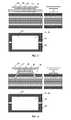
Figure 1 shows a schematic perspective view of a composite structure known in the art formed by six layers with an optical fiber embedded in one of its sides longitudinally to the reinforcement fibers and a cross-sectional view of area A of said structure. -
Figure 2 shows a cross-sectional view of the structure ofFigure 1 in which, using conventional composite structure repair techniques, parts of the surface layer and the second surface have been removed by means of sanding until reaching the embedded optical fiber that has been damaged during the process. -
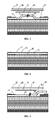
Figure 3 shows elevational, plan and cross-sectional views of a composite structure according to a first embodiment of the invention in which the optical fiber is embedded in a surface layer. -
Figure 4 shows elevational, plan and cross-sectional views of a composite structure according to a second embodiment of the invention in which the optical fiber is embedded inside the structure, leaving only part of it in a surface layer. -
Figure 5 shows similar views to those ofFigures 3 and 4 after the structure consolidation process, in which the optical fiber, the separating films and the outer protective layer are embedded in the structure. -
Figure 6 shows the same view ofFigure 5 after removing the outer protective layer and the outer separating film, the optical fiber being left uncovered. -
Figure 7 shows the same view asFigure 6 in which the previously cut ends of the optical fiber are reconnected after performing the required maintenance operations. -
Figure 8 shows the same view asFigure 7 after the repair process has ended. -
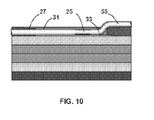
Figure 9 shows a similar view to that ofFigure 7 in which the embedded optical fiber is repaired by means of an external optical fiber line. -
Figure 10 shows the same view asFigure 9 after the repair process has ended. -
Figure 1 shows acomposite structure 11 known in the art formed by a plurality oflayers optical fiber 25 embedded within it that can be part of both a sensor network and part of a data transmission element embedded within it. The integration of thisfiber 25 in thestructure 11 is a complex and delicate process, especially regarding the points of entry of thefiber 25 in said structure, required for its connection to the outside, and the continued existence of these points during the consolidation process. - Furthermore, if for any reason it were necessary to access said
optical fiber 25 to proceed to the maintenance thereof (connection, modification of the line or damage repair while in service), it is possible to reach it by means of composite repair techniques consisting of the local removal of thereinforcement layers fiber 25. Howeveroptical fiber 15 is a very fragile element and said operations for removing parts of the layers of the structure can damage it, as is shown inFigure 2 . - According to the invention, the
structure 11 includes insulation means of theoptical fiber 25 insulating it from the layers in which it is embedded, increasing its possibilities of continued existence and facilitating access thereto at those points susceptible to having maintenance operations (connection, modification of the line or damage repair while in service) performed thereon. - Therefore, and as is shown in
Figures 3-5 , in the case ofstructures 11 withoptical fiber 25 embedded in thesurface layer 13, and at certain points such as the points of entry of theoptical fiber 25 in thestructure 11 through the surface, or at intermediate points chosen as suitable points for performing maintenance tasks, the following insulation means are incorporated: - A
bottom separating film 33 between the structure and theoptical fiber 25 which will facilitate the separation for the optical fiber from the laminate in order to perform maintenance tasks on it after the consolidation process for consolidating the layers of preimpregnated material to form the structure. - A top
separating film 31, like the previous one preferably oriented in the direction of the reinforcement fibers, located on theoptical fiber 25. - A laminar
protective cover 27 having dimensions slightly larger than those of theseparating films - The separating
films protective cover 27 is made of a preimpregnated fiberglass fabric or a similar material. - The
optical fiber 25 cannot be completely embedded in thesurface layer 13 as is shown infigure 4 , it being sufficient that only those areas considered appropriate be embedded. -
Figures 6-7 sequentially illustrate the fundamental steps of a first embodiment of the process of repairing optical fiber in structures herein described. - After removing the
protective cover 27 and the top separatingfilm 31, theoptical fiber 25 that is embedded in thestructure 11 but separated from it by thebottom separating film 33 is removed, and the optical fiber is repaired by means of, for example, joining byfusion 45 of theends optical fiber 25 and the part removed from the structure is returned, remaining in the position shown inFigure 8 . -
Figures 8 and 9 show a second embodiment of the repair process which differs from the first one only in that theoptical fiber 25 repair is carried out, for example, by means of joining byfusion 47 one of itsends 51 to theend 53 of an externaloptical fiber 55, reconducting the optical signal through an alternative path. - In both processes, the repair can include returning the separating
films protective cover 27 by supplying a small amount ofadhesive 29 on the top separatingfilm 33 and applying a consolidation process that is common in repairing composite laminates. - In the preferred embodiment described above any modifications comprised within the scope defined by the following claims can be introduced.
Claims (10)
- A composite structure (11) formed by a plurality of layers (13, 15, 17, 19, 21, 23) including an optical fiber (25) for structural monitoring purposes which is at least partly embedded in said structure (11), characterized in that:a) the embedded part of the optical fiber (25) susceptible to requiring repair is integrated in a surface layer (13) of the structure (11);b) the structure (11) includes insulation means of the optical fiber (25) areas susceptible to repair with respect to the surface layer (13) in which they are integrated.
- A composite structure (11) according to claim 1, characterized in that said insulation means include a top separating film (31) and a bottom separating film (33).
- A composite structure according to claim 2, characterized in that said insulation means also comprise a laminar protective cover (27) arranged on the top separating film (31).
- A composite structure according to claim 2, characterized in that said protective cover (27) is made of preimpregnated fiberglass fabric.
- A composite structure according to claim 4, characterized in that all of the optical fiber (25) is embedded in a surface layer (13) of the structure (11).
- A composite structure according to claim 4, characterized in that the part of the optical fiber (25) not embedded in the surface layer (13) of the structure (11) is embedded in the layer (15) adjacent to it or deeper.
- A process of repairing the optical fiber (25) embedded in a composite structure (11) according to claims 5 or 6, characterized in that it comprises the following steps:a) Removing the protective cover (27) and the top separating film (31) from the optical fiber (25) area in need of repair;b) Extracting the optical fiber (25) area in need of repair from the composite structure (11);c) Repairing the optical fiber (25);d) Relocating the repaired optical fiber (25) area in the composite structure (11);e) Providing a new protective cover (27) on the repaired optical fiber (25) area.
- A process of repairing the optical fiber (25) embedded in a composite structure (11) according to claim 7, characterized in that step d) includes the following additional steps:d') providing a new top separating film (31) on the repaired optical fiber (25) area;d") supplying adhesive (29) on the new separating film (31).
- A process of repairing the optical fiber embedded in a composite structure according to claims 7 or 8, characterized in that the repaired optical fiber (25) area connects ends (41, 43) of optical fiber (25) embedded in the composite structure.
- A process of repairing the optical fiber embedded in a composite structure according to claims 7 or 8, characterized in that the repaired optical fiber (25) area connects one end (51) of optical fiber (25) embedded in the composite structure (11) with one end (53) of an optical fiber (55) located outside the composite structure (11).
Applications Claiming Priority (1)
| Application Number | Priority Date | Filing Date | Title |
|---|---|---|---|
| PCT/ES2005/070167 WO2007063146A1 (en) | 2005-11-30 | 2005-11-30 | Composite material structure having an embedded optical fibre in one of the surface layers thereof and method for connecting and repairing same |
Publications (3)
| Publication Number | Publication Date |
|---|---|
| EP1962123A1 true EP1962123A1 (en) | 2008-08-27 |
| EP1962123A4 EP1962123A4 (en) | 2012-05-09 |
| EP1962123B1 EP1962123B1 (en) | 2014-01-08 |
Family
ID=38087638
Family Applications (1)
| Application Number | Title | Priority Date | Filing Date |
|---|---|---|---|
| EP05825333.7A Expired - Lifetime EP1962123B1 (en) | 2005-11-30 | 2005-11-30 | Composite material structure having an embedded optical fibre in one of the surface layers thereof and method for connecting and repairing the same |
Country Status (8)
| Country | Link |
|---|---|
| US (1) | US7542632B2 (en) |
| EP (1) | EP1962123B1 (en) |
| JP (1) | JP4862048B2 (en) |
| AU (1) | AU2005338589B2 (en) |
| CA (1) | CA2631614C (en) |
| ES (1) | ES2457023T3 (en) |
| IL (1) | IL191870A0 (en) |
| WO (1) | WO2007063146A1 (en) |
Cited By (4)
| Publication number | Priority date | Publication date | Assignee | Title |
|---|---|---|---|---|
| DE102010039153A1 (en) * | 2010-08-10 | 2012-02-16 | Airbus Operations Gmbh | Method for connecting a fiber-optic cable embedded in a fiber composite component with an external optical fiber |
| US8616501B2 (en) | 2008-12-17 | 2013-12-31 | Airbus Operations Gmbh | Pre-installed adaptable supply network for aeroplanes |
| CN108072669A (en) * | 2016-11-11 | 2018-05-25 | 索若德国两合股份有限公司 | For assessing the method and apparatus of the quality of the filamentary material of longitudinal movement |
| DE102019134544A1 (en) * | 2019-12-16 | 2021-06-17 | Deutsches Zentrum für Luft- und Raumfahrt e.V. | Method and system for checking an adhesive bond |
Families Citing this family (8)
| Publication number | Priority date | Publication date | Assignee | Title |
|---|---|---|---|---|
| JP5208759B2 (en) * | 2005-11-30 | 2013-06-12 | エアバス オペレーションズ、ソシエダ リミタダ | Composite structure embedded with optical fiber and repair method thereof |
| DE102007030025B3 (en) * | 2007-06-29 | 2008-10-16 | Airbus Deutschland Gmbh | - Process for repairing damaged region of aircraft fiber bonded component has integrated fiber optics useful in aircraft repair technology gives very strong repair especially effective in minimizing damage to aircraft by stone impact |
| ES2368541B1 (en) * | 2008-10-16 | 2012-09-25 | Rodriser Industria Aeronáutica Española, S.L. | PATCH IMPLEMENTATION PROCEDURE FOR REPAIR OF AIRCRAFT STRUCTURES AND PATCH USED IN THIS PROCEDURE. |
| JP5725455B2 (en) | 2011-06-08 | 2015-05-27 | 国立大学法人 東京大学 | Embedded optical fiber repair method and repair structure of composite structure |
| RU179119U1 (en) * | 2017-09-14 | 2018-04-26 | Российская Федерация, от имени которой выступает ФОНД ПЕРСПЕКТИВНЫХ ИССЛЕДОВАНИЙ | Composite fiber optic sensor exit device |
| ES2925907T3 (en) * | 2019-07-03 | 2022-10-20 | Airbus Operations Slu | Resin flow monitoring system |
| EP4327064B1 (en) * | 2021-04-23 | 2025-12-31 | Politecnico di Milano | HYBRID STRUCTURAL DEVICE WITH SENSORS |
| EP4560941A1 (en) | 2023-11-27 | 2025-05-28 | Airbus Defence and Space GmbH | Photonic transceiver module, periphery device, communication system and apparatus comprising same |
Family Cites Families (25)
| Publication number | Priority date | Publication date | Assignee | Title |
|---|---|---|---|---|
| US3466219A (en) | 1965-08-09 | 1969-09-09 | Us Air Force | Fiber reinforced plastic composite material |
| US3716869A (en) | 1970-12-02 | 1973-02-13 | Nasa | Millimeter wave antenna system |
| US3755713A (en) | 1972-07-25 | 1973-08-28 | Boeing Co | Electrically conductive surface for aircraft |
| FR2383457A1 (en) * | 1977-03-10 | 1978-10-06 | Fort Francois | REPERABLE OPTICAL FIBER CABLE |
| US4221041A (en) | 1978-10-02 | 1980-09-09 | Boeing Commercial Airplane Company | Semi-tubular rivets and method of using |
| US4318954A (en) | 1981-02-09 | 1982-03-09 | Boeing Aerospace Company | Printed wiring board substrates for ceramic chip carriers |
| WO1983000118A1 (en) | 1981-06-30 | 1983-01-20 | Boeing Co | Method of manufacturing a preform from fiber reinforced composite material |
| EP0101766A1 (en) * | 1982-08-23 | 1984-03-07 | AMP INCORPORATED (a New Jersey corporation) | Laminated optical fibre ribbon cable |
| JPS60176006A (en) * | 1984-02-22 | 1985-09-10 | Kanai Hiroyuki | Joining method of optical fibers |
| US5346367A (en) | 1984-12-21 | 1994-09-13 | United Technologies Corporation | Advanced composite rotor blade |
| US4836030A (en) * | 1985-05-20 | 1989-06-06 | Lockheed Corporation | Method of testing composite materials for structural damage |
| US6086975A (en) | 1991-01-16 | 2000-07-11 | The Boeing Company | Lighting protection for electrically conductive or insulating skin and core for honeycomb structure |
| BE1005172A3 (en) * | 1991-08-09 | 1993-05-11 | Bell Telephone Mfg | KONSTRUKTIE for optically coupling, substrate THEM AND METHOD FOR ACHIEVING SUCH KONSTRUKTIE. |
| FR2685081B1 (en) * | 1991-12-11 | 1994-02-04 | Thomson Csf | STRUCTURE WITH INTRINSICALLY DAMAGED CONTROL, MANUFACTURING METHOD AND METHOD OF USE. |
| US5851645A (en) * | 1995-06-07 | 1998-12-22 | Mcdonnell Douglas Corporation | Composite structure having an externally accessible electrical device embedded therein and a related fabrication method |
| US6035084A (en) * | 1997-11-13 | 2000-03-07 | Mcdonell Douglas Corporation | Fiber optic connector and associated method for establishing an optical connection with an optical fiber embedded within a composite structure |
| US6173090B1 (en) * | 1998-10-29 | 2001-01-09 | The United States Of America As Represented By The Secretary Of The Navy | Apparatus for ingress and egress of fiber optic sensor leads from the surface of composite parts and a method for the manufacture thereof |
| JP3699614B2 (en) * | 1999-05-31 | 2005-09-28 | 京セラ株式会社 | Wiring board and manufacturing method thereof |
| JP3243461B2 (en) | 1999-07-30 | 2002-01-07 | 川崎重工業株式会社 | Sandwich structure |
| DE19956394B4 (en) | 1999-11-24 | 2005-02-03 | Airbus Deutschland Gmbh | Process for producing a profile from a hybrid material |
| GB0000415D0 (en) * | 2000-01-11 | 2000-03-01 | British Aerospace | Improvements relating to interfacing embedded optical transmission structures |
| GB0000405D0 (en) * | 2000-01-11 | 2000-03-01 | British Aerospace | Improvements relating to interfacing embedded optical transmission structures |
| EP1342554B1 (en) | 2002-03-08 | 2010-02-03 | Airbus Deutschland GmbH | Method for making textile preforms from textile half-products |
| DE10326422A1 (en) | 2003-06-10 | 2005-01-05 | Eads Deutschland Gmbh | Fiber reinforced plastic profile with internal ribs manufacturing process involves wrapping cores in fiberous material, placing the cores together and wrapping again around the combined profile |
| US7702190B2 (en) * | 2005-04-05 | 2010-04-20 | Agency For Science, Technology And Research | Fiber Bragg grating sensor |
-
2005
- 2005-11-30 ES ES05825333.7T patent/ES2457023T3/en not_active Expired - Lifetime
- 2005-11-30 EP EP05825333.7A patent/EP1962123B1/en not_active Expired - Lifetime
- 2005-11-30 AU AU2005338589A patent/AU2005338589B2/en not_active Ceased
- 2005-11-30 CA CA2631614A patent/CA2631614C/en not_active Expired - Lifetime
- 2005-11-30 JP JP2008542781A patent/JP4862048B2/en not_active Expired - Fee Related
- 2005-11-30 WO PCT/ES2005/070167 patent/WO2007063146A1/en not_active Ceased
-
2006
- 2006-05-25 US US11/441,273 patent/US7542632B2/en not_active Expired - Fee Related
-
2008
- 2008-06-01 IL IL191870A patent/IL191870A0/en active IP Right Grant
Cited By (6)
| Publication number | Priority date | Publication date | Assignee | Title |
|---|---|---|---|---|
| US8616501B2 (en) | 2008-12-17 | 2013-12-31 | Airbus Operations Gmbh | Pre-installed adaptable supply network for aeroplanes |
| DE102010039153A1 (en) * | 2010-08-10 | 2012-02-16 | Airbus Operations Gmbh | Method for connecting a fiber-optic cable embedded in a fiber composite component with an external optical fiber |
| DE102010039153B4 (en) * | 2010-08-10 | 2012-04-19 | Airbus Operations Gmbh | Method for connecting a fiber-optic cable embedded in a fiber composite component with an external optical fiber |
| US9033594B2 (en) | 2010-08-10 | 2015-05-19 | Airbus Operations Gmbh | Method for connecting an optical waveguide, embedded in a fibre composite component, to an external optical waveguide |
| CN108072669A (en) * | 2016-11-11 | 2018-05-25 | 索若德国两合股份有限公司 | For assessing the method and apparatus of the quality of the filamentary material of longitudinal movement |
| DE102019134544A1 (en) * | 2019-12-16 | 2021-06-17 | Deutsches Zentrum für Luft- und Raumfahrt e.V. | Method and system for checking an adhesive bond |
Also Published As
| Publication number | Publication date |
|---|---|
| WO2007063146A1 (en) | 2007-06-07 |
| AU2005338589B2 (en) | 2013-01-31 |
| EP1962123B1 (en) | 2014-01-08 |
| ES2457023T3 (en) | 2014-04-24 |
| EP1962123A4 (en) | 2012-05-09 |
| JP2009517680A (en) | 2009-04-30 |
| CA2631614A1 (en) | 2007-06-07 |
| US20070122099A1 (en) | 2007-05-31 |
| CA2631614C (en) | 2012-11-13 |
| JP4862048B2 (en) | 2012-01-25 |
| US7542632B2 (en) | 2009-06-02 |
| IL191870A0 (en) | 2008-12-29 |
| AU2005338589A1 (en) | 2007-06-07 |
Similar Documents
| Publication | Publication Date | Title |
|---|---|---|
| US7542632B2 (en) | Composite structure with optical fiber embedded in one of its surface layers and a process for its connection and repair | |
| RU2479465C2 (en) | Laminar composite structure | |
| US7405391B2 (en) | Modular sensor for damage detection, manufacturing method, and structural composite material | |
| CN106404065A (en) | Composite material packaged optical fiber grating sensor and manufacturing method thereof | |
| US20110045276A1 (en) | Fiber Reinforced Plastic-Structure and a Method to Produce the Fiber Reinforced Plastic-Structure | |
| CN103391840B (en) | For aircraft or the connector of spacecraft and the manufacture method of connector | |
| US6547448B2 (en) | Embeddable fiber optic connector and associated method | |
| JPH0321853A (en) | Flaw detector by optical fiber | |
| US7706650B2 (en) | Composite structure with embedded optical fiber and a process for its repair | |
| JP2005208000A (en) | Rib structure and method for manufacturing the structure | |
| Kang et al. | Development of fibre optic ingress/egress methods for smart composite structures | |
| CN104199140B (en) | A kind of laminated board fabrication method of pre-buried optical fiber Bragg grating | |
| US20080010942A1 (en) | Stiff panel having composite stiffeners with reduced shock sensitivity | |
| WO2018221597A1 (en) | Composite material blade and method for producing composite material blade | |
| JPH0691816A (en) | Impact damage resistant composite material | |
| US9017511B2 (en) | Aircraft protection device | |
| Ladeveze et al. | Mesomodeling of damage for laminate composites: Application to delamination | |
| CN118254394A (en) | Continuous fiber reinforced composite material embedded with bundled optical fiber and vertical lead-out method | |
| Wood et al. | Design and fabrication considerations for composite structures with embedded fiber optic sensors | |
| US11148392B1 (en) | Enhanced composites via selective interfacial modification | |
| US20120211266A1 (en) | Wiring board and manufacturing method thereof | |
| CN106997072A (en) | A kind of preparation method of fiber grating Material cladding plate for communication equipment | |
| US10197744B2 (en) | Optical fiber connector device for a composite structure, composite structure for an aircraft, and manufacturing method thereof | |
| WO2025168370A1 (en) | Spar cap assembly | |
| WO2026009154A1 (en) | Method and system for manufacturing a structural element in composite material |
Legal Events
| Date | Code | Title | Description |
|---|---|---|---|
| PUAI | Public reference made under article 153(3) epc to a published international application that has entered the european phase |
Free format text: ORIGINAL CODE: 0009012 |
|
| 17P | Request for examination filed |
Effective date: 20080619 |
|
| AK | Designated contracting states |
Kind code of ref document: A1 Designated state(s): AT BE BG CH CY CZ DE DK EE ES FI FR GB GR HU IE IS IT LI LT LU LV MC NL PL PT RO SE SI SK TR |
|
| RIN1 | Information on inventor provided before grant (corrected) |
Inventor name: MENENDEZ MARTIN, JOSE MANUEL |
|
| RAP1 | Party data changed (applicant data changed or rights of an application transferred) |
Owner name: AIRBUS OPERATIONS S.L. |
|
| REG | Reference to a national code |
Ref country code: DE Ref legal event code: R079 Ref document number: 602005042463 Country of ref document: DE Free format text: PREVIOUS MAIN CLASS: G02B0006440000 Ipc: B32B0027000000 |
|
| A4 | Supplementary search report drawn up and despatched |
Effective date: 20120412 |
|
| RIC1 | Information provided on ipc code assigned before grant |
Ipc: G02B 6/44 20060101ALI20120405BHEP Ipc: G01N 21/00 20060101ALI20120405BHEP Ipc: B32B 27/00 20060101AFI20120405BHEP Ipc: B29C 73/26 20060101ALI20120405BHEP Ipc: G01D 5/353 20060101ALI20120405BHEP |
|
| DAX | Request for extension of the european patent (deleted) | ||
| 17Q | First examination report despatched |
Effective date: 20121211 |
|
| GRAP | Despatch of communication of intention to grant a patent |
Free format text: ORIGINAL CODE: EPIDOSNIGR1 |
|
| INTG | Intention to grant announced |
Effective date: 20130801 |
|
| RIN1 | Information on inventor provided before grant (corrected) |
Inventor name: MENENDEZ MARTIN, JOSE MANUEL |
|
| GRAS | Grant fee paid |
Free format text: ORIGINAL CODE: EPIDOSNIGR3 |
|
| GRAA | (expected) grant |
Free format text: ORIGINAL CODE: 0009210 |
|
| AK | Designated contracting states |
Kind code of ref document: B1 Designated state(s): AT BE BG CH CY CZ DE DK EE ES FI FR GB GR HU IE IS IT LI LT LU LV MC NL PL PT RO SE SI SK TR |
|
| REG | Reference to a national code |
Ref country code: GB Ref legal event code: FG4D |
|
| REG | Reference to a national code |
Ref country code: CH Ref legal event code: EP |
|
| REG | Reference to a national code |
Ref country code: IE Ref legal event code: FG4D |
|
| REG | Reference to a national code |
Ref country code: AT Ref legal event code: REF Ref document number: 648443 Country of ref document: AT Kind code of ref document: T Effective date: 20140215 |
|
| REG | Reference to a national code |
Ref country code: DE Ref legal event code: R096 Ref document number: 602005042463 Country of ref document: DE Effective date: 20140220 |
|
| REG | Reference to a national code |
Ref country code: ES Ref legal event code: FG2A Ref document number: 2457023 Country of ref document: ES Kind code of ref document: T3 Effective date: 20140424 |
|
| REG | Reference to a national code |
Ref country code: NL Ref legal event code: VDEP Effective date: 20140108 |
|
| REG | Reference to a national code |
Ref country code: LT Ref legal event code: MG4D |
|
| PG25 | Lapsed in a contracting state [announced via postgrant information from national office to epo] |
Ref country code: LT Free format text: LAPSE BECAUSE OF FAILURE TO SUBMIT A TRANSLATION OF THE DESCRIPTION OR TO PAY THE FEE WITHIN THE PRESCRIBED TIME-LIMIT Effective date: 20140108 Ref country code: IS Free format text: LAPSE BECAUSE OF FAILURE TO SUBMIT A TRANSLATION OF THE DESCRIPTION OR TO PAY THE FEE WITHIN THE PRESCRIBED TIME-LIMIT Effective date: 20140508 |
|
| PG25 | Lapsed in a contracting state [announced via postgrant information from national office to epo] |
Ref country code: SE Free format text: LAPSE BECAUSE OF FAILURE TO SUBMIT A TRANSLATION OF THE DESCRIPTION OR TO PAY THE FEE WITHIN THE PRESCRIBED TIME-LIMIT Effective date: 20140108 Ref country code: NL Free format text: LAPSE BECAUSE OF FAILURE TO SUBMIT A TRANSLATION OF THE DESCRIPTION OR TO PAY THE FEE WITHIN THE PRESCRIBED TIME-LIMIT Effective date: 20140108 Ref country code: CY Free format text: LAPSE BECAUSE OF FAILURE TO SUBMIT A TRANSLATION OF THE DESCRIPTION OR TO PAY THE FEE WITHIN THE PRESCRIBED TIME-LIMIT Effective date: 20140108 Ref country code: PT Free format text: LAPSE BECAUSE OF FAILURE TO SUBMIT A TRANSLATION OF THE DESCRIPTION OR TO PAY THE FEE WITHIN THE PRESCRIBED TIME-LIMIT Effective date: 20140508 Ref country code: FI Free format text: LAPSE BECAUSE OF FAILURE TO SUBMIT A TRANSLATION OF THE DESCRIPTION OR TO PAY THE FEE WITHIN THE PRESCRIBED TIME-LIMIT Effective date: 20140108 |
|
| PG25 | Lapsed in a contracting state [announced via postgrant information from national office to epo] |
Ref country code: LV Free format text: LAPSE BECAUSE OF FAILURE TO SUBMIT A TRANSLATION OF THE DESCRIPTION OR TO PAY THE FEE WITHIN THE PRESCRIBED TIME-LIMIT Effective date: 20140108 Ref country code: BE Free format text: LAPSE BECAUSE OF FAILURE TO SUBMIT A TRANSLATION OF THE DESCRIPTION OR TO PAY THE FEE WITHIN THE PRESCRIBED TIME-LIMIT Effective date: 20140108 |
|
| REG | Reference to a national code |
Ref country code: DE Ref legal event code: R097 Ref document number: 602005042463 Country of ref document: DE |
|
| PG25 | Lapsed in a contracting state [announced via postgrant information from national office to epo] |
Ref country code: EE Free format text: LAPSE BECAUSE OF FAILURE TO SUBMIT A TRANSLATION OF THE DESCRIPTION OR TO PAY THE FEE WITHIN THE PRESCRIBED TIME-LIMIT Effective date: 20140108 Ref country code: CZ Free format text: LAPSE BECAUSE OF FAILURE TO SUBMIT A TRANSLATION OF THE DESCRIPTION OR TO PAY THE FEE WITHIN THE PRESCRIBED TIME-LIMIT Effective date: 20140108 Ref country code: DK Free format text: LAPSE BECAUSE OF FAILURE TO SUBMIT A TRANSLATION OF THE DESCRIPTION OR TO PAY THE FEE WITHIN THE PRESCRIBED TIME-LIMIT Effective date: 20140108 Ref country code: RO Free format text: LAPSE BECAUSE OF FAILURE TO SUBMIT A TRANSLATION OF THE DESCRIPTION OR TO PAY THE FEE WITHIN THE PRESCRIBED TIME-LIMIT Effective date: 20140108 |
|
| PLBE | No opposition filed within time limit |
Free format text: ORIGINAL CODE: 0009261 |
|
| STAA | Information on the status of an ep patent application or granted ep patent |
Free format text: STATUS: NO OPPOSITION FILED WITHIN TIME LIMIT |
|
| PG25 | Lapsed in a contracting state [announced via postgrant information from national office to epo] |
Ref country code: SK Free format text: LAPSE BECAUSE OF FAILURE TO SUBMIT A TRANSLATION OF THE DESCRIPTION OR TO PAY THE FEE WITHIN THE PRESCRIBED TIME-LIMIT Effective date: 20140108 Ref country code: PL Free format text: LAPSE BECAUSE OF FAILURE TO SUBMIT A TRANSLATION OF THE DESCRIPTION OR TO PAY THE FEE WITHIN THE PRESCRIBED TIME-LIMIT Effective date: 20140108 |
|
| 26N | No opposition filed |
Effective date: 20141009 |
|
| REG | Reference to a national code |
Ref country code: DE Ref legal event code: R097 Ref document number: 602005042463 Country of ref document: DE Effective date: 20141009 |
|
| PG25 | Lapsed in a contracting state [announced via postgrant information from national office to epo] |
Ref country code: SI Free format text: LAPSE BECAUSE OF FAILURE TO SUBMIT A TRANSLATION OF THE DESCRIPTION OR TO PAY THE FEE WITHIN THE PRESCRIBED TIME-LIMIT Effective date: 20140108 |
|
| REG | Reference to a national code |
Ref country code: DE Ref legal event code: R119 Ref document number: 602005042463 Country of ref document: DE |
|
| PG25 | Lapsed in a contracting state [announced via postgrant information from national office to epo] |
Ref country code: LU Free format text: LAPSE BECAUSE OF FAILURE TO SUBMIT A TRANSLATION OF THE DESCRIPTION OR TO PAY THE FEE WITHIN THE PRESCRIBED TIME-LIMIT Effective date: 20141130 Ref country code: MC Free format text: LAPSE BECAUSE OF FAILURE TO SUBMIT A TRANSLATION OF THE DESCRIPTION OR TO PAY THE FEE WITHIN THE PRESCRIBED TIME-LIMIT Effective date: 20140108 |
|
| REG | Reference to a national code |
Ref country code: CH Ref legal event code: PL |
|
| GBPC | Gb: european patent ceased through non-payment of renewal fee |
Effective date: 20141130 |
|
| PG25 | Lapsed in a contracting state [announced via postgrant information from national office to epo] |
Ref country code: CH Free format text: LAPSE BECAUSE OF NON-PAYMENT OF DUE FEES Effective date: 20141130 Ref country code: LI Free format text: LAPSE BECAUSE OF NON-PAYMENT OF DUE FEES Effective date: 20141130 |
|
| REG | Reference to a national code |
Ref country code: IE Ref legal event code: MM4A |
|
| REG | Reference to a national code |
Ref country code: FR Ref legal event code: ST Effective date: 20150731 |
|
| PG25 | Lapsed in a contracting state [announced via postgrant information from national office to epo] |
Ref country code: GB Free format text: LAPSE BECAUSE OF NON-PAYMENT OF DUE FEES Effective date: 20141130 Ref country code: IE Free format text: LAPSE BECAUSE OF NON-PAYMENT OF DUE FEES Effective date: 20141130 Ref country code: DE Free format text: LAPSE BECAUSE OF NON-PAYMENT OF DUE FEES Effective date: 20150602 |
|
| PG25 | Lapsed in a contracting state [announced via postgrant information from national office to epo] |
Ref country code: FR Free format text: LAPSE BECAUSE OF NON-PAYMENT OF DUE FEES Effective date: 20141201 |
|
| PG25 | Lapsed in a contracting state [announced via postgrant information from national office to epo] |
Ref country code: BG Free format text: LAPSE BECAUSE OF FAILURE TO SUBMIT A TRANSLATION OF THE DESCRIPTION OR TO PAY THE FEE WITHIN THE PRESCRIBED TIME-LIMIT Effective date: 20140108 |
|
| REG | Reference to a national code |
Ref country code: ES Ref legal event code: FD2A Effective date: 20160603 |
|
| PG25 | Lapsed in a contracting state [announced via postgrant information from national office to epo] |
Ref country code: GR Free format text: LAPSE BECAUSE OF FAILURE TO SUBMIT A TRANSLATION OF THE DESCRIPTION OR TO PAY THE FEE WITHIN THE PRESCRIBED TIME-LIMIT Effective date: 20140409 |
|
| PG25 | Lapsed in a contracting state [announced via postgrant information from national office to epo] |
Ref country code: ES Free format text: LAPSE BECAUSE OF NON-PAYMENT OF DUE FEES Effective date: 20141201 Ref country code: HU Free format text: LAPSE BECAUSE OF FAILURE TO SUBMIT A TRANSLATION OF THE DESCRIPTION OR TO PAY THE FEE WITHIN THE PRESCRIBED TIME-LIMIT; INVALID AB INITIO Effective date: 20051130 Ref country code: TR Free format text: LAPSE BECAUSE OF FAILURE TO SUBMIT A TRANSLATION OF THE DESCRIPTION OR TO PAY THE FEE WITHIN THE PRESCRIBED TIME-LIMIT Effective date: 20140108 |
|
| PGFP | Annual fee paid to national office [announced via postgrant information from national office to epo] |
Ref country code: AT Payment date: 20191121 Year of fee payment: 15 |
|
| REG | Reference to a national code |
Ref country code: AT Ref legal event code: MM01 Ref document number: 648443 Country of ref document: AT Kind code of ref document: T Effective date: 20201130 |
|
| PG25 | Lapsed in a contracting state [announced via postgrant information from national office to epo] |
Ref country code: AT Free format text: LAPSE BECAUSE OF NON-PAYMENT OF DUE FEES Effective date: 20201130 |
|
| PGFP | Annual fee paid to national office [announced via postgrant information from national office to epo] |
Ref country code: IT Payment date: 20211119 Year of fee payment: 17 |
|
| PG25 | Lapsed in a contracting state [announced via postgrant information from national office to epo] |
Ref country code: IT Free format text: LAPSE BECAUSE OF NON-PAYMENT OF DUE FEES Effective date: 20221130 |