EP1962045A1 - Cooling tower with improved drain pan - Google Patents
Cooling tower with improved drain pan Download PDFInfo
- Publication number
- EP1962045A1 EP1962045A1 EP08250426A EP08250426A EP1962045A1 EP 1962045 A1 EP1962045 A1 EP 1962045A1 EP 08250426 A EP08250426 A EP 08250426A EP 08250426 A EP08250426 A EP 08250426A EP 1962045 A1 EP1962045 A1 EP 1962045A1
- Authority
- EP
- European Patent Office
- Prior art keywords
- cooling tower
- sloped
- floor
- sump
- cooling
- Prior art date
- Legal status (The legal status is an assumption and is not a legal conclusion. Google has not performed a legal analysis and makes no representation as to the accuracy of the status listed.)
- Granted
Links
- 238000001816 cooling Methods 0.000 title claims abstract description 75
- XLYOFNOQVPJJNP-UHFFFAOYSA-N water Substances O XLYOFNOQVPJJNP-UHFFFAOYSA-N 0.000 claims abstract description 59
- 150000001875 compounds Chemical class 0.000 claims abstract description 25
- 239000012530 fluid Substances 0.000 claims description 22
- 239000000110 cooling liquid Substances 0.000 claims 1
- 239000003570 air Substances 0.000 description 49
- 239000000498 cooling water Substances 0.000 description 11
- 239000012080 ambient air Substances 0.000 description 8
- 239000007788 liquid Substances 0.000 description 8
- 239000004033 plastic Substances 0.000 description 5
- 229920003023 plastic Polymers 0.000 description 5
- 241000195493 Cryptophyta Species 0.000 description 4
- 238000009825 accumulation Methods 0.000 description 4
- 230000009977 dual effect Effects 0.000 description 4
- 238000000034 method Methods 0.000 description 4
- 230000008569 process Effects 0.000 description 3
- 239000007921 spray Substances 0.000 description 3
- 239000000463 material Substances 0.000 description 2
- 229910052751 metal Inorganic materials 0.000 description 2
- 239000002184 metal Substances 0.000 description 2
- 239000002985 plastic film Substances 0.000 description 2
- 229920000915 polyvinyl chloride Polymers 0.000 description 2
- 239000004800 polyvinyl chloride Substances 0.000 description 2
- 229910001335 Galvanized steel Inorganic materials 0.000 description 1
- 229910052782 aluminium Inorganic materials 0.000 description 1
- XAGFODPZIPBFFR-UHFFFAOYSA-N aluminium Chemical compound [Al] XAGFODPZIPBFFR-UHFFFAOYSA-N 0.000 description 1
- 238000013459 approach Methods 0.000 description 1
- 230000000712 assembly Effects 0.000 description 1
- 238000000429 assembly Methods 0.000 description 1
- 230000015572 biosynthetic process Effects 0.000 description 1
- 230000008859 change Effects 0.000 description 1
- 238000011109 contamination Methods 0.000 description 1
- 238000005260 corrosion Methods 0.000 description 1
- 230000007797 corrosion Effects 0.000 description 1
- 230000000694 effects Effects 0.000 description 1
- 230000008030 elimination Effects 0.000 description 1
- 238000003379 elimination reaction Methods 0.000 description 1
- 239000011152 fibreglass Substances 0.000 description 1
- 239000010408 film Substances 0.000 description 1
- 239000008397 galvanized steel Substances 0.000 description 1
- 230000005484 gravity Effects 0.000 description 1
- 230000006872 improvement Effects 0.000 description 1
- 239000007769 metal material Substances 0.000 description 1
- 239000003595 mist Substances 0.000 description 1
- 239000002245 particle Substances 0.000 description 1
- 230000002265 prevention Effects 0.000 description 1
- 230000001681 protective effect Effects 0.000 description 1
- 239000003507 refrigerant Substances 0.000 description 1
- 229920006395 saturated elastomer Polymers 0.000 description 1
- 239000007787 solid Substances 0.000 description 1
- 238000005507 spraying Methods 0.000 description 1
- 230000007480 spreading Effects 0.000 description 1
- 239000010935 stainless steel Substances 0.000 description 1
- 229910001220 stainless steel Inorganic materials 0.000 description 1
- 239000000126 substance Substances 0.000 description 1
- 239000010409 thin film Substances 0.000 description 1
- 239000003643 water by type Substances 0.000 description 1
- 239000002023 wood Substances 0.000 description 1
Images


Classifications
-
- F—MECHANICAL ENGINEERING; LIGHTING; HEATING; WEAPONS; BLASTING
- F28—HEAT EXCHANGE IN GENERAL
- F28C—HEAT-EXCHANGE APPARATUS, NOT PROVIDED FOR IN ANOTHER SUBCLASS, IN WHICH THE HEAT-EXCHANGE MEDIA COME INTO DIRECT CONTACT WITHOUT CHEMICAL INTERACTION
- F28C1/00—Direct-contact trickle coolers, e.g. cooling towers
- F28C1/04—Direct-contact trickle coolers, e.g. cooling towers with cross-current only
-
- F—MECHANICAL ENGINEERING; LIGHTING; HEATING; WEAPONS; BLASTING
- F28—HEAT EXCHANGE IN GENERAL
- F28C—HEAT-EXCHANGE APPARATUS, NOT PROVIDED FOR IN ANOTHER SUBCLASS, IN WHICH THE HEAT-EXCHANGE MEDIA COME INTO DIRECT CONTACT WITHOUT CHEMICAL INTERACTION
- F28C1/00—Direct-contact trickle coolers, e.g. cooling towers
- F28C1/14—Direct-contact trickle coolers, e.g. cooling towers comprising also a non-direct contact heat exchange
-
- F—MECHANICAL ENGINEERING; LIGHTING; HEATING; WEAPONS; BLASTING
- F28—HEAT EXCHANGE IN GENERAL
- F28F—DETAILS OF HEAT-EXCHANGE AND HEAT-TRANSFER APPARATUS, OF GENERAL APPLICATION
- F28F25/00—Component parts of trickle coolers
- F28F25/02—Component parts of trickle coolers for distributing, circulating, and accumulating liquid
- F28F25/04—Distributing or accumulator troughs
-
- F—MECHANICAL ENGINEERING; LIGHTING; HEATING; WEAPONS; BLASTING
- F28—HEAT EXCHANGE IN GENERAL
- F28F—DETAILS OF HEAT-EXCHANGE AND HEAT-TRANSFER APPARATUS, OF GENERAL APPLICATION
- F28F25/00—Component parts of trickle coolers
- F28F2025/005—Liquid collection; Liquid treatment; Liquid recirculation; Addition of make-up liquid
-
- F—MECHANICAL ENGINEERING; LIGHTING; HEATING; WEAPONS; BLASTING
- F28—HEAT EXCHANGE IN GENERAL
- F28F—DETAILS OF HEAT-EXCHANGE AND HEAT-TRANSFER APPARATUS, OF GENERAL APPLICATION
- F28F2245/00—Coatings; Surface treatments
- F28F2245/08—Coatings; Surface treatments self-cleaning
-
- F—MECHANICAL ENGINEERING; LIGHTING; HEATING; WEAPONS; BLASTING
- F28—HEAT EXCHANGE IN GENERAL
- F28F—DETAILS OF HEAT-EXCHANGE AND HEAT-TRANSFER APPARATUS, OF GENERAL APPLICATION
- F28F2265/00—Safety or protection arrangements; Arrangements for preventing malfunction
- F28F2265/20—Safety or protection arrangements; Arrangements for preventing malfunction for preventing development of microorganisms
-
- Y—GENERAL TAGGING OF NEW TECHNOLOGICAL DEVELOPMENTS; GENERAL TAGGING OF CROSS-SECTIONAL TECHNOLOGIES SPANNING OVER SEVERAL SECTIONS OF THE IPC; TECHNICAL SUBJECTS COVERED BY FORMER USPC CROSS-REFERENCE ART COLLECTIONS [XRACs] AND DIGESTS
- Y02—TECHNOLOGIES OR APPLICATIONS FOR MITIGATION OR ADAPTATION AGAINST CLIMATE CHANGE
- Y02B—CLIMATE CHANGE MITIGATION TECHNOLOGIES RELATED TO BUILDINGS, e.g. HOUSING, HOUSE APPLIANCES OR RELATED END-USER APPLICATIONS
- Y02B30/00—Energy efficient heating, ventilation or air conditioning [HVAC]
- Y02B30/70—Efficient control or regulation technologies, e.g. for control of refrigerant flow, motor or heating
-
- Y—GENERAL TAGGING OF NEW TECHNOLOGICAL DEVELOPMENTS; GENERAL TAGGING OF CROSS-SECTIONAL TECHNOLOGIES SPANNING OVER SEVERAL SECTIONS OF THE IPC; TECHNICAL SUBJECTS COVERED BY FORMER USPC CROSS-REFERENCE ART COLLECTIONS [XRACs] AND DIGESTS
- Y10—TECHNICAL SUBJECTS COVERED BY FORMER USPC
- Y10S—TECHNICAL SUBJECTS COVERED BY FORMER USPC CROSS-REFERENCE ART COLLECTIONS [XRACs] AND DIGESTS
- Y10S261/00—Gas and liquid contact apparatus
- Y10S261/11—Cooling towers
Definitions
- steeply inclined compound sloping floors 170 and 172 are provided on the internal surface of sump 30.
- Such steeply inclined compound sloping floors 170 and 172 extend the entire width of sump 30 in this embodiment, and the presence of such steeply inclined compound sloping floors act to ensure the movement of all water that enters sump 30 toward lower most center sump sections 168 to assure the elimination of any possibility of stagnation of such water in sump 30. This greatly reduces the possibility of formation biological contamination such as algae in the water held in sump 33.
Landscapes
- Engineering & Computer Science (AREA)
- Mechanical Engineering (AREA)
- General Engineering & Computer Science (AREA)
- Physics & Mathematics (AREA)
- Thermal Sciences (AREA)
- Heat-Exchange Devices With Radiators And Conduit Assemblies (AREA)
- Vaporization, Distillation, Condensation, Sublimation, And Cold Traps (AREA)
Abstract
Description
- The present invention relates generally to cooling towers and, more specifically, to a cross flow evaporative heat and mass exchanger used for evaporative fluid cooling. The cross flow arrangement could be a single side or double side entry apparatus. Further, the cooling tower could comprise both a direct fluid cooling arrangement wherein air is passed over fill through which falling liquid is passed thereby cooling the liquid and an indirect cooling section wherein a fluid is passed through a coil and cooled by the liquid, usually water, falling downwardly across the coil thereby providing indirect cooling to a liquid or a gas passing through the coil.
- In an induced draft single cross flow or double cross flow cooling tower, a fan is typically mounted on the roof outlet of the tower. This fan draws or induces air flow inwardly into the cooling tower through a sidewall or opposite sidewalls of the tower. Water or other evaporative liquid to be cooled is pumped to the top of the cooling tower structure and distributed through a series of water distribution nozzles. These nozzles emit a diffused pattern of the water across the top of an appropriately selected fill medium. Such fill most typically comprised of a bundle of generally spaced parallel plastic sheets across each of which the water is dispersed and downwardly passed by gravity. A large surface area across which the water is dispersed on such sheets leads to good cooling by the induced air flow over such sheets. The cooled water is collected in a drain pan or sump and passed through to the desired cooling system wherein it will become heated and then pumped back to the cooling tower.
- As mentioned above, the addition of an indirect cooling section typically in the form of a series of serpentine heat exchange conduits can be provided either above or below the fill sheets. A hot fluid or gas to be cooled or condensed enters the heat exchange conduits through an inlet header at one end of the conduits with the cool fluid exiting the conduit through a header joining the other ends of the conduit.
- A concern in such cross flow cooling towers is the accumulation of algae or other biological contaminates and airborne debris in the drain pan. Such accumulation is usually due to incomplete flow of water through the drain pan. Such development of algae and other biological contaminates is increased with the exposure to sunlight. As the sump or drain pan must catch all flowing water from the cooling section, the design of such sump must address the both collection and drain needs to assure flow of all collected water from the sump to the drain outlet. Water treatment chemicals are used in the cooling tower system to decrease the accumulation of such biological contaminates, but the design of the cooling tower sump and air inlet themselves can improve the resistance of the tower to forming such biological contaminates. Airborne debris that passes through the typical louver arrangement in the air inlet side or sides of the cross flow cooling tower can also contribute to the development of the biological contaminates. Accordingly, an improved design of the air inlet to eliminate the in flow of such airborne debris is also part of the present invention.
- It is an object of the present invention to provide an improved cooling tower using a cross flow air flow relationship with an improved drain sump design.
- It is also an object of the present invention to provide a cooling tower utilizing a cross flow air arrangement with an improved air inlet apparatus to decrease the potential for airborne debris and sunlight to impact the water in the tower. The invention is set out in the independent claims.
- In a mechanical draft cooling tower of the induced draft cross flow type using a single air entry side or two air entry sides with a single fan plenum chamber above the air inlet passages, the water is distributed downwardly onto the fill bundle spreads and trickles down the fill sheets. The water is cooled by the air flow across the fill sheet themselves.
- In such cooling towers, in accordance with the present invention, it is also possible to provide an indirect cooling section wherein a tubular coil heat exchanger comprising a plurality of coil assemblies is provided above or below each fill bundle. The water falling from the direct and indirect cooling sections is collected in a drain sump. In order to assure the complete flow of such collected water through such sump, the ends of the sump are compound sloped to assure that such water is not collected in a stagnant area of the sump. It should be understood that each such sump is usually rectangular, having two ends and two generally longer sides. Steeply sloped sections of the compound slope sump near the end walls aid in assuring the flow of water in the sump to avoid stagnation and debris accumulation as well as sunlight impingement on the standing water. Such steeply sloped sections of the compound slope sump do not detract from the entry of air through the inlets across the fill, but yet allow the water entering the sump to completely flow without collection in any possible stagnant area.
- It is also part of a preferred embodiment to provide an improved design of louvers to the air inlet space of the cooling tower. Such improved louvers are generally of a honeycomb or compound angle blade arrangement which lessen the potential for airborne particles or debris to enter the water falling across the cooling tower fill and enter the collection sump, and aid in the prevention of sunlight impingement on the water.
- In the drawings,
-
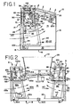
Figure 1 is a side view of an embodiment of a cooling tower of the present invention having a single coil indirect evaporative heat exchange section and a direct heat exchange section; -
Figure 2 is a side view of a second embodiment of the present invention having a dual air inlet cooling tower with two indirect and direct sections; -
Figure 3 is a perspective view of a cooling tower in accordance with an embodiment of the present invention having dual direct cooling sections; -
Figure 4 is a perspective view of the improved drain sump of an embodiment of the present invention; -
Figure 5 is a detailed sectional and partial cross section of the improved slope basin and the improved air inlet of an embodiment of the present invention, and -
Figure 6 is a detailed partial view of an improved air inlet of an embodiment of the present invention. - Referring to
Figure 1 of the drawings, theheat exchange apparatus 10 in accordance with the invention is shown as a closed-circuit cooling tower. Generally,apparatus 10. includes an enclosure structure which contains a multi-circuit indirect evaporativefluid cooling section 50, a direct evaporativeheat exchange section 90, a lowermost evaporativeliquid collection sump 30, and an uppermost distribution means 36 for spraying an evaporative liquid downwardly throughapparatus 10, and a fan means 24 for moving a stream of air through each of theheat exchange sections Fan 24 can either be induced or forced draft centrifugal fan or a common propeller type fan, any of said fan choices requiring fan motor 25 to power them. Again referring toFigure 1 , motor 25 can be mounted withinenclosure passageway 15 if an appropriate wet condition motor casing or a protective cover is used, or it can be mounted on the outside of the structure if desired. Here it is shown in the air stream inmoisture proof box 200. - It is important to understand that
apparatus 10 has many applications in the heat exchange field and that each application will use all of the same above-mentioned elements, although the operation of those elements might vary slightly from one type of application to the other. For example,apparatus 10 may be used to cool a single phase, sensible fluid such as water, which is flowing within an externally-supplied closed circuit system, or it may be sued to desuperheat and condense a multi-phase, sensible and latent fluid such as a refrigerant gas, also supplied from an external closed-circuit system. - In accordance with one embodiment of the present invention illustrated in
Figure 1 , the enclosurestructure comprising apparatus 10 is shown with a generally rectangular shape which includes anupper roof surface 12, abase 18, afront wall 14, arear wall 16, a first side wall 20 and a second side wall 22. The side walls 20, 22 andrear wall 16 are continuously solid panel members made from materials such a sheet metal, fiberglass, plastic, or the like, and these walls have corrosion resistant properties as doesfront wall 14 androof surface 12. - The rectangular enclosure structure of
Figure 1 contains an indirectheat exchange section 50, which is comprised of asingle coil assembly 52, superposed above the direct evaporativeheat exchange section 90. The indirectheat exchange section 50 is typically of a rectangular shape, having aninboard side 51, anoutboard side 57, atop side 53 and abottom side 55. The indirect heat exchangesection coil assembly 52 receives a flowing hot fluid to be cooled from an offsite process, and it is cooled in this section by a combination of indirect sensible heat exchange and a direct evaporative heat exchange. The evaporative liquid, which is usually cooling water, is sprayed downwardly by distribution means 36 onto the indirect section, thereby exchanging indirect sensible heat with the fluid to be cooled, while the stream of ambient air enteringprimary air inlet 100, evaporatively cools the water as the two mediums move downwardly throughcoil system 52. In this particular embodiment the entering air stream is shown entering and flowing in a direction which is parallel or concurrent with the direction of cooling water, although the air flow stream is not limited to any particular flow pattern, as will become evident later on where a crosscurrent air flow pattern will be explained. Once the air and water cooling mediums reachbottom side 55 ofindirect section 50, they split, with the air system being pulled into plenum 105 and then intopassageway 15 byfan 24,while the water gravitationally descends into directheat exchange section 90. The air is then discharged fromapparatus 10 through thefan cylinder 26 while the water is cooled in the direct heat exchange section as will be explained shortly. It is also important to note that the air stream entering inlet 100 supplies air that will only be used for cooling purposes in the indirect heat exchange section, regardless of the actual air flow pattern through said section. - The direct evaporative
heat exchange section 90 functions to cool the water that is heated and descending from the indirectheat exchange section 50. Directevaporative heat exchange 90 is comprised of an array of tightly-spaced, parallel,plastic sheets 93 which formfill bundle 92. The hot water received byfill bundle 92 fromindirect section 50 is distributed across eachfill sheet 93 so that a source of outside ambient air which enterssecondary air inlet 102, evaporatively cools the hot water descending the sheets. Here, the ambient air stream is shown enteringdirect section 90 in a crosscurrent fashion to the descending hot water draining through thefill bundle 92, although other air flow schemes can be used, as will be seen later. Theplastic fill sheets 93 are usually hung frombeams 96 that are connected to and traverse sidewalls 20 and 22. Eachsheet 93 has a generally continuous, waved pattern of grooves running the entire length of the sheet to aid in spreading the downflowing hot water into a thin film, thereby providing a larger exposed surface area for the air stream to interact with and evaporatively cool. Fillsheets 93 are preferably made from a polyvinyl chloride material, although other types of plastics could be used. Secondaryambient air inlet 102 provides ambient air that is strictly dedicated for evaporative cooling purposes in the direct heat exchange section only. - As further seen from
Figure 1 asecondary entryway 102 is covered with a honeycombed orvertical blade structure 28. Such honeycombed orvertical blade structure 28 is an improvement over the typical louver arrangement. Such honeycomb or vertical blade structure includes openings that readily allow air flow but keep air borne debris from enteringindirect cooling tower 90 and fillbundle 92. This honeycomb or vertical blade design is further described inFigure 5 and 6 below. The ambient air entering throughhoneycomb 28 initially flows across thesecondary air plenum 103 before enteringfill bundle 92 in a crosswise or crosscurrent fashion to the hot water downwardly gravitating through theplastic fill sheets 93. As mentioned, the stream of cold air passing over the film of hot water evaporatively removes heat from the water, thereby cooling the hot water by well known evaporative effects. The heated air existingevaporative cooling section 90 then passes throughsecondary drift eliminator 49 before enteringpassageway 15, where it is forced byfan 24 to upwardly change directions for discharge to the atmosphere throughfan cylinder 26. Since the air leaving the direct waterevaporative cooling section 90 becomes saturated with moisture absorbed from the cooling water, thesecondary drift eliminator 49 is interposed between thefill bundle 92 andpassageway 15 to facilitate in removing the water droplets entrapped in the air stream.Drift eliminator 49 it typically comprised of closely spaced metal, plastic or wood slats or louvers which permit air flow thererthrough, but will collect the fine water droplets in the air. The collected water then gravitates downeliminator 49, directly intounderlying collection sump 30 for recirculation. - As seen in
Figure 1 , theentire base 18 ofapparatus 10 is substantially comprised of awater collection sump 30 which is typically disposed only below direct evaporativeheat exchange section 90, although it truly depends upon how the components are arranged within the structure ofapparatus 10, where the direct and indirect sections are side-by-side. The side-by-side or indirect-over-direct arrangements merely emphasize that the most important feature of the present invention is that the heated cooling water descending from the direct evaporativeheat exchange section 90 is allowed to mix insump 30 so that it can attain a uniform temperature before being pumped for use again in the indirectheat exchanger section 50. As seen, vertically extending recycle piping 34 operably connects cooling water distribution means 36 withpump 32 andsump 30.Pump 32 is arranged outside ofsump 30 near the corner offront wall 14 so that it can be easily serviced. - Distribution means 36 is generally located above the
single coil assembly 52 of indirectevaporative cooling section 50, which is also in positional relationship with primaryambient air inlet 100. Distribution means 36 consists of identical coolingwater distribution legs tower 10 in a spaced, parallel relationship from each other and fromfront wall 14. Eachdistribution leg spray nozzles 46 attached along the bottom of the pipe for evenly distributing the cooling water across thetop side 53 of indirect evaporativeheat exchange section 50 and generally across theprimary air inlet 100. Depending upon the heat exchange capacity required fromapparatus 10, the number of water distribution legs can vary from 1 to 5 legs per indirectevaporative coil section 52, with the length of each leg varying between 3-24 feet. Typically, the number ofnozzles 46 percoil assembly 52 ofindirect section 50 will vary between 9-180 nozzles, also depending upon the tower capacity. Likewise, pump 32 is sized according to tower capacity such that the continuous supply of cooling water pumped tospray nozzles 46 will produce a fine spray of water across the entire span of theprimary air inlet 100 and hence, across thesingle coil assembly 52. Similarly, anupper drift eliminator 48 is interposed betweenside outlet opening 106, plenum 105 andpassageway 15 to remove the water droplets entrapped by the primary air stream while evaporatively cooling the water descending through indirectheat exchange section 50.Pan 47 is disposed belowupper drift eliminator 48 for collecting the water frommist eliminator 48 and gravitationally dispensing it uponfill sheet bundle 92. It is to be understood that the opening which defines primaryambient air inlet 100 has a dimensional length and width equal to that of the indirectevaporative cooling section 50 no matter where the entry is located. FromFigure 1 it is seen that the entering air stream initially approachesentryway 100 generally perpendicular to thetop side 53 of indirectheat exchange section 50, substantially concurrent with the water sprayed downwardly from distribution means 36. - Referring now to
Figure 2 of the drawings, a series flow, dualcoiled assembly 52 and 52A is incorporated intoapparatus 10 with a split cooling water system. This apparatus is generally known in the art as a closed loop, double coiled cooling tower and represents the preferred dual coiled embodiment. Each of the tower ends 6 and 8 contain the exact same elements within each respective tower half as are contained within the structure of the single coiled, preferred embodiment ofFigure 1 . As seen, the hot fluid to be cooled is initially supplied to thefirst tower end 6 through supply piping 75W. The hot fluid generally enters and travels upwardly as previously explained for the single coiled apparatus, however, instead of exiting indirectheat exchange section 50 and returning to the offsite process, the fluid leavesindirect section 50 through piping 85W and is communicated to the inlet header 75a on the secondindirect coil assembly 52a of the second indirectheat exchange section 50A oftower half 8. Once again, the fluid travels upwardly through indirect heat exchange section piping 52a and cooling capacity is further increased by an additional 10% as compared to the same unit with the heat exchange sections piped in parallel. Once cooled within indirect heat exchange section piping 52a, the fluid is then returned to the offsite process through discharge piping 85C. All methods of heat exchange within each of the heat exchange sections on eachtower half tower half tower half - Referring now to
Figure 3 of the drawings, an embodiment of the present invention is shown in a perspective view. This perspective view is similarly numbered features ofFigure 2 are set forth inFigure 3 , and will not be described in detail here. Indirect heat exchange section is shown generally at 50, although it should be understood that the features of the present invention could apply to a cooling tower that does not include an indirect heat exchange section. A directheat exchange section 90 is seen to includefill sheet bundle 92 which is visible with part ofhoneycomb inlet 28 broken away to show portion offill sheet 92. Further, collection basin is shown generally at 30 which will be described further.Collection basin 30 is seen to be generally rectangular in shape, having ends 150 and 152, withsides - Referring now to
Figure 4 , basin orsump 30 is shown in detail as a generally rectangular structure having ends 150 and 152 withsides sump 30 is comprised of galvanized steel, but can be comprised of aluminum, stainless steel, or non-metallic materials. Compound sloped bottom 160 is seen to be comprised of a series ofsections center 168 on one side ofsump 30. Similar sections are on the other side ofsump 30. A drain exits fromcenter sump section 168. - In order to decrease the possibility of airborne debris and biological contaminates such as algae building up in
sump 30 while it holds water drained from directcooling tower section 90, steeply inclinedcompound sloping floors sump 30. Such steeply inclinedcompound sloping floors sump 30 in this embodiment, and the presence of such steeply inclined compound sloping floors act to ensure the movement of all water that enterssump 30 toward lower mostcenter sump sections 168 to assure the elimination of any possibility of stagnation of such water insump 30. This greatly reduces the possibility of formation biological contamination such as algae in the water held in sump 33. - Referring now to
Figure 5 of the drawings, a detailed end view, in partial cross section, is shown ofsump 30.Sump 30 is seen to be comprised of anend wall 150, withcompound sloping floor 172 forming part of the actual collection section ofsump 30. It is seen that fill 92 may extend downwardly intosump 30. Further, the slight incline ofbottom section 162 is seen to be extended to adjacentbottom sump section 164 to assure a downwardly flow and collection ofwaters entering sump 30 toward center lowermost sump section 168. Further , it is seen that the angled incline of the internal sumpcompound sloping floor 172 greatly reduces the possibility of any stagnation or collection of water withinsump 30 that would not be moved toward center lowermost section 168 and outwardly through the drain insump 30. The preferred angle of internal sump first part of thecompound sloping floor 172 is about 50° from the horizontal, with angles from 25 to 70° being functional as well. - Also shown in
Figures 5 and 6 is a view of honeycomb or vertical bladeend wall inlet 28. It is seen that such structure, which is generally of PVC, provides a ready inlet of air intoindirect cooling section 90 and fill 92. Such honeycomb orvertical blade structure 28 is seen to greatly reduce the potential for airborne debris to enterdirect cooling section 90. Honeycomb orvertical blade structure 28 is generally comprised of a plurality of vertically alignedslats 228 that have openings therein to allow the passage of air therethrough yet block the passage of airborne debris.
Claims (13)
- A mechanical draft direct and indirect cooling tower comprising
at least one direct section (90) having a plurality of fill sheets (93) wherein a fluid is distributed over the fill sheets,
a fan (24) to draw air into the cooling tower across the fill sheets thus cooling the fluid flowing over the fill sheets,
the fluid distributed over the fill sheets falling from the fill sheets into a collection sump (30),
the collection sump (30) having a generally rectangular configuration with two parallel end walls (150, 152) and two parallel side walls (154, 156), a sloped floor (160) with at least two different slopes, and a drain, wherein the sloped floor has a compound slope adjacent at least one end wall and in contact with the side walls such that a significant portion of the compound sloped floor includes a first part located above an operating sump water level and wherein the sloped floor in the first part is sloped to prevent the settling of dirt and debris. - The cooling tower of claim 1
wherein the first part of the sloped floor is sloped 25 to 70° from the horizontal. - The cooling tower of claim 1
wherein the first part of the sloped floor is sloped 40 to 60° from the horizontal. - The cooling tower of any preceding claim
further comprising a second part of the compound slope floor sloped towards a drain but at a lesser angle from the horizontal than the first part of the compound slope floor. - The cooling tower of any preceding claim
wherein at the operating sump water level, less than three inches of horizontal water surface prior to the air entrance to the fill section is located above the surface of the first part of the compound slope floor. - The cooling tower of any preceding claim
wherein a louver arrangement (28) is provided through which air is drawn into the cooling tower, the louver arrangement comprising aligned slats that block the passage of airborne debris and sunlight into the cooling tower. - A mechanical draft cooling tower comprising
at least one direct cooling section (90) having a plurality of fill sheets (93)
wherein a fluid is distributed to flow over the fill sheets,
a fan (24) to draw air through an air inlet into the cooling tower across the fill sheets thus cooling the fluid flowing over the fill sheets,
the fluid distributed over the fill sheets falling from the fill sheets into a collection sump (30),
the collection sump having a generally rectangular configuration with two parallel end walls (150, 152) and two parallel side walls (154, 156), a sloped floor with a least two different slopes, and a drain, wherein the sloped floor has a compound slope near at least one end wall and in contact with the side walls such that a significant portion of the compound sloped floor includes a first part in front of the air inlet located above an operating sump water level and wherein the sloped floor in the first part of the compound sloped floor is sloped to prevent the settling of dirt and debris. - The cooling tower of claim 7
wherein the first part of the compound sloped floor is sloped 25 to 70° from the horizontal. - The cooling tower of claim 7
wherein the first part of the sloped floor is sloped 40 to 60° from the horizontal. - The cooling tower of claim 7, 8 or 9
further comprising a second part of the compound slope floor sloped towards a drain but at a lesser angle from the horizontal than the first part of the compound slope floor. - The cooling tower of any of claims 7 to 10
wherein at the operating sump water level, less than three inches of horizontal water surface prior to the air entrance to the fill section is located above the surface of the first part of the compound slope floor. - The cooling tower of any of claims 7 to 11
wherein a louver arrangement (28) is provided through which air is drawn into the cooling tower, the louver arrangement comprising aligned slats that block the passage of airborne debris and sunlight into the cooling tower. - A cooling liquid collection sump (30) provided in the base of a cooling tower, the sump having a compound sloped floor with a more steeply inclined end part or parts (172) sloped at an angle of 25 to 70° from the horizontal to encourage fluid landing adjacent end(s) of the sump to flow towards a drain in a center or opposite end region thereof.
Applications Claiming Priority (1)
| Application Number | Priority Date | Filing Date | Title |
|---|---|---|---|
| US11/595,595 US7802774B2 (en) | 2007-02-20 | 2007-02-20 | Cooling tower air inlet and drain pan |
Publications (2)
| Publication Number | Publication Date |
|---|---|
| EP1962045A1 true EP1962045A1 (en) | 2008-08-27 |
| EP1962045B1 EP1962045B1 (en) | 2010-04-21 |
Family
ID=39357227
Family Applications (1)
| Application Number | Title | Priority Date | Filing Date |
|---|---|---|---|
| EP08250426A Active EP1962045B1 (en) | 2007-02-20 | 2008-02-05 | Cooling tower with improved drain pan |
Country Status (9)
| Country | Link |
|---|---|
| US (1) | US7802774B2 (en) |
| EP (1) | EP1962045B1 (en) |
| KR (1) | KR20080077543A (en) |
| CN (1) | CN101251340A (en) |
| BR (1) | BRPI0704220A (en) |
| DE (1) | DE602008001002D1 (en) |
| ES (1) | ES2340641T3 (en) |
| MX (1) | MX2007013617A (en) |
| MY (1) | MY147980A (en) |
Families Citing this family (10)
| Publication number | Priority date | Publication date | Assignee | Title |
|---|---|---|---|---|
| EP3207323A4 (en) | 2014-07-21 | 2018-01-24 | Prime Datum Development Company, LLC | Cooling schemes and methods for cooling tower motors |
| CA2999915C (en) * | 2015-09-23 | 2024-02-20 | Composite Cooling Solutions, L.P. | Hybrid wet/dry cooling tower and improved fill material for cooling tower |
| CN107202501B (en) * | 2016-03-18 | 2023-04-14 | 厦门嘉达环保科技有限公司 | Centralized cooling tower ventilation noise reduction system |
| US11029093B2 (en) * | 2017-03-30 | 2021-06-08 | Baltimore Aircoil Company, Inc. | Cooling tower with direct and indirect heat exchanger |
| CN108168331A (en) * | 2018-02-11 | 2018-06-15 | 广州览讯科技开发有限公司 | A kind of centrifugation exhausting single admission top air-out cross flow cooling tower |
| US11668534B2 (en) | 2018-12-13 | 2023-06-06 | Baltimore Aircoil Company, Inc. | Fan array fault response control system |
| EP3942241A4 (en) | 2019-03-19 | 2022-11-23 | Baltimore Aircoil Company, Inc. | Heat exchanger having plume abatement assembly bypass |
| JP2023505766A (en) | 2019-12-11 | 2023-02-13 | バルチモア、エアコイル、カンパニー、インコーポレーテッド | Heat Exchanger System with Machine Learning Based Optimization |
| US11859924B2 (en) | 2020-05-12 | 2024-01-02 | Baltimore Aircoil Company, Inc. | Cooling tower control system |
| EP4211413A4 (en) * | 2021-08-13 | 2023-08-30 | Evapco, INC. | Induced draft heat rejection equipment with top mounted backward-curved centrifugal fans |
Citations (4)
| Publication number | Priority date | Publication date | Assignee | Title |
|---|---|---|---|---|
| US3052105A (en) * | 1960-06-15 | 1962-09-04 | Carrier Corp | Heat exchanger |
| GB1558533A (en) * | 1976-09-02 | 1980-01-03 | Stichting Inst Mech | Contacting device for gas and liquid |
| EP1035395A2 (en) * | 1999-03-08 | 2000-09-13 | Baltimore Aircoil Company, Inc. | Rigid evaporative heat exchangers |
| US20030145619A1 (en) * | 2002-02-01 | 2003-08-07 | Mac Word | Apparatus and method for closed circuit cooling tower with corrugated metal tube elements |
Family Cites Families (10)
| Publication number | Priority date | Publication date | Assignee | Title |
|---|---|---|---|---|
| SE302778B (en) * | 1963-07-04 | 1968-08-05 | C Munters | |
| SE311371B (en) * | 1966-01-26 | 1969-06-09 | Munters C | |
| US3437319A (en) * | 1968-05-20 | 1969-04-08 | Baltimore Aircoil Co Inc | Evaporative heat exchanger with airflow reversal baffle |
| US3878273A (en) * | 1972-10-13 | 1975-04-15 | James H Anderson | Plural water/air contact for cooling water cycle |
| US4774033A (en) * | 1987-03-17 | 1988-09-27 | Energair Research And Development | Gas liquid tower structure |
| JP2580991B2 (en) * | 1993-12-29 | 1997-02-12 | 石川島播磨重工業株式会社 | Cooling method of cooling water and cooling water tower |
| US6070860A (en) * | 1998-08-14 | 2000-06-06 | The Marley Cooling Tower Company | Crossflow water cooling tower having structure allowing air flow through water distribution system |
| US6497401B2 (en) * | 1999-08-23 | 2002-12-24 | Delta Cooling Towers, Inc. | Molded cooling tower |
| US6938885B2 (en) * | 2000-08-11 | 2005-09-06 | Kyung In Machinery Co., Ltd. | Hybrid type cooling tower |
| US6598862B2 (en) * | 2001-06-20 | 2003-07-29 | Evapco International, Inc. | Evaporative cooler |
-
2007
- 2007-02-20 US US11/595,595 patent/US7802774B2/en active Active
- 2007-09-28 MY MYPI20071665A patent/MY147980A/en unknown
- 2007-10-23 CN CNA2007101674073A patent/CN101251340A/en active Pending
- 2007-10-30 MX MX2007013617A patent/MX2007013617A/en active IP Right Grant
- 2007-11-01 KR KR1020070111123A patent/KR20080077543A/en not_active Application Discontinuation
- 2007-11-14 BR BRPI0704220-5A patent/BRPI0704220A/en not_active Application Discontinuation
-
2008
- 2008-02-05 ES ES08250426T patent/ES2340641T3/en active Active
- 2008-02-05 DE DE602008001002T patent/DE602008001002D1/en active Active
- 2008-02-05 EP EP08250426A patent/EP1962045B1/en active Active
Patent Citations (4)
| Publication number | Priority date | Publication date | Assignee | Title |
|---|---|---|---|---|
| US3052105A (en) * | 1960-06-15 | 1962-09-04 | Carrier Corp | Heat exchanger |
| GB1558533A (en) * | 1976-09-02 | 1980-01-03 | Stichting Inst Mech | Contacting device for gas and liquid |
| EP1035395A2 (en) * | 1999-03-08 | 2000-09-13 | Baltimore Aircoil Company, Inc. | Rigid evaporative heat exchangers |
| US20030145619A1 (en) * | 2002-02-01 | 2003-08-07 | Mac Word | Apparatus and method for closed circuit cooling tower with corrugated metal tube elements |
Also Published As
| Publication number | Publication date |
|---|---|
| US20080197515A1 (en) | 2008-08-21 |
| EP1962045B1 (en) | 2010-04-21 |
| KR20080077543A (en) | 2008-08-25 |
| DE602008001002D1 (en) | 2010-06-02 |
| ES2340641T3 (en) | 2010-06-07 |
| US7802774B2 (en) | 2010-09-28 |
| MY147980A (en) | 2013-02-28 |
| BRPI0704220A (en) | 2008-10-07 |
| CN101251340A (en) | 2008-08-27 |
| MX2007013617A (en) | 2009-02-19 |
Similar Documents
| Publication | Publication Date | Title |
|---|---|---|
| EP1962045B1 (en) | Cooling tower with improved drain pan | |
| US9644904B2 (en) | Direct forced draft fluid cooler/cooling tower and liquid collector therefor | |
| EP0738861B1 (en) | Method of exchanging heat and heat exchange apparatus with a direct heat exchange section and an indirect heat exchange section | |
| US7779898B2 (en) | Heat transfer tube assembly with serpentine circuits | |
| EP1409120B1 (en) | Evaporative cooler | |
| US7484718B2 (en) | Cooling tower with direct and indirect cooling sections | |
| EP0629831B1 (en) | Combination direct and indirect closed circuit evaporative heat exchanger | |
| US11255620B2 (en) | Water collection/deflection arrangement | |
| JP6580661B2 (en) | cooling tower | |
| EP3201552B1 (en) | Compact heat exchange system and method of cooling | |
| US20130081414A1 (en) | Evaporative cooler | |
| US10852079B2 (en) | Apparatus for cooling liquid and collection assembly therefor | |
| GB2160963A (en) | Dew-point cooler | |
| JP7121739B2 (en) | cooling tower | |
| US11844541B2 (en) | Cooling tower | |
| JP3014219U (en) | Cross-flow cooling tower with white smoke prevention function | |
| AU2002310244B2 (en) | Evaporative cooler | |
| Watt | Air Washer Evaporate Coolers | |
| AU2002310244A1 (en) | Evaporative cooler |
Legal Events
| Date | Code | Title | Description |
|---|---|---|---|
| PUAI | Public reference made under article 153(3) epc to a published international application that has entered the european phase |
Free format text: ORIGINAL CODE: 0009012 |
|
| AK | Designated contracting states |
Kind code of ref document: A1 Designated state(s): AT BE BG CH CY CZ DE DK EE ES FI FR GB GR HR HU IE IS IT LI LT LU LV MC MT NL NO PL PT RO SE SI SK TR |
|
| AX | Request for extension of the european patent |
Extension state: AL BA MK RS |
|
| 17P | Request for examination filed |
Effective date: 20090121 |
|
| 17Q | First examination report despatched |
Effective date: 20090227 |
|
| AKX | Designation fees paid |
Designated state(s): BE DE ES FR GB IT |
|
| GRAP | Despatch of communication of intention to grant a patent |
Free format text: ORIGINAL CODE: EPIDOSNIGR1 |
|
| GRAS | Grant fee paid |
Free format text: ORIGINAL CODE: EPIDOSNIGR3 |
|
| GRAA | (expected) grant |
Free format text: ORIGINAL CODE: 0009210 |
|
| AK | Designated contracting states |
Kind code of ref document: B1 Designated state(s): BE DE ES FR GB IT |
|
| REG | Reference to a national code |
Ref country code: GB Ref legal event code: FG4D |
|
| REF | Corresponds to: |
Ref document number: 602008001002 Country of ref document: DE Date of ref document: 20100602 Kind code of ref document: P |
|
| REG | Reference to a national code |
Ref country code: ES Ref legal event code: FG2A Ref document number: 2340641 Country of ref document: ES Kind code of ref document: T3 |
|
| PLBE | No opposition filed within time limit |
Free format text: ORIGINAL CODE: 0009261 |
|
| STAA | Information on the status of an ep patent application or granted ep patent |
Free format text: STATUS: NO OPPOSITION FILED WITHIN TIME LIMIT |
|
| 26N | No opposition filed |
Effective date: 20110124 |
|
| REG | Reference to a national code |
Ref country code: FR Ref legal event code: PLFP Year of fee payment: 9 |
|
| REG | Reference to a national code |
Ref country code: FR Ref legal event code: PLFP Year of fee payment: 10 |
|
| REG | Reference to a national code |
Ref country code: FR Ref legal event code: PLFP Year of fee payment: 11 |
|
| PGFP | Annual fee paid to national office [announced via postgrant information from national office to epo] |
Ref country code: FR Payment date: 20230119 Year of fee payment: 16 Ref country code: ES Payment date: 20230301 Year of fee payment: 16 |
|
| PGFP | Annual fee paid to national office [announced via postgrant information from national office to epo] |
Ref country code: IT Payment date: 20230120 Year of fee payment: 16 Ref country code: GB Payment date: 20230121 Year of fee payment: 16 Ref country code: DE Payment date: 20230119 Year of fee payment: 16 Ref country code: BE Payment date: 20230119 Year of fee payment: 16 |
|
| PGFP | Annual fee paid to national office [announced via postgrant information from national office to epo] |
Ref country code: ES Payment date: 20240301 Year of fee payment: 17 |