EP1962027A1 - Indoor device of air conditioner - Google Patents
Indoor device of air conditioner Download PDFInfo
- Publication number
- EP1962027A1 EP1962027A1 EP06833005A EP06833005A EP1962027A1 EP 1962027 A1 EP1962027 A1 EP 1962027A1 EP 06833005 A EP06833005 A EP 06833005A EP 06833005 A EP06833005 A EP 06833005A EP 1962027 A1 EP1962027 A1 EP 1962027A1
- Authority
- EP
- European Patent Office
- Prior art keywords
- harness
- holding member
- harness holding
- body casing
- indoor unit
- Prior art date
- Legal status (The legal status is an assumption and is not a legal conclusion. Google has not performed a legal analysis and makes no representation as to the accuracy of the status listed.)
- Withdrawn
Links
Images



Classifications
-
- F—MECHANICAL ENGINEERING; LIGHTING; HEATING; WEAPONS; BLASTING
- F24—HEATING; RANGES; VENTILATING
- F24F—AIR-CONDITIONING; AIR-HUMIDIFICATION; VENTILATION; USE OF AIR CURRENTS FOR SCREENING
- F24F13/00—Details common to, or for air-conditioning, air-humidification, ventilation or use of air currents for screening
- F24F13/20—Casings or covers
-
- F—MECHANICAL ENGINEERING; LIGHTING; HEATING; WEAPONS; BLASTING
- F24—HEATING; RANGES; VENTILATING
- F24F—AIR-CONDITIONING; AIR-HUMIDIFICATION; VENTILATION; USE OF AIR CURRENTS FOR SCREENING
- F24F1/00—Room units for air-conditioning, e.g. separate or self-contained units or units receiving primary air from a central station
- F24F1/0007—Indoor units, e.g. fan coil units
- F24F1/0059—Indoor units, e.g. fan coil units characterised by heat exchangers
- F24F1/0063—Indoor units, e.g. fan coil units characterised by heat exchangers by the mounting or arrangement of the heat exchangers
-
- F—MECHANICAL ENGINEERING; LIGHTING; HEATING; WEAPONS; BLASTING
- F24—HEATING; RANGES; VENTILATING
- F24F—AIR-CONDITIONING; AIR-HUMIDIFICATION; VENTILATION; USE OF AIR CURRENTS FOR SCREENING
- F24F1/00—Room units for air-conditioning, e.g. separate or self-contained units or units receiving primary air from a central station
- F24F1/0007—Indoor units, e.g. fan coil units
- F24F1/0043—Indoor units, e.g. fan coil units characterised by mounting arrangements
- F24F1/0057—Indoor units, e.g. fan coil units characterised by mounting arrangements mounted in or on a wall
-
- F—MECHANICAL ENGINEERING; LIGHTING; HEATING; WEAPONS; BLASTING
- F24—HEATING; RANGES; VENTILATING
- F24F—AIR-CONDITIONING; AIR-HUMIDIFICATION; VENTILATION; USE OF AIR CURRENTS FOR SCREENING
- F24F13/00—Details common to, or for air-conditioning, air-humidification, ventilation or use of air currents for screening
- F24F13/20—Casings or covers
- F24F2013/207—Casings or covers with control knobs; Mounting controlling members or control units therein
Definitions
- the present invention relates to an indoor unit for air conditioners.
- harnesses In assembling of indoor units for air conditioners, there is a tendency that the handling of wire/cable harnesses (hereinafter, referred to simply as harnesses) becomes more and more complex with recent years' increasingly higher functions.
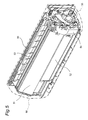
- Fig. 5 shows a perspective view of an air-conditioner indoor unit according to a prior art.
- a state in which a front panel 56 has been removed is shown.
- a first heat exchange part 51 and a second heat exchange part 52 are placed on the front side of a bottom frame 50, and a third heat exchange part 53 is placed on the rear side of the first heat exchange part 51 and the second heat exchange part 52.
- the first heat exchange part 51, the second heat exchange part 52 and the third heat exchange part 53 constitute an indoor heat exchanger.
- an electrical part box 55 is placed at a right side place of the indoor heat exchanger.
- a dripproof cover 54 for preventing drain water from flying out of the unit is mounted on the front side of a piping space between the indoor heat exchanger and the electrical part box 55.
- the air-conditioner indoor unit As shown in Fig. 6 , there has been a need for providing a trap at a midway point on a harness 60 placed near the indoor heat exchanger in consideration of an event that drain water adheres to the harness 60 so as to be transferred to electrical parts. Also, the air-conditioner indoor unit would involve a need for, with consideration given to assembling variations of the harness, bundling the harness by a tie-wrap for its fixation to the casing so as to prevent drain water from flying out of the unit, or a need for hanging and fixing the harness on a hook (e.g., indicated by 54a in Fig. 6 ) provided on the casing side. As a result, the air-conditioner indoor unit has a problem of long time needed for the assembly.
- a harness is held within a wiring groove having an engagement piece provided on its side wall (see, e.g., JP H9-184639 A ).
- a harness is inserted into the wiring groove with the groove width widened by elastic deformation of the side wall of the wiring groove, and thereafter the side wall of the wiring groove is restored to its original configuration, by which the harness is held within the wiring groove.
- an object of the present invention is to provide an indoor unit for air conditioners which allows harnesses to be easily and securely held with countermeasures for drain water provided in a simple construction, and which also allows the assembling time to be shortened.
- an indoor unit for air conditioners comprising:
- a harness for connecting electrical parts, which are placed independently in the body casing, to one another is curved on its some midpoint and the curved portion of the harness is pushed into a pocket portion of the harness holding member, thus the harness being held by the harness holding member. Since the pocket portion of the harness holding member is upwardly opened, the curved portion of the harness pushed into the pocket portion is held within the pocket portion in a state that the curved portion has its forward end side directed downward. Then, drain water adhering to the harness drops down along the curved portion of the harness, thus the curved portion of the harness serving a role as a trap.
- the harness can be easily and securely held with countermeasures for drain water provided in a simple construction, and the assembling time can be shortened.
- the pocket portion is a bag-shaped one having an opening on its upper side, where the bottom may be holed or the bottom may be closed. In the case where the bottom of the pocket portion is holed, drain water adhering to the harness can be treated without being accumulated.
- the indoor unit for air conditioners further comprises an indoor heat exchanger placed in the body casing, wherein the harness holding member is placed on a front side of a space between a side portion of the indoor heat exchanger and a side face of the body casing.
- the harness holding member is placed on the front side of a space between a side portion of the indoor heat exchanger and a side face of the body casing, the work of pushing the curved portion of the harness into the pocket portion of the harness holding member can be easily achieved.
- the harness holding member is a portion of a dripproof cover.
- part of the dripproof cover placed on the front side of a space between a side portion of the indoor heat exchanger and a side face of the body casing serves also as the harness holding member, so that effective use of a narrow space can be fulfilled while parts count and assembling man-hour can be reduced.
- the harness holding member has a guide portion which is provided on a lower side of the pocket portion and which serves for guiding drain water flowing down along the curved portion (21a, 22a) of the harness pushed into the pocket portion.
- drain water that flows down along the curved portion of the harness pushed into the pocket portion of the harness holding member is guided by the guide portion provided on the lower side of the pocket portion, drain water adhering to the harness is prevented from flying outside and, for example, providing the drain pan on the lower side allows waste water treatment to be easily achieved.
- the indoor unit for air conditioners further comprises a bundling portion for bundling together both sides of the curved portion of the harness.
- both sides of a curved portion curved at some midpoint of a harness are bundled together by a bundling portion, the curved portion of the harness pushed into the pocket portion of the harness holding member is prevented from loosening into pieces so as to be stabilized within the pocket portion, making it possible to achieve more reliable holding of the harness.
- an indoor unit for air conditioners of this invention capable of easily and securely holding harnesses with countermeasures for drain water provided in a simple construction, and moreover capable of shortening the assembling time.
- the harness holding member is placed on the front side of a space between the side portion of the indoor heat exchanger and the side face of the body casing, the work of pushing the curved portion of the harness into the pocket portion of the harness holding member can be easily achieved from the front face side of the body casing.
- part of the dripproof cover placed on the front face side of a space between a side portion of the indoor heat exchanger and a side face of the body casing serves also as the harness holding member, so that a narrow space can be utilized effectively while parts count and assembling man-hour can be reduced.
- drain water that has flowed down along the curved portion of the harness pushed into the pocket portion of the harness holding member is guided by the guide portion provided on the lower side of the pocket portion, drain water adhering to the harness is prevented from flying outside and, for example, providing the drain pan downward allows waste water treatment to be easily achieved.
- both sides of a curved portion curved at a some midpoint of a harness are bundled together by a bundling portion, the curved portion of the harness pushed into the pocket portion of the harness holding member is stabilized within the pocket portion, making it possible to achieve more reliable holding of the harness.
- Fig. 1 shows a front view of main part of an air-conditioner indoor unit according to one embodiment of the invention.
- the air-conditioner indoor unit of this embodiment is similar in construction to the prior-art air-conditioner indoor unit of Fig. 5 except a harness holding member or the like and so Fig. 5 is used also in the following description.
- This air-conditioner indoor unit includes a front-side first heat exchange part 51 placed on a front face side of a bottom frame 50 (shown in Fig. 5 ), a front-side second heat exchange part 52 placed on a front face side of the bottom frame 50 and on a lower side of the first heat exchange part 51, and a rear-side third heat exchange part 53 (shown in Fig. 5 ) placed between the bottom frame 50 and a rear face side of the first heat exchange part 51 and the second heat exchange part 52.
- the first heat exchange part 51, the second heat exchange part 52 and the third heat exchange part 53 constitute an indoor heat exchanger.
- the bottom frame 50 and a front panel 56 (shown in Fig. 5 ) constitute a body casing.
- a mounting frame 30 fixed on the front face side of the first heat exchange part 51 and the second heat exchange part 52 is set in place.
- This mounting frame 30 is so shaped as not to cause increases in resistance to an air flow that passes through the first heat exchange part 51 and the second heat exchange part 52.
- the mounting frame 30 covers part of the front face side of the first heat exchange part 51 and the second heat exchange part 52, while part of the mounting frame 30 protrudes outward on the right side.
- a harness holding member 10 is fixed at the protruding portion of the mounting frame 30. Electrical parts placed independently in the body casing (50, 56) are connected to one another by harnesses 21, 22. It is noted here that the term “electrical parts” refers to an electrical part box (not shown) including an indoor fan motor, a motor-operated valve, a flap motor and the like, as well as a control circuit for controlling those parts.
- the harness holding member 10, although mounted on the mounting frame 30 in this embodiment, may also be mounted directly or indirectly at a mounting portion, for example, on the body casing, a heat exchanger or some other member.
- reference numeral 10b denotes a guide portion
- 10c denotes a fixing portion
- 11 denotes an opening
- 12 denotes a screw hole.
- the harnesses 21, 22 are curved at their some midpoints, respectively, and those curved portions 21a, 22a of the harnesses 21, 22 are pushed into a pocket portion 10a of the harness holding member 10. Thus, the harnesses 21, 22 are held by the harness holding member 10.
- Fig. 2 shows a top view of the harness holding member 10
- Fig. 3 shows a front view of the harness holding member 10
- Fig. 4 shows a sectional view thereof taken along the line IV - IV of Fig. 3 .
- the harness holding member 10 includes a pocket portion 10a having a rectangular-shaped opening 11 on its upper side, a guide portion 10b provided on a lower side of the pocket portion 10a and inclined toward the rear face side, and a fixing portion 10c provided with a screw hole 12 for fixation to the mounting frame 30.
- the harness holding member 10 having the pocket portion 10a, the guide portion 10b and the fixing portion 10c is integrally molded from resin.
- positioning use protruding portions 14, 15 are protrusively provided on the rear face side of the fixing portion 10c of the harness holding member 10.
- the protruding portion 14 protruding from the fixing portion 10c toward the rear face side is inserted into a hole 31 (shown in Fig. 4 ) provided in the mounting frame 30 (the same applies also to the protruding portion 15 shown in Fig. 2 ).
- a fixing screw (not shown) is inserted into the screw hole 12 of the positioned harness holding member 10 and tightened up into a hole (not shown) of the mounting frame 30.
- the harness holding member 10 is fixed to the mounting frame 30.
- the mounting frame 30 closes a rear-face side region of the pocket portion 10a except a portion on the lower side of the opening. As a result of this, the harnesses 21, 22 (shown in Fig. 1 ) pushed into the pocket portion 10a through the opening 11 are securely held within the pocket portion 10a.
- drain water that has flowed down along the harnesses 21, 22 (shown in Fig. 1 ) pushed through the opening 11 into the pocket portion 10a of the harness holding member 10 is guided downward by the guide portion 10b (arrows R1, R2 in Fig. 4 ).
- Ribs 13 are erectly provided so as to extend along both-side edge portions of the guide portion 10b of the harness holding member 10 so that drain water having flowed down from upward is guided toward the lower end side of the guide portion 10b by the ribs 13 without flowing down sideways. Then, drain water that has flowed off the lower end of the guide portion 10b is received by a drain pan (not shown) and thereafter discharged outside.
- the harnesses 21, 22 for connecting electrical parts placed independently in the body casing to one another are curved on their some midpoints, and those curved portions 21a, 22a of the harnesses 21, 22 are pushed into the pocket portion 10a of the harness holding member 10 fixed on the body casing side, so that the harnesses 21, 22 are held by the harness holding member 10. Since the pocket portion 10a of the harness holding member 10 is opened upward, the curved portions 21a, 22a of the harnesses 21, 22 pushed into the pocket portion 10a are held within the pocket portion 10a in a state that the curved portions 21a, 22a have their forward end side directed downward.
- the harnesses 21, 22 can be easily and securely held with countermeasures for drain water provided in a simple construction, and the assembling time can be shortened.
- the harness holding member 10 is placed on the front side of a space between a side portion of the indoor heat exchangers (51, 52, 53) and a side face of the body casing (50, 56), the work of pushing the curved portions 21a, 22a of the harnesses 21, 22 into the pocket portion 10a of the harness holding member 10 can be easily carried out from the front face side of the body casing.
- drain water that has flowed down along the curved portions 21a, 22a of the harnesses 21, 22 pushed into the pocket portion 10a of the harness holding member 10 is guided downward by the guide portion 10b provided on the lower side of the pocket portion 10a, drain water adhering to the harnesses 21, 22 is prevented from flying outside, and providing the drain pan on the lower side allows waste water treatment to be easily achieved.
- the harness holding member 10 is fixed to the mounting frame 30.
- the harness holding member may be provided by, for example, part of a dripproof cover placed on the front side of a space between a side portion of the indoor heat exchangers and a side face of the body casing.
- part of the dripproof cover serves also as the harness holding member 10, so that effective use of a narrow space can be fulfilled while parts count and assembling man-hour can be reduced.
- both sides of the curved portion 22a curved at some midpoint of the harness 22 are bundled together by a tie-wrap 23 (shown in Fig. 1 ) as an example of a bundling portion.
- a tie-wrap 23 shown in Fig. 1
- the curved portion of the harness pushed into the pocket portion of the harness holding member is prevented from loosening into pieces so as to be stabilized within the pocket portion, making it possible to achieve more reliable holding of the harness.
- the above embodiment has been described on the harness holding member 10 placed on the front side of a space between a side portion of the indoor heat exchangers (51, 52, 53) and a side face of the body casing (50, 56).
- the harness holding member may hold harnesses positioned at other places where electrical parts placed independently within the body casing are connected to one another.
Landscapes
- Engineering & Computer Science (AREA)
- Chemical & Material Sciences (AREA)
- Combustion & Propulsion (AREA)
- Mechanical Engineering (AREA)
- General Engineering & Computer Science (AREA)
- Physics & Mathematics (AREA)
- Thermal Sciences (AREA)
- Air Filters, Heat-Exchange Apparatuses, And Housings Of Air-Conditioning Units (AREA)
- Devices For Blowing Cold Air, Devices For Blowing Warm Air, And Means For Preventing Water Condensation In Air Conditioning Units (AREA)
Abstract
Description
- The present invention relates to an indoor unit for air conditioners.
- In assembling of indoor units for air conditioners, there is a tendency that the handling of wire/cable harnesses (hereinafter, referred to simply as harnesses) becomes more and more complex with recent years' increasingly higher functions.
-
Fig. 5 shows a perspective view of an air-conditioner indoor unit according to a prior art. InFig. 5 , a state in which afront panel 56 has been removed is shown. - As shown in
Fig. 5 , a firstheat exchange part 51 and a secondheat exchange part 52 are placed on the front side of abottom frame 50, and a thirdheat exchange part 53 is placed on the rear side of the firstheat exchange part 51 and the secondheat exchange part 52. The firstheat exchange part 51, the secondheat exchange part 52 and the thirdheat exchange part 53 constitute an indoor heat exchanger. Further, anelectrical part box 55 is placed at a right side place of the indoor heat exchanger. Adripproof cover 54 for preventing drain water from flying out of the unit is mounted on the front side of a piping space between the indoor heat exchanger and theelectrical part box 55. - In this air-conditioner indoor unit, as shown in
Fig. 6 , there has been a need for providing a trap at a midway point on aharness 60 placed near the indoor heat exchanger in consideration of an event that drain water adheres to theharness 60 so as to be transferred to electrical parts. Also, the air-conditioner indoor unit would involve a need for, with consideration given to assembling variations of the harness, bundling the harness by a tie-wrap for its fixation to the casing so as to prevent drain water from flying out of the unit, or a need for hanging and fixing the harness on a hook (e.g., indicated by 54a inFig. 6 ) provided on the casing side. As a result, the air-conditioner indoor unit has a problem of long time needed for the assembly. - In another indoor unit for air conditioners according to a prior art, a harness is held within a wiring groove having an engagement piece provided on its side wall (see, e.g.,
JP H9-184639 A - In this air-conditioner indoor unit, there is an anxiety that drain water adhering to a harness may be transferred to electrical parts. Moreover, no considerations are given to the prevention of drain water from flying out of the unit.
- Accordingly, an object of the present invention is to provide an indoor unit for air conditioners which allows harnesses to be easily and securely held with countermeasures for drain water provided in a simple construction, and which also allows the assembling time to be shortened.
- In order to achieve the above object, there is provided an indoor unit for air conditioners, comprising:
- a body casing;
- a harness for connecting electrical parts, which are placed independently within the body casing, to one another; and
- a harness holding member having an upwardly opened pocket portion for holding the harness, wherein
- the harness is curved at its some midpoint and the curved portion of the harness is pushed into the pocket portion of the harness holding member, so that the harness is held by the harness holding member. It is noted here that the harness holding member is mounted directly or indirectly at a mounting portion, for example, on the body casing, a heat exchanger or other members.
- With this constitution, a harness for connecting electrical parts, which are placed independently in the body casing, to one another is curved on its some midpoint and the curved portion of the harness is pushed into a pocket portion of the harness holding member, thus the harness being held by the harness holding member. Since the pocket portion of the harness holding member is upwardly opened, the curved portion of the harness pushed into the pocket portion is held within the pocket portion in a state that the curved portion has its forward end side directed downward. Then, drain water adhering to the harness drops down along the curved portion of the harness, thus the curved portion of the harness serving a role as a trap. As a result, without bundling the harness by using a tie-wrap for its fixation to the body casing, or without hanging and fixing the harness on a hook provided on the body casing side, the harness can be easily and securely held with countermeasures for drain water provided in a simple construction, and the assembling time can be shortened. It is noted here that the pocket portion is a bag-shaped one having an opening on its upper side, where the bottom may be holed or the bottom may be closed. In the case where the bottom of the pocket portion is holed, drain water adhering to the harness can be treated without being accumulated.
- In one embodiment of the invention, the indoor unit for air conditioners further comprises
an indoor heat exchanger placed in the body casing, wherein
the harness holding member is placed on a front side of a space between a side portion of the indoor heat exchanger and a side face of the body casing. - In this embodiment, since the harness holding member is placed on the front side of a space between a side portion of the indoor heat exchanger and a side face of the body casing, the work of pushing the curved portion of the harness into the pocket portion of the harness holding member can be easily achieved.
- In one embodiment of the invention, the harness holding member is a portion of a dripproof cover.
- In this embodiment, part of the dripproof cover placed on the front side of a space between a side portion of the indoor heat exchanger and a side face of the body casing serves also as the harness holding member, so that effective use of a narrow space can be fulfilled while parts count and assembling man-hour can be reduced.
- In one embodiment of the invention, the harness holding member has a guide portion which is provided on a lower side of the pocket portion and which serves for guiding drain water flowing down along the curved portion (21a, 22a) of the harness pushed into the pocket portion.
- In this embodiment, since drain water that flows down along the curved portion of the harness pushed into the pocket portion of the harness holding member is guided by the guide portion provided on the lower side of the pocket portion, drain water adhering to the harness is prevented from flying outside and, for example, providing the drain pan on the lower side allows waste water treatment to be easily achieved.
- In one embodiment of the invention, the indoor unit for air conditioners further comprises
a bundling portion for bundling together both sides of the curved portion of the harness. - In this embodiment, since both sides of a curved portion curved at some midpoint of a harness are bundled together by a bundling portion, the curved portion of the harness pushed into the pocket portion of the harness holding member is prevented from loosening into pieces so as to be stabilized within the pocket portion, making it possible to achieve more reliable holding of the harness.
- As apparent from the above description, according to the indoor unit for air conditioners of this invention, there can be realized an indoor unit for air conditioners capable of easily and securely holding harnesses with countermeasures for drain water provided in a simple construction, and moreover capable of shortening the assembling time.
- Also, according to one embodiment, by the arrangement that the harness holding member is placed on the front side of a space between the side portion of the indoor heat exchanger and the side face of the body casing, the work of pushing the curved portion of the harness into the pocket portion of the harness holding member can be easily achieved from the front face side of the body casing.
- Also, according to one embodiment, part of the dripproof cover placed on the front face side of a space between a side portion of the indoor heat exchanger and a side face of the body casing serves also as the harness holding member, so that a narrow space can be utilized effectively while parts count and assembling man-hour can be reduced.
- Also, according to one embodiment, since drain water that has flowed down along the curved portion of the harness pushed into the pocket portion of the harness holding member is guided by the guide portion provided on the lower side of the pocket portion, drain water adhering to the harness is prevented from flying outside and, for example, providing the drain pan downward allows waste water treatment to be easily achieved.
- Also, according to one embodiment, since both sides of a curved portion curved at a some midpoint of a harness are bundled together by a bundling portion, the curved portion of the harness pushed into the pocket portion of the harness holding member is stabilized within the pocket portion, making it possible to achieve more reliable holding of the harness.
-
-
Fig. 1 is a schematic view of main part of an air-conditioner indoor unit according to an embodiment of the invention; -
Fig. 2 is a top view of a harness holding member of the air-conditioner indoor unit; -
Fig. 3 is a front view of the harness holding member; -
Fig. 4 is a sectional view of the harness holding member taken along the line IV - IV ofFig. 3 ; -
Fig. 5 is a perspective view of an air-conditioner indoor unit according to a prior art; and -
Fig. 6 is a front view of main part of the air-conditioner indoor unit. - The indoor unit for air conditioners according to the present invention will now be described in detail by way of embodiment thereof illustrated in the accompanying drawings.
-
Fig. 1 shows a front view of main part of an air-conditioner indoor unit according to one embodiment of the invention. The air-conditioner indoor unit of this embodiment is similar in construction to the prior-art air-conditioner indoor unit ofFig. 5 except a harness holding member or the like and soFig. 5 is used also in the following description. - This air-conditioner indoor unit, as shown in
Fig. 1 , includes a front-side firstheat exchange part 51 placed on a front face side of a bottom frame 50 (shown inFig. 5 ), a front-side secondheat exchange part 52 placed on a front face side of thebottom frame 50 and on a lower side of the firstheat exchange part 51, and a rear-side third heat exchange part 53 (shown inFig. 5 ) placed between thebottom frame 50 and a rear face side of the firstheat exchange part 51 and the secondheat exchange part 52. The firstheat exchange part 51, the secondheat exchange part 52 and the thirdheat exchange part 53 constitute an indoor heat exchanger. Also, thebottom frame 50 and a front panel 56 (shown inFig. 5 ) constitute a body casing. - A
mounting frame 30 fixed on the front face side of the firstheat exchange part 51 and the secondheat exchange part 52 is set in place. Thismounting frame 30 is so shaped as not to cause increases in resistance to an air flow that passes through the firstheat exchange part 51 and the secondheat exchange part 52. Also, themounting frame 30 covers part of the front face side of the firstheat exchange part 51 and the secondheat exchange part 52, while part of themounting frame 30 protrudes outward on the right side. - Then, a
harness holding member 10 is fixed at the protruding portion of themounting frame 30. Electrical parts placed independently in the body casing (50, 56) are connected to one another byharnesses harness holding member 10, although mounted on the mountingframe 30 in this embodiment, may also be mounted directly or indirectly at a mounting portion, for example, on the body casing, a heat exchanger or some other member. In addition, inFig. 1 ,reference numeral 10b denotes a guide portion, 10c denotes a fixing portion, 11 denotes an opening and 12 denotes a screw hole. - The
harnesses curved portions harnesses pocket portion 10a of theharness holding member 10. Thus, theharnesses harness holding member 10. -
Fig. 2 shows a top view of theharness holding member 10,Fig. 3 shows a front view of theharness holding member 10, andFig. 4 shows a sectional view thereof taken along the line IV - IV ofFig. 3 . - As shown in
Figs. 2 and 3 , theharness holding member 10 includes apocket portion 10a having a rectangular-shapedopening 11 on its upper side, aguide portion 10b provided on a lower side of thepocket portion 10a and inclined toward the rear face side, and a fixingportion 10c provided with ascrew hole 12 for fixation to the mountingframe 30. - The
harness holding member 10 having thepocket portion 10a, theguide portion 10b and the fixingportion 10c is integrally molded from resin. In addition, positioninguse protruding portions portion 10c of theharness holding member 10. - In mounting of the
harness holding member 10 onto the mountingframe 30, with the rear face side of the fixingportion 10c kept in contact with the mounting surface of the mountingframe 30, the protrudingportion 14 protruding from the fixingportion 10c toward the rear face side is inserted into a hole 31 (shown inFig. 4 ) provided in the mounting frame 30 (the same applies also to the protrudingportion 15 shown inFig. 2 ). By this process, positioning of theharness holding member 10 is achieved. Then, a fixing screw (not shown) is inserted into thescrew hole 12 of the positionedharness holding member 10 and tightened up into a hole (not shown) of the mountingframe 30. Thus, theharness holding member 10 is fixed to the mountingframe 30. - Also, the mounting
frame 30 closes a rear-face side region of thepocket portion 10a except a portion on the lower side of the opening. As a result of this, theharnesses 21, 22 (shown inFig. 1 ) pushed into thepocket portion 10a through theopening 11 are securely held within thepocket portion 10a. - As shown in
Fig. 4 , drain water that has flowed down along theharnesses 21, 22 (shown inFig. 1 ) pushed through theopening 11 into thepocket portion 10a of theharness holding member 10 is guided downward by theguide portion 10b (arrows R1, R2 inFig. 4 ).Ribs 13 are erectly provided so as to extend along both-side edge portions of theguide portion 10b of theharness holding member 10 so that drain water having flowed down from upward is guided toward the lower end side of theguide portion 10b by theribs 13 without flowing down sideways. Then, drain water that has flowed off the lower end of theguide portion 10b is received by a drain pan (not shown) and thereafter discharged outside. - As shown above, according to the air-conditioner indoor unit constructed as described above, the
harnesses curved portions harnesses pocket portion 10a of theharness holding member 10 fixed on the body casing side, so that theharnesses harness holding member 10. Since thepocket portion 10a of theharness holding member 10 is opened upward, thecurved portions harnesses pocket portion 10a are held within thepocket portion 10a in a state that thecurved portions harnesses curved portions harnesses Fig. 1 , thus thecurved portions harnesses harnesses - Also, since the
harness holding member 10 is placed on the front side of a space between a side portion of the indoor heat exchangers (51, 52, 53) and a side face of the body casing (50, 56), the work of pushing thecurved portions harnesses pocket portion 10a of theharness holding member 10 can be easily carried out from the front face side of the body casing. - Also, since drain water that has flowed down along the
curved portions harnesses pocket portion 10a of theharness holding member 10 is guided downward by theguide portion 10b provided on the lower side of thepocket portion 10a, drain water adhering to theharnesses - In this embodiment, the
harness holding member 10 is fixed to the mountingframe 30. However, without being limited to this, the harness holding member may be provided by, for example, part of a dripproof cover placed on the front side of a space between a side portion of the indoor heat exchangers and a side face of the body casing. In this case, part of the dripproof cover serves also as theharness holding member 10, so that effective use of a narrow space can be fulfilled while parts count and assembling man-hour can be reduced. - Also in this embodiment, it is also allowable that, for example, both sides of the
curved portion 22a curved at some midpoint of theharness 22 are bundled together by a tie-wrap 23 (shown inFig. 1 ) as an example of a bundling portion. In this case, the curved portion of the harness pushed into the pocket portion of the harness holding member is prevented from loosening into pieces so as to be stabilized within the pocket portion, making it possible to achieve more reliable holding of the harness. - Further, the above embodiment has been described on the
harness holding member 10 placed on the front side of a space between a side portion of the indoor heat exchangers (51, 52, 53) and a side face of the body casing (50, 56). However, without being limited to this, the harness holding member may hold harnesses positioned at other places where electrical parts placed independently within the body casing are connected to one another.
Claims (5)
- An indoor unit for air conditioners, comprising:a body casing (50, 56);a harness (21, 22) for connecting electrical parts, which are placed independently within the body casing (50, 56), to one another; anda harness holding member (10) having an upwardly opened pocket portion (10a) for holding the harness (21, 22), whereinthe harness (21, 22) is curved at its some midpoint and the curved portion (21a, 22a) of the harness (21, 22) is pushed into the pocket portion (10a) of the harness holding member (10), so that the harness (21, 22) is held by the harness holding member (10).
- The indoor unit for air conditioners as claimed in Claim 1, further comprising
an indoor heat exchanger (51, 52, 53) placed in the body casing (50, 56), wherein
the harness holding member (10) is placed on a front side of a space between a side portion of the indoor heat exchanger (51, 52, 53) and a side face of the body casing (50, 56). - The indoor unit for air conditioners as claimed in Claim 2, wherein
the harness holding member is a portion of a dripproof cover. - The indoor unit for air conditioners as claimed in Claim 1, wherein
the harness holding member (10) has a guide portion (10b) which is provided on a lower side of the pocket portion (10a) and which serves for guiding drain water flowing down along the curved portion (21a, 22a) of the harness (21, 22) pushed into the pocket portion (10a). - The indoor unit for air conditioners as claimed in Claim 1, further comprising
a bundling portion (23) for bundling together both sides of the curved portion (21a, 22a) of the harness (21, 22).
Applications Claiming Priority (2)
| Application Number | Priority Date | Filing Date | Title |
|---|---|---|---|
| JP2005341719A JP3940849B2 (en) | 2005-11-28 | 2005-11-28 | Air conditioner indoor unit |
| PCT/JP2006/323155 WO2007060928A1 (en) | 2005-11-28 | 2006-11-21 | Indoor device of air conditioner |
Publications (2)
| Publication Number | Publication Date |
|---|---|
| EP1962027A1 true EP1962027A1 (en) | 2008-08-27 |
| EP1962027A4 EP1962027A4 (en) | 2012-06-20 |
Family
ID=38067155
Family Applications (1)
| Application Number | Title | Priority Date | Filing Date |
|---|---|---|---|
| EP06833005A Withdrawn EP1962027A4 (en) | 2005-11-28 | 2006-11-21 | INTERIOR MODULE FOR AIR CONDITIONER |
Country Status (3)
| Country | Link |
|---|---|
| EP (1) | EP1962027A4 (en) |
| JP (1) | JP3940849B2 (en) |
| WO (1) | WO2007060928A1 (en) |
Cited By (1)
| Publication number | Priority date | Publication date | Assignee | Title |
|---|---|---|---|---|
| WO2019210818A1 (en) * | 2018-05-04 | 2019-11-07 | 宁波奥克斯电气股份有限公司 | Base protection cover, base protection structure and air conditioner |
Families Citing this family (1)
| Publication number | Priority date | Publication date | Assignee | Title |
|---|---|---|---|---|
| JP7712528B2 (en) * | 2021-03-31 | 2025-07-24 | ダイキン工業株式会社 | Air conditioners |
Family Cites Families (4)
| Publication number | Priority date | Publication date | Assignee | Title |
|---|---|---|---|---|
| JPH07133941A (en) | 1993-11-10 | 1995-05-23 | Noritz Corp | Structure of electric accessory case |
| JPH102579A (en) * | 1996-06-17 | 1998-01-06 | Toshiba Ave Corp | Power supply fixing device for air conditioner |
| JPH10197005A (en) * | 1997-01-08 | 1998-07-31 | Daikin Ind Ltd | Air conditioner indoor unit |
| JPH11211136A (en) * | 1998-01-20 | 1999-08-06 | Fujitsu General Ltd | Ceiling-mounted air conditioner |
-
2005
- 2005-11-28 JP JP2005341719A patent/JP3940849B2/en not_active Expired - Fee Related
-
2006
- 2006-11-21 WO PCT/JP2006/323155 patent/WO2007060928A1/en not_active Ceased
- 2006-11-21 EP EP06833005A patent/EP1962027A4/en not_active Withdrawn
Cited By (1)
| Publication number | Priority date | Publication date | Assignee | Title |
|---|---|---|---|---|
| WO2019210818A1 (en) * | 2018-05-04 | 2019-11-07 | 宁波奥克斯电气股份有限公司 | Base protection cover, base protection structure and air conditioner |
Also Published As
| Publication number | Publication date |
|---|---|
| JP3940849B2 (en) | 2007-07-04 |
| JP2007147151A (en) | 2007-06-14 |
| WO2007060928A1 (en) | 2007-05-31 |
| EP1962027A4 (en) | 2012-06-20 |
Similar Documents
| Publication | Publication Date | Title |
|---|---|---|
| EP2199701B1 (en) | Indoor unit for air conditioner | |
| US8230696B2 (en) | Device equipped with cooling mechanism | |
| EP3076095A1 (en) | Indoor unit | |
| US6263692B1 (en) | Power-source covering device for an outdoor unit of a separate-type air conditioning systems | |
| EP2463594B1 (en) | Air evacuation device, heat exchange unit and fixing tool | |
| JP4899888B2 (en) | Panel structure | |
| CN110645688A (en) | Machine and air conditioner in automatically controlled box subassembly, air conditioning | |
| JP3940849B2 (en) | Air conditioner indoor unit | |
| KR100686414B1 (en) | Indoor unit of air conditioner | |
| JP2000065385A (en) | Ceiling-mounted air conditioner | |
| JP3845795B2 (en) | Embedded ceiling air conditioner | |
| JP4553745B2 (en) | Air conditioner indoor unit | |
| CN212339595U (en) | Waterproof construction and have its air conditioning indoor set | |
| CN210832284U (en) | Chassis structure and air conditioner | |
| JP4219753B2 (en) | Electronic equipment | |
| JP4681524B2 (en) | Engine power generator | |
| CN218337001U (en) | Intelligent voice control industrial air conditioner temperature controller with protection structure | |
| CN215723849U (en) | Fresh air equipment | |
| JPH05312193A (en) | Blower device | |
| CN220674197U (en) | Cabinet body dustproof heat abstractor and electrical control cabinet | |
| CN215260120U (en) | Indoor unit of air conditioner | |
| JP2003163478A (en) | Electronic unit storage box | |
| JP3535069B2 (en) | Indoor unit of air conditioner | |
| KR20030067258A (en) | The control-box of a three way belching air-conditioner | |
| EP3779290B1 (en) | Air conditioner |
Legal Events
| Date | Code | Title | Description |
|---|---|---|---|
| PUAI | Public reference made under article 153(3) epc to a published international application that has entered the european phase |
Free format text: ORIGINAL CODE: 0009012 |
|
| 17P | Request for examination filed |
Effective date: 20080626 |
|
| AK | Designated contracting states |
Kind code of ref document: A1 Designated state(s): AT BE BG CH CY CZ DE DK EE ES FI FR GB GR HU IE IS IT LI LT LU LV MC NL PL PT RO SE SI SK TR |
|
| A4 | Supplementary search report drawn up and despatched |
Effective date: 20120522 |
|
| RIC1 | Information provided on ipc code assigned before grant |
Ipc: F24F 1/00 20110101AFI20120515BHEP Ipc: F24F 13/20 20060101ALI20120515BHEP |
|
| DAX | Request for extension of the european patent (deleted) | ||
| 17Q | First examination report despatched |
Effective date: 20130521 |
|
| STAA | Information on the status of an ep patent application or granted ep patent |
Free format text: STATUS: THE APPLICATION IS DEEMED TO BE WITHDRAWN |
|
| 18D | Application deemed to be withdrawn |
Effective date: 20160601 |